STI Engineering RFI900 UHF Paging Transmitter User Manual FCC IC Certification Report
STI Engineering Pty Ltd UHF Paging Transmitter FCC IC Certification Report
UserManual.wiki
>
STI Engineering
>
RFI900 User Manual
User Manual
Navigation menu
Upload a User Manual
Namespaces
Wiki Guide
HTML
PDF
Info
Views
User Manual
Discussion / Help
Navigation


![Appendix A Technical Specifications RFI-148 & RFI-900 High Output Power Paging Transmitters User Manual Page 17 of 99 Figure 7: RFI SNMP Proxy running on embedded hardware on remote sites 3.4 Terminal Menu Interface The terminal menu provides access to all configuration parameters in the radio. To access the terminal menu execute the AT? command at the Hayes AT command interface. See section 3.5 on page 17 for information on executing AT commands. The terminal menu will not be started if it is open on another port, instead the BUSY response is returned. The terminal menu is available over serial, UDP (ports 64250 and 64251) and TCP (port 23). 3.5 Hayes AT Command Interface The paging transmitter supports Hayes ATtention commands. These are used to query and change device configuration and probe performance parameters. AT commands are available via serial port, and via TCP port 23 on the Ethernet interface. The format for the query and configuration AT command is: ATxxx<[I1, I2, … In]><=value><TERM> Where: AT is the attention code. All AT commands must be prefixed with AT. This is case insensitive, so At, aT, or at can also be used. xxx is the actual command. The list of valid AT commands is given in Appendix D on page 54. <[I1, I2, … In]> is an optional section that allows the specification of an index. Indexes are used to access one of an array of similar items. For example, the paging transmitter has a list of sensor values which can be accessed using the ATI90 indexer. The command ATI90[0] will read the PA temperature, while the command ATI90[1] will read the driver temperature. <=value> is an optional section that is used to set the value of a configuration parameter. If this section is omitted, then the value of the configuration parameter will be displayed. <TERM> is the terminator for the AT command. A terminator can consist of a carriage return (ASCII value 13Decimal) or a carriage return followed by a line feed (ASCII value 10Decimal).](https://usermanual.wiki/STI-Engineering/RFI900/User-Guide-3954511-Page-18.png)
![Appendix A Technical Specifications RFI-148 & RFI-900 High Output Power Paging Transmitters User Manual Page 18 of 99 A response is generated for each AT command issued. Responses to AT commands are shown in Table 2. Response Code Response Number Description OK 0 Returned whenever a command is entered that is executed correctly. ERROR 4 Returned whenever a command is invalid or could not be executed. BUSY 7 Returned when an attempt is made to enable the menu via AT? but the menu system is already enabled on the other serial port. Table 2: AT command response codes 3.5.1 List Slicing Syntax Multiple indexes of an indexer can be queried in a single AT command using the list slicing syntax. AT command sets cannot be used with the list slicing syntax. The list slice syntax uses the colon ‘:’ operator to indicate a range of indexes to retrieve. Each value retrieved is printed on a new line. For example, the AT command for retrieving a single sensor value is I90[n] where n is the index of the sensor. To retrieve the first four sensor values (PA, Driver, PA Ambient, and Isolator temperatures) the following syntax can be used: Figure 8: List slicing syntax on the current sensor value Running the list slice operator ‘:’ without specifying the range will return the length of the indexer: Figure 9: List slicing syntax for the length of an indexer 3.5.2 Sequenced AT Commands A series of get AT commands can be concatenated into a single AT command, known as a sequenced AT command. AT command sets cannot be sequenced. A sequenced AT command begins with the attention code, AT, followed by a number of commands, followed by the terminator. For example, the AT commands for the serial number, current channel, and main serial port baud rate are I6, S54 and S100[0], respectively. These commands can be run separately: ATI90[0:3] 45 42 39 30 OK ATI90[:] 27 OK](https://usermanual.wiki/STI-Engineering/RFI900/User-Guide-3954511-Page-19.png)
![Appendix A Technical Specifications RFI-148 & RFI-900 High Output Power Paging Transmitters User Manual Page 19 of 99 Figure 10: Separate AT commands Alternatively, they can be concatenated and run as a sequenced command: Figure 11: Sequenced AT command 3.6 Front Panel Interface The front panel interface consists of six status LEDs and a transmit power gauge. The panel is illustrated in Figure 12 and the function of each LED is described in Table 3. LED Colour Description Transmit On Green Turns on when the transmitter is on. Fault Red Turns on when any fault is active. Will flash in unison with the Serial/Ethernet LED if there are serial errors. Low Power Red Turns on when the sensed transmit power is lower than the lower cut-off value as specified in the sensor parameters. High VSWR Red Turns on when the isolator VSWR is higher than the higher cut-off value as specified in the sensor parameters. Serial/Ethernet Green Flashes when serial or Ethernet data is transmitted or received. Power Green Turns on/off at 1 Hz while power is supplied. Power Gauge Green/Red A bar graph displaying current transmit power. Table 3: Front panel LED descriptions ATI6 F00012K01000 OK ATS54 1 OK ATS100[0] 8 OK ATI6S54S100[0] F00012K01000 1 8 OK](https://usermanual.wiki/STI-Engineering/RFI900/User-Guide-3954511-Page-20.png)

![Appendix A Technical Specifications RFI-148 & RFI-900 High Output Power Paging Transmitters User Manual Page 21 of 99 4. Operation 4.1 Serial Port Operation 4.1.1 Overview The RFI-148/900250 has two RS-232 serial ports, providing support as shown in Table 1. The serial port pin-outs can be found in Appendix A.3 on page 45. Serial Ports Front Connector Type Female DE9 (DCE) Supported TX, RX, GND. Rear Connector Type RFI-148 RFI-900 Male DE9 (DTE) Female DE9 (DCE) Supported TX, RX, and GND, RTS and DTR outputs CTS and DCD inputs Table 4: Serial port availability. 4.1.2 Configuration The rear serial port supports the following configuration options: Baud rate: 300, 600, 1200, 2400, 4800, 9600, 19200, 38400, 57600 or 115200. Data bits: 7 or 8. Parity: None, odd, or even. Stop bits: 1 or 2. The front serial port is locked into a specific configuration to ensure a fail-safe way to communicate with the paging transmitter: Baud rate: 19200. Data bits: 8. Parity: None. Stop bits: 1. 4.1.3 Statistics Statistics are maintained for both serial ports. These statistics are listed in Table 21 in Appendix C.1. All statistics are reset if power is removed. Serial Ports -> [Rear|Front] Settings](https://usermanual.wiki/STI-Engineering/RFI900/User-Guide-3954511-Page-22.png)


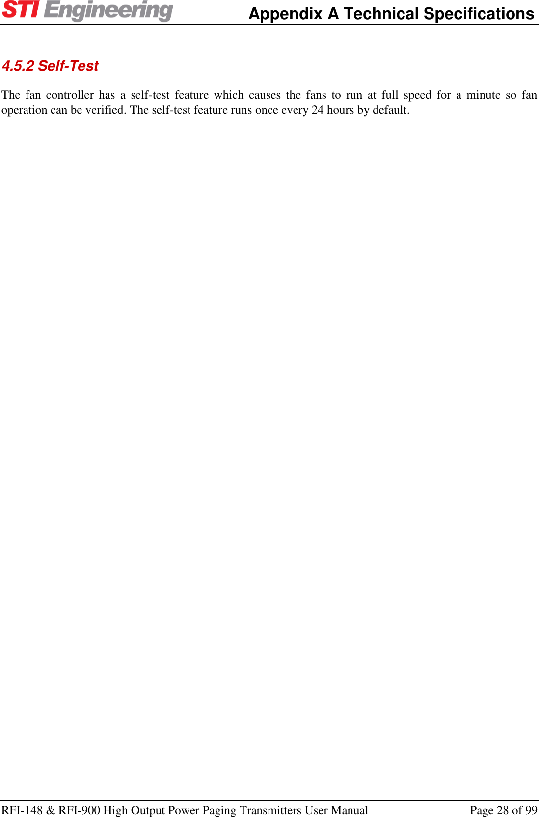
![Appendix A Technical Specifications RFI-148 & RFI-900 High Output Power Paging Transmitters User Manual Page 27 of 99 via Encoder Interface → 4-Level Operation. The “Legacy/Normal” operation was introduced in firmware 4.0, firmware versions prior to this operate implicitly in “Legacy” mode. H-Bit L-bit Deviation from Carrier (Hz) Legacy Normal N/C N/C +𝐹𝑑3 +𝐹𝑑3 N/C Gnd + 𝐹𝑑 −𝐹𝑑3 Gnd N/C −𝐹𝑑3 + 𝐹𝑑 Gnd Gnd −𝐹𝑑 −𝐹𝑑 Table 6: Custom 4-level deviation frequency offsets Where 𝐹𝑑 is the deviation frequency in Hz. 4.4.2 Carrier Offset The carrier offset setting is provided for use in simulcast paging networks. The offset from the carrier frequency can be specified for each protocol. The carrier offset can be set from +5000 to -5000 Hz in increments of 1 Hz. 4.4.3 Custom Deviation The transmitter supports generation of non-standard paging protocol settings. When the paging protocol custom is selected, the custom deviation and FSK level are used for that protocol. The custom deviation setting is useful for legacy paging systems with non-standard protocols and/or paging receivers. 4.5 Fan Control The transmitter has two fans for cooling; the front fan is an intake and the rear fan is the exhaust. The fans turn on at the configured fan turn on temperature, and then turn off at the configured fan turn off temperature. The temperature reference is configurable to either individual sensors, the hottest of all sensors, or the hottest of all sensors on the PA and Isolator (‘PA Group Sensors’). 4.5.1 Fan Override There is a fan override feature available to force the fans to turn on at full speed. When fan override is set to always on the fans will turn on and ignore the reference temperature. Paging Protocols -> Profile [1|2] -> Carrier Offset Paging Protocols -> Advanced Fan Control](https://usermanual.wiki/STI-Engineering/RFI900/User-Guide-3954511-Page-28.png)


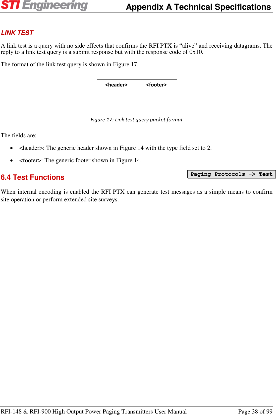
![Appendix A Technical Specifications RFI-148 & RFI-900 High Output Power Paging Transmitters User Manual Page 35 of 99 6.3 Protocols Supported All protocols are accessible through either the rear serial port or the Ethernet port via TCP or UDP port 64250. 6.3.1 TNPP The RFI PTX supports the ETE REQ and CAP PAGE block types. The TNPP station address is configurable. 6.3.2 PET The RFI PTX supports the PG1 and PG3 page submission types. Note that the page “zone” for PG3 has no effect on the RFI PTX and it only accepts this value for backwards compatibility. Also accepted is a password up to length 6 characters. The password is not checked and also exists only for backwards compatibility. There are several options available to allow for differences in PET implementations: Line Separator: The RFI PTX can print either a carriage return (<CR>) or a carriage return and line feed (<CR><LF>) for line separation. Note that the RFI PTX only accepts lines separated by <CR>. Timeout: The timeout while expecting the next command string is configurable. The RFI PTX starts a timer when it is expecting more data. If the timeout expires the RFI PTX PET parsing returns to either the Idle or Logged In state. Baud Rate: Due to PET not having a way to submit baud rate with page messages, the baud rate must be pre-configured. Standard POCSAG baud rates of 512, 1200, and 2400 are supported. Stay Logged In: This option allows the RFI PTX to remain in the Logged In state (ie, after the PG1 and password sequence) so messages can be submitted without having to handshake the connection each time. This option can be used in conjunction with Implied Login to skip handshaking altogether. Implied Login: If the <STX> character (the start of a message submission) is sent to the RFI PTX this option allows the RFI PTX to transition directly to message submission state and skip the login handshaking. Detect Numeric Pages: Encode a paging message as numeric if all characters within the message fit the numeric encoding scheme (ie, all characters are any of the following: '0', '1', '2', '3', '4', '5', '6', '7', '8', '9', '!', 'U', ' ', '-', ']', '['). 6.3.3 TAP The TAP protocol is treated the same as PET, however with some extensions: Paging Protocols -> Encoding Mode Paging Protocols -> TNPP Paging Protocols -> TAP/PET Paging Protocols -> TAP/PET](https://usermanual.wiki/STI-Engineering/RFI900/User-Guide-3954511-Page-36.png)


![Appendix C Management Reference RFI-148 & RFI-900 High Output Power Paging Transmitters User Manual Page 50 of 99 Appendix C Management Reference C.1 Serial Port Diagnostics Name Description AT Rx Total The size of the input buffer. I20[p,0] Rx Used The number of bytes currently stored in the input buffer. I20[p,1] Rx Bytes The total number of bytes received. I20[p,2] Rx Errors The total number of receive errors that have occurred. Sum of Rx Overflows, Rx Overruns, Rx Framing, and Rx Parity errors. I20[p,3] Rx Overflows The number of receive overflow errors that have occurred. An overflow occurs when data is received, but the buffer is full. I20[p,4] Rx Overruns The number of overrun errors that have occurred. An overrun occurs when the device is overloaded and cannot handle the incoming data. I20[p,5] Rx Framing The number of framing errors that have occurred. Framing errors usually occur due to mismatched serial port baud rates. I20[p,6] Rx Parity The number of serial parity errors that have been detected. I20[p,7] Tx Total The size of the output buffer. I20[p,8] Tx Used The number of bytes currently stored in the output buffer. I20[p,9] Tx Bytes The total number of bytes that have been transmitted. I20[p,10] Tx Errors The total number of errors that have occurred while transmitting. This is equal to the Tx Overflows count. I20[p,11] Tx Overflows The number of transmit overflow errors that have occurred. This occurs when there is data to transmit, but the buffer is full. I20[p,12] Table 21: Serial Port Statistics](https://usermanual.wiki/STI-Engineering/RFI900/User-Guide-3954511-Page-51.png)


![Appendix D Hayes AT Reference RFI-148 & RFI-900 High Output Power Paging Transmitters User Manual Page 56 of 99 PTT Override Status If PTT is currently disabled, describes what is the source of the override. ATP6: Returns the current value of PTT Override Status. PTT Override Master override allowing transmission to be completely disabled, regardless of PTT inputs. ATP7: Returns the current value of PTT Override. ATP7=n sets PTT Override to n Values accepted: 0 = Enable Transmit 1 = Disable Transmit PTT Turn Off Delay Delay before turning off the transmitter after PTT off is signalled. ATP112: Returns the current value of PTT Turn Off Delay. ATP112=n[.m]: Sets the value of PTT Turn Off Delay to n s, given that 0.000 <= n <= 65.535. Enable Transmit Timeout Enable or disable the transmit timeout feature. ATP117: Returns the current value of Enable Transmit Timeout. ATP117=n sets Enable Transmit Timeout to n Values accepted: 0 = False 1 = True Transmit Timeout Continuous transmission time, in seconds, which will cause a Transmit Timeout fault to occur. By default this will disable further transmission until the fault is cleared. ATP118: Returns the current value of Transmit Timeout. ATP118=n[.m]: Sets the value of Transmit Timeout to n s, given that 0.000 <= n <= 4294967.295. Absolute Delay Adjustment Applies an artificial transmission delay to all data. Can be used for matching delay in heterogeneous transmitter networks. ATI154: Returns the current value of Absolute Delay Adjustment. ATI154=n[.m]: Sets the value of Absolute Delay Adjustment to n ms, given that 0.000 <= n <= 40.000. Power Menu Transmitter Status Current transmission status. May be off, on, or waiting for PTT delay to expire before turning off. ATP115: Returns the current value of Transmitter Status. (Distributer) Max Tx Power Override the maximum configurable transmit power to a sublevel of the radios capabilities. ATS209: Returns the current value of Max Tx Power. ATS209=n: Sets the value of Max Tx Power to n W, given that 20 <= n <= 250. Tx Power](https://usermanual.wiki/STI-Engineering/RFI900/User-Guide-3954511-Page-57.png)
![Appendix D Hayes AT Reference RFI-148 & RFI-900 High Output Power Paging Transmitters User Manual Page 57 of 99 Transmitter output power setting. ATS45: Returns the current value of Tx Power. ATS45=n: Sets the value of Tx Power to n W, given that 20 <= n <= 250. Power Foldback The percent of transmit power in Watts to foldback to when the scale transmit power fault action goes active. ATP120: Returns the current value of Power Foldback. ATP120=n: Sets the value of Power Foldback to n %%, given that 0 <= n <= 100. Transmit On Software PTT method to key up the transmitter. ATP3: Runs the Transmit On routine. Transmit Off Software PTT method to key down the transmitter. ATP2: Runs the Transmit Off routine. Channel Menu Tx Range ATS183: Returns the current value of Tx Range. Current Tx Freq ATS184: Returns the current value of Current Tx Freq. Raster Read-only node for viewing the raster frequency of the radio. ATS185: Returns the current value of Raster. Channel Width Read-only node for viewing the channel width of the radio. ATS186: Returns the current value of Channel Width. Current Channel Currently selected radio channel number. ATS54: Returns the current value of Current Channel. ATS54=n: Sets the value of Current Channel to n , given that 1 <= n <= 17. (Distributer) Channel Count Number of channels that can be switched between using the current channel setting. ATS210: Returns the current value of Channel Count. ATS210=n: Sets the value of Channel Count to n , given that 1 <= n <= 16. Advanced Menu (Distributer) Tx Base Freq Minimum transmit frequency. ATS211: Returns the current value of Tx Base Freq. ATS211=n[.m]: Sets the value of Tx Base Freq to n MHz, given that 130.000000 <= n <= 1050.000000. (Distributer) Bandwidth](https://usermanual.wiki/STI-Engineering/RFI900/User-Guide-3954511-Page-58.png)
![Appendix D Hayes AT Reference RFI-148 & RFI-900 High Output Power Paging Transmitters User Manual Page 58 of 99 The amount of usable frequncies available to the radio. ATS212: Returns the current value of Bandwidth. ATS212=n[.m]: Sets the value of Bandwidth to n MHz, given that 1.000000 <= n <= 100.000000. (Distributer) Raster Frequency raster. All channel frequencies must be divisible by the raster. ATS57: Returns the current value of Raster. ATS57=n sets Raster to n Values accepted: 0 = 0.001 kHz 1 = 2.500 kHz 2 = 5.000 kHz 3 = 6.250 kHz 4 = 7.500 kHz 5 = 10.000 kHz 6 = 12.500 kHz 7 = 15.000 kHz 8 = 20.000 kHz 9 = 25.000 kHz 10 = 30.000 kHz Channel Width The radios channel width. ATS66: Returns the current value of Channel Width. ATS66=n sets Channel Width to n Values accepted: 0 = 12.500 KHz 1 = 25.000 KHz Channel Table Tx Freq Radio channel transmit frequency. ATS55[a]: Returns the current value of Tx Freq. ATS55[a]=n[.m]: Sets the value of Tx Freq to n MHz, given that 130.000000 <= n <= 1050.000000. Where: a = Channel Table table index (starting from 1) Reference Menu Current Reference The current reference being used to generate channel frequencies. ATI122: Returns the current value of Current Reference. External Reference The state of the external reference. ATI123: Returns the current value of External Reference. Reference Mode The reference selection method. ATI120: Returns the current value of Reference Mode. ATI120=n sets Reference Mode to n Values accepted:](https://usermanual.wiki/STI-Engineering/RFI900/User-Guide-3954511-Page-59.png)
![Appendix D Hayes AT Reference RFI-148 & RFI-900 High Output Power Paging Transmitters User Manual Page 59 of 99 0 = Internal 1 = External With Failover Ext. Ref. Frequency Configures the frequency of the external reference. ATI121: Returns the current value of Ext. Ref. Frequency. ATI121=n sets Ext. Ref. Frequency to n Values accepted: 0 = 5 MHz 1 = 10 MHz Isolator Menu Feedback Hardware feedback from the isolator attentuation switchout mechanism. ATP33: Returns the current value of Feedback. Isolator Mode Sets the isolator for normal transmission (high attenuation on RF diag port) or for listening to signal from antenna, for network testing (low attenuation on RF diag port, transmission disabled). ATP31: Returns the current value of Isolator Mode. ATP31=n sets Isolator Mode to n Values accepted: 0 = Set for Transmitting 1 = Set for Listening Listening Mode Timeout A timeout in seconds that starts when the isolator is set to listening mode. When the timeout expires the isolator will automatically return to transmitting mode. ATP35: Returns the current value of Listening Mode Timeout. ATP35=n[.m]: Sets the value of Listening Mode Timeout to n s, given that 0.000 <= n <= 65.535. Enable Listening Timeout Enables or disables listening mode timeout. ATP34: Returns the current value of Enable Listening Timeout. ATP34=n sets Enable Listening Timeout to n Values accepted: 0 = Disabled 1 = Enabled Paging Protocols Menu POCSAG Deviation ATP105: Returns the current value of POCSAG Deviation. FLEX Deviation ATP106: Returns the current value of FLEX Deviation. Encoding Mode Configure the encoding source for paging transmitter data. ATN10: Returns the current value of Encoding Mode. ATN10=n sets Encoding Mode to n Values accepted:](https://usermanual.wiki/STI-Engineering/RFI900/User-Guide-3954511-Page-60.png)
![Appendix D Hayes AT Reference RFI-148 & RFI-900 High Output Power Paging Transmitters User Manual Page 60 of 99 0 = External Encoder 1 = TNPP Serial 2 = TNPP TCP:64250 3 = TNPP UDP:64250 4 = PET/TAP Serial 5 = PET/TAP TCP:64250 6 = PET/TAP UDP:64250 PET/TAP Menu Current State ATN43: Returns the current value of Current State. Line Separator The line separator output between new lines. Configurable for compatibility across terminals. ATN15: Returns the current value of Line Separator. ATN15=n sets Line Separator to n Values accepted: 0 = 1 = Timeout Intercharacter timeout before purging input buffer and reverting to idle state. ATN16: Returns the current value of Timeout. ATN16=n[.m]: Sets the value of Timeout to n s, given that 0.5 <= n <= 10.0. Baud Rate Baud rate at which encoded POSCAG pages are sent over the air. ATN19: Returns the current value of Baud Rate. ATN19=n sets Baud Rate to n Values accepted: 0 = 512 1 = 1200 2 = 2400 Stay Logged In Remains logged in indefinitely after receiving a valid login string. ATN41: Returns the current value of Stay Logged In. ATN41=n sets Stay Logged In to n Values accepted: 0 = False 1 = True Implied Login Option to skip login sequence if a <STX> is read while waiting for wake up sequence. ATN42: Returns the current value of Implied Login. ATN42=n sets Implied Login to n Values accepted: 0 = Disabled 1 = PG1 2 = PG3](https://usermanual.wiki/STI-Engineering/RFI900/User-Guide-3954511-Page-61.png)
![Appendix D Hayes AT Reference RFI-148 & RFI-900 High Output Power Paging Transmitters User Manual Page 61 of 99 Detect Numeric Pages When enabled, will encode a POCSAG page in numeric format (rather than alpha-numeric) if the message is wholly formed by digits. ATN14: Returns the current value of Detect Numeric Pages. ATN14=n sets Detect Numeric Pages to n Values accepted: 0 = False 1 = True Group Code Allows the use of the final character or digit in the Pager ID field of a message submission to determine the function bits of the paging message. ATN13: Returns the current value of Group Code. ATN13=n sets Group Code to n Values accepted: 0 = None 1 = Trailing Character 2 = Trailing Digit Reset Statistics Reset the TAP/PET statistics accumulated since start-up. ATN17: Runs the Reset Statistics routine. Statistics Table Name Value ATN18[a]: Returns the current value of Value. Where: a = Statistics table index (starting from 0) TNPP Menu Address The address of this TNPP node. ATN23: Returns the current value of Address. ATN23=n: Sets the value of Address to n , given that 0 <= n <= 65535. Promiscuous Mode When enabled, this node will accept packets destined for any address. ATN24: Returns the current value of Promiscuous Mode. ATN24=n sets Promiscuous Mode to n Values accepted: 0 = False 1 = True Transparent CRC support ATN25: Returns the current value of Transparent CRC support. ATN25=n sets Transparent CRC support to n Values accepted: 0 = False 1 = True](https://usermanual.wiki/STI-Engineering/RFI900/User-Guide-3954511-Page-62.png)
![Appendix D Hayes AT Reference RFI-148 & RFI-900 High Output Power Paging Transmitters User Manual Page 62 of 99 Address Extension support ATN26: Returns the current value of Address Extension support. ATN26=n sets Address Extension support to n Values accepted: 0 = False 1 = True Multi-Block support ATN27: Returns the current value of Multi-Block support. ATN27=n sets Multi-Block support to n Values accepted: 0 = False 1 = True Large Packet support ATN28: Returns the current value of Large Packet support. ATN28=n sets Large Packet support to n Values accepted: 0 = False 1 = True Reset TNPP Statistics ATN22: Runs the Reset TNPP Statistics routine. TNPP Statistics Table Name ATN20[a]: Returns the current value of Name . Where: a = TNPP Statistics table index (starting from 0) Count ATN21[a]: Returns the current value of Count. Where: a = TNPP Statistics table index (starting from 0) POCSAG Menu Preamble Length Length of the preamble sent prior to paging data. ATN30: Returns the current value of Preamble Length. ATN30=n: Sets the value of Preamble Length to n bit, given that 32 <= n <= 2304. Function Override Override the function bits in the address codeword. Default (`Message Encoding`) is to set the function bits based on message encoding: Numeric: 00, Tone: 01, Alpha-numeric: 11. ATN11: Returns the current value of Function Override. ATN11=n sets Function Override to n Values accepted: 0 = Message Encoding 1 = Always 00 2 = Always 01 3 = Always 10 4 = Always 11](https://usermanual.wiki/STI-Engineering/RFI900/User-Guide-3954511-Page-63.png)
![Appendix D Hayes AT Reference RFI-148 & RFI-900 High Output Power Paging Transmitters User Manual Page 63 of 99 Purge Timeout Duration to wait to collate paging messages for sending over the air. ATN29: Returns the current value of Purge Timeout. ATN29=n: Sets the value of Purge Timeout to n ms, given that 250 <= n <= 5000. Reset Statistics ATN40: Runs the Reset Statistics routine. Page Repeat Rules Table Enabled Whether this rule is enabled. ATN36[a]: Returns the current value of Enabled. ATN36[a]=n sets Enabled to n Values accepted: 0 = False 1 = True Where: a = Page Repeat Rules table index (starting from 0) Capcode The Capcode to match for this rule. 0 matches any capcode, all other integers match the specific capcode. ATN37[a]: Returns the current value of Capcode. ATN37[a]=n: Sets the value of Capcode to n , given that 0 <= n <= 2097152. Where: a = Page Repeat Rules table index (starting from 0) Delay The delay to insert between page repetitions. ATN38[a]: Returns the current value of Delay. ATN38[a]=n: Sets the value of Delay to n s, given that 4 <= n <= 60. Where: a = Page Repeat Rules table index (starting from 0) Count The number of times to repeat pages. ATN39[a]: Returns the current value of Count. ATN39[a]=n: Sets the value of Count to n , given that 1 <= n <= 5. Where: a = Page Repeat Rules table index (starting from 0) POCSAG MAC Statistics Table Name ATN34[a]: Returns the current value of Name. Where: a = POCSAG MAC Statistics table index (starting from 0) Count ATN35[a]: Returns the current value of Count. Where: a = POCSAG MAC Statistics table index (starting from 0) Test Menu Status ATG171: Returns the current value of Status. Message](https://usermanual.wiki/STI-Engineering/RFI900/User-Guide-3954511-Page-64.png)

![Appendix D Hayes AT Reference RFI-148 & RFI-900 High Output Power Paging Transmitters User Manual Page 65 of 99 The deviation of the custom paging protocol. ATP103: Returns the current value of Custom Deviation. ATP103=n[.m]: Sets the value of Custom Deviation to n Hz, given that 0.0 <= n <= 4800.0. Custom FSK level The FSK-levels of the custom paging protocol. ATP104: Returns the current value of Custom FSK level. ATP104=n sets Custom FSK level to n Values accepted: 0 = 2-level 1 = 4-level Profiles Table Paging Protocol Configured paging protocol for this profile. ATP91[a]: Returns the current value of Paging Protocol. ATP91[a]=n sets Paging Protocol to n Values accepted: 0 = POCSAG 1 = FLEX-2 2 = FLEX-4 3 = Custom Where: a = Profiles table index (starting from 0) Carrier Offset Configured carrier frequency offset for this profile. ATP92[a]: Returns the current value of Carrier Offset. ATP92[a]=[+/-]n: Sets the value of Carrier Offset to n Hz, given that -4000 <= n <= 4000. Where: a = Profiles table index (starting from 0) Ext. Data Clock Configures whether to use an external clock to synchronise data. An external clock is mandatory for 4-level protocols. ATP93[a]: Returns the current value of Ext. Data Clock. ATP93[a]=n sets Ext. Data Clock to n Values accepted: 0 = Disabled 1 = Enabled Where: a = Profiles table index (starting from 0) Fan Control Menu Sensed Temp. Current temperature at sensor used for fan control. ATP109: Returns the current value of Sensed Temp.. Time Until Fan Test ATP111: Returns the current value of Time Until Fan Test. Fan Override Manual fan override (allows fans to be forced on). ATP22: Returns the current value of Fan Override.](https://usermanual.wiki/STI-Engineering/RFI900/User-Guide-3954511-Page-66.png)
![Appendix D Hayes AT Reference RFI-148 & RFI-900 High Output Power Paging Transmitters User Manual Page 66 of 99 ATP22=n sets Fan Override to n Values accepted: 0 = Normal 1 = Always On Sensor To Use Temperature sensor used for fan control. ATP108: Returns the current value of Sensor To Use. ATP108=n sets Sensor To Use to n Values accepted: 0 = Baseband Sensor 1 = PA Sensor 2 = Driver Sensor 3 = PA/Driver Ambient Sensor 4 = Isolator Sensor 5 = Baseband Thermistor 6 = PA Group Average 7 = Hottest Sensor 8 = PA Group Sensors Turn On Temp. Sensed temperature above which fans will be turned on. ATP20: Returns the current value of Turn On Temp.. ATP20=[+/-]n: Sets the value of Turn On Temp. to n deg C, given that -128 <= n <= 127. Turn Off Temp. Sensed temperature below which fans will be turned off. ATP21: Returns the current value of Turn Off Temp.. ATP21=[+/-]n: Sets the value of Turn Off Temp. to n deg C, given that -128 <= n <= 127. Fan Test Interval Interval in hours between fan self-tests. ATP110: Returns the current value of Fan Test Interval. ATP110=n: Sets the value of Fan Test Interval to n hrs, given that 12 <= n <= 48. Sensors Menu (Distributer) Fault Reporting ATI203: Returns the current value of Fault Reporting. ATI203=n sets Fault Reporting to n Values accepted: 0 = Disabled 1 = Enabled (Distributer) Fail-safes ATI204: Returns the current value of Fail-safes. ATI204=n sets Fail-safes to n Values accepted: 0 = Disabled 1 = Enabled Sensor Configuration Menu](https://usermanual.wiki/STI-Engineering/RFI900/User-Guide-3954511-Page-67.png)
![Appendix D Hayes AT Reference RFI-148 & RFI-900 High Output Power Paging Transmitters User Manual Page 67 of 99 Reset Cutoffs ATI207: Runs the Reset Cutoffs routine. Reset Min/Max Reset the historical minimums and maximums of monitored sensor values. ATI104: Runs the Reset Min/Max routine. Status Parameters Table Name Name of the sensor and its unit in this row of the table. ATI176[a]: Returns the current value of Name. Where: a = Status Parameters table index (starting from 0) Current Current measured sensor value. ATI90[a]: Returns the current value of Current. Where: a = Status Parameters table index (starting from 0) Relevant Value The current measured sensor value if it is relevant. Otherwise -2000000 ATI99[a]: Returns the current value of Relevant Value. Where: a = Status Parameters table index (starting from 0) Maximum Maximum recorded sensor value since the statistics were reset. ATI91[a]: Returns the current value of Maximum. Where: a = Status Parameters table index (starting from 0) Minimum Minimum recorded sensor value since the statistics were reset. ATI92[a]: Returns the current value of Minimum. Where: a = Status Parameters table index (starting from 0) Current State Current fault status associated with this sensor. ATI177[a]: Returns the current value of Current State. Where: a = Status Parameters table index (starting from 0) Upper Cutoff Upper cutoff value for this sensor. Measurements which exceed this cutoff cause a fault. ATI93[a]: Returns the current value of Upper Cutoff. Where: a = Status Parameters table index (starting from 0) Hysteresis Hysteresis value for this sensor. When a sensor is near the cutoff value this helps reduce excessive fault toggling. ATI97[a]: Returns the current value of Hysteresis. ATI97[a]=n: Sets the value of Hysteresis to n , given that 0 <= n <= 65535. Where: a = Status Parameters table index (starting from 0) Lower Cutoff](https://usermanual.wiki/STI-Engineering/RFI900/User-Guide-3954511-Page-68.png)
![Appendix D Hayes AT Reference RFI-148 & RFI-900 High Output Power Paging Transmitters User Manual Page 68 of 99 Lower cutoff value for this sensor. Measurements lower than this cutoff cause a fault. ATI96[a]: Returns the current value of Lower Cutoff. Where: a = Status Parameters table index (starting from 0) Reset Sensor Min/Max Reset the historical minimum and maximum for this sensor. ATI181[a]: Runs the Reset Sensor Min/Max routine. Where: a = Status Parameters table index (starting from 0) Sensor Interpolation Menu Transmit Power Variation Table Name Name of the sensor and its unit in this row of the table. ATG156[a]: Returns the current value of Name. Where: a = Transmit Power Variation table index (starting from 0) 20W Lower Cutoff ATG157[a]: Returns the current value of 20W Lower Cutoff. ATG157[a]=[+/-]n: Sets the value of 20W Lower Cutoff to n , given that -2147483648 <= n <= 2147483647. Where: a = Transmit Power Variation table index (starting from 0) 20W Upper Cutoff ATG158[a]: Returns the current value of 20W Upper Cutoff. ATG158[a]=[+/-]n: Sets the value of 20W Upper Cutoff to n , given that -2147483648 <= n <= 2147483647. Where: a = Transmit Power Variation table index (starting from 0) 50W Lower Cutoff ATG159[a]: Returns the current value of 50W Lower Cutoff. ATG159[a]=[+/-]n: Sets the value of 50W Lower Cutoff to n , given that -2147483648 <= n <= 2147483647. Where: a = Transmit Power Variation table index (starting from 0) 50W Upper Cutoff ATG160[a]: Returns the current value of 50W Upper Cutoff. ATG160[a]=[+/-]n: Sets the value of 50W Upper Cutoff to n , given that -2147483648 <= n <= 2147483647. Where: a = Transmit Power Variation table index (starting from 0) 100W Lower Cutoff ATG161[a]: Returns the current value of 100W Lower Cutoff. ATG161[a]=[+/-]n: Sets the value of 100W Lower Cutoff to n , given that -2147483648 <= n <= 2147483647. Where: a = Transmit Power Variation table index (starting from 0) 100W Upper Cutoff ATG162[a]: Returns the current value of 100W Upper Cutoff. ATG162[a]=[+/-]n: Sets the value of 100W Upper Cutoff to n , given that -2147483648 <= n <= 2147483647. Where: a = Transmit Power Variation table index (starting from 0) 200W Lower Cutoff ATG163[a]: Returns the current value of 200W Lower Cutoff. ATG163[a]=[+/-]n: Sets the value of 200W Lower Cutoff to n , given that -2147483648 <= n <= 2147483647. Where: a = Transmit Power Variation table index (starting from 0)](https://usermanual.wiki/STI-Engineering/RFI900/User-Guide-3954511-Page-69.png)
![Appendix D Hayes AT Reference RFI-148 & RFI-900 High Output Power Paging Transmitters User Manual Page 69 of 99 200W Upper Cutoff ATG164[a]: Returns the current value of 200W Upper Cutoff. ATG164[a]=[+/-]n: Sets the value of 200W Upper Cutoff to n , given that -2147483648 <= n <= 2147483647. Where: a = Transmit Power Variation table index (starting from 0) 250W Lower Cutoff ATG165[a]: Returns the current value of 250W Lower Cutoff. ATG165[a]=[+/-]n: Sets the value of 250W Lower Cutoff to n , given that -2147483648 <= n <= 2147483647. Where: a = Transmit Power Variation table index (starting from 0) 250W Upper Cutoff ATG166[a]: Returns the current value of 250W Upper Cutoff. ATG166[a]=[+/-]n: Sets the value of 250W Upper Cutoff to n , given that -2147483648 <= n <= 2147483647. Where: a = Transmit Power Variation table index (starting from 0) Other Table Name Name of the sensor and its unit in this row of the table. ATG167[a]: Returns the current value of Name. Where: a = Other table index (starting from 0) Lower Cutoff ATG169[a]: Returns the current value of Lower Cutoff. ATG169[a]=[+/-]n: Sets the value of Lower Cutoff to n , given that -2147483648 <= n <= 2147483647. Where: a = Other table index (starting from 0) Upper Cutoff ATG168[a]: Returns the current value of Upper Cutoff. ATG168[a]=[+/-]n: Sets the value of Upper Cutoff to n , given that -2147483648 <= n <= 2147483647. Where: a = Other table index (starting from 0) Temperature Sensors Table Voltage Sensors Table Current Sensors Table Fan Speeds Table Power Table Ratio Table Faults Menu Total Faults Counter ATI156: Returns the current value of Total Faults Counter. Active Faults ATI157: Returns the current value of Active Faults. Combined Fault Status The status of the combined alarm. ATI158: Returns the current value of Combined Fault Status. Overview Filter](https://usermanual.wiki/STI-Engineering/RFI900/User-Guide-3954511-Page-70.png)
![Appendix D Hayes AT Reference RFI-148 & RFI-900 High Output Power Paging Transmitters User Manual Page 70 of 99 ATI155: Returns the current value of Overview Filter. ATI155=n sets Overview Filter to n Values accepted: 0 = Show All 1 = Show Active/Latched 2 = Show Counter > 0 Clear All Faults Clears all active faults and reverts all fault actions that have been taken. ATI151: Runs the Clear All Faults routine. Fault Configuration Menu Combined Fault Ext. Alarm The hardware alarm associated with the combined alarm. ATI173: Returns the current value of Combined Fault Ext. Alarm. ATI173=n sets Combined Fault Ext. Alarm to n Values accepted: 0 = ALM1 1 = ALM2 2 = ALM3 3 = ALM4 4 = ALM5 5 = ALM6 6 = ALM7 7 = ALM8 8 = ALM9 9 = COMB 10 = ALM10 11 = ALM11 12 = ALM12 13 = ALM13 14 = None Min. Fault Duration The minimum duration a parameter must be in its fault condition before it is reported. ATI172: Returns the current value of Min. Fault Duration. ATI172=n[.m]: Sets the value of Min. Fault Duration to n s, given that 0.000 <= n <= 65.535. Fault Beeper ATI174: Returns the current value of Fault Beeper. ATI174=n sets Fault Beeper to n Values accepted: 0 = Never 1 = Activity 2 = Heartbeat Reset Counters ATI163: Runs the Reset Counters routine. Faults Table Fault Name](https://usermanual.wiki/STI-Engineering/RFI900/User-Guide-3954511-Page-71.png)
![Appendix D Hayes AT Reference RFI-148 & RFI-900 High Output Power Paging Transmitters User Manual Page 71 of 99 Name of the fault in this row of the table. ATI164[a]: Returns the current value of Fault Name. Where: a = Faults table index (starting from 0) Status Indicates whether or not this fault condition is currently active. ATI165[a]: Returns the current value of Status. Where: a = Faults table index (starting from 0) Active Duration Duration for which this fault has been active, or 0 if the fault is not active. ATI170[a]: Returns the current value of Active Duration. Where: a = Faults table index (starting from 0) Ext. Alarm The hardware alarm that will be asserted when this fault is active. ATI166[a]: Returns the current value of Ext. Alarm. ATI166[a]=n sets Ext. Alarm to n Values accepted: 0 = ALM1 1 = ALM2 2 = ALM3 3 = ALM4 4 = ALM5 5 = ALM6 6 = ALM7 7 = ALM8 8 = ALM9 9 = COMB 10 = ALM10 11 = ALM11 12 = ALM12 13 = ALM13 14 = None Where: a = Faults table index (starting from 0) Fault Action Configured action to be taken when this fault occurs. ATI167[a]: Returns the current value of Fault Action. ATI167[a]=n sets Fault Action to n Values accepted: 0 = None 1 = Reference Switchover 2 = Disable Transmit 3 = Scale Transmit Power 4 = Enable PA0 Current Foldback 5 = Enable PA90 Current Foldback 6 = Enable Reverse Power Foldback Where: a = Faults table index (starting from 0) Latching Mechanism](https://usermanual.wiki/STI-Engineering/RFI900/User-Guide-3954511-Page-72.png)
![Appendix D Hayes AT Reference RFI-148 & RFI-900 High Output Power Paging Transmitters User Manual Page 72 of 99 Configured latching mechanism for this fault. ATI168[a]: Returns the current value of Latching Mechanism. ATI168[a]=n sets Latching Mechanism to n Values accepted: 0 = None 1 = SW Reset Where: a = Faults table index (starting from 0) Triggers Combined Allows this fault to assert the combined alarm (COMB) in addition to it's configured alarm. ATI169[a]: Returns the current value of Triggers Combined. ATI169[a]=n sets Triggers Combined to n Values accepted: 0 = False 1 = True Where: a = Faults table index (starting from 0) Go Standby Configures this fault as a TX FAULT for the purposes of entering standby mode when Hot Standby operation is enabled ATM17[a]: Returns the current value of Go Standby. ATM17[a]=n sets Go Standby to n Values accepted: 0 = False 1 = True Where: a = Faults table index (starting from 0) Counter The number of times this fault has occurred since the statistics were reset. ATI171[a]: Returns the current value of Counter. ATI171[a]=n: Sets the value of Counter to n , given that 0 <= n <= 65535. Where: a = Faults table index (starting from 0) Faults Overview Table Fault ATI159[a]: Returns the current value of Fault. Where: a = Faults Overview table index (starting from 0) Status ATI160[a]: Returns the current value of Status. Where: a = Faults Overview table index (starting from 0) Active Duration ATI161[a]: Returns the current value of Active Duration. Where: a = Faults Overview table index (starting from 0) Counter ATI162[a]: Returns the current value of Counter. Where: a = Faults Overview table index (starting from 0) Encoder Interface Menu](https://usermanual.wiki/STI-Engineering/RFI900/User-Guide-3954511-Page-73.png)
![Appendix D Hayes AT Reference RFI-148 & RFI-900 High Output Power Paging Transmitters User Manual Page 73 of 99 Encoder Detected ATP102: Returns the current value of Encoder Detected. Data Idle Duration ATP94: Returns the current value of Data Idle Duration. 24 V DC Current ATP126: Returns the current value of 24 V DC Current. Data Idle Timeout Configurable timeout for detecting the encoder data inputs as idle, which will cause the encoder data idle fault to go active. ATP95: Returns the current value of Data Idle Timeout. ATP95=n[.m]: Sets the value of Data Idle Timeout to n s, given that 0.000 <= n <= 4294967.295. Report Data Idle Enable or disable reporting of idle encoder data fault. ATP96: Returns the current value of Report Data Idle. ATP96=n sets Report Data Idle to n Values accepted: 0 = False 1 = True 4-Level Operation Allows swapping of L-/H-bit. ATP124: Returns the current value of 4-Level Operation. ATP124=n sets 4-Level Operation to n Values accepted: 0 = Normal 1 = Legacy Encoder Protocol Control Allows the active protocol profile to be toggled by hardware input. ATP99: Returns the current value of Encoder Protocol Control. ATP99=n sets Encoder Protocol Control to n Values accepted: 0 = Disabled 1 = Enabled Encoder Channel Control Allows the active channel to be toggled by hardware input. ATS180: Returns the current value of Encoder Channel Control. ATS180=n sets Encoder Channel Control to n Values accepted: 0 = Disabled 1 = Enabled Encoder Hardware PTT Allows transmitter PTT to be controlled by hardware input. ATP97: Returns the current value of Encoder Hardware PTT.](https://usermanual.wiki/STI-Engineering/RFI900/User-Guide-3954511-Page-74.png)
![Appendix D Hayes AT Reference RFI-148 & RFI-900 High Output Power Paging Transmitters User Manual Page 74 of 99 ATP97=n sets Encoder Hardware PTT to n Values accepted: 0 = Disabled 1 = Enabled Tx On Active Level Configures which state is considered to be active with hardware PTT. ATP98: Returns the current value of Tx On Active Level. ATP98=n sets Tx On Active Level to n Values accepted: 0 = Active Low 1 = Active High Auto PTT Setting to enable or disable the automatic Push-To-Talk on data feature. ATP100: Returns the current value of Auto PTT. ATP100=n sets Auto PTT to n Values accepted: 0 = Disabled 1 = Enabled Auto PTT Timeout No-data timeout for the automatic PTT feature. ATP101: Returns the current value of Auto PTT Timeout. ATP101=n[.m]: Sets the value of Auto PTT Timeout to n s, given that 0.000 <= n <= 65.535. Active Profile Active protocol profile. ATP90: Returns the current value of Active Profile. ATP90=n sets Active Profile to n Values accepted: 0 = Profile 1 1 = Profile 2 Aux Input 1 Debounce ATP121: Returns the current value of Aux Input 1 Debounce. ATP121=n[.m]: Sets the value of Aux Input 1 Debounce to n s, given that 0.5 <= n <= 120.0. Aux Input 1 Active Level ATP122: Returns the current value of Aux Input 1 Active Level. ATP122=n sets Aux Input 1 Active Level to n Values accepted: 0 = Low 1 = High Clock Edge Configures the clock edge to use when using an external data clock. ATI152: Returns the current value of Clock Edge. ATI152=n sets Clock Edge to n Values accepted:](https://usermanual.wiki/STI-Engineering/RFI900/User-Guide-3954511-Page-75.png)
![Appendix D Hayes AT Reference RFI-148 & RFI-900 High Output Power Paging Transmitters User Manual Page 75 of 99 0 = Rising-edge 1 = Falling-edge Data Invert Set to true to invert data internally before modulation. ATI153: Returns the current value of Data Invert. ATI153=n sets Data Invert to n Values accepted: 0 = Normal 1 = Inverted 24 V DC Output ATP125: Returns the current value of 24 V DC Output. ATP125=n sets 24 V DC Output to n Values accepted: 0 = Disabled 1 = Enabled 24 V DC Cycle ATP127: Runs the 24 V DC Cycle routine. External I/O Table Name ATR248[a]: Returns the current value of Name. Where: a = External I/O table index (starting from 0) Direction ATR249[a]: Returns the current value of Direction. Where: a = External I/O table index (starting from 0) State ATR250[a]: Returns the current value of State. Where: a = External I/O table index (starting from 0) Hot Standby Menu Role ATM13: Returns the current value of Role. State ATM14: Returns the current value of State. RF Switch ATM15: Returns the current value of RF Switch. Can Go Active (HW) ATM11: Returns the current value of Can Go Active (HW). TX Fault ATM16: Returns the current value of TX Fault. Standby Mode](https://usermanual.wiki/STI-Engineering/RFI900/User-Guide-3954511-Page-76.png)

![Appendix D Hayes AT Reference RFI-148 & RFI-900 High Output Power Paging Transmitters User Manual Page 77 of 99 3 = Mirrors CTS 4 = Follows TX Settings Table Baud Rate The baud rate configured for this serial port. ATS100[a]: Returns the current value of Baud Rate. ATS100[a]=n sets Baud Rate to n Values accepted: 1 = 300 2 = 600 3 = 1200 4 = 2400 5 = 4800 6 = 9600 8 = 19200 9 = 38400 10 = 57600 11 = 115200 Where: a = Settings table index (starting from 0) Data Bits The number of data bits configured for this serial port. ATS102[a]: Returns the current value of Data Bits. ATS102[a]=n sets Data Bits to n Values accepted: 0 = 7 1 = 8 Where: a = Settings table index (starting from 0) Parity The parity configuration for this serial port. ATS101[a]: Returns the current value of Parity. ATS101[a]=n sets Parity to n Values accepted: 0 = None 1 = Even 2 = Odd Where: a = Settings table index (starting from 0) Stop Bits The number of stop bits used on this serial port. ATS103[a]: Returns the current value of Stop Bits. ATS103[a]=n sets Stop Bits to n Values accepted: 0 = 1 1 = 2 Where: a = Settings table index (starting from 0) Reset Statistics](https://usermanual.wiki/STI-Engineering/RFI900/User-Guide-3954511-Page-78.png)
![Appendix D Hayes AT Reference RFI-148 & RFI-900 High Output Power Paging Transmitters User Manual Page 78 of 99 ATS189[a]: Runs the Reset Statistics routine. Where: a = Settings table index (starting from 0) Statistics Table Name ATS188[a,b]: Returns the current value of Name. Where: a = Settings table index (starting from 0) b = Statistics table index (starting from 0) Value Shows statistics for serial port events. ATI20[a,b]: Returns the current value of Value. Where: a = Settings table index (starting from 0) b = Statistics table index (starting from 0) LAN Interface Menu Ethernet Menu Local MAC Address The factory-assigned Ethernet MAC address of the unit. ATR46: Returns the current value of Local MAC Address. Link Status ATR255: Returns the current value of Link Status. Auto Negotiation Status ATR256: Returns the current value of Auto Negotiation Status. Link Speed ATR257: Returns the current value of Link Speed. Link Duplex ATR258: Returns the current value of Link Duplex. Auto Negotiation Configure whether the Ethernet interface will automatically detect link speed and duplex. ATR259: Returns the current value of Auto Negotiation. ATR259=n sets Auto Negotiation to n Values accepted: 0 = Force 1 = Auto-negotiate Forced Link Speed Configures the speed to use when the link parameters are forced. ATR260: Returns the current value of Forced Link Speed. ATR260=n sets Forced Link Speed to n Values accepted: 0 = 10 Mbps 1 = 100 Mbps Forced Link Duplex Configures duplex when the link parameters are forced. ATR261: Returns the current value of Forced Link Duplex.](https://usermanual.wiki/STI-Engineering/RFI900/User-Guide-3954511-Page-79.png)
![Appendix D Hayes AT Reference RFI-148 & RFI-900 High Output Power Paging Transmitters User Manual Page 79 of 99 ATR261=n sets Forced Link Duplex to n Values accepted: 0 = Half duplex 1 = Full duplex TCP/IP Menu IP Address A read-only string that shows the current IP address of the unit. If DHCP is enabled this will be the IP address assigned by the DHCP server. If DHCP is disabled this will be the configured static IP address. ATI70: Returns the current value of IP Address. Subnet Mask ATI201: Returns the current value of Subnet Mask. Gateway ATI202: Returns the current value of Gateway. Bcast Addr ATI205: Returns the current value of Bcast Addr. TCP Idle Timeout Idle time before a TCP connection times out. ATG48: Returns the current value of TCP Idle Timeout. ATG48=n: Sets the value of TCP Idle Timeout to n s, given that 0 <= n <= 65535. UDP Idle Timeout Idle time before a UDP connection times out. ATG96: Returns the current value of UDP Idle Timeout. ATG96=n: Sets the value of UDP Idle Timeout to n s, given that 20 <= n <= 600. DHCP Client Enables or disables the DHCP client of this unit. When disabled, the unit will use the configured static IP address. ATI71: Returns the current value of DHCP Client. ATI71=n sets DHCP Client to n Values accepted: 0 = Disabled 1 = Enabled Hostname The hostname of the unit. ATI72: Returns the current value of Hostname. ATI72=s: Sets the value of Hostname to s, given that 0 <= length(s) <= 26. Static IP Configuration Table 1st Octet Get or set the 1st Octet of either IP address, subnet mask or gateway. ATI80[a]: Returns the current value of 1st Octet. ATI80[a]=n: Sets the value of 1st Octet to n , given that 0 <= n <= 255. Where: a = Static IP Configuration table index (starting from 0)](https://usermanual.wiki/STI-Engineering/RFI900/User-Guide-3954511-Page-80.png)
![Appendix D Hayes AT Reference RFI-148 & RFI-900 High Output Power Paging Transmitters User Manual Page 80 of 99 2nd Octet Get or set the 2nd Octet of either IP address, subnet mask or gateway. ATI81[a]: Returns the current value of 2nd Octet. ATI81[a]=n: Sets the value of 2nd Octet to n , given that 0 <= n <= 255. Where: a = Static IP Configuration table index (starting from 0) 3rd Octet Get or set the 3rd Octet of either IP address, subnet mask or gateway. ATI82[a]: Returns the current value of 3rd Octet. ATI82[a]=n: Sets the value of 3rd Octet to n , given that 0 <= n <= 255. Where: a = Static IP Configuration table index (starting from 0) 4th Octet Get or set the 4th Octet of either IP address, subnet mask or gateway. ATI83[a]: Returns the current value of 4th Octet. ATI83[a]=n: Sets the value of 4th Octet to n , given that 0 <= n <= 255. Where: a = Static IP Configuration table index (starting from 0) SNTP Menu Status ATG8: Returns the current value of Status. Last Sync ATG2: Returns the current value of Last Sync. Last Query Latency ATG5: Returns the current value of Last Query Latency. Mode ATG1: Returns the current value of Mode. ATG1=n sets Mode to n Values accepted: 0 = Disabled 1 = Unicast Server IP ATG3: Returns the current value of Server IP. ATG3=s: Sets the value of Server IP to s, given that 0 <= length(s) <= 32. Query Interval ATG4: Returns the current value of Query Interval. ATG4=n: Sets the value of Query Interval to n mins, given that 1 <= n <= 2880. Request Timeout ATG6: Returns the current value of Request Timeout. ATG6=n[.m]: Sets the value of Request Timeout to n s, given that 0.000 <= n <= 65.535. Send Request ATG7: Runs the Send Request routine. UDP Connections Table](https://usermanual.wiki/STI-Engineering/RFI900/User-Guide-3954511-Page-81.png)
![Appendix D Hayes AT Reference RFI-148 & RFI-900 High Output Power Paging Transmitters User Manual Page 81 of 99 Local Port ATG49[a]: Returns the current value of Local Port. Where: a = UDP Connections table index (starting from 0) Remote IP ATG50[a]: Returns the current value of Remote IP. Where: a = UDP Connections table index (starting from 0) Remote Port ATG51[a]: Returns the current value of Remote Port. Where: a = UDP Connections table index (starting from 0) Diagnostics Menu (Distributer) Estimated Life Uptime An approximation of the total number of hours that this device has been powered up. ATI206: Returns the current value of Estimated Life Uptime. Total Tx Time ATG155: Returns the current value of Total Tx Time. Startup Reason ATG9: Returns the current value of Startup Reason. Startup Config ATG154: Returns the current value of Startup Config. Approval Code International type approval code which applies to this device. ATI175: Returns the current value of Approval Code. EEPROM Status Displays the EEPROM status at start-up. Blank or Invalid EEPROM could indicate a hardware fault. ATR10: Returns the current value of EEPROM Status. Build Date The date the firmware was compiled. ATR9: Returns the current value of Build Date. Firmware Version Version information for the firmware loaded in this device. ATI4: Returns the current value of Firmware Version. FPGA Version Version information for the FPGA image loaded into this device. ATI18: Returns the current value of FPGA Version. Bootloader Version ATI130: Returns the current value of Bootloader Version. (Distributer) Assertion Messages](https://usermanual.wiki/STI-Engineering/RFI900/User-Guide-3954511-Page-82.png)

![Appendix D Hayes AT Reference RFI-148 & RFI-900 High Output Power Paging Transmitters User Manual Page 83 of 99 The hours portion of the time zone. ATG18[a]: Returns the current value of Hours. ATG18[a]=[+/-]n: Sets the value of Hours to n hrs, given that -12 <= n <= 14. Where: a = Time Zone (UTC +/-) table index (starting from 0) Minutes The minutes portion of the time zone. ATG19[a]: Returns the current value of Minutes. ATG19[a]=n: Sets the value of Minutes to n mins, given that 0 <= n <= 59. Where: a = Time Zone (UTC +/-) table index (starting from 0) Firmware Update Menu Current State ATU50: Returns the current value of Current State. Startup State ATU46: Returns the current value of Startup State. Snapshot Progress Displays the completion status of a firmware snapshot being created. ATU11: Returns the current value of Snapshot Progress. Use Schedule Information Use the schedule information in the CCMP-FIRMWARE-SCHEDULE packet to determine when to update to the new firmware image. ATU47: Returns the current value of Use Schedule Information. ATU47=n sets Use Schedule Information to n Values accepted: 0 = False 1 = True Update Firmware Now Update the firmware to the most recent uploaded firmware image. This operation cannot be reversed and can cause configuration loss. ATU17: Runs the Update Firmware Now routine. Take Firmware Snapshot Trigger a firmware snapshot to be created. The progress of the snapshot creation can be tracked under the node 'Snapshot Progress'. ATU10: Runs the Take Firmware Snapshot routine. Roll Back to Snapshot 'Roll Back' to the most recent firmware snapshot. This will load the firmware and configuration saved on the most recent firmware snapshot. This operation cannot be reversed. ATU15: Runs the Roll Back to Snapshot routine. Firmware Update Table ATU48[a]: Returns the current value of . Where: a = table index (starting from 0) Available](https://usermanual.wiki/STI-Engineering/RFI900/User-Guide-3954511-Page-84.png)
![Appendix D Hayes AT Reference RFI-148 & RFI-900 High Output Power Paging Transmitters User Manual Page 84 of 99 Displays availability of the firmware image saved into this memory bank. True means an image is available, false means there is no image. ATU20[a]: Returns the current value of Available. Where: a = table index (starting from 0) Type ATU49[a]: Returns the current value of Type. Where: a = table index (starting from 0) Version The firmware version of the firmware image loaded into this memory bank. ATU21[a]: Returns the current value of Version. Where: a = table index (starting from 0) Timestamp The creation date or upload date of the firmware image loaded into this memory bank. ATU22[a]: Returns the current value of Timestamp. Where: a = table index (starting from 0) (Distributer) Load Image ATU51[a]: Runs the Load Image routine. Where: a = table index (starting from 0) Ethernet Statistics Menu Ethernet Summary Statistics Table Name ATR251[a]: Returns the current value of Name. Where: a = Ethernet Summary Statistics table index (starting from 0) Value ATR252[a]: Returns the current value of Value. Where: a = Ethernet Summary Statistics table index (starting from 0) Ethernet Error Statistics Table Name ATR253[a]: Returns the current value of Name. Where: a = Ethernet Error Statistics table index (starting from 0) Value ATR254[a]: Returns the current value of Value. Where: a = Ethernet Error Statistics table index (starting from 0) Ethernet Data Statistics Table Name Value ATR303[a]: Returns the current value of Value. Where: a = Ethernet Data Statistics table index (starting from 0) IP Statistics Menu](https://usermanual.wiki/STI-Engineering/RFI900/User-Guide-3954511-Page-85.png)
![Appendix D Hayes AT Reference RFI-148 & RFI-900 High Output Power Paging Transmitters User Manual Page 85 of 99 IP Statistics Table Name ATG34[a]: Returns the current value of Name. Where: a = IP Statistics table index (starting from 0) Value ATG35[a]: Returns the current value of Value. Where: a = IP Statistics table index (starting from 0) Protocol Statistics Table Protocol ATG36[a]: Returns the current value of Protocol. Where: a = Protocol Statistics table index (starting from 0) Transmitted ATG37[a]: Returns the current value of Transmitted. Where: a = Protocol Statistics table index (starting from 0) Re-Transmitted ATG38[a]: Returns the current value of Re-Transmitted. Where: a = Protocol Statistics table index (starting from 0) Received ATG39[a]: Returns the current value of Received. Where: a = Protocol Statistics table index (starting from 0) Forwarded ATG40[a]: Returns the current value of Forwarded. Where: a = Protocol Statistics table index (starting from 0) Dropped ATG41[a]: Returns the current value of Dropped. Where: a = Protocol Statistics table index (starting from 0) Checksum Error ATG42[a]: Returns the current value of Checksum Error. Where: a = Protocol Statistics table index (starting from 0) Length Error ATG43[a]: Returns the current value of Length Error. Where: a = Protocol Statistics table index (starting from 0) Memory Error ATG44[a]: Returns the current value of Memory Error. Where: a = Protocol Statistics table index (starting from 0) Routing Error ATG45[a]: Returns the current value of Routing Error. Where: a = Protocol Statistics table index (starting from 0) Protocol Error](https://usermanual.wiki/STI-Engineering/RFI900/User-Guide-3954511-Page-86.png)
![Appendix D Hayes AT Reference RFI-148 & RFI-900 High Output Power Paging Transmitters User Manual Page 86 of 99 ATG46[a]: Returns the current value of Protocol Error. Where: a = Protocol Statistics table index (starting from 0) Error ATG47[a]: Returns the current value of Error. Where: a = Protocol Statistics table index (starting from 0) Fault History Menu (Distributer) Reset Fault History ATG179: Runs the Reset Fault History routine. Fault History Table Time The time that the fault occurred. ATG20[a]: Returns the current value of Time. Where: a = Fault History table index (starting from 0) Fault The fault that occurred. ATG21[a]: Returns the current value of Fault. Where: a = Fault History table index (starting from 0) Event Log Menu Level The granularity of information to write to the event log. ATS60: Returns the current value of Level. ATS60=n sets Level to n Values accepted: 0 = Faults 1 = Warnings 2 = Status 3 = Information 4 = Debugging Clear Event Log Clears all entries in the event log. ATS65: Runs the Clear Event Log routine. Filters Table Type ATS181[a]: Returns the current value of Type. Where: a = Filters table index (starting from 0) Status ATS182[a]: Returns the current value of Status. ATS182[a]=n sets Status to n Values accepted: 0 = Disabled 1 = Enabled Where: a = Filters table index (starting from 0)](https://usermanual.wiki/STI-Engineering/RFI900/User-Guide-3954511-Page-87.png)
![Appendix D Hayes AT Reference RFI-148 & RFI-900 High Output Power Paging Transmitters User Manual Page 87 of 99 Transmission Log Table Time ATP113[a]: Returns the current value of Time. Where: a = Transmission Log table index (starting from 0) Event ATP114[a]: Returns the current value of Event. Where: a = Transmission Log table index (starting from 0)](https://usermanual.wiki/STI-Engineering/RFI900/User-Guide-3954511-Page-88.png)


