STI Engineering RFI900 UHF Paging Transmitter User Manual FCC IC Certification Report
STI Engineering Pty Ltd UHF Paging Transmitter FCC IC Certification Report
User Manual

RFI-148 & RFI-900 HIGH OUTPUT
POWER PAGING TRANSMITTERS
USER MANUAL

RFI-148 & RFI-900 High Output Power Paging
Transmitters
User Manual
DISCLAIMER
© 2018 STI Engineering Pty Ltd. All rights reserved.
STI Engineering reserves the right to make improvements on the product in this manual at any time without
notice.
No part of this manual may be produced, copied, translated, or transmitted in any form or by any means
without the written permission of STI Engineering.
Information provided in this manual is intended to be accurate and reliable. However, STI Engineering
assumes no responsibility for its use or infringements upon the rights of third parties that may result from its
use.
Reference No. MAN00165
Revision 2.5
July 2018
Firmware Version 4.x

Contents
RFI-148 & RFI-900 High Output Power Paging Transmitters User Manual Page 3 of 99
Contents
1. Introduction ................................................................................................................................................................................... 6
2. Installation ..................................................................................................................................................................................... 7
2.1 General Considerations ............................................................................................................................................................ 7
2.2 External Antennas .................................................................................................................................................................... 7
2.3 Product Installation .................................................................................................................................................................. 8
2.3.1 Installation Guidelines to Ensure Safe Exposure Levels .................................................................................................. 9
2.3.2 Typical Installation ......................................................................................................................................................... 10
2.4 Safety and Compliance ........................................................................................................................................................... 12
2.4.1 Human Exposure to Emissions, Safe Distances .............................................................................................................. 12
2.4.2 Equipment Installation .................................................................................................................................................... 12
2.4.3 Modifications .................................................................................................................................................................. 12
3. Configuration ............................................................................................................................................................................... 13
3.1 Overview ................................................................................................................................................................................. 13
3.2 Cruise Control ........................................................................................................................................................................ 13
3.2.1 Installation ...................................................................................................................................................................... 14
3.2.2 Connecting to the Paging Transmitter ............................................................................................................................ 14
3.2.3 Device Navigation .......................................................................................................................................................... 14
3.2.4 Sensor Gauges ................................................................................................................................................................ 14
3.2.5 Firmware Update ............................................................................................................................................................ 15
3.3 SNMP...................................................................................................................................................................................... 16
3.4 Terminal Menu Interface ........................................................................................................................................................ 17
3.5 Hayes AT Command Interface ................................................................................................................................................ 17
3.5.1 List Slicing Syntax .......................................................................................................................................................... 18
3.5.2 Sequenced AT Commands .............................................................................................................................................. 18
3.6 Front Panel Interface ............................................................................................................................................................. 19
3.7 LIU Interface .......................................................................................................................................................................... 20
4. Operation ..................................................................................................................................................................................... 21
4.1 Serial Port Operation ............................................................................................................................................................. 21
4.1.1 Overview......................................................................................................................................................................... 21
4.1.2 Configuration .................................................................................................................................................................. 21
4.1.3 Statistics .......................................................................................................................................................................... 21
4.2 Ethernet Operation ................................................................................................................................................................. 22
4.2.1 Overview......................................................................................................................................................................... 22
4.2.2 IP Addressing .................................................................................................................................................................. 22
4.2.3 Statistics .......................................................................................................................................................................... 22
4.3 Transmitter Operation ............................................................................................................................................................ 22
4.3.1 Transmit Power ............................................................................................................................................................... 22
4.3.2 Channel Selection ........................................................................................................................................................... 22
4.3.3 Push-To-Talk (PTT) ....................................................................................................................................................... 23
4.3.4 External Reference .......................................................................................................................................................... 25
4.3.5 Absolute Delay Adjustment ............................................................................................................................................ 25
4.3.6 RF Diagnostics ................................................................................................................................................................ 26
4.4 Data ........................................................................................................................................................................................ 26
4.4.1 4-Level Deviation Mapping ............................................................................................................................................ 26
4.4.2 Carrier Offset .................................................................................................................................................................. 27
4.4.3 Custom Deviation ........................................................................................................................................................... 27
4.5 Fan Control ............................................................................................................................................................................ 27

Contents
RFI-148 & RFI-900 High Output Power Paging Transmitters User Manual Page 4 of 99
4.5.1 Fan Override ................................................................................................................................................................... 27
4.5.2 Self-Test .......................................................................................................................................................................... 28
5. Diagnostics ................................................................................................................................................................................... 29
5.1 Status Monitoring ................................................................................................................................................................... 29
5.1.1 Conditional Cut-off Checking ......................................................................................................................................... 29
5.1.2 Minimum and Maximum Sensor History ....................................................................................................................... 30
5.2 Faults ...................................................................................................................................................................................... 30
5.2.1 Fault Actions ................................................................................................................................................................... 30
5.2.2 Fleeting Faults ................................................................................................................................................................ 31
5.2.3 Combined Fault .............................................................................................................................................................. 31
5.2.4 Hardware Alarm Outputs ................................................................................................................................................ 31
5.3 Remote Firmware Update and Snapshot ................................................................................................................................ 31
5.3.1 Update ............................................................................................................................................................................. 31
5.3.2 Snapshot .......................................................................................................................................................................... 32
5.4 Time ........................................................................................................................................................................................ 33
5.4.1 Real Time Clock ............................................................................................................................................................. 33
5.4.2 SNTP Client .................................................................................................................................................................... 33
6. Internal Encoding ........................................................................................................................................................................ 34
6.1 Overview ................................................................................................................................................................................. 34
6.2 POCSAG Settings ................................................................................................................................................................... 34
6.3 Protocols Supported ............................................................................................................................................................... 35
6.3.1 TNPP .............................................................................................................................................................................. 35
6.3.2 PET ................................................................................................................................................................................. 35
6.3.3 TAP ................................................................................................................................................................................. 35
6.3.4 Page Datagram ................................................................................................................................................................ 36
6.4 Test Functions ........................................................................................................................................................................ 38
7. Hot Standby Operation ............................................................................................................................................................... 39
7.1 Overview ................................................................................................................................................................................. 39
7.2 Configuration ......................................................................................................................................................................... 39
7.3 Operation ................................................................................................................................................................................ 40
7.4 Switchover Faults ................................................................................................................................................................... 40
7.5 Hardware Feedback ............................................................................................................................................................... 40
Appendix A Technical Specifications ............................................................................................................................................ 42
A.1 Type Approvals ...................................................................................................................................................................... 42
A.2 RFI-148/900250 Specifications .............................................................................................................................................. 42
A.3 Serial Connectors ................................................................................................................................................................... 45
A.3.1 Rear Serial Port ............................................................................................................................................................. 45
A.3.2 Front Serial Port (DCE) ................................................................................................................................................. 45
A.4 LIU Interface .......................................................................................................................................................................... 45
Appendix B Controller Configurations ......................................................................................................................................... 48
B.1 Motorola NIU Controller / FLEX Mode ................................................................................................................................ 48
B.2 Glenayre C2000 Controller / FLEX Mode ............................................................................................................................. 48
B.3 Glenayre C2000 Controller / POCSAG Mode ....................................................................................................................... 48
B.4 Zetron Model 66 Transmitter Controller / POCSAG Mode ................................................................................................... 49

Contents
RFI-148 & RFI-900 High Output Power Paging Transmitters User Manual Page 5 of 99
Appendix C Management Reference ............................................................................................................................................. 50
C.1 Serial Port Diagnostics .......................................................................................................................................................... 50
C.2 SNMP Diagnostic Parameters ............................................................................................................................................... 51
Appendix D Hayes AT Reference .................................................................................................................................................. 54
Appendix E Sensor and Fault List Reference ............................................................................................................................... 88
Appendix F Product Identification Table ..................................................................................................................................... 92
Appendix G Troubleshooting ......................................................................................................................................................... 93
G.1 Configuring Sensor Cutoffs ................................................................................................................................................... 93
G.2 Fault LED Active ................................................................................................................................................................... 93
G.2.1 External Reference Fail ................................................................................................................................................. 94
G.2.2 High Transmit Power .................................................................................................................................................... 95
G.2.3 High VSWR .................................................................................................................................................................. 95
G.2.4 Disable Transmit ........................................................................................................................................................... 95
G.3 Unit Won’t Transmit .............................................................................................................................................................. 96
G.3.1 PTT Override ................................................................................................................................................................. 96
G.3.2 Hardware or Auto PTT .................................................................................................................................................. 97
G.3.3 Profile Definition ........................................................................................................................................................... 97
G.4 Unit Transmits at Low Power ................................................................................................................................................ 97
Appendix H Glossary ...................................................................................................................................................................... 98
Appendix A Technical Specifications
RFI-148 & RFI-900 High Output Power Paging Transmitters User Manual Page 6 of 99
1. Introduction
The RFI-148 and RFI-900 are high power output paging transmitters operating in the VHF and UHF band,
respectively.
RFI-148: VHF band operation (138 MHz –
174 MHz) with 2.5 MHz switching bandwidth
RFI-900: UHF band operation (929 MHz –
932 MHz) with 3 MHz switching bandwidth
Up to 250 W (54 dBm) maximum transmit
power
Compatible with:
POCSAG 512, 1200, 2400 bps (2-level
FSK).
FLEX 1600 (2-level FSK), 3200 (2- or 4-
level FSK), 6400 bps (4-level FSK).
Windows GUI for configuration and
diagnostics over serial or network (Cruise
Control).
SNMP diagnostics.
TNPP and PET/TAP support (decoder) over
serial or network.
POCSAG encoder with in-built deployment
test and modulation self-test feature.
DSP precision modulation.
Integrated isolator.
RF diagnostics port for in-rack receiver.
Remote firmware update capability.
Software selectable frequency offset.
Adjustable absolute delay correction.
Hardware alarm outputs.
Front panel indicators for power output and
diagnostics.
High frequency stability and external
reference option.

Appendix A Technical Specifications
RFI-148 & RFI-900 High Output Power Paging Transmitters User Manual Page 7 of 99
2. Installation
2.1 General Considerations
There are a number of rules to observe when installing a paging transmitter.
Antenna selection is vital to a good RF link. Different antennas are required depending on the application.
Please contact your antenna manufacturer or STI Engineering for correct antenna selection.
Antenna placement has a significant impact on RF link performance. In general, higher antenna placement
results in a better communication link. A vantage point should be chosen to clear the propagation ellipsoid.
An unobstructed, line-of-sight link will always perform better than a cluttered or obstructed link.
Obstructions, such as walls and poles, will distort the antenna radiation pattern and VSWR, resulting in less
efficient transmission and reception.
Antennas in close proximity are potential sources of mutual interference. A transmitter can cause overload of
a nearby receiver, if due precautions are not taken in antenna location. Moreover, transmitters in close
proximity may cause intermodulation. Slight adjustments in antenna placement may help solving
interference problems.
All items of radio equipment, such as antennas, are sources of RF radiation. They should thus be placed
away from electrical equipment, such as computers, telephones or answering machines.
Serial cable runs between radio modem and attached terminal equipment (eg RTU or PC) should be kept as
small as possible. A maximum cable capacitance of 2,400 pF is recommended for transfer rates up to 19.2
kbit/s. If a non-shielded, 30 pF / foot cable is used, the maximum length should be limited to 80 feet
(approximately 24m). For higher interface speeds, the length of the serial cable should be shortened.
Long serial cables should also be avoided in areas with frequent lightning activity or static electricity build-
up. Nearby lightning strikes or high levels of static electricity may lead to interface failure.
The Ethernet cable from the RFI-148/900250 to the Ethernet switch must be less than 10 metres long.
STI Engineering supplies a range of external data interface converters for applications requiring long cable
runs.
2.2 External Antennas
Long antenna feed lines cause RF loss, both in transmission and reception levels, and degrade link
performance. When long cable runs are required use a suitable low-loss cable.
As an example, RG58 (tinned-copper braid) will exhibit a loss of 7.1 dB / 30 m at 148 MHz – 174 MHz,
whereas RG58 CellFoil will exhibit 3 dB less (4.2 dB / 30 m).
Antennas should not be located within close reach of people, due to radiation hazard. Exposure guidelines
should be followed at all times.
Appendix A Technical Specifications
RFI-148 & RFI-900 High Output Power Paging Transmitters User Manual Page 8 of 99
Use extreme caution when installing antennas and follow all instructions provided. Because external
antennas are subject lightning strikes, STI Engineering recommends protecting all antennas against lighting
strike by using lightning surge arrestors.
2.3 Product Installation
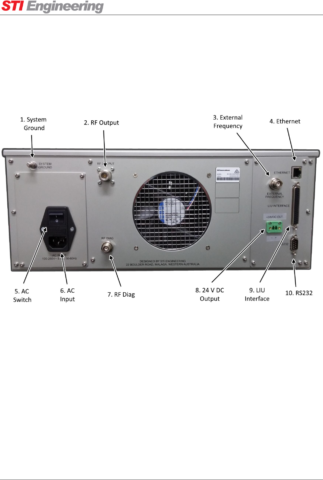
The back panel of the AC model paging transmitter is shown below in Figure 1.
Figure 1: Paging Transmitter Back Panel (AC model shown)
1. System Ground: External connection for system ground. When connecting a 24 VDC supply the
negative line is connected to the system ground. When connecting a -48 VDC supply the positive
line is connected to the system ground
2. RF Output: Modulated RF output from the paging transmitter. N-type female connector.
3. External Frequency: External reference input for accurate channel synthesis. BNC female
connector.
4. Ethernet: Ethernet connection for configuration and diagnostics over UDP. RJ45 connector. The
Ethernet cable from the RFI-148/900250 to the Ethernet switch must be less than 10 metres long.
5. AC Switch: Power switch.

Appendix A Technical Specifications
RFI-148 & RFI-900 High Output Power Paging Transmitters User Manual Page 9 of 99
6. Power Supply Input: The power supply input is model-specific. The AC input connector is shown in
Figure 1.
a. 24VDC Model: 20 to 31.2 VDC input range for 24 V nominal. Phoenix terminal block
connector.
b. -48VDC Model: -40.5 to -57 VDC input range for -48 V nominal. Phoenix terminal block
connector.
c. 110/240VAC Model: 100 to 250 VAC, 50 to 60 Hz
7. RF Diag: Sniffer port for diagnostics. TNC female connector.
8. 24V DC Output (RFI-900 only): Enabled via Cruise Control (Encoder Interface → 24 V DC
Output), the RFI-900 can source up to 2A at 24V to an external load. Phoenix terminal block
connector (plug supplied).
9. LIU Interface: Combined alarm and encoder interface. DC-37 female connector.
10. RS-232: Rear serial port.
a. RFI-148: DE-9 male connector (DTE)
b. RFI-900: DE-9 female connector (DCE).
2.3.1 Installation Guidelines to Ensure Safe Exposure Levels
The following installation guidelines ensure that safe exposure levels to radio frequency radiation are not
exceeded:
1. Ensure the unit is switched off, and the mains power supply is unplugged.
2. Properly connect antennas, and RF cabling.
3. Connect other cabling, leaving power cables last.
4. Ensure that the safe distance limits in Table 1 are met before powering and operating the unit, using
physical exclusion barriers if necessary.
Appendix A Technical Specifications
RFI-148 & RFI-900 High Output Power Paging Transmitters User Manual Page 10 of 99
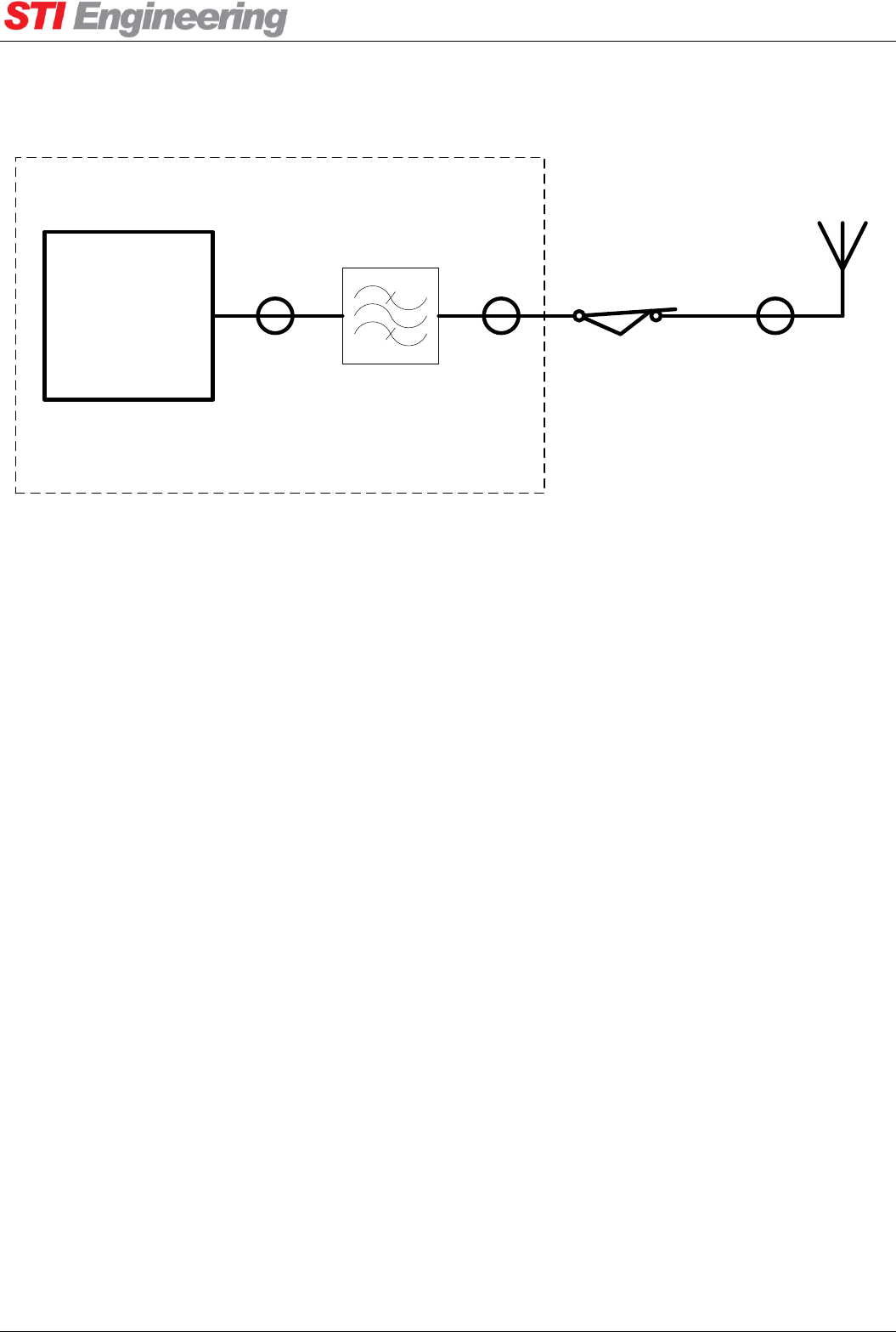
2.3.2 Typical Installation
RFI-148/900 250
Paging
Transmitter
Inside weather-proof structure
2 m EUPEN 5092-
HFLR cable 5 m LDF4-50
cable
30 m LDF4-50
cable
Huber+Suhner
3401 series
lightening
protector
Band-pass
cavity filter
Antenna
Figure 2: Typical installation components
In a typical installation the RFI-148/900 250 will be housed in a weather-proof structure. Inside the weather-
proof structure a 2 m EUPEN 5092-HLFR cable will connect the antenna port of the RFI-148/900 250 to the
input of a band-pass cavity filter (CV1417-0111-11 for RFI-148 or CV9296-0511-11 for RFI-900) . A 5 m
run of LDF4-50 cable will connect to the output of the band-pass cavity filter, exit the weather-proof
structure into the input of a Huber+Suhner 3401 series lightening protector mounted on the outside of the
weather-proof structure. A 50 m run of LDF4-50 cable will connect to the output of the Huber+Suhner 3401
series lightening protector, run across to a 30 m antenna tower via a cable tray, then run up the tower to an
antenna (COL54 for RFI148 or COL806 for RFI-900) mounted at the top. The installation is completely
fenced off and secured with lock and key.
Appendix A Technical Specifications
RFI-148 & RFI-900 High Output Power Paging Transmitters User Manual Page 11 of 99
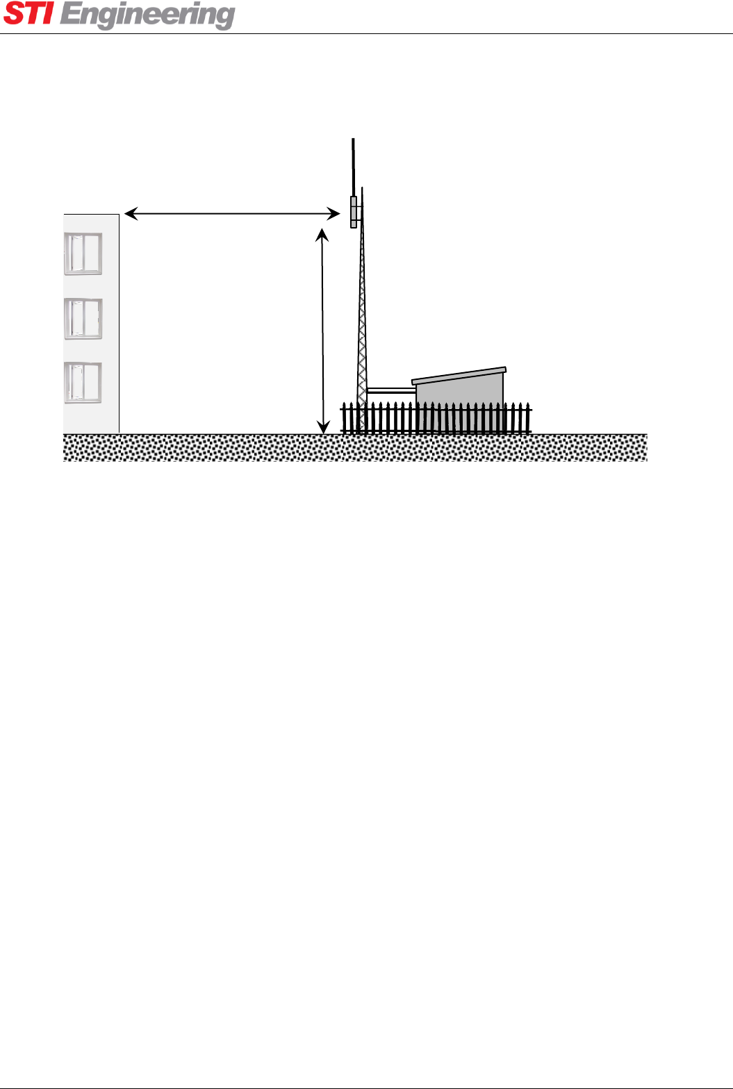
Figure 3: Typical installation site
Weather-proof
structure containing
RFI-148/900 250
paging transmitter
Antenna
height ≈
30 m
Antenna
A clear installation will provide optimal radio signal propagation.
High rise building distance > 40 m
Installation is completely
fenced off.
Appendix A Technical Specifications
RFI-148 & RFI-900 High Output Power Paging Transmitters User Manual Page 12 of 99
2.4 Safety and Compliance
This device complies with Part 15 of the FCC Rules. Operation is subject to the following two conditions:
(1) This device may not cause harmful interference, and (2) this device must accept any interference
received, including interference that may cause undesired operation.
2.4.1 Human Exposure to Emissions, Safe Distances
RF radiation source
Safe distance
Notes
RFI-148/900 250 mechanical enclosure
> 15 cm
Transmit signal RF cabling
> 15 cm
Antenna < 6 dBi gain
> 7 m
These distances are used to
determine the minimum
antenna height and distance
to nearest high-rise
habitable structures
Antenna < 8 dBi gain
> 8 m
Antenna < 10 dBi gain
> 10 m
Antenna < 12 dBi gain
> 13 m
Antenna < 14 dBi gain
> 16 m
Table 1: Human exposure to emissions, safe distances
For further information on human RF exposure, contact your local health department. For example, Health
Canada’s Safety Code 6 provides a comprehensive set of Canadian guidelines.
2.4.2 Equipment Installation
Any devices that connect to the data ports must comply with clause 4.7 of EN 60950-1.
The installation should be in accordance with EN 50310:2010.
2.4.3 Modifications
CAUTION: Changes or modifications not expressly approved by STI Engineering will void the user’s
authority to operate the equipment legally, as well as any warranty provided.
Appendix A Technical Specifications
RFI-148 & RFI-900 High Output Power Paging Transmitters User Manual Page 13 of 99
3. Configuration
3.1 Overview
There are six interfaces available for configuration and diagnostic information to be monitored:
Cruise Control management interface: All configuration and diagnostics parameters can be
accessed using the Windows-based Cruise Control Graphical User Interface (GUI).
SNMP interface: Support for diagnostics using SNMP through the RFI SNMP Proxy agent.
Terminal menu interface: A navigable menu system is available that has all the configuration and
diagnostics that Cruise Control provides.
AT command interface: The AT command interface provides a subset of the configuration and
diagnostic information available over Cruise Control with ASCII Hayes attention commands. For a
list of AT commands see Appendix D Hayes AT Reference.
Front panel interface: The front panel consists of six status LEDs and a transmit power gauge.
LIU interface: The combined LIU interface has digital inputs and alarm outputs for limited
configuration and diagnostic output.
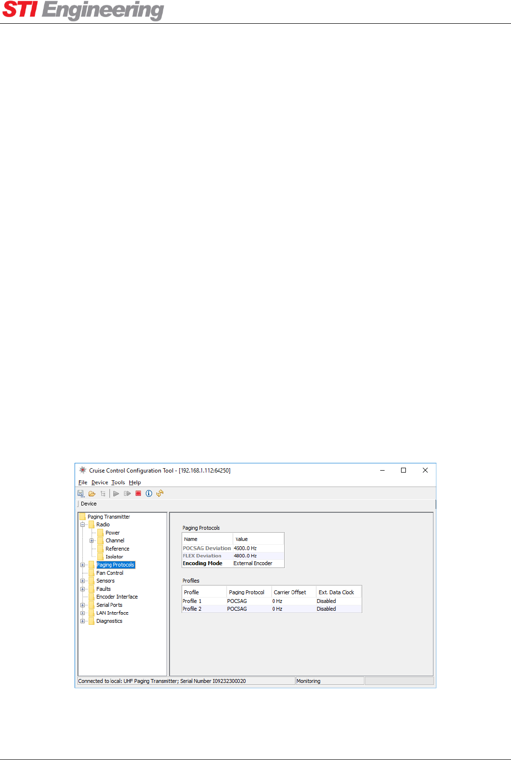
3.2 Cruise Control
This section outlines how to use Cruise Control with the paging transmitter. For more information see the
Cruise Control User Manual. Figure 4 below is a screenshot of Cruise Control running on Windows 10.
Figure 4: Cruise Control Interface

Appendix A Technical Specifications
RFI-148 & RFI-900 High Output Power Paging Transmitters User Manual Page 14 of 99
3.2.1 Installation
The requirements for using the Cruise Control application are:
Pentium III+ Processor.
Windows XP (x86) or Windows 7 (x86 and x64).
At least 1 available serial port or a network connection to the device.
3.2.2 Connecting to the Paging Transmitter
SERIAL
To connect to a device with RS-232, attach the paging transmitter to the PC running Cruise Control via a
serial port. Configure the Cruise Control communication settings using Device -> Configure
Communications, ensure that Serial is selected from the dropdown box and enter in the serial settings
(The front serial port is locked to 19200 8N1).
Use the Device -> Connect to Local Device menu item to connect to the local device.
ETHERNET
To connect to a device over a network, the device IP address must be known. Configure the Cruise Control
communication settings using Device -> Configure Communications, ensure that UDP is selected
from the dropdown box and enter the device IP address. For the UDP port, enter 64250, 64251 or 64252.
The paging transmitter listens on UDP ports 64250, 64251 and 64252 for data and will not allow more than
one simultaneous session per port. If the paging transmitter does not respond to Cruise Control on a UDP
port, try another port as a connection could already be active on that port.
Use the Device -> Connect to Local Device menu item to connect to the device.
3.2.3 Device Navigation
Once all the settings have been downloaded from the device, the available configuration groups are
displayed in a tree on the left. Items that can be configured in each group are displayed in tables on the right.
The names of editable items are displayed in black. Read only items have their names in grey.
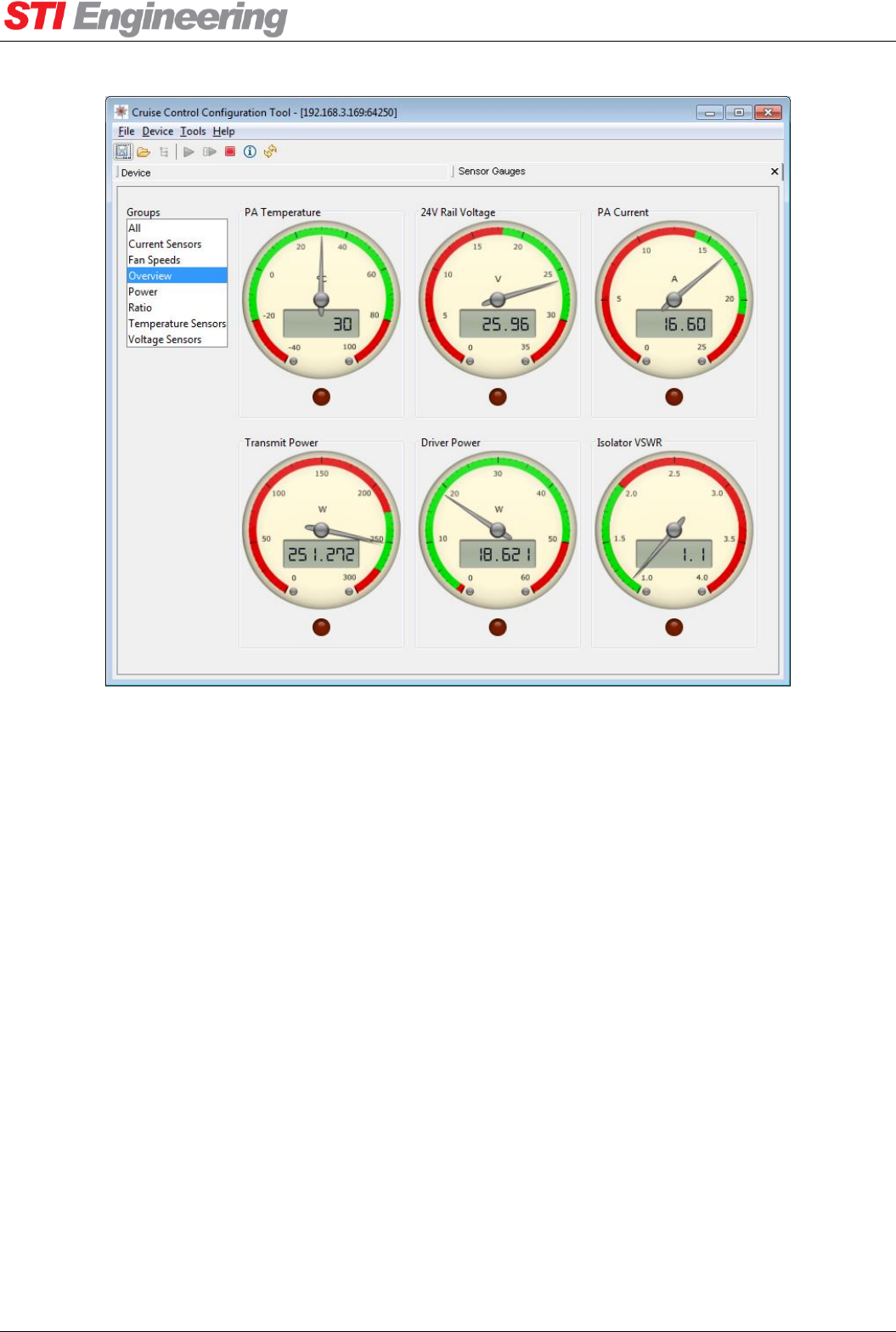
3.2.4 Sensor Gauges
Cruise Control can provide real-time operational information for paging transmitters using the Sensor
Gauges plugin. A screenshot of the Sensor Gauges plugin is shown below in Figure 5.
Appendix A Technical Specifications
RFI-148 & RFI-900 High Output Power Paging Transmitters User Manual Page 15 of 99
Figure 5: Cruise Control Sensor Gauges Plugin
To view Sensor Gauges for a paging transmitter, first connect to the paging transmitter using Cruise Control.
Then use the Tools -> Plugins -> Sensor Gauges menu item to open the Sensor Gauges plugin.
The Sensor Gauges will automatically update, with the needles showing the current value of the gauge
parameter. The green region indicates the expected normal operating value for the parameter. The upper and
lower cut-off values for the sensor (see section 0) determine the range of the green region. There is a red
indicator below each gauge which turns on when the parameter exceeds the upper or lower cut-off value.
The Groups option box on the left shows the different groups of gauges available, grouped by the unit of
measurement of the sensor. There are also two additional groups, overview and all. The overview group
provides a subset of the most informative gauges for quick diagnostic troubleshooting. The all group shows
all of the gauges.
3.2.5 Firmware Update
Cruise Control supports the updating of device firmware. Cruise Control will only allow firmware images
that are compatible with the paging transmitter to be uploaded. For more information, see section 0.
Appendix A Technical Specifications
RFI-148 & RFI-900 High Output Power Paging Transmitters User Manual Page 16 of 99
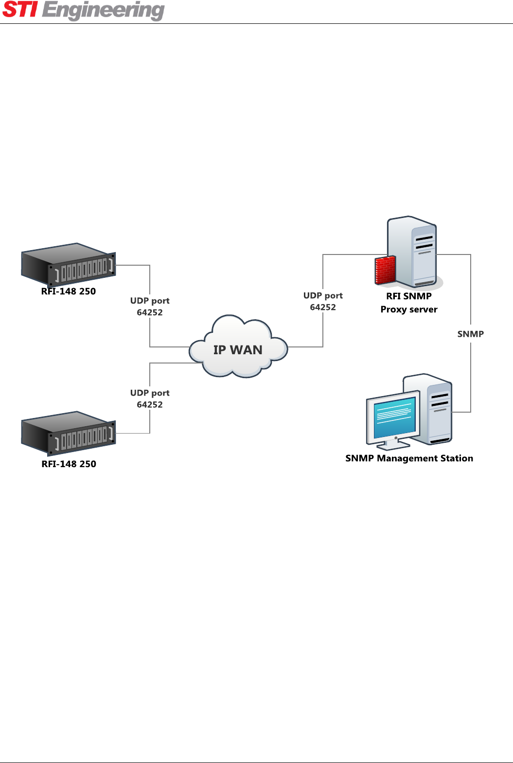
3.3 SNMP
RFI SNMP Proxy is an SNMP agent which allows configuration and diagnostics via SNMP. RFI SNMP
Proxy can be installed on a Windows or Debian Linux system, including embedded devices capable of
running Linux.
In smaller networks, RFI SNMP Proxy may be run on the same machine as an SNMP network monitoring
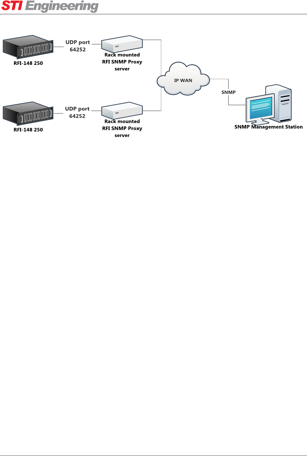
application. SNMP communication may be done via IP loopback as shown in Figure 6. Alternatively, RFI
SNMP Proxy may run on existing embedded devices connected to the transmitter by Ethernet, as shown in
Figure 7.
Figure 6: RFI SNMP Proxy running on a central server
SNMP versions 1 and 2c are supported. The community string ‘public’ should be used when issuing SNMP
requests. RFI SNMP Proxy is compatible with standard SNMP managers and other SNMP client
applications. An SMI MIB file defining OIDs for this product is available from STI Engineering.
RFI SNMP Proxy communicates with the paging transmitter via a proprietary protocol using UDP port
64252 through the Ethernet interface.
Not all configuration and diagnostic parameters may be accessed via SNMP. See Appendix C.2 for a list of
values which may be accessed via SNMP.
Appendix A Technical Specifications
RFI-148 & RFI-900 High Output Power Paging Transmitters User Manual Page 17 of 99
Figure 7: RFI SNMP Proxy running on embedded hardware on remote sites
3.4 Terminal Menu Interface
The terminal menu provides access to all configuration parameters in the radio.
To access the terminal menu execute the AT? command at the Hayes AT command interface. See section 3.5
on page 17 for information on executing AT commands. The terminal menu will not be started if it is open
on another port, instead the BUSY response is returned.
The terminal menu is available over serial, UDP (ports 64250 and 64251) and TCP (port 23).
3.5 Hayes AT Command Interface
The paging transmitter supports Hayes ATtention commands. These are used to query and change device
configuration and probe performance parameters. AT commands are available via serial port, and via TCP
port 23 on the Ethernet interface.
The format for the query and configuration AT command is:
ATxxx<[I1, I2, … In]><=value><TERM>
Where:
AT is the attention code. All AT commands must be prefixed with AT. This is case insensitive, so
At, aT, or at can also be used.
xxx is the actual command. The list of valid AT commands is given in Appendix D on page 54.
<[I1, I2, … In]> is an optional section that allows the specification of an index. Indexes are
used to access one of an array of similar items. For example, the paging transmitter has a list of
sensor values which can be accessed using the ATI90 indexer. The command ATI90[0] will
read the PA temperature, while the command ATI90[1] will read the driver temperature.
<=value> is an optional section that is used to set the value of a configuration parameter. If this
section is omitted, then the value of the configuration parameter will be displayed.
<TERM> is the terminator for the AT command. A terminator can consist of a carriage return
(ASCII value 13Decimal) or a carriage return followed by a line feed (ASCII value 10Decimal).

Appendix A Technical Specifications
RFI-148 & RFI-900 High Output Power Paging Transmitters User Manual Page 18 of 99
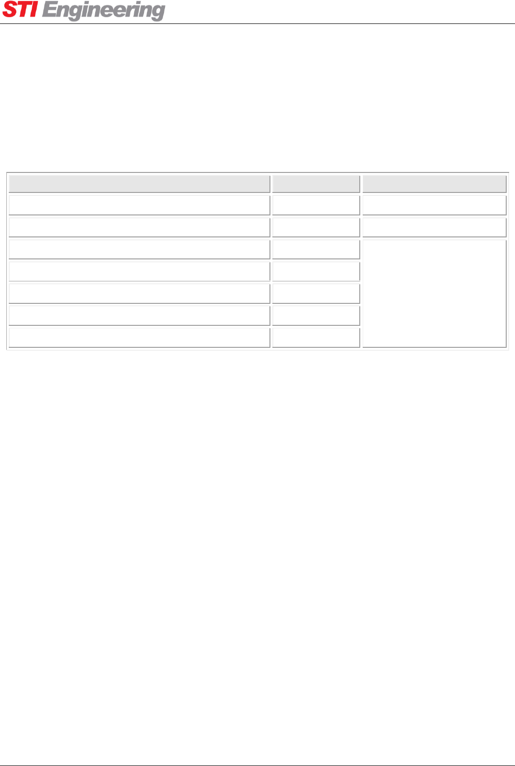
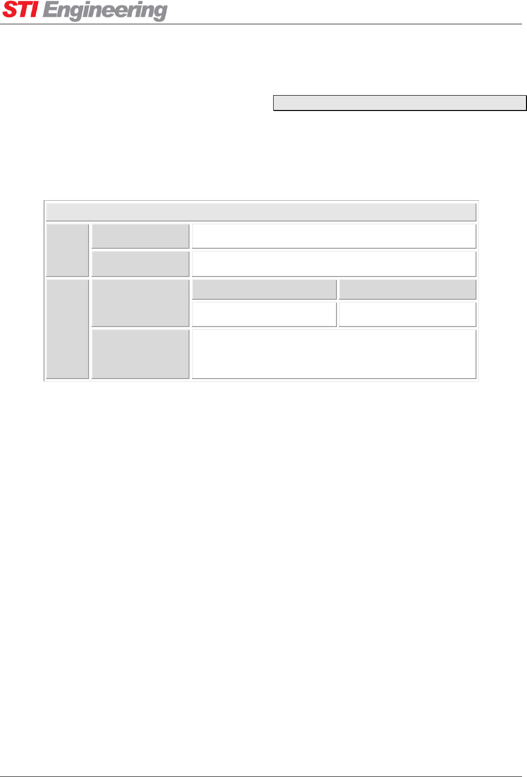
A response is generated for each AT command issued. Responses to AT commands are shown in Table 2.
Response
Code
Response
Number
Description
OK
0
Returned whenever a command is entered that is executed correctly.
ERROR
4
Returned whenever a command is invalid or could not be executed.
BUSY
7
Returned when an attempt is made to enable the menu via AT? but the menu
system is already enabled on the other serial port.
Table 2: AT command response codes
3.5.1 List Slicing Syntax
Multiple indexes of an indexer can be queried in a single AT command using the list slicing syntax. AT
command sets cannot be used with the list slicing syntax. The list slice syntax uses the colon ‘:’ operator to
indicate a range of indexes to retrieve. Each value retrieved is printed on a new line.
For example, the AT command for retrieving a single sensor value is I90[n] where n is the index of the
sensor. To retrieve the first four sensor values (PA, Driver, PA Ambient, and Isolator temperatures) the
following syntax can be used:
Figure 8: List slicing syntax on the current sensor value
Running the list slice operator ‘:’ without specifying the range will return the length of the indexer:
Figure 9: List slicing syntax for the length of an indexer
3.5.2 Sequenced AT Commands
A series of get AT commands can be concatenated into a single AT command, known as a sequenced AT
command. AT command sets cannot be sequenced. A sequenced AT command begins with the attention
code, AT, followed by a number of commands, followed by the terminator.
For example, the AT commands for the serial number, current channel, and main serial port baud rate are I6,
S54 and S100[0], respectively. These commands can be run separately:
ATI90[0:3]
45
42
39
30
OK
ATI90[:]
27
OK

Appendix A Technical Specifications
RFI-148 & RFI-900 High Output Power Paging Transmitters User Manual Page 19 of 99
Figure 10: Separate AT commands
Alternatively, they can be concatenated and run as a sequenced command:
Figure 11: Sequenced AT command
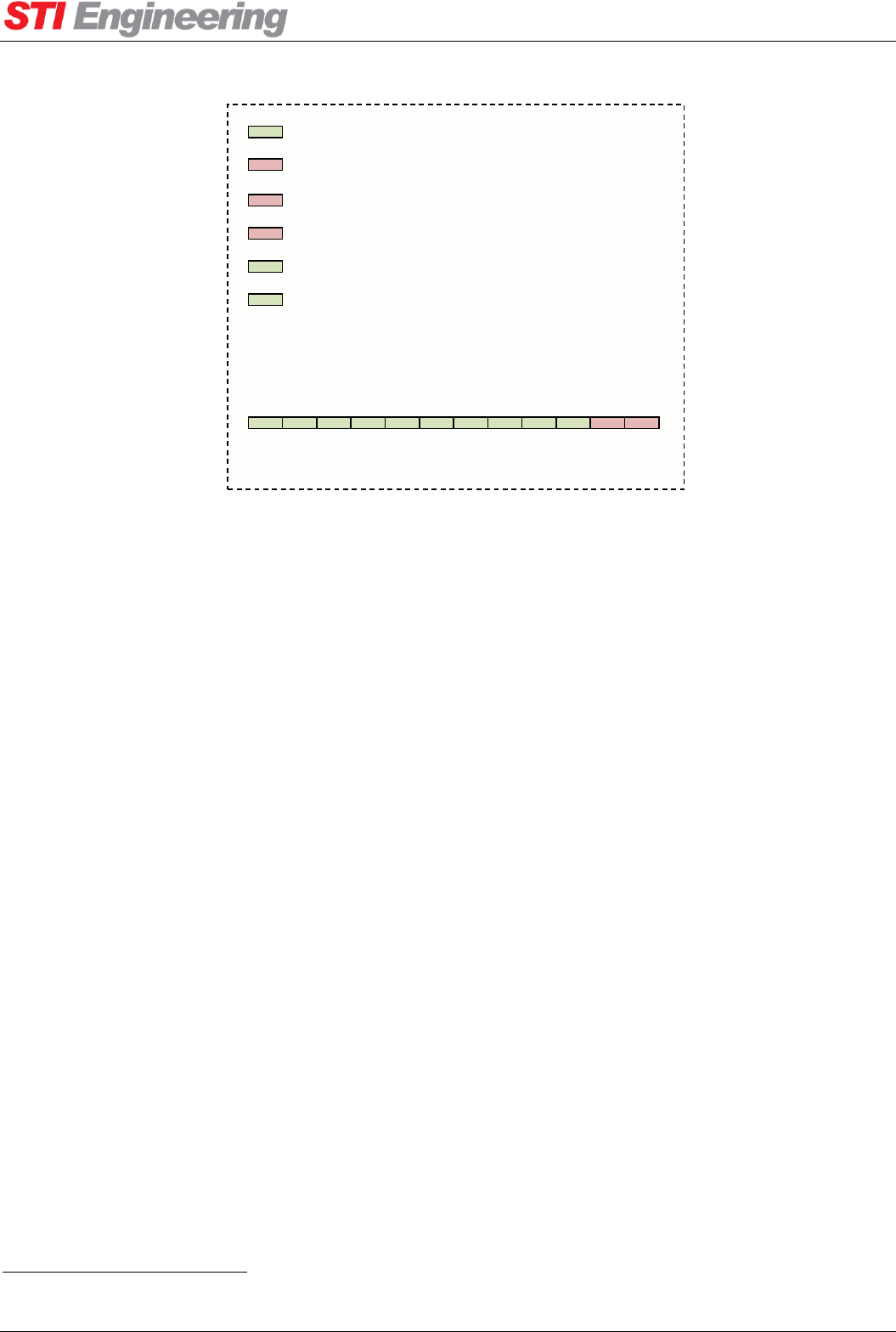
3.6 Front Panel Interface
The front panel interface consists of six status LEDs and a transmit power gauge. The panel is illustrated in
Figure 12 and the function of each LED is described in Table 3.
LED
Colour
Description
Transmit On
Green
Turns on when the transmitter is on.
Fault
Red
Turns on when any fault is active. Will flash in unison with the
Serial/Ethernet LED if there are serial errors.
Low Power
Red
Turns on when the sensed transmit power is lower than the
lower cut-off value as specified in the sensor parameters.
High VSWR
Red
Turns on when the isolator VSWR is higher than the higher cut-
off value as specified in the sensor parameters.
Serial/Ethernet
Green
Flashes when serial or Ethernet data is transmitted or received.
Power
Green
Turns on/off at 1 Hz while power is supplied.
Power Gauge
Green/Red
A bar graph displaying current transmit power.
Table 3: Front panel LED descriptions
ATI6
F00012K01000
OK
ATS54
1
OK
ATS100[0]
8
OK
ATI6S54S100[0]
F00012K01000
1
8
OK
Appendix A Technical Specifications
RFI-148 & RFI-900 High Output Power Paging Transmitters User Manual Page 20 of 99
TRANSMIT ON
FAULT
LOW POWER
HIGH VSWR
SERIAL/ETHERNET
POWER
25
250
125
TX POWER (W)
Figure 12: Front Panel Display
3.7 LIU Interface
The LIU interface is a DC-37 female connector at the rear of the paging transmitter. The pin-out for the LIU
Interface can be found in Appendix A.4. The LIU interface has nine digital inputs
1
and fourteen alarm
outputs. The alarm outputs are numbered 1 to 13 with an additional combined alarm and are configurable.
The digital inputs are:
Frequency Select 1
Frequency Select 2
Frequency Select 3
Frequency Select 4
Protocol Select
Hardware PTT
Tx Data L-bit
Tx Data H-bit
Transmit Clock
Aux Input 1 (RFI-148 only)
Use of the hardware PTT, protocol select and frequency select inputs are all optional and may be disabled in
software. The use of the transmit clock is optional for 2-level protocols, but required for 4-level protocols.
1
RFi-148 has an extra, general purpose input “Aux Input 1,” for a combined total of 10.
Appendix A Technical Specifications
RFI-148 & RFI-900 High Output Power Paging Transmitters User Manual Page 21 of 99
4. Operation
4.1 Serial Port Operation
4.1.1 Overview
The RFI-148/900250 has two RS-232 serial ports, providing support as shown in Table 1. The serial port
pin-outs can be found in Appendix A.3 on page 45.
Serial Ports
Front
Connector Type
Female DE9 (DCE)
Supported
TX, RX, GND.
Rear
Connector Type
RFI-148
RFI-900
Male DE9 (DTE)
Female DE9 (DCE)
Supported
TX, RX, and GND,
RTS and DTR outputs
CTS and DCD inputs
Table 4: Serial port availability.
4.1.2 Configuration
The rear serial port supports the following configuration options:
Baud rate: 300, 600, 1200, 2400, 4800, 9600, 19200, 38400, 57600 or 115200.
Data bits: 7 or 8.
Parity: None, odd, or even.
Stop bits: 1 or 2.
The front serial port is locked into a specific configuration to ensure a fail-safe way to communicate with the
paging transmitter:
Baud rate: 19200.
Data bits: 8.
Parity: None.
Stop bits: 1.
4.1.3 Statistics
Statistics are maintained for both serial ports. These statistics are listed in Table 21 in Appendix C.1. All
statistics are reset if power is removed.
Serial Ports -> [Rear|Front] Settings

Appendix A Technical Specifications
RFI-148 & RFI-900 High Output Power Paging Transmitters User Manual Page 22 of 99
These statistics may be useful in troubleshooting. For example, Rx framing errors may indicate that the
serial port configuration does not match the serial port configuration of the link partner.
4.2 Ethernet Operation
4.2.1 Overview
The paging transmitter has one 10BASE-T/100BASE-TX Ethernet port. Auto-negotiation of link speed is
supported, including duplex mode. There is also a software override for forcing the parameters of the link.
4.2.2 IP Addressing
The paging transmitter supports IPv4. The paging transmitter may have a statically assigned IP address or
obtain an IP address as a DHCP client.
A static IP address may be configured with a single static address. A subnet mask and default gateway may
be configured to allow communication across sub-networks.
The paging transmitter may act as a DHCP client. This allows a DHCP server to assign an IP address to the
paging transmitter. By default, the DHCP client is enabled and the hostname of the paging transmitter is of
the form “rfi-serial_number” where serial_number is the factory assigned serial number of the unit. If the
unit does not receive an IP address from the DHCP server, the IP interface will not work.
4.2.3 Statistics
Both IP and Ethernet packet statistics are independently recorded and presented as combined figures for all
active data streams since the transmitter was last powered-up. A power-cycle of the transmitter clears this
data.
4.3 Transmitter Operation
4.3.1 Transmit Power
The RFI-148/900250 supports transmit power from 20 to 250 Watts in 1 Watt increments.
POWER FOLDBACK
The power foldback is a configurable percentage which calculates the power to foldback to when the scale
transmit power fault action is latched. For example, for a transmit power of 250 W and a power foldback of
50%, the transmitter will transmit at 125 W when the scale transmit power fault action is latched. See section
5.2.1 for more information on fault actions.
4.3.2 Channel Selection
The RFI-148/900250 has up to sixteen radio channels. Each channel represents a transmit frequency.
LAN Interface
Radio -> Power
Radio -> Channel
Appendix A Technical Specifications
RFI-148 & RFI-900 High Output Power Paging Transmitters User Manual Page 23 of 99
The channel frequencies can be set anywhere within the radio switching bandwidth, but must equal integer
multiples of the raster frequency.
The channel to be used can be set by
adjusting the current channel setting.
ENCODER CHANNEL CONTROL
The active channel can be set by adjusting the current channel setting in software. Alternatively, “Encoder
Channel Control” may be enabled and the channel set through the LIU interface as shown in Table 5 below.
If encoder channel control is used, the channel cannot be changed in software.
Channel
CH4
CH3
CH2
CH1
1
N/C
N/C
N/C
N/C
2
N/C
N/C
N/C
Gnd
3
N/C
N/C
Gnd
N/C
4
N/C
N/C
Gnd
Gnd
5
N/C
Gnd
N/C
N/C
6
N/C
Gnd
N/C
Gnd
7
N/C
Gnd
Gnd
N/C
8
N/C
Gnd
Gnd
Gnd
9
Gnd
N/C
N/C
N/C
10
Gnd
N/C
N/C
Gnd
11
Gnd
N/C
Gnd
N/C
12
Gnd
N/C
Gnd
Gnd
13
Gnd
Gnd
N/C
N/C
14
Gnd
Gnd
N/C
Gnd
15
Gnd
Gnd
Gnd
N/C
16
Gnd
Gnd
Gnd
Gnd
Table 5: Channel selection via LIU Interface
4.3.3 Push-To-Talk (PTT)
There are three methods available to turn the transmitter on:
Software PTT: Software PTT is available using Hayes AT commands, through the Cruise Control
GUI, or through the terminal menu interface. It is also selected implicitly when enabling TNPP or
PET/TAP on either a serial or Ethernet stream.
Encoder Interface -> Encoder Channel Control
Appendix A Technical Specifications
RFI-148 & RFI-900 High Output Power Paging Transmitters User Manual Page 24 of 99
Hardware PTT: Hardware PTT is available through the LIU connector. Hardware PTT can be
configured to be active high or active low. The delay from hardware PTT to transmitter on and data
ready is 10 ms.
Auto PTT: Auto PTT is performed by detecting a change in the data bits on the LIU and turning on
the transmitter. When using auto PTT some preamble will be lost; some encoders may need to
increase preamble time.
Hardware PTT can be enabled using the “Encoder Hardware PTT” option and auto PTT can be enabled
using the “Auto PTT” option in the “Encoder Interface” menu. Hardware PTT and auto PTT cannot both be
enabled at the same time.
PTT TURN OFF DELAY
The unit has the option to leave the transmitter on for a set duration after receiving a PTT off signal. This
delay is driven by software and typically accurate to 100 ms.
TRANSMIT TIMEOUT
The unit can automatically raise a fault if the transmitter has been transmitting for too long. By default, the
transmit timeout feature is disabled. If enabled, the transmit timeout fault causes the transmitter to key down
and set the PTT system override to disable transmit. See section 5.2.1 for
more information on fault actions.
PTT OVERRIDE
Transmitter PTT can be completely disabled which stops the paging transmitter from transmitting. PTT
override can be changed using the “PTT override” setting.
In some cases the paging transmitter will disable itself from transmitting. If PTT override is disabling
transmit the “PTT Override Status” will describe what caused the override. There are five circumstances
where the paging transmitter will override PTT:
User: The PTT override has been configured to “Disable Transmit”.
Listening: The isolator mode is set for listening (for operation of the isolator see section 0).
Fault: The disable transmit fault action is active (for more on fault actions see section 0).
Loading Config: Cruise Control is loading a configuration file.
In Standby: The unit is in Standby due to the Hot Standby operation (see section 7 Hot Standby
Operation).
PTT is enabled once the source of the override is addressed.
Radio -> PTT Turn Off Delay
Radio -> Transmit Timeout
Radio -> PTT Override

Appendix A Technical Specifications
RFI-148 & RFI-900 High Output Power Paging Transmitters User Manual Page 25 of 99
HARDWARE PTT EDGE OR LEVEL DETECTION
The transmitter keys up due to the rising or falling edge of the hardware PTT signal – it is based on edge
detection rather than sampling. However, there are three exceptions to this case where the hardware PTT
signal is sampled to check for key up:
When the unit powers up.
When the hardware PTT configuration is changed from Disabled to Enabled.
When the unit comes out of PTT Override.
4.3.4 External Reference
The transmitter supports an external reference for channel frequency generation.
To use the external reference, a 5 or 10 MHz sine or square wave -20 dBm to +15 dBm signal must be
applied to the “External Frequency” input BNC connector on the back panel. The “Reference Mode” must
then be configured to “External With Failover”. The paging transmitter will use the internal reference by
default.
The external reference frequency must be configured correctly in order to lock to the external reference. By
default the external reference is configured to 10 MHz.
AUTOMATIC REFERENCE SWITCHOVER
If the external reference is selected as the default reference, the transmitter will switch to the internal
reference in the event of the external reference failing. There are two conditions which characterise an
external reference failure:
The external reference is not detected. The external reference won’t be detected if it is less than the
specified input power.
Cannot lock to external reference. If the frequency difference between the internal and external
reference drifts too far, the paging transmitter will not lock to the external reference.
NOTE: If the paging transmitter is transmitting when
reference switchover occurs, there may be data loss.
4.3.5 Absolute Delay Adjustment
The paging transmitter can insert a small artificial delay on data presented on the LIU interface before it is
passed to the digital synthesiser. The delay adjustment can be set from 0 to 40 ms in 5 µs steps. The
additional net delay is accurate to 3 µs.
Absolute delay adjustment can be used for matching delay in:
Simulcast networks where transmitters from different manufacturers are used.
Radio -> Reference
Radio -> Absolute Delay Adjustment

Appendix A Technical Specifications
RFI-148 & RFI-900 High Output Power Paging Transmitters User Manual Page 26 of 99
Radio and leased line simulcast systems.
4.3.6 RF Diagnostics
The paging transmitter provides an RF diagnostics port output on the back panel. The RF diagnostics port
can be configured for two different modes using the “Isolator Mode” setting:
Set for Transmitting: The RF diagnostics port will output a signal identical to that of RF out but at a
much lower power level.
Set for Listening: Insertion loss from RF out to RF diag is decreased to 12 dB. This is a special mode
of operation used for network testing. NOTE: While in listening mode, PTT override is forced to
disable transmit.
LISTEN MODE TIMEOUT
A timeout can be enabled for listening mode. When the listening mode timeout is enabled, the isolator mode
will automatically revert to transmitting mode after the timeout expires. The timeout starts when the isolator
mode is set to listening mode. By default, the listening mode timeout is disabled.
ISOLATOR FEEDBACK
The isolator feedback is a read-only field that indicates the isolator status when the isolator is in listening
mode. When the isolator mode is set to listening, the feedback status will change to “Switching” for one
second and then change to “Listening Mode”. However, if the status changes to “Listening Failure” then
there may be a hardware failure of the mechanical attenuation switch-out.
4.4 Data
The RFI-148/900250 supports the following modulation formats:
POCSAG: Baud rates of 512, 1200 and 2400 bps (2-level FSK) are supported.
FLEX: Baud rates of 1600 (2-level FSK), 3200 (2-level or 4-level FSK) and 6400 bps (4-level FSK)
are supported.
Custom: A customizable deviation and FSK level at baud rates up to 6400 bps. See section 0.
2-level FSK protocol data may optionally be clocked into the paging transmitter using the external data
clock or may run asynchronously. 4-level FSK
protocols must use the external data clock.
4.4.1 4-Level Deviation Mapping
When using 4-level FSK the deviation with respect to the H and L bits is outlined in Table 6 below. Note
that two interpretations of the H-bit/L-bit are available, denoted as “Legacy” and “Normal” and configurable
Radio -> Isolator
Encoder Interface -> 4-Level Operation
Appendix A Technical Specifications
RFI-148 & RFI-900 High Output Power Paging Transmitters User Manual Page 27 of 99
via Encoder Interface → 4-Level Operation. The “Legacy/Normal” operation was introduced in firmware
4.0, firmware versions prior to this operate implicitly in “Legacy” mode.
H-Bit
L-bit
Deviation from Carrier (Hz)
Legacy
Normal
N/C
N/C
+
𝐹
𝑑
3
+
𝐹
𝑑
3
N/C
Gnd
+ 𝐹
𝑑
−
𝐹
𝑑
3
Gnd
N/C
−
𝐹
𝑑
3
+ 𝐹
𝑑
Gnd
Gnd
−𝐹
𝑑
−𝐹
𝑑
Table 6: Custom 4-level deviation frequency offsets
Where 𝐹
𝑑 is the deviation
frequency in Hz.
4.4.2 Carrier Offset
The carrier offset setting is provided for use in simulcast paging networks. The offset from the carrier
frequency can be specified for each protocol. The carrier offset can be set from +5000 to -5000 Hz in
increments of 1 Hz.
4.4.3 Custom Deviation
The transmitter supports generation of non-standard paging protocol settings. When the paging protocol
custom is selected, the custom deviation and FSK level are used for that protocol. The custom deviation
setting is useful for legacy paging systems with non-standard protocols and/or paging
receivers.
4.5 Fan Control
The transmitter has two fans for cooling; the front fan is an intake and the rear fan is the exhaust. The fans
turn on at the configured fan turn on temperature, and then turn off at the configured fan turn off
temperature. The temperature reference is configurable to either individual sensors, the hottest of all sensors,
or the hottest of all sensors on the PA and Isolator (‘PA Group Sensors’).
4.5.1 Fan Override
There is a fan override feature available to force the fans to turn on at full speed. When fan override is set to
always on the fans will turn on and ignore the reference temperature.
Paging Protocols -> Profile [1|2] -> Carrier Offset
Paging Protocols -> Advanced
Fan Control

Appendix A Technical Specifications
RFI-148 & RFI-900 High Output Power Paging Transmitters User Manual Page 28 of 99
4.5.2 Self-Test
The fan controller has a self-test feature which causes the fans to run at full speed for a minute so fan
operation can be verified. The self-test feature runs once every 24 hours by default.

Appendix A Technical Specifications
RFI-148 & RFI-900 High Output Power Paging Transmitters User Manual Page 29 of 99
5. Diagnostics
5.1 Status Monitoring
The paging transmitter has a number of sensors which are continuously monitored. The sensors are used to
monitor:
Internal voltage and current levels.
Ambient and transmitter temperature.
Fan operation.
Transmitted and reflected power.
Each sensor has configurable upper and lower cut-offs that will cause a fault when exceeded. For example, if
the driver temperature upper cut-off is exceeded, the high driver temperature fault will be set active.
A full list of sensors, units of measure, and range of values can be found in Appendix E.
5.1.1 Conditional Cut-off Checking
Some sensors are only compared against their upper and lower cut-offs under certain conditions, such as
when the transmitter is on. The following sensors have conditional cut-off checking:
During transmission:
Exciter current.
PA current.
Driver current.
Reverse power.
Transmit power.
Driver power.
Exciter power.
Isolator VSWR.
While the fans are turned on to full speed:
Front and rear fan current.
Front and rear fan RPM.
A sensor that falls outside its cut-offs while its checking condition is met will cause the respective fault to
become active. A non-latching fault will only be cleared once it has returned to within its cut-offs while its
checking condition is met. A latching fault must be cleared in software.
Sensors -> Sensor Configuration

Appendix A Technical Specifications
RFI-148 & RFI-900 High Output Power Paging Transmitters User Manual Page 30 of 99
5.1.2 Minimum and Maximum Sensor History
When a sensor exceeds a previous minimum or maximum value for that sensor, the new minimum or
maximum value is saved to non-volatile storage. The minimum and maximum sensor values also use the
conditional cut-off checking. For example, minimum and maximum transmit power values are only recorded
during transmission. The sensor history can be cleared to aid in
troubleshooting.
5.2 Faults
Undesirable operating conditions are reported using the faults feature of the paging transmitter. In most
circumstances the paging transmitter should not have any active faults. Active faults indicate incorrect setup,
a hardware issue or misconfiguration of the paging transmitter.
Faults can be in one of four states:
Inactive: The fault is inactive.
Fleeting: The source of the fault is currently active; however it has not been active longer than the
minimum fault duration setting.
Active: The source of the fault is currently active.
Latched:
o For Faults: The fault was previously active but the source of the fault is no longer present.
o For Fault Actions: The fault action has been carried out.
A list of possible faults can be found in Appendix E.
5.2.1 Fault Actions
Each fault can be configured to perform an action when the fault transitions from the inactive (or fleeting) to
the active or latched state. The actions that are taken due to a fault are called Fault Actions. There are five
fault actions:
Reference switchover: The paging transmitter switches to the internal reference.
Disable transmission: Any current transmission is interrupted, the transmitter is keyed down and
future transmissions are disabled.
Scale transmit power: Transmit power is reduced to a configured percentage. See section 0.
Enable PA current fold-back: The PA current fold-back is engaged.
Enable reverse power fold-back: The reverse power fold-back is engaged.
Faults -> Fault Configuration

Appendix A Technical Specifications
RFI-148 & RFI-900 High Output Power Paging Transmitters User Manual Page 31 of 99
Each fault action operates as a fault itself; therefore when a fault action is taken, it can be seen as latched in
the faults menu and logged in the fault history. Fault actions are latch-only and can only be cleared through
user intervention. Any actions performed are reverted once the fault action is cleared.
5.2.2 Fleeting Faults
The minimum fault duration parameter determines how long the source of a fault is active until it is reported
to the fault interface. A fault that does not reach the minimum fault duration will not be logged, activate a
hardware alarm or trigger a fault action.
5.2.3 Combined Fault
The combined fault is an optional fault that will become active if any fault within the combined fault set
becomes active. Each fault can be configured to be part of the combined fault set. The combined fault will
only become inactive when all of the faults in the combined fault set return to inactive. The combined fault
has a dedicated alarm output.
5.2.4 Hardware Alarm Outputs
A hardware alarm output can be assigned to each fault (see Appendix A.4 for the LIU interface pin-outs).
When the fault is in the active or latched state, the respective alarm will be set to active. Multiple faults can
share the same alarm output. The alarm output will only be set inactive if all of the faults that use that alarm
output are inactive.
A list of hardware alarms available can be found in section 3.7.
5.3 Remote Firmware Update and Snapshot
5.3.1 Update
The remote firmware update feature is used to upload a firmware image to a paging transmitter for feature
additions and/or bug fixes. Remote firmware update requires a Cruise Control connection to the paging
transmitter and a valid RFI-148/900250 firmware image file.
The firmware update process has two stages: uploading the firmware image to the paging transmitter and
applying the firmware image.
FIRMWARE IMAGE UPLOAD
To upload the firmware image to the paging transmitter first connect to the transmitter using Cruise Control.
In the Cruise Control interface select Device -> Load Firmware from the toolbar. In the new
window that appears, navigate to the directory where the firmware image file is located, select the file and
click Upload. The upload process is displayed on the status bar in Cruise Control, near the bottom right.
Once the upload is finished, the status will display “Monitoring”.
Note that at this point the firmware image has not been applied. The firmware image is kept in non-volatile
storage until it is required.
Diagnostics -> Firmware Update
Appendix A Technical Specifications
RFI-148 & RFI-900 High Output Power Paging Transmitters User Manual Page 32 of 99
Once the firmware image has been uploaded, at any later date the firmware image can be applied.
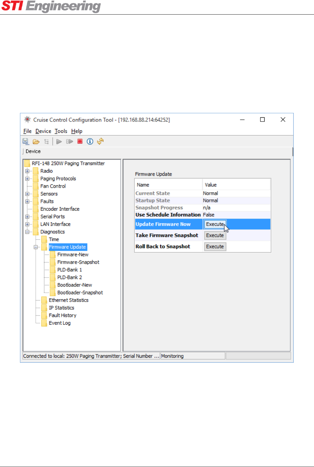
APPLYING FIRMWARE IMAGE
To apply an uploaded firmware image, run the “Update Firmware Now” routine. The paging transmitter will
reset to apply the image and will be unresponsive for up to one minute. Note that while the paging
transmitter is applying the firmware image, it will not transmit, respond to AT commands or connect with
Cruise Control.
Figure 13: “Update Firmware Now” routine
When the firmware starts up after applying the new image the “Version String” can be inspected to ensure
the new firmware image was loaded.
5.3.2 Snapshot
The paging transmitter has a firmware “Snapshot” used for recovering the paging transmitter to a previous
state. The snapshot contains a backup of the current firmware and configuration.

Appendix A Technical Specifications
RFI-148 & RFI-900 High Output Power Paging Transmitters User Manual Page 33 of 99
To create a snapshot, run the “Take Firmware Snapshot” routine. The paging transmitter will continue
operating normally during the snapshot process, which takes up to one minute to complete. The progress of
the snapshot is displayed in the “Snapshot Progress” field.
The snapshot can be reverted to at any stage. This can be useful to revert back to a ‘known good state’ if the
paging transmitter has been misconfigured or has been updated with an unwanted firmware update. To revert
to the snapshot run the “Roll Back to Snapshot” routine. The paging transmitter will reset and take up to
ninety seconds to revert back to the snapshot firmware and configuration. After reverting to a snapshot the
paging transmitter will start up with the firmware update exception fault latched to notify that the snapshot
was used.
By default, the paging transmitter has a factory snapshot that contains default factory firmware and
configuration.
5.4 Time
5.4.1 Real Time Clock
A battery-backed real time clock is used to track the passage of time. An accurate time is not essential for the
operation of the transmitter, but aids diagnostics and troubleshooting. The time is used for:
Generating time stamps for:
o The transmitter fault history.
o Firmware update images.
Transmitter uptime since power-up.
A short history of transmitter events (PTT on, off).
TIME ZONE
The time zone can be specified in hours and minutes as an offset from
Coordinated Universal Time (UTC).
5.4.2 SNTP Client
The transmitter supports time synchronisation using the Simple Network Time Protocol (SNTP) version 4.
The SNTP client can be disabled or set to unicast mode. In unicast mode, the paging transmitter will query
the configured time server for time updates at a configurable interval. By default the SNTP client is disabled.
Diagnostics -> Time
LAN Interface -> SNTP

Appendix A Technical Specifications
RFI-148 & RFI-900 High Output Power Paging Transmitters User Manual Page 34 of 99
6. Internal Encoding
6.1 Overview
The RFI PTX supports both internal and external page message encoding:
External Encoding: The historical and most common way of interfacing to the RFI PTX is by
clocking in pre-encoded paging data using the TTL inputs on the LIU. The RFI PTX will typically
interface with a Base Station Controller (BSC) that provides the encoded data.
Internal Encoding: The RFI PTX supports internal encoding of the POCSAG paging standard for
generating messages when submitted through the serial or Ethernet ports. Messages can be submitted
using the industry standard TNPP, TAP, or PET protocols. A custom protocol developed by STI
Engineering also provides an additional simple datagram protocol for submitting pages: “Page
Datagram”.
This section provides an overview of the internal encoding functionality.
When internal encoding is in use, the Hardware PTT and Auto PTT
functions are disabled.
6.2 POCSAG Settings
The RFI PTX has several options for the POCSAG protocol in order to support differing networks:
Preamble Length: The POCSAG preamble is used to wake up paging receivers and allow them to
lock to the incoming signal. A default value of 576 bits is used which is the de facto standard for
POCSAG.
Function Override: Allows the function bits in a POCSAG address codeword to be overridden to this
value. By default the function bits will follow the message encoding (00: Numeric, 01: Tone-only,
11: Alpha-numeric). The function bits have also been known as the “Group Code”.
Purge Timeout: The RFI PTX waits up until the purge timer in order to collate incoming page
subsmissions into a single large transmission. This saves on overhead of having to repeat the
preamble. Shorter Purge Timeouts will produce lower latency on page submission to transmission, at
the possible expense of
lower throughput when
sending many page
messages.
PAGE REPEATING
The RFI PTX supports a set of rules that trigger the repetition of a submitted page messages. When a rule is
enabled any messages which match the cap code will be repeated Count number of times every Delay
seconds.
Paging Protocols -> POCSAG
Paging Protocols -> POCSAG -> Page Repeat Rules

Appendix A Technical Specifications
RFI-148 & RFI-900 High Output Power Paging Transmitters User Manual Page 35 of 99
6.3 Protocols Supported
All protocols are accessible through either the rear serial port or the Ethernet port via TCP or UDP port
64250.
6.3.1 TNPP
The RFI PTX supports the ETE REQ and CAP PAGE block types. The TNPP station address is
configurable.
6.3.2 PET
The RFI PTX supports the PG1 and PG3 page submission types. Note that the page “zone” for PG3 has no
effect on the RFI PTX and it only accepts this value for backwards compatibility. Also accepted is a
password up to length 6 characters. The password is not checked and also exists only for backwards
compatibility.
There are several options available to allow for differences in PET implementations:
Line Separator: The RFI PTX can print either a carriage return (<CR>) or a carriage return and line
feed (<CR><LF>) for line separation. Note that the RFI PTX only accepts lines separated by <CR>.
Timeout: The timeout while expecting the next command string is configurable. The RFI PTX starts
a timer when it is expecting more data. If the timeout expires the RFI PTX PET parsing returns to
either the Idle or Logged In state.
Baud Rate: Due to PET not having a way to submit baud rate with page messages, the baud rate must
be pre-configured. Standard POCSAG baud rates of 512, 1200, and 2400 are supported.
Stay Logged In: This option allows the RFI PTX to remain in the Logged In state (ie, after the PG1
and password sequence) so messages can be submitted without having to handshake the connection
each time. This option can be used in conjunction with Implied Login to skip handshaking altogether.
Implied Login: If the <STX> character (the start of a message submission) is sent to the RFI PTX
this option allows the RFI PTX to transition directly to message submission state and skip the login
handshaking.
Detect Numeric Pages: Encode a paging message as numeric if all characters within the message fit
the numeric encoding scheme (ie, all characters are any of the following: '0', '1', '2',
'3', '4', '5', '6', '7', '8', '9', '!',
'U', ' ', '-', ']', '[').
6.3.3 TAP
The TAP protocol is treated the same as PET, however with some extensions:
Paging Protocols -> Encoding Mode
Paging Protocols -> TNPP
Paging Protocols -> TAP/PET
Paging Protocols -> TAP/PET

Appendix A Technical Specifications
RFI-148 & RFI-900 High Output Power Paging Transmitters User Manual Page 36 of 99
Group Code: The RFI PTX can be configured to accept a group code that trails the pager ID during a
message submission. The group code can be ‘A’, ‘B’, ‘C’, or ‘D’ when set for “Trailing Character”,
or ‘1’, ‘2’, ‘3’, ‘4’ when set to “Trailing Digit”.
6.3.4 Page Datagram
The Page Datagram protocol is request-response. The maximum datagram length including the sync and
CRC-32 fields is 265 bytes. Any datagrams larger than this will be dropped without response.
The general format of the protocol is (size in bytes of field shown in parenthesis):
Sync (1)
0xCA
Length (2)
Type (1)
Source
Address (2)
Sequence
number (2)
Packet-specific-data (x)
CRC-32 (4)
Header
Footer
Figure 14: Page datagram generic format
The general fields are:
Sync (1): The datagram sync byte, always 0xCA
Length (2): The length of the datagram, minus the 3-byte header (sync, length)
Type (1): The type of the page datagram, see below
Source Address (2): The address of the RTU to which the reply (if any) should be sent. This can be
set to 0xFFFF if unused
Sequence number (2): An incrementing sequence number for confirming replies. This can be set to 0
if unused
Packet-specific-data (x): Changes depending on the type field. Each type is shown in the following
section
CRC-32 (4): 32-bit CRC generated by the polynomial 0xEDB8832, with a starting value of
0xFFFFFFFF and the resulting value XOR’d with 0xFFFFFFFF. The CRC-32 is generated over the
whole datagram excluding the Sync and CRC field.
PAGE SUBMIT
Submits a page message for transmission by the RFI PTX. The format of the page submit packet is shown in
Figure 15.
<header>
Message
length (2)
Baud rate
(2)
Message (x)
<footer>
Page
class (1)
Cap code
(4)
Function
override (1)
Figure 15: Page submission packet format
The fields are:
<header>: The generic header shown in Figure 14 with the type field set to 0
Message length (2): The length of the “Message (x)” field (the only variable length portion of this
packet)
Paging Protocols -> Page Datagram

Appendix A Technical Specifications
RFI-148 & RFI-900 High Output Power Paging Transmitters User Manual Page 37 of 99
Baud rate (2): The baud rate as an integer (ie, 512, 1200, 2400).
Page class (1): Determines the encoding of the message, one of:
o 0: Numerical encoding
o 1: A tone-only message – no message codewords are sent, only an address codeword. The
message field should be empty
o 3: Alpha numeric encoding
Cap code (4): Also known as pager ID, pager address, pager number, etc. The destination cap code
for this message. For POCASG the valid cap codes are 1 to (2^21)-1
Function override (1): When set to 0, does not override the “function” bits in the address codeword
and instead uses the page class to determine the function bits. When set to 1 through 4 will encode
the page as per the page class format, however it will override the function bits to this value.
Message (x): 0 to 239 bytes long message
<footer>: The generic footer shown in Figure 14
SUBMIT RESPONSE
A reply datagram generated by the RFI PTX. The format of the submit response is shown in Figure 16.
<header>
<footer>
Response
code (4)
Figure 16: Submit response packet format
The fields are:
<header>: The generic header shown in Figure 14 with the type field set to 1.
Response code (4): A 32-bit response code:
o 0x0: Page submission succeeded
o 0x1: Page submission failed: too many pages in queue
o 0x2: Unknown datagram type field
o 0x3: Unexpected packet length
o 0x4: Page submission failed: general error
o 0x10: Nothing was performed – this is a link test reply
<footer>: The generic footer shown in Figure 14.

Appendix A Technical Specifications
RFI-148 & RFI-900 High Output Power Paging Transmitters User Manual Page 38 of 99
LINK TEST
A link test is a query with no side effects that confirms the RFI PTX is “alive” and receiving datagrams. The
reply to a link test query is a submit response but with the response code of 0x10.
The format of the link test query is shown in Figure 17.
<header>
<footer>
Figure 17: Link test query packet format
The fields are:
<header>: The generic header shown in Figure 14 with the type field set to 2.
<footer>: The generic footer shown in Figure 14.
6.4 Test Functions
When internal encoding is enabled the RFI PTX can generate test messages as a simple means to confirm
site operation or perform extended site surveys.
Paging Protocols -> Test
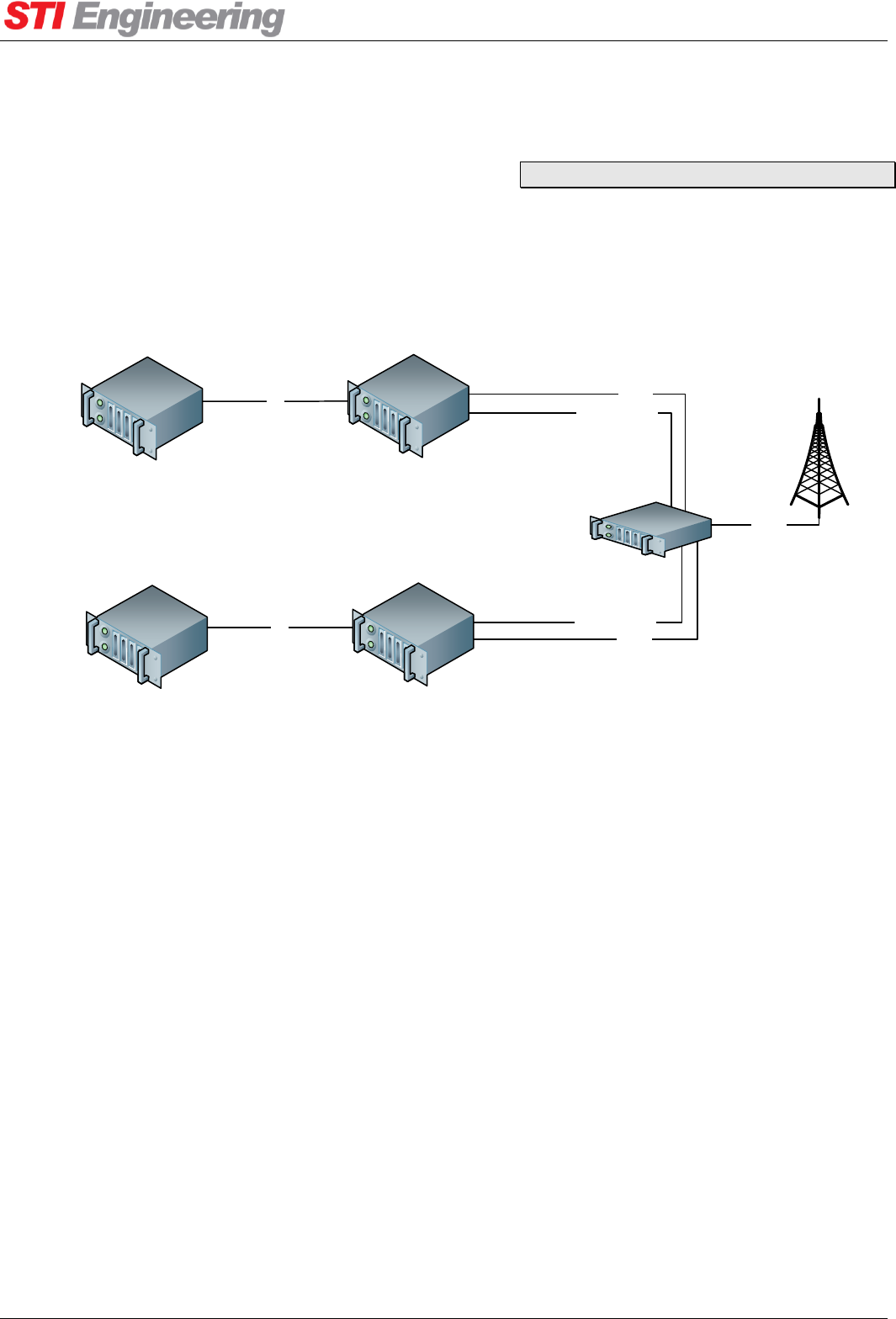
Appendix A Technical Specifications
RFI-148 & RFI-900 High Output Power Paging Transmitters User Manual Page 39 of 99
7. Hot Standby Operation
7.1 Overview
Hot standby operation allows the transmitter to operate in sites with high uptime requirements. It features
automatic fail-over to a secondary transmitter. Hot standby operation is an optional variant to the RFI-148
and RFI-900 that requires an additional external control unit (“RFI-PHSB”: Paging transmitting Hot-
Standby Box). The installation of such a system is illustrated in Figure 18.
RFI-148 250
(Primary)
RFI-148 250
(Secondary)
RFI-PHSB
Base Station Controller
(Secondary)
Base Station Controller
(Primary)
RF out
Expansion port
Expansion port
RF out
RF out
LIU
LIU
Figure 18: Hot standby system
The RFI-PHSB contains a high power RF switch to ensure minimal signal loss from the active RFI-148 250
to the antenna.
The pair of RFI-148 250 transmitters assume either a Primary or Secondary role. The role of the transmitter
is determined by which port it is connected to the RFI-PHSB, there are two ports “Primary” and
“Secondary”. The typical behaviour is that the Primary RFI-148 250 is keying up and sending paging data.
7.2 Configuration
The hot standby operation is configured with the Standby Mode setting:
Disabled (Default): The PTX is not operating in a hot standby environment and operates as normal
Hardware: The Can Go Active signal is presented on pin 17 of the LIU. Active High.
Software: The Can Go Active signal is controlled via Hayes AT command or Cruise Control.
Encoder Interface -> Hot Standby

Appendix A Technical Specifications
RFI-148 & RFI-900 High Output Power Paging Transmitters User Manual Page 40 of 99
Any changes to Standby Mode or installing the expansion port connector requires a power cycle to take
effect.
7.3 Operation
The Primary RFI-148 250 has control of the RF switch position. The default switch position, when no
Primary unit exists or the RFI-PHSB is unpowered, is for the Secondary unit. Upon power up the Primary
unit will always favour itself for the RF switch position, but the power up default is to leave the switch in the
Secondary unit position.
The Primary unit will change the RF switch to itself when all three signals satisfy the conditions:
“Can Go Active” is True
o For Hardware Standby Mode: Pin 17 is HIGH
o For Software Standby Mode: “Can Go Active (SW)” is set to “True” (Hayes command:
ATM12=1)”
“TX Fault” is False (See section 7.4 below)
“PTT” is Inactive
The Primary unit will change the RF switch to the Secondary unit if any two signals violate the conditions:
“Can Go Active” is True
“TX Fault” is False
Both the Primary and Second units know what position the switch is in. If the unit does not hold the switch
position, transmission is disabled using the “PTT Override” feature. In this case “PTT Override Status” will
read “DISABLED:In Standby”. Because of this behaviour, the Base Station Controllers providing encoded
paging data and PTT need not know of
the RF switch position.
7.4 Switchover Faults
An additional option per fault is provided that is the source of the “TX Fault” signal. By default, any faults
that would usually cause paging messages to fail to transmit will assert the “TX Fault” signal. This is
configurable per-fault within the Faults menu as the
“Go Standby” option.
7.5 Hardware Feedback
Two open-collector MOSFET outputs report a summary of the unit state:
IN STANDBY (LIU pin 23): Active when the unit is in Standby mode (ie, PTT disabled)
Faults -> Fault Configuration -> Go Standby
Encoder Interface -> External I/O

Appendix A Technical Specifications
RFI-148 & RFI-900 High Output Power Paging Transmitters User Manual Page 41 of 99
IS PRIMARY (LIU pin 24): Active if the unit is the Primary unit

Appendix A Technical Specifications
RFI-148 & RFI-900 High Output Power Paging Transmitters User Manual Page 42 of 99
Appendix A Technical Specifications
A.1 Type Approvals
RFI-148
Australia / New Zealand
AS NZS 4769.1
Australian Supplier ID: N161
FCC
CFR 47 Part 15 and Part 90
FCC ID P5MRFI148
ETSI
ETSI EN 300 113, EN 301
489, EN 60950
N/A
Table 7: RFI-148 type approvals
RFI-900
FCC
CFR 47 Part 15 and Part 90
FCC ID P5MRFI900
Table 8: RFI-900 type approvals
A.2 RFI-148/900250 Specifications
RF Operating Bandwidth
RFI-148
RFI-900
138 MHz – 174 MHz
929 MHz – 932 MHz
RF Switching Bandwidth
RFI-148
RFI-900
2.5 MHz
3MHz
RF Channel Spacing
12.5 kHz, 20 kHz, 25 kHz
RF Channel Occupation
POCSAG 512
POCSAG 1200
POCSAG 2400
FLEX-2 1600
FLEX-2 3200
FLEX-4 3200
FLEX-4 6400
6.25 kHz (wide) 3.18 kHz (narrow)
6.30 kHz (wide) 3.20 kHz (narrow)
7.45 kHz (wide) 3.78 kHz (narrow)
6.90 kHz (wide) 3.50 kHz (narrow)
7.30 kHz (wide) 3.70 kHz (narrow)
7.00 kHz (wide) 3.55 kHz (narrow)
7.80 kHz (wide) 3.95 kHz (narrow)
RF Frequency Raster
Selectable: 30kHz, 25 kHz, 20 kHz, 15kHz, 12.5 kHz, 10 kHz,
7.5kHz, 6.25 kHz, 5 kHz, 2.5kHz.
RF Output
20 to 250 Watts +/- 0.5 dB
RF Diag
Transmitting mode power level: -50 dBm
Listening mode insertion loss: 12 dB +/- 2 dB
Internal Reference
Frequency: 10 MHz
Stability: +/- 1 ppm (-30 to +75 degrees C)
External Reference
Frequency: 5 or 10 MHz
Amplitude: -20 to 15 dBm

Appendix A Technical Specifications
RFI-148 & RFI-900 High Output Power Paging Transmitters User Manual Page 43 of 99
Modulation
POCSAG 512, 1200, 2400 bps (2-level FSK).
FLEX 1600 (2-level FSK), 3200 (2- or 4-level FSK), 6400
bps (4-level FSK).
Real-time Clock
Time drift: 1 hour after 10 years
Battery life: 43 years (estimated)
Ethernet Port
10BASE-T/100BASE-TX, auto-negotiating.
Serial Ports
Dual asynchronous full-duplex RS-232
Baud rates (rear port only): 300, 600, 1200, 2400, 4800, 9600,
19200, 38400, 57600, 115200 bps
Data bits (rear port only): 7 or 8
Parity (rear port only): None, odd, or even
Stop bits (rear port only): 1 or 2
Flow control (rear port only): None or hardware (RTS/CTS)
Control lines (rear port only): RTS, CTS, DTR, DCD
Front port configuration locked to 19200 8N1
Front port: DCE
Rear Port
RFI-148
RFI-900
DTE
DCE
Digital Inputs
TTL Schmitt trigger with internal 100 KΩ pull-up.
Frequency Select 1
Frequency Select 2
Frequency Select 3
Frequency Select 4
Protocol Select
Hardware PTT
Tx Data L-bit
Tx Data H-bit
Transmit Clock
Aux Input 1 (General purpose, RFI-148 only)
Alarm Outputs
Open-collector Darlington with 500 mA sink current.
Input Voltage (Model
specific)
24VDC Model: 20 V to 31.2 V for 24 V nominal
-48VDC Model: -40.5 V to -57 V for -48 V nominal
110/240V AC Model: 100 to 250 V AC, 50 to 60 Hz
Operating Temperature 24
V DC and -48 V DC
-30 to 55 0C
Operating Temperature
110/240VAC
-30 to 50 0C
Connectors (DC model)
DC Power: Terminal block Phoenix Contact 1703454 and cable
mount plug Phoenix Contact 1967456.
Front Serial Port: DE-9 RS-232 Female (DCE)
LIU Interface: DC-37 Female
Ethernet: RJ45 socket

Appendix A Technical Specifications
RFI-148 & RFI-900 High Output Power Paging Transmitters User Manual Page 44 of 99
RF Output: N-type female 50 Ω
RF Diag: TNC female 50 Ω
External Reference Input: BNC female
Rear Serial Port
RFI-900
RFI-148
DE-9 RS-232
Female (DCE)
DE-9 RS-232
Male (DTE)
DC Output (RFI-900 only)
Voltage
24V
Max. Load
2A
Table 9: RFI-148/900250 Specifications
RFI-148 current draw
Typical Current Draw at
24 V DC.
AMCA, FCC
ETSI
Idle: 0.6 A
20 W: 5.85 A
100 W: 11.58 A
250 W: 17.28 A
Idle: 0.6 A
20 W: 6.03 A
100 W: 11.79 A
250 W: 19.05 A
Typical Current Draw at -
48 V DC.
AMCA, FCC
ETSI
Idle: 0.5 A
20 W: 3.42 A
100 W: 6.51 A
250 W: 10.31 A
Idle: 0.5 A
20 W: 3.52 A
100 W: 6.89 A
250 W: 11.48 A
Typical Current Draw at
240 V AC
ACMA, FCC
ETSI
Idle: 0.10 A
20 W: 0.79 A
100 W: 1.43 A
250 W: 2.14 A
Idle: 0.10 A
20 W: 0.82 A
100 W: 1.46 A
250 W: 2.36 A
Table 10: RFI-148 current draw
RFI-900 current draw
Typical Current Draw at
120 V AC
Figures quoted are with fans on unless specified.
Idle (Fans off): 0.48 A
20 W: 2.01 A
50 W: 2.84 A
100 W: 3.93 A
200 W: 5.56 A
250 W: 6.22 A
Table 11: RFI-900 current draw
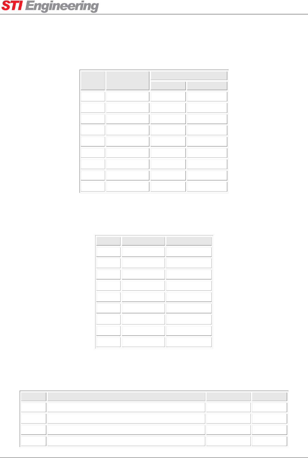
Appendix A Technical Specifications
RFI-148 & RFI-900 High Output Power Paging Transmitters User Manual Page 45 of 99
A.3 Serial Connectors
A.3.1 Rear Serial Port
Pin
Function
Direction
RFI-148
RFI-900
1
DCD
Input
Output
2
RxD
Input
Output
3
TxD
Output
Input
4
DTR
Output
Input
5
GND
6
N/A
7
RTS
Output
Input
8
CTS
Input
Output
9
N/A
Table 12: Back Panel Connector Pin OutRFI-900
A.3.2 Front Serial Port (DCE)
Pin
Function
Direction
1
N/A
2
RxD
Output
3
TxD
Input
4
N/A
5
GND
6
N/A
7
N/A
8
N/A
9
N/A
Table 13: Front Connector Pin Out
A.4 LIU Interface
Pin
Function
Label
Direction
1
Protocol Select
PRO
Input
2
Alarm 3
ALM3
Output
3
Alarm 10
ALM10
Output
4
Alarm 11
ALM11
Output
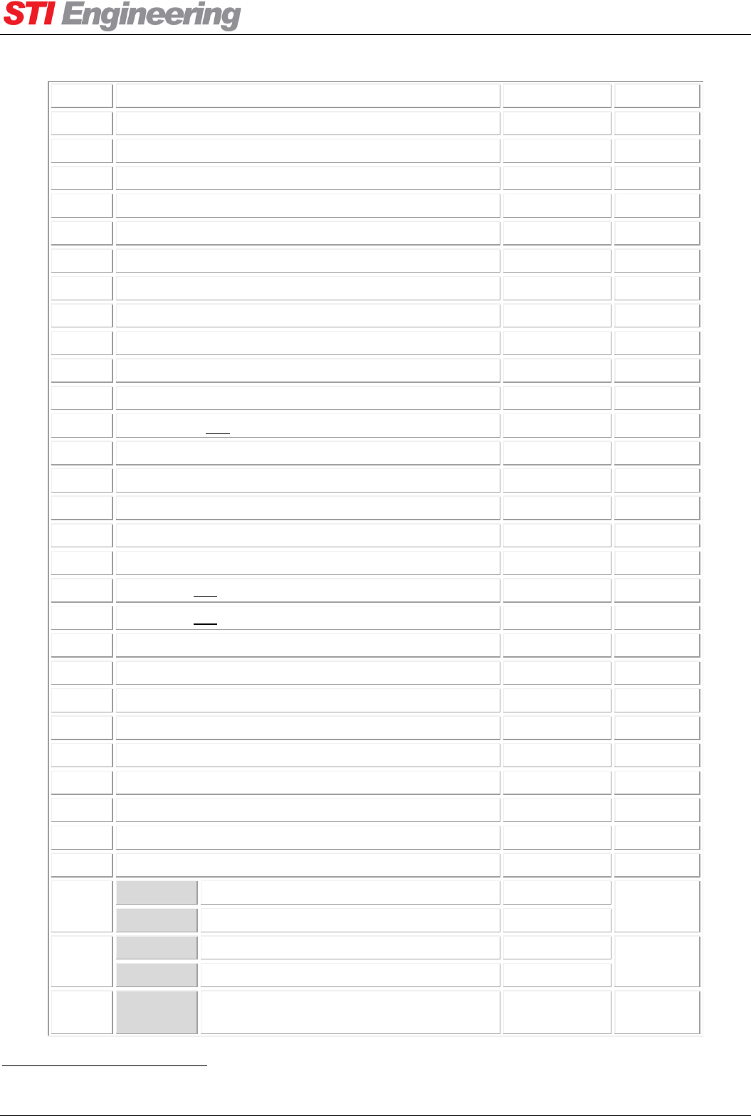
Appendix A Technical Specifications
RFI-148 & RFI-900 High Output Power Paging Transmitters User Manual Page 46 of 99
5
Frequency Select 4
CH4
Input
6
Frequency Select 3
CH3
Input
7
Frequency Select 2
CH2
Input
8
Frequency Select 1
CH1
Input
9
GND
GND
10
GND
GND
11
Hardware PTT
PTT
Input
12
Combined Alarm
COMB
Output
132
Auxiliary Input 1
Aux Input 1
Input
14
Alarm 1
ALM1
Output
15
Tx Data L-bit
LB
Input
16
Tx Data H-bit
HB
Input
17
LIU Detect OR Hot Standby “Can Go Active”
DET
Input
18
Tx Data Clock
CLK
Input
19
GND
GND
20
Alarm 2
ALM2
Output
21
Alarm 7
ALM7
Output
22
Alarm 4
ALM4
Output
23
Alarm 12 OR Hot Standby “IN STANDBY”
ALM12
Output
24
Alarm 13 OR Hot Standby “IS PRIMARY”
ALM13
Output
25
N/A
26
Alarm 9
ALM9
Output
27
N/A
28
N/A
29
Alarm 5
ALM5
Output
30
Alarm 6
ALM6
Output
31
Alarm 8
ALM8
Output
32
+5 V
5V
Output
33
+5 V
5V
Output
34
RFI-148
+12 V
12V
Output
RFI-900
+24V
24V
35
RFI-148
+12 V
12V
Output
RFI-900
+24V
24V
36
RFI-148
+24 V nominal (Note: identical to DC
input voltage for 24 VDC model)
24V
Output
2
A general purpose input available on the RFI-148 only.
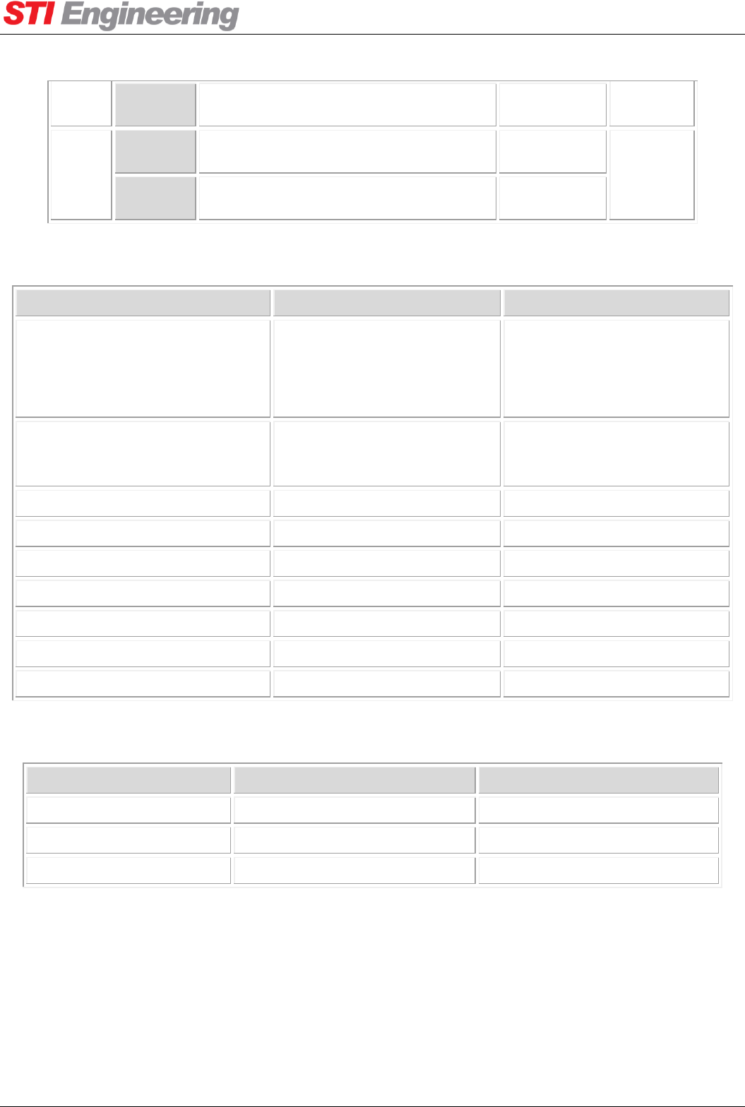
Appendix A Technical Specifications
RFI-148 & RFI-900 High Output Power Paging Transmitters User Manual Page 47 of 99
RFI-900
+48 V nominal (Note: identical to DC
input voltage)
48V
37
RFI-148
+24 V nominal (Note: identical to DC
input voltage for 24 VDC model)
24V
Output
RFI-900
+48 V nominal (Note: identical to DC
input voltage)
48V
Table 14: LIU Interface Pin Out
Non-exciter-based build
Exciter-based build
Interface standards
5 V CMOS
5 V TTL (with modification)
3.3 TTL (with modification)
3.3 CMOS (with modification)
5 V CMOS
5 V TTL
3.3 TTL
3.3 CMOS
Input resistance
Schmitt trigger with internal
33 KΩ pull-up.
Schmitt trigger with internal
100 KΩ pull-up (148P306-B),
33 KΩ pull-up (148P306-C).
Nominal logic high input voltage
3.3 V to 5 V
3.3 V to 5 V
Minimum logic high input voltage
3.5 V
2.5 V
Maximum logic high input voltage
12 V
12 V
Nominal logic low input voltage
0 V
0 V
Maximum logic low input voltage
1.5 V
0.5 V
Minimum logic low input voltage
-12 V
-12 V
Over voltage protection
±12 V
±12 V
Table 15: LIU Encoder Input Specifications
Non-exciter-based build
Exciter-based build
Output transistor type
Open collector MOSFET
Open collector Darlington
Maximum sink current
500 mA
50 mA
Maximum output voltage
50 V
12 V
Table 16: LIU Alarm Output Specifications
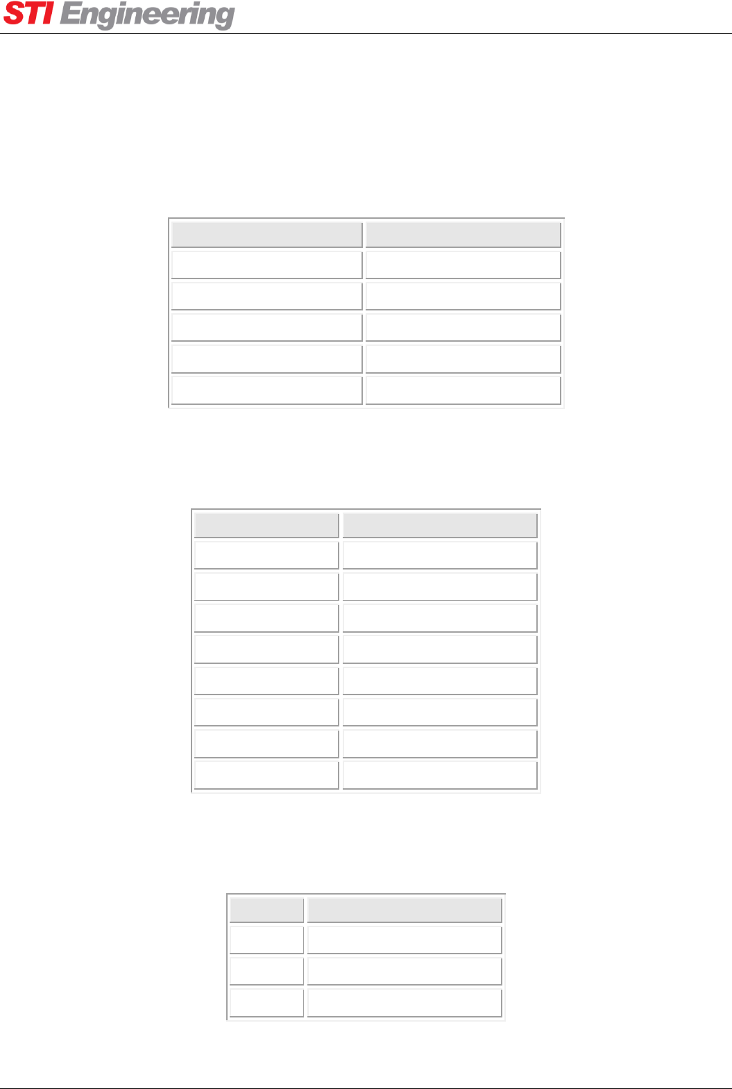
Appendix B Controller Configurations
RFI-148 & RFI-900 High Output Power Paging Transmitters User Manual Page 48 of 99
Appendix B Controller Configurations
The following section provides example wiring between the transmitter and some common controllers.
B.1 Motorola NIU Controller / FLEX Mode
External NIU(TB3, TB4)
Transmitter (LIU, DC37)
TB3-2: Tx Clock
DC37-18: CLK
TB3-4: Tx key
DC37-11: PTT
TB3-8: GND
DC37-19: GND
TB4-2: Rx FQ1
DC37-15: LB
TB4-3: Rx FQ2
DC37-16: HB
Table 17: Motorola NIU Controller / FLEX Mode Connection
B.2 Glenayre C2000 Controller / FLEX Mode
C2000 (J4)
Transmitter (LIU, DC37)
J4-10: GND
DC37-19: GND
J4-26: TXKEY+
DC37-11: PTT
J4-3: TD0+, MSB
DC37-16: HB
J4-34: TD1+, LSB
DC37-15: LB
J4-18: Data Clock+
DC37-18: CLK
J4-7: Freq2
DC37-6: CH3
J4-6: Freq1
DC37-7: CH2
J4-36: Freq0
DC37-8: CH1
Table 18: Glenayre C2000 Controller / FLEX Mode Connection
B.3 Glenayre C2000 Controller / POCSAG Mode
Encoder
Transmitter (LIU, DC37)
Tx Data
DC37-15: LB
PTT
DC37-11: PTT
GND
DC37-19: GND
Table 19: Glenayre C2000 Controller / POCSAG Mode Connection

Appendix B Controller Configurations
RFI-148 & RFI-900 High Output Power Paging Transmitters User Manual Page 49 of 99
B.4 Zetron Model 66 Transmitter Controller / POCSAG Mode
Model 66
Transmitter (DC37)
DIG DATA (pin 10)
DC37-15: LB
DIG PTT (pin 7)
DC37-11: PTT
GND (pin 3)
DC37-19: GND
Table 20: Zetron Model 66 Controller / POCSAG Mode Connection
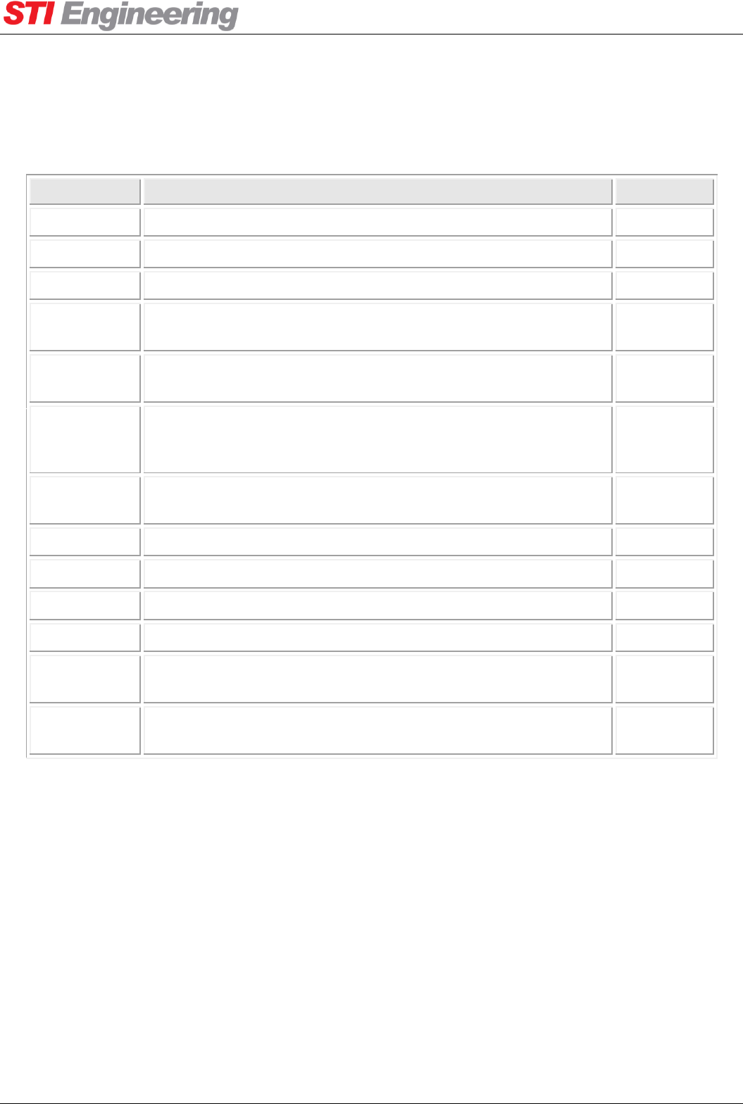
Appendix C Management Reference
RFI-148 & RFI-900 High Output Power Paging Transmitters User Manual Page 50 of 99
Appendix C Management Reference
C.1 Serial Port Diagnostics
Name
Description
AT
Rx Total
The size of the input buffer.
I20[p,0]
Rx Used
The number of bytes currently stored in the input buffer.
I20[p,1]
Rx Bytes
The total number of bytes received.
I20[p,2]
Rx Errors
The total number of receive errors that have occurred. Sum of Rx
Overflows, Rx Overruns, Rx Framing, and Rx Parity errors.
I20[p,3]
Rx Overflows
The number of receive overflow errors that have occurred. An
overflow occurs when data is received, but the buffer is full.
I20[p,4]
Rx Overruns
The number of overrun errors that have occurred. An overrun
occurs when the device is overloaded and cannot handle the
incoming data.
I20[p,5]
Rx Framing
The number of framing errors that have occurred. Framing errors
usually occur due to mismatched serial port baud rates.
I20[p,6]
Rx Parity
The number of serial parity errors that have been detected.
I20[p,7]
Tx Total
The size of the output buffer.
I20[p,8]
Tx Used
The number of bytes currently stored in the output buffer.
I20[p,9]
Tx Bytes
The total number of bytes that have been transmitted.
I20[p,10]
Tx Errors
The total number of errors that have occurred while transmitting.
This is equal to the Tx Overflows count.
I20[p,11]
Tx Overflows
The number of transmit overflow errors that have occurred. This
occurs when there is data to transmit, but the buffer is full.
I20[p,12]
Table 21: Serial Port Statistics

Appendix C Management Reference
RFI-148 & RFI-900 High Output Power Paging Transmitters User Manual Page 51 of 99
C.2 SNMP Diagnostic Parameters
Table 22 outlines the parameters accessible by SNMP. An ‘R’ under the access column indicates the
parameter is read-only; an ‘R/W’ indicates read-write.
SNMP Textual Name
Access
Description
Diagnostics
rfiDiagTimeLcl
R
The current local time (in seconds since Jan 1 1970).
rfiDiagTimeLclstring
R
The current local time.
rfiDiagTimeUp
R
Seconds since the radio powered up.
rfiDiagTimeUtc
R/W
The current UTC (in seconds since Jan 1 1970).
Fan Control
rfiFanCtrlForce
R/W
Manual fan override (allows fans to be forced on).
rfiFanCtrlSensor
R/W
Temperature sensor used for fan control.
rfiFanCtrlTempOff
R/W
Sensed temperature below which fans will be turned off.
rfiFanCtrlTempOn
R/W
Sensed temperature above which fans will be turned on.
rfiFanSensTemp
R
Current temperature at sensor used for fan control.
Faults
rfiFaultHistTblFault
R
The fault that occurred.
rfiFaultHistTblTime
R
The time that the fault occurred.
rfiFaultTblAction
R/W
Configured action to be taken when this fault occurs.
rfiFaultTblActtime
R
Duration for which this fault has been active, or 0 if the fault is
not active.
rfiFaultTblCount
R/W
The number of times this fault has occurred since the statistics
were reset.
rfiFaultTblLatch
R/W
Configured latching mechanism for this fault.
rfiFaultTblName
R
Name of the fault in this row of the table.
rfiFaultTblStatus
R
Indicates whether or not this fault condition is currently active.
Identity
rfiIdApproval
R
International type approval code which applies to this device.
rfiIdFwver
R
Version information for the firmware loaded in this device.
rfiIdMfdate
R
Date on which this device was manufactured.
rfiIdOphours
R
An approximation of the total number of hours that this device
has been powered up.
rfiIdProdstr
R
The model name for this device.
rfiIdSerialno
R
Factory assigned serial number for this device.
Paging Protocols
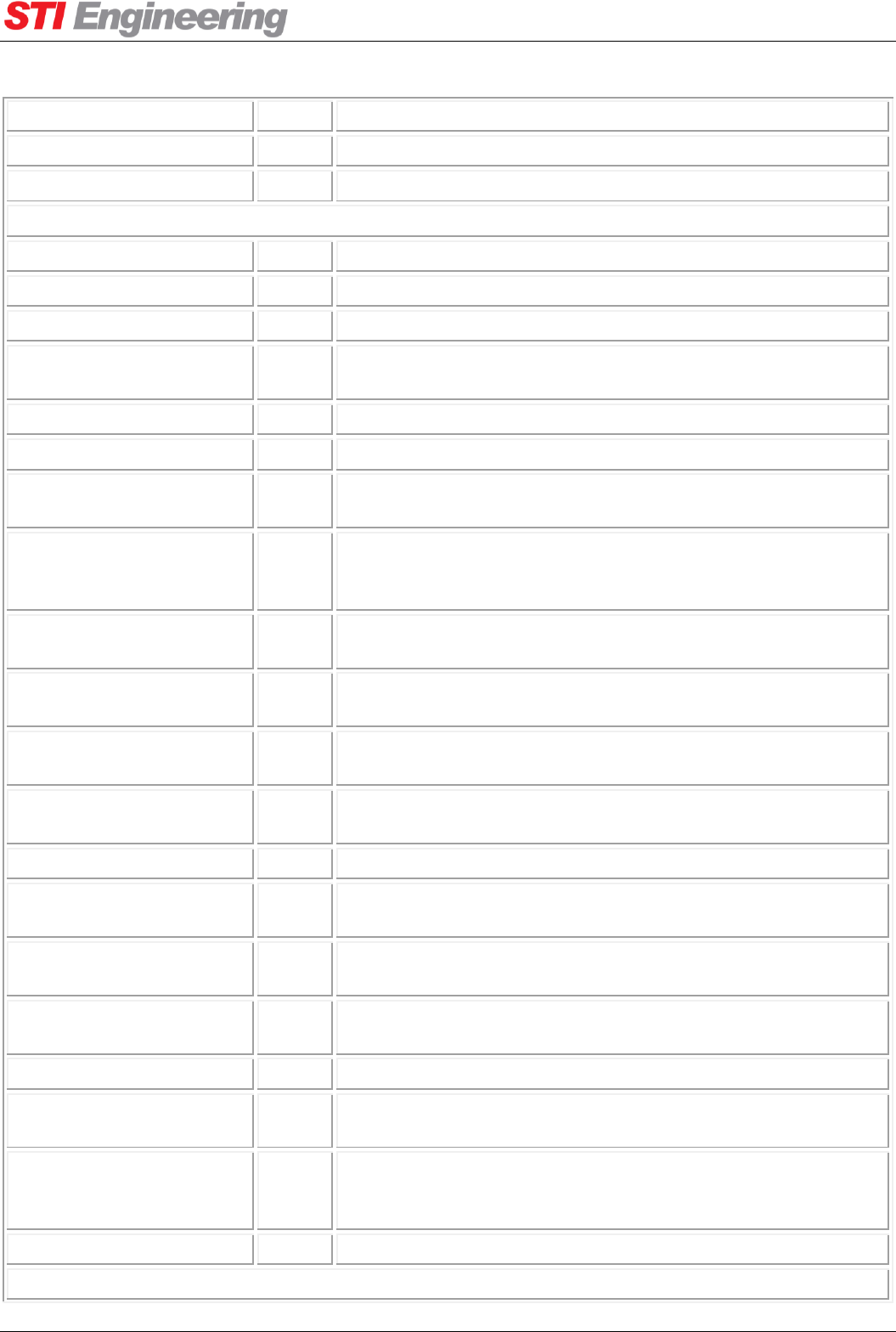
Appendix C Management Reference
RFI-148 & RFI-900 High Output Power Paging Transmitters User Manual Page 52 of 99
rfiPageProtSelect
R/W
Active protocol profile.
rfiPageProtTblOffset
R/W
Configured carrier frequency offset for this profile.
rfiPageProtTblProt
R/W
Configured paging protocol for this profile.
Radio Parameters
rfiRadioFrqChSelect
R/W
Currently selected radio channel number.
rfiRadioFrqChTblNo
R
Radio channel number.
rfiRadioFrqChTblTxfrq
R/W
Radio channel transmit frequency.
rfiRadioFrqRefCur
R
The current reference being used to generate channel
frequencies.
rfiRadioFrqRefExt
R
The state of the external reference.
rfiRadioFrqRefMode
R/W
The reference selection method.
rfiRadioIsolatorFeed
R
Hardware feedback from the isolator attentuation switchout
mechanism.
rfiRadioIsolatorMode
R/W
Sets the isolator for normal transmission (high attenuation on RF
diag port) or for listening to signal from antenna, for network
testing (low attenuation on RF diag port, transmission disabled).
rfiRadioTxDelay
R/W
Applies an artificial transmission delay to all data. Can be used
for matching delay in heterogeneous transmitter networks.
rfiRadioTxIdletime
R
Time since last transmission ended (if not transmitting), or zero
if currently transmitting.
rfiRadioTxOntime
R
Time since current transmission started (if transmitting), or zero
if not currently transmitting.
rfiRadioTxPttAuto
R/W
Setting to enable or disable the automatic Push-To-Talk on data
feature.
rfiRadioTxPttAutoTmout
R/W
No-data timeout for the automatic PTT feature.
rfiRadioTxPttOverride
R/W
Master override allowing transmission to be completely disabled,
regardless of PTT inputs.
rfiRadioTxPttStatus
R
If PTT is currently disabled, describes what is the source of the
override.
rfiRadioTxPttTofftime
R/W
Delay before turning off the transmitter after PTT off is
signalled.
rfiRadioTxPwrCtrlLvl
R/W
Transmitter output power setting.
rfiRadioTxStatus
R
Current transmission status. May be off, on, or waiting for PTT
delay to expire before turning off.
rfiRadioTxTimeout
R/W
Continuous transmission time, in seconds, which will cause a
Transmit Timeout fault to occur. By default this will disable
further transmission until the fault is cleared.
rfiRadioTxTimeouten
R/W
Enable or disable the transmit timeout feature.
Sensors

Appendix C Management Reference
RFI-148 & RFI-900 High Output Power Paging Transmitters User Manual Page 53 of 99
rfiSensTblCutoffHi
R/W
Upper cutoff value for this sensor. Measurements which exceed
this cutoff cause a fault.
rfiSensTblCutoffLo
R/W
Lower cutoff value for this sensor. Measurements lower than this
cutoff cause a fault.
rfiSensTblFault
R
Current fault status associated with this sensor.
rfiSensTblMax
R
Maximum recorded sensor value since the statistics were reset.
rfiSensTblMin
R
Minimum recorded sensor value since the statistics were reset.
rfiSensTblName
R
Name of the fault in this row of the table.
rfiSensTblVal
R
Current measured sensor value.
Table 22: SNMP Diagnostic Parameters

Appendix D Hayes AT Reference
RFI-148 & RFI-900 High Output Power Paging Transmitters User Manual Page 54 of 99
Appendix D Hayes AT Reference
AT-only commands
Print All Sensors
Legacy command for printing all sensor values as a comma separated list.
ATI100: Runs the Print All Sensors routine
Print Faults Mask
Prints a comma separated list of active faults, each fault represented by their index. Prints 'None.' if there are
no faults active.
ATI101: Runs the Print Faults Mask routine
Print Upper Limits
Legacy command for printing all sensor upper cutoff values as a comma separated list.
ATI102: Runs the Print Upper Limits routine
Print Lower Limits
Legacy command for printing all sensor lower cutoff values as a comma separated list.
ATI103: Runs the Print Lower Limits routine
Print Sensor Minimums
Legacy command for printing all sensor minimum recorded values since last sensor history reset as a comma
separated list.
ATI105: Runs the Print Sensor Minimums routine
Print Sensor Maximums
Legacy command for printing all sensor maximum recorded values since last sensor history reset as a
comma separated list.
ATI106: Runs the Print Sensor Maximums routine
Read Faults Detailed
Print all active faults, in the format "<FaultNumber>:<ActiveDuration>:<Counter>, ..."
ATI180: Runs the Read Faults Detailed routine
Online
(Alias for ATO) Exit command parsing mode and go online
ATO0: Runs the Online routine.
Online
Exit command parsing mode and go online
ATO: Runs the Online routine.
Reset
Perform a software reset
AT&T9: Runs the Reset routine.
RUF Init
Initialise the length for a .ruf file transfer
ATU1=n: Runs the RUF Init routine where n is the length of the .ruf file in bytes.
RUF Block

Appendix D Hayes AT Reference
RFI-148 & RFI-900 High Output Power Paging Transmitters User Manual Page 55 of 99
Send a data block as part of a .ruf file transfer, the CRC over the data is returned
ATU2=n: Runs the RUF Block routine where n is the .ruf file data block.
RUF Status
Query the status of an in-progress .ruf file transfer
ATU4: Runs the RUF Status routine.
RUF Query
Query the most recently completed .ruf file transfer
ATU5: Runs the RUF Query routine.
RUF Update
Execute an update to the most recently transferred .ruf file
ATU6: Runs the RUF Update routine.
Save All
Write through all AT command sets since power-on-reset to EEPROM
AT&W: Runs the Save All routine.
Password
Set the device password
AT%23=n: Runs the Password routine where n is the new password.
Open Menu
Open the terminal menu on this stream
AT?: Runs the Open Menu routine.
Stream Index
Show the index number of this stream
AT&S0: Runs the Stream Index routine.
Cruise Control Menu
Product String
The model name for this device.
ATI0: Returns the current value of Product String.
Manufacture Date
Date on which this device was manufactured.
ATI5: Returns the current value of Manufacture Date.
Serial Number
Factory assigned serial number for this device.
ATI6: Returns the current value of Serial Number.
Radio Menu
Current Transmit Time
Time since current transmission started (if transmitting), or zero if not currently transmitting.
ATP119: Returns the current value of Current Transmit Time.
Transmitter Idle Time
Time since last transmission ended (if not transmitting), or zero if currently transmitting.
ATP116: Returns the current value of Transmitter Idle Time.

Appendix D Hayes AT Reference
RFI-148 & RFI-900 High Output Power Paging Transmitters User Manual Page 56 of 99
PTT Override Status
If PTT is currently disabled, describes what is the source of the override.
ATP6: Returns the current value of PTT Override Status.
PTT Override
Master override allowing transmission to be completely disabled, regardless of PTT inputs.
ATP7: Returns the current value of PTT Override.
ATP7=n sets PTT Override to n
Values accepted:
0 = Enable Transmit
1 = Disable Transmit
PTT Turn Off Delay
Delay before turning off the transmitter after PTT off is signalled.
ATP112: Returns the current value of PTT Turn Off Delay.
ATP112=n[.m]: Sets the value of PTT Turn Off Delay to n s, given that 0.000 <= n <= 65.535.
Enable Transmit Timeout
Enable or disable the transmit timeout feature.
ATP117: Returns the current value of Enable Transmit Timeout.
ATP117=n sets Enable Transmit Timeout to n
Values accepted:
0 = False
1 = True
Transmit Timeout
Continuous transmission time, in seconds, which will cause a Transmit Timeout fault to occur. By default
this will disable further transmission until the fault is cleared.
ATP118: Returns the current value of Transmit Timeout.
ATP118=n[.m]: Sets the value of Transmit Timeout to n s, given that 0.000 <= n <= 4294967.295.
Absolute Delay Adjustment
Applies an artificial transmission delay to all data. Can be used for matching delay in heterogeneous
transmitter networks.
ATI154: Returns the current value of Absolute Delay Adjustment.
ATI154=n[.m]: Sets the value of Absolute Delay Adjustment to n ms, given that 0.000 <= n <= 40.000.
Power Menu
Transmitter Status
Current transmission status. May be off, on, or waiting for PTT delay to expire before turning off.
ATP115: Returns the current value of Transmitter Status.
(Distributer) Max Tx Power
Override the maximum configurable transmit power to a sublevel of the radios capabilities.
ATS209: Returns the current value of Max Tx Power.
ATS209=n: Sets the value of Max Tx Power to n W, given that 20 <= n <= 250.
Tx Power

Appendix D Hayes AT Reference
RFI-148 & RFI-900 High Output Power Paging Transmitters User Manual Page 57 of 99
Transmitter output power setting.
ATS45: Returns the current value of Tx Power.
ATS45=n: Sets the value of Tx Power to n W, given that 20 <= n <= 250.
Power Foldback
The percent of transmit power in Watts to foldback to when the scale transmit power fault action goes active.
ATP120: Returns the current value of Power Foldback.
ATP120=n: Sets the value of Power Foldback to n %%, given that 0 <= n <= 100.
Transmit On
Software PTT method to key up the transmitter.
ATP3: Runs the Transmit On routine.
Transmit Off
Software PTT method to key down the transmitter.
ATP2: Runs the Transmit Off routine.
Channel Menu
Tx Range
ATS183: Returns the current value of Tx Range.
Current Tx Freq
ATS184: Returns the current value of Current Tx Freq.
Raster
Read-only node for viewing the raster frequency of the radio.
ATS185: Returns the current value of Raster.
Channel Width
Read-only node for viewing the channel width of the radio.
ATS186: Returns the current value of Channel Width.
Current Channel
Currently selected radio channel number.
ATS54: Returns the current value of Current Channel.
ATS54=n: Sets the value of Current Channel to n , given that 1 <= n <= 17.
(Distributer) Channel Count
Number of channels that can be switched between using the current channel setting.
ATS210: Returns the current value of Channel Count.
ATS210=n: Sets the value of Channel Count to n , given that 1 <= n <= 16.
Advanced Menu
(Distributer) Tx Base Freq
Minimum transmit frequency.
ATS211: Returns the current value of Tx Base Freq.
ATS211=n[.m]: Sets the value of Tx Base Freq to n MHz, given that 130.000000 <= n <= 1050.000000.
(Distributer) Bandwidth

Appendix D Hayes AT Reference
RFI-148 & RFI-900 High Output Power Paging Transmitters User Manual Page 58 of 99
The amount of usable frequncies available to the radio.
ATS212: Returns the current value of Bandwidth.
ATS212=n[.m]: Sets the value of Bandwidth to n MHz, given that 1.000000 <= n <= 100.000000.
(Distributer) Raster
Frequency raster. All channel frequencies must be divisible by the raster.
ATS57: Returns the current value of Raster.
ATS57=n sets Raster to n
Values accepted:
0 = 0.001 kHz
1 = 2.500 kHz
2 = 5.000 kHz
3 = 6.250 kHz
4 = 7.500 kHz
5 = 10.000 kHz
6 = 12.500 kHz
7 = 15.000 kHz
8 = 20.000 kHz
9 = 25.000 kHz
10 = 30.000 kHz
Channel Width
The radios channel width.
ATS66: Returns the current value of Channel Width.
ATS66=n sets Channel Width to n
Values accepted:
0 = 12.500 KHz
1 = 25.000 KHz
Channel Table
Tx Freq
Radio channel transmit frequency.
ATS55[a]: Returns the current value of Tx Freq.
ATS55[a]=n[.m]: Sets the value of Tx Freq to n MHz, given that 130.000000 <= n <= 1050.000000. Where:
a = Channel Table table index (starting from 1)
Reference Menu
Current Reference
The current reference being used to generate channel frequencies.
ATI122: Returns the current value of Current Reference.
External Reference
The state of the external reference.
ATI123: Returns the current value of External Reference.
Reference Mode
The reference selection method.
ATI120: Returns the current value of Reference Mode.
ATI120=n sets Reference Mode to n
Values accepted:

Appendix D Hayes AT Reference
RFI-148 & RFI-900 High Output Power Paging Transmitters User Manual Page 59 of 99
0 = Internal
1 = External With Failover
Ext. Ref. Frequency
Configures the frequency of the external reference.
ATI121: Returns the current value of Ext. Ref. Frequency.
ATI121=n sets Ext. Ref. Frequency to n
Values accepted:
0 = 5 MHz
1 = 10 MHz
Isolator Menu
Feedback
Hardware feedback from the isolator attentuation switchout mechanism.
ATP33: Returns the current value of Feedback.
Isolator Mode
Sets the isolator for normal transmission (high attenuation on RF diag port) or for listening to signal from
antenna, for network testing (low attenuation on RF diag port, transmission disabled).
ATP31: Returns the current value of Isolator Mode.
ATP31=n sets Isolator Mode to n
Values accepted:
0 = Set for Transmitting
1 = Set for Listening
Listening Mode Timeout
A timeout in seconds that starts when the isolator is set to listening mode. When the timeout expires the
isolator will automatically return to transmitting mode.
ATP35: Returns the current value of Listening Mode Timeout.
ATP35=n[.m]: Sets the value of Listening Mode Timeout to n s, given that 0.000 <= n <= 65.535.
Enable Listening Timeout
Enables or disables listening mode timeout.
ATP34: Returns the current value of Enable Listening Timeout.
ATP34=n sets Enable Listening Timeout to n
Values accepted:
0 = Disabled
1 = Enabled
Paging Protocols Menu
POCSAG Deviation
ATP105: Returns the current value of POCSAG Deviation.
FLEX Deviation
ATP106: Returns the current value of FLEX Deviation.
Encoding Mode
Configure the encoding source for paging transmitter data.
ATN10: Returns the current value of Encoding Mode.
ATN10=n sets Encoding Mode to n
Values accepted:

Appendix D Hayes AT Reference
RFI-148 & RFI-900 High Output Power Paging Transmitters User Manual Page 60 of 99
0 = External Encoder
1 = TNPP Serial
2 = TNPP TCP:64250
3 = TNPP UDP:64250
4 = PET/TAP Serial
5 = PET/TAP TCP:64250
6 = PET/TAP UDP:64250
PET/TAP Menu
Current State
ATN43: Returns the current value of Current State.
Line Separator
The line separator output between new lines. Configurable for compatibility across terminals.
ATN15: Returns the current value of Line Separator.
ATN15=n sets Line Separator to n
Values accepted:
0 =
1 =
Timeout
Intercharacter timeout before purging input buffer and reverting to idle state.
ATN16: Returns the current value of Timeout.
ATN16=n[.m]: Sets the value of Timeout to n s, given that 0.5 <= n <= 10.0.
Baud Rate
Baud rate at which encoded POSCAG pages are sent over the air.
ATN19: Returns the current value of Baud Rate.
ATN19=n sets Baud Rate to n
Values accepted:
0 = 512
1 = 1200
2 = 2400
Stay Logged In
Remains logged in indefinitely after receiving a valid login string.
ATN41: Returns the current value of Stay Logged In.
ATN41=n sets Stay Logged In to n
Values accepted:
0 = False
1 = True
Implied Login
Option to skip login sequence if a <STX> is read while waiting for wake up sequence.
ATN42: Returns the current value of Implied Login.
ATN42=n sets Implied Login to n
Values accepted:
0 = Disabled
1 = PG1
2 = PG3

Appendix D Hayes AT Reference
RFI-148 & RFI-900 High Output Power Paging Transmitters User Manual Page 61 of 99
Detect Numeric Pages
When enabled, will encode a POCSAG page in numeric format (rather than alpha-numeric) if the message is
wholly formed by digits.
ATN14: Returns the current value of Detect Numeric Pages.
ATN14=n sets Detect Numeric Pages to n
Values accepted:
0 = False
1 = True
Group Code
Allows the use of the final character or digit in the Pager ID field of a message submission to determine the
function bits of the paging message.
ATN13: Returns the current value of Group Code.
ATN13=n sets Group Code to n
Values accepted:
0 = None
1 = Trailing Character
2 = Trailing Digit
Reset Statistics
Reset the TAP/PET statistics accumulated since start-up.
ATN17: Runs the Reset Statistics routine.
Statistics Table
Name
Value
ATN18[a]: Returns the current value of Value.
Where: a = Statistics table index (starting from 0)
TNPP Menu
Address
The address of this TNPP node.
ATN23: Returns the current value of Address.
ATN23=n: Sets the value of Address to n , given that 0 <= n <= 65535.
Promiscuous Mode
When enabled, this node will accept packets destined for any address.
ATN24: Returns the current value of Promiscuous Mode.
ATN24=n sets Promiscuous Mode to n
Values accepted:
0 = False
1 = True
Transparent CRC support
ATN25: Returns the current value of Transparent CRC support.
ATN25=n sets Transparent CRC support to n
Values accepted:
0 = False
1 = True

Appendix D Hayes AT Reference
RFI-148 & RFI-900 High Output Power Paging Transmitters User Manual Page 62 of 99
Address Extension support
ATN26: Returns the current value of Address Extension support.
ATN26=n sets Address Extension support to n
Values accepted:
0 = False
1 = True
Multi-Block support
ATN27: Returns the current value of Multi-Block support.
ATN27=n sets Multi-Block support to n
Values accepted:
0 = False
1 = True
Large Packet support
ATN28: Returns the current value of Large Packet support.
ATN28=n sets Large Packet support to n
Values accepted:
0 = False
1 = True
Reset TNPP Statistics
ATN22: Runs the Reset TNPP Statistics routine.
TNPP Statistics Table
Name
ATN20[a]: Returns the current value of Name .
Where: a = TNPP Statistics table index (starting from 0)
Count
ATN21[a]: Returns the current value of Count.
Where: a = TNPP Statistics table index (starting from 0)
POCSAG Menu
Preamble Length
Length of the preamble sent prior to paging data.
ATN30: Returns the current value of Preamble Length.
ATN30=n: Sets the value of Preamble Length to n bit, given that 32 <= n <= 2304.
Function Override
Override the function bits in the address codeword. Default (`Message Encoding`) is to set the function bits
based on message encoding: Numeric: 00, Tone: 01, Alpha-numeric: 11.
ATN11: Returns the current value of Function Override.
ATN11=n sets Function Override to n
Values accepted:
0 = Message Encoding
1 = Always 00
2 = Always 01
3 = Always 10
4 = Always 11

Appendix D Hayes AT Reference
RFI-148 & RFI-900 High Output Power Paging Transmitters User Manual Page 63 of 99
Purge Timeout
Duration to wait to collate paging messages for sending over the air.
ATN29: Returns the current value of Purge Timeout.
ATN29=n: Sets the value of Purge Timeout to n ms, given that 250 <= n <= 5000.
Reset Statistics
ATN40: Runs the Reset Statistics routine.
Page Repeat Rules Table
Enabled
Whether this rule is enabled.
ATN36[a]: Returns the current value of Enabled.
ATN36[a]=n sets Enabled to n
Values accepted:
0 = False
1 = True
Where: a = Page Repeat Rules table index (starting from 0)
Capcode
The Capcode to match for this rule. 0 matches any capcode, all other integers match the specific capcode.
ATN37[a]: Returns the current value of Capcode.
ATN37[a]=n: Sets the value of Capcode to n , given that 0 <= n <= 2097152. Where: a = Page Repeat Rules
table index (starting from 0)
Delay
The delay to insert between page repetitions.
ATN38[a]: Returns the current value of Delay.
ATN38[a]=n: Sets the value of Delay to n s, given that 4 <= n <= 60. Where: a = Page Repeat Rules table
index (starting from 0)
Count
The number of times to repeat pages.
ATN39[a]: Returns the current value of Count.
ATN39[a]=n: Sets the value of Count to n , given that 1 <= n <= 5. Where: a = Page Repeat Rules table
index (starting from 0)
POCSAG MAC Statistics Table
Name
ATN34[a]: Returns the current value of Name.
Where: a = POCSAG MAC Statistics table index (starting from 0)
Count
ATN35[a]: Returns the current value of Count.
Where: a = POCSAG MAC Statistics table index (starting from 0)
Test Menu
Status
ATG171: Returns the current value of Status.
Message

Appendix D Hayes AT Reference
RFI-148 & RFI-900 High Output Power Paging Transmitters User Manual Page 64 of 99
ATG172: Returns the current value of Message.
ATG172=s: Sets the value of Message to s, given that 0 <= length(s) <= 30.
Encoding
ATG173: Returns the current value of Encoding.
ATG173=n sets Encoding to n
Values accepted:
0 = Alpha-numeric
1 = Numeric
Capcode
ATG174: Returns the current value of Capcode.
ATG174=n: Sets the value of Capcode to n , given that 1 <= n <= 2097152.
Baud Rate
ATG175: Returns the current value of Baud Rate.
ATG175=n sets Baud Rate to n
Values accepted:
0 = 512
1 = 1200
2 = 2400
Append
ATG176: Returns the current value of Append.
ATG176=n sets Append to n
Values accepted:
0 = Nothing
1 = Count
2 = Timestamp
3 = Count and Timestamp
Interval
ATG177: Returns the current value of Interval.
ATG177=n: Sets the value of Interval to n s, given that 1 <= n <= 120.
Duration
ATG178: Returns the current value of Duration.
ATG178=n: Sets the value of Duration to n mins, given that 0 <= n <= 720.
Begin Survey
ATG180: Runs the Begin Survey routine.
Stop Survey
ATG181: Runs the Stop Survey routine.
Send One Message
ATG182: Runs the Send One Message routine.
Advanced Menu
Custom Deviation

Appendix D Hayes AT Reference
RFI-148 & RFI-900 High Output Power Paging Transmitters User Manual Page 65 of 99
The deviation of the custom paging protocol.
ATP103: Returns the current value of Custom Deviation.
ATP103=n[.m]: Sets the value of Custom Deviation to n Hz, given that 0.0 <= n <= 4800.0.
Custom FSK level
The FSK-levels of the custom paging protocol.
ATP104: Returns the current value of Custom FSK level.
ATP104=n sets Custom FSK level to n
Values accepted:
0 = 2-level
1 = 4-level
Profiles Table
Paging Protocol
Configured paging protocol for this profile.
ATP91[a]: Returns the current value of Paging Protocol.
ATP91[a]=n sets Paging Protocol to n
Values accepted:
0 = POCSAG
1 = FLEX-2
2 = FLEX-4
3 = Custom
Where: a = Profiles table index (starting from 0)
Carrier Offset
Configured carrier frequency offset for this profile.
ATP92[a]: Returns the current value of Carrier Offset.
ATP92[a]=[+/-]n: Sets the value of Carrier Offset to n Hz, given that -4000 <= n <= 4000. Where: a =
Profiles table index (starting from 0)
Ext. Data Clock
Configures whether to use an external clock to synchronise data. An external clock is mandatory for 4-level
protocols.
ATP93[a]: Returns the current value of Ext. Data Clock.
ATP93[a]=n sets Ext. Data Clock to n
Values accepted:
0 = Disabled
1 = Enabled
Where: a = Profiles table index (starting from 0)
Fan Control Menu
Sensed Temp.
Current temperature at sensor used for fan control.
ATP109: Returns the current value of Sensed Temp..
Time Until Fan Test
ATP111: Returns the current value of Time Until Fan Test.
Fan Override
Manual fan override (allows fans to be forced on).
ATP22: Returns the current value of Fan Override.

Appendix D Hayes AT Reference
RFI-148 & RFI-900 High Output Power Paging Transmitters User Manual Page 66 of 99
ATP22=n sets Fan Override to n
Values accepted:
0 = Normal
1 = Always On
Sensor To Use
Temperature sensor used for fan control.
ATP108: Returns the current value of Sensor To Use.
ATP108=n sets Sensor To Use to n
Values accepted:
0 = Baseband Sensor
1 = PA Sensor
2 = Driver Sensor
3 = PA/Driver Ambient Sensor
4 = Isolator Sensor
5 = Baseband Thermistor
6 = PA Group Average
7 = Hottest Sensor
8 = PA Group Sensors
Turn On Temp.
Sensed temperature above which fans will be turned on.
ATP20: Returns the current value of Turn On Temp..
ATP20=[+/-]n: Sets the value of Turn On Temp. to n deg C, given that -128 <= n <= 127.
Turn Off Temp.
Sensed temperature below which fans will be turned off.
ATP21: Returns the current value of Turn Off Temp..
ATP21=[+/-]n: Sets the value of Turn Off Temp. to n deg C, given that -128 <= n <= 127.
Fan Test Interval
Interval in hours between fan self-tests.
ATP110: Returns the current value of Fan Test Interval.
ATP110=n: Sets the value of Fan Test Interval to n hrs, given that 12 <= n <= 48.
Sensors Menu
(Distributer) Fault Reporting
ATI203: Returns the current value of Fault Reporting.
ATI203=n sets Fault Reporting to n
Values accepted:
0 = Disabled
1 = Enabled
(Distributer) Fail-safes
ATI204: Returns the current value of Fail-safes.
ATI204=n sets Fail-safes to n
Values accepted:
0 = Disabled
1 = Enabled
Sensor Configuration Menu

Appendix D Hayes AT Reference
RFI-148 & RFI-900 High Output Power Paging Transmitters User Manual Page 67 of 99
Reset Cutoffs
ATI207: Runs the Reset Cutoffs routine.
Reset Min/Max
Reset the historical minimums and maximums of monitored sensor values.
ATI104: Runs the Reset Min/Max routine.
Status Parameters Table
Name
Name of the sensor and its unit in this row of the table.
ATI176[a]: Returns the current value of Name.
Where: a = Status Parameters table index (starting from 0)
Current
Current measured sensor value.
ATI90[a]: Returns the current value of Current.
Where: a = Status Parameters table index (starting from 0)
Relevant Value
The current measured sensor value if it is relevant. Otherwise -2000000
ATI99[a]: Returns the current value of Relevant Value.
Where: a = Status Parameters table index (starting from 0)
Maximum
Maximum recorded sensor value since the statistics were reset.
ATI91[a]: Returns the current value of Maximum.
Where: a = Status Parameters table index (starting from 0)
Minimum
Minimum recorded sensor value since the statistics were reset.
ATI92[a]: Returns the current value of Minimum.
Where: a = Status Parameters table index (starting from 0)
Current State
Current fault status associated with this sensor.
ATI177[a]: Returns the current value of Current State.
Where: a = Status Parameters table index (starting from 0)
Upper Cutoff
Upper cutoff value for this sensor. Measurements which exceed this cutoff cause a fault.
ATI93[a]: Returns the current value of Upper Cutoff.
Where: a = Status Parameters table index (starting from 0)
Hysteresis
Hysteresis value for this sensor. When a sensor is near the cutoff value this helps reduce excessive fault
toggling.
ATI97[a]: Returns the current value of Hysteresis.
ATI97[a]=n: Sets the value of Hysteresis to n , given that 0 <= n <= 65535. Where: a = Status Parameters
table index (starting from 0)
Lower Cutoff

Appendix D Hayes AT Reference
RFI-148 & RFI-900 High Output Power Paging Transmitters User Manual Page 68 of 99
Lower cutoff value for this sensor. Measurements lower than this cutoff cause a fault.
ATI96[a]: Returns the current value of Lower Cutoff.
Where: a = Status Parameters table index (starting from 0)
Reset Sensor Min/Max
Reset the historical minimum and maximum for this sensor.
ATI181[a]: Runs the Reset Sensor Min/Max routine.
Where: a = Status Parameters table index (starting from 0)
Sensor Interpolation Menu
Transmit Power Variation Table
Name
Name of the sensor and its unit in this row of the table.
ATG156[a]: Returns the current value of Name.
Where: a = Transmit Power Variation table index (starting from 0)
20W Lower Cutoff
ATG157[a]: Returns the current value of 20W Lower Cutoff.
ATG157[a]=[+/-]n: Sets the value of 20W Lower Cutoff to n , given that -2147483648 <= n <=
2147483647. Where: a = Transmit Power Variation table index (starting from 0)
20W Upper Cutoff
ATG158[a]: Returns the current value of 20W Upper Cutoff.
ATG158[a]=[+/-]n: Sets the value of 20W Upper Cutoff to n , given that -2147483648 <= n <= 2147483647.
Where: a = Transmit Power Variation table index (starting from 0)
50W Lower Cutoff
ATG159[a]: Returns the current value of 50W Lower Cutoff.
ATG159[a]=[+/-]n: Sets the value of 50W Lower Cutoff to n , given that -2147483648 <= n <=
2147483647. Where: a = Transmit Power Variation table index (starting from 0)
50W Upper Cutoff
ATG160[a]: Returns the current value of 50W Upper Cutoff.
ATG160[a]=[+/-]n: Sets the value of 50W Upper Cutoff to n , given that -2147483648 <= n <= 2147483647.
Where: a = Transmit Power Variation table index (starting from 0)
100W Lower Cutoff
ATG161[a]: Returns the current value of 100W Lower Cutoff.
ATG161[a]=[+/-]n: Sets the value of 100W Lower Cutoff to n , given that -2147483648 <= n <=
2147483647. Where: a = Transmit Power Variation table index (starting from 0)
100W Upper Cutoff
ATG162[a]: Returns the current value of 100W Upper Cutoff.
ATG162[a]=[+/-]n: Sets the value of 100W Upper Cutoff to n , given that -2147483648 <= n <=
2147483647. Where: a = Transmit Power Variation table index (starting from 0)
200W Lower Cutoff
ATG163[a]: Returns the current value of 200W Lower Cutoff.
ATG163[a]=[+/-]n: Sets the value of 200W Lower Cutoff to n , given that -2147483648 <= n <=
2147483647. Where: a = Transmit Power Variation table index (starting from 0)

Appendix D Hayes AT Reference
RFI-148 & RFI-900 High Output Power Paging Transmitters User Manual Page 69 of 99
200W Upper Cutoff
ATG164[a]: Returns the current value of 200W Upper Cutoff.
ATG164[a]=[+/-]n: Sets the value of 200W Upper Cutoff to n , given that -2147483648 <= n <=
2147483647. Where: a = Transmit Power Variation table index (starting from 0)
250W Lower Cutoff
ATG165[a]: Returns the current value of 250W Lower Cutoff.
ATG165[a]=[+/-]n: Sets the value of 250W Lower Cutoff to n , given that -2147483648 <= n <=
2147483647. Where: a = Transmit Power Variation table index (starting from 0)
250W Upper Cutoff
ATG166[a]: Returns the current value of 250W Upper Cutoff.
ATG166[a]=[+/-]n: Sets the value of 250W Upper Cutoff to n , given that -2147483648 <= n <=
2147483647. Where: a = Transmit Power Variation table index (starting from 0)
Other Table
Name
Name of the sensor and its unit in this row of the table.
ATG167[a]: Returns the current value of Name.
Where: a = Other table index (starting from 0)
Lower Cutoff
ATG169[a]: Returns the current value of Lower Cutoff.
ATG169[a]=[+/-]n: Sets the value of Lower Cutoff to n , given that -2147483648 <= n <= 2147483647.
Where: a = Other table index (starting from 0)
Upper Cutoff
ATG168[a]: Returns the current value of Upper Cutoff.
ATG168[a]=[+/-]n: Sets the value of Upper Cutoff to n , given that -2147483648 <= n <= 2147483647.
Where: a = Other table index (starting from 0)
Temperature Sensors Table
Voltage Sensors Table
Current Sensors Table
Fan Speeds Table
Power Table
Ratio Table
Faults Menu
Total Faults Counter
ATI156: Returns the current value of Total Faults Counter.
Active Faults
ATI157: Returns the current value of Active Faults.
Combined Fault Status
The status of the combined alarm.
ATI158: Returns the current value of Combined Fault Status.
Overview Filter

Appendix D Hayes AT Reference
RFI-148 & RFI-900 High Output Power Paging Transmitters User Manual Page 70 of 99
ATI155: Returns the current value of Overview Filter.
ATI155=n sets Overview Filter to n
Values accepted:
0 = Show All
1 = Show Active/Latched
2 = Show Counter > 0
Clear All Faults
Clears all active faults and reverts all fault actions that have been taken.
ATI151: Runs the Clear All Faults routine.
Fault Configuration Menu
Combined Fault Ext. Alarm
The hardware alarm associated with the combined alarm.
ATI173: Returns the current value of Combined Fault Ext. Alarm.
ATI173=n sets Combined Fault Ext. Alarm to n
Values accepted:
0 = ALM1
1 = ALM2
2 = ALM3
3 = ALM4
4 = ALM5
5 = ALM6
6 = ALM7
7 = ALM8
8 = ALM9
9 = COMB
10 = ALM10
11 = ALM11
12 = ALM12
13 = ALM13
14 = None
Min. Fault Duration
The minimum duration a parameter must be in its fault condition before it is reported.
ATI172: Returns the current value of Min. Fault Duration.
ATI172=n[.m]: Sets the value of Min. Fault Duration to n s, given that 0.000 <= n <= 65.535.
Fault Beeper
ATI174: Returns the current value of Fault Beeper.
ATI174=n sets Fault Beeper to n
Values accepted:
0 = Never
1 = Activity
2 = Heartbeat
Reset Counters
ATI163: Runs the Reset Counters routine.
Faults Table
Fault Name

Appendix D Hayes AT Reference
RFI-148 & RFI-900 High Output Power Paging Transmitters User Manual Page 71 of 99
Name of the fault in this row of the table.
ATI164[a]: Returns the current value of Fault Name.
Where: a = Faults table index (starting from 0)
Status
Indicates whether or not this fault condition is currently active.
ATI165[a]: Returns the current value of Status.
Where: a = Faults table index (starting from 0)
Active Duration
Duration for which this fault has been active, or 0 if the fault is not active.
ATI170[a]: Returns the current value of Active Duration.
Where: a = Faults table index (starting from 0)
Ext. Alarm
The hardware alarm that will be asserted when this fault is active.
ATI166[a]: Returns the current value of Ext. Alarm.
ATI166[a]=n sets Ext. Alarm to n
Values accepted:
0 = ALM1
1 = ALM2
2 = ALM3
3 = ALM4
4 = ALM5
5 = ALM6
6 = ALM7
7 = ALM8
8 = ALM9
9 = COMB
10 = ALM10
11 = ALM11
12 = ALM12
13 = ALM13
14 = None
Where: a = Faults table index (starting from 0)
Fault Action
Configured action to be taken when this fault occurs.
ATI167[a]: Returns the current value of Fault Action.
ATI167[a]=n sets Fault Action to n
Values accepted:
0 = None
1 = Reference Switchover
2 = Disable Transmit
3 = Scale Transmit Power
4 = Enable PA0 Current Foldback
5 = Enable PA90 Current Foldback
6 = Enable Reverse Power Foldback
Where: a = Faults table index (starting from 0)
Latching Mechanism

Appendix D Hayes AT Reference
RFI-148 & RFI-900 High Output Power Paging Transmitters User Manual Page 72 of 99
Configured latching mechanism for this fault.
ATI168[a]: Returns the current value of Latching Mechanism.
ATI168[a]=n sets Latching Mechanism to n
Values accepted:
0 = None
1 = SW Reset
Where: a = Faults table index (starting from 0)
Triggers Combined
Allows this fault to assert the combined alarm (COMB) in addition to it's configured alarm.
ATI169[a]: Returns the current value of Triggers Combined.
ATI169[a]=n sets Triggers Combined to n
Values accepted:
0 = False
1 = True
Where: a = Faults table index (starting from 0)
Go Standby
Configures this fault as a TX FAULT for the purposes of entering standby mode when Hot Standby
operation is enabled
ATM17[a]: Returns the current value of Go Standby.
ATM17[a]=n sets Go Standby to n
Values accepted:
0 = False
1 = True
Where: a = Faults table index (starting from 0)
Counter
The number of times this fault has occurred since the statistics were reset.
ATI171[a]: Returns the current value of Counter.
ATI171[a]=n: Sets the value of Counter to n , given that 0 <= n <= 65535. Where: a = Faults table index
(starting from 0)
Faults Overview Table
Fault
ATI159[a]: Returns the current value of Fault.
Where: a = Faults Overview table index (starting from 0)
Status
ATI160[a]: Returns the current value of Status.
Where: a = Faults Overview table index (starting from 0)
Active Duration
ATI161[a]: Returns the current value of Active Duration.
Where: a = Faults Overview table index (starting from 0)
Counter
ATI162[a]: Returns the current value of Counter.
Where: a = Faults Overview table index (starting from 0)
Encoder Interface Menu

Appendix D Hayes AT Reference
RFI-148 & RFI-900 High Output Power Paging Transmitters User Manual Page 73 of 99
Encoder Detected
ATP102: Returns the current value of Encoder Detected.
Data Idle Duration
ATP94: Returns the current value of Data Idle Duration.
24 V DC Current
ATP126: Returns the current value of 24 V DC Current.
Data Idle Timeout
Configurable timeout for detecting the encoder data inputs as idle, which will cause the encoder data idle
fault to go active.
ATP95: Returns the current value of Data Idle Timeout.
ATP95=n[.m]: Sets the value of Data Idle Timeout to n s, given that 0.000 <= n <= 4294967.295.
Report Data Idle
Enable or disable reporting of idle encoder data fault.
ATP96: Returns the current value of Report Data Idle.
ATP96=n sets Report Data Idle to n
Values accepted:
0 = False
1 = True
4-Level Operation
Allows swapping of L-/H-bit.
ATP124: Returns the current value of 4-Level Operation.
ATP124=n sets 4-Level Operation to n
Values accepted:
0 = Normal
1 = Legacy
Encoder Protocol Control
Allows the active protocol profile to be toggled by hardware input.
ATP99: Returns the current value of Encoder Protocol Control.
ATP99=n sets Encoder Protocol Control to n
Values accepted:
0 = Disabled
1 = Enabled
Encoder Channel Control
Allows the active channel to be toggled by hardware input.
ATS180: Returns the current value of Encoder Channel Control.
ATS180=n sets Encoder Channel Control to n
Values accepted:
0 = Disabled
1 = Enabled
Encoder Hardware PTT
Allows transmitter PTT to be controlled by hardware input.
ATP97: Returns the current value of Encoder Hardware PTT.

Appendix D Hayes AT Reference
RFI-148 & RFI-900 High Output Power Paging Transmitters User Manual Page 74 of 99
ATP97=n sets Encoder Hardware PTT to n
Values accepted:
0 = Disabled
1 = Enabled
Tx On Active Level
Configures which state is considered to be active with hardware PTT.
ATP98: Returns the current value of Tx On Active Level.
ATP98=n sets Tx On Active Level to n
Values accepted:
0 = Active Low
1 = Active High
Auto PTT
Setting to enable or disable the automatic Push-To-Talk on data feature.
ATP100: Returns the current value of Auto PTT.
ATP100=n sets Auto PTT to n
Values accepted:
0 = Disabled
1 = Enabled
Auto PTT Timeout
No-data timeout for the automatic PTT feature.
ATP101: Returns the current value of Auto PTT Timeout.
ATP101=n[.m]: Sets the value of Auto PTT Timeout to n s, given that 0.000 <= n <= 65.535.
Active Profile
Active protocol profile.
ATP90: Returns the current value of Active Profile.
ATP90=n sets Active Profile to n
Values accepted:
0 = Profile 1
1 = Profile 2
Aux Input 1 Debounce
ATP121: Returns the current value of Aux Input 1 Debounce.
ATP121=n[.m]: Sets the value of Aux Input 1 Debounce to n s, given that 0.5 <= n <= 120.0.
Aux Input 1 Active Level
ATP122: Returns the current value of Aux Input 1 Active Level.
ATP122=n sets Aux Input 1 Active Level to n
Values accepted:
0 = Low
1 = High
Clock Edge
Configures the clock edge to use when using an external data clock.
ATI152: Returns the current value of Clock Edge.
ATI152=n sets Clock Edge to n
Values accepted:

Appendix D Hayes AT Reference
RFI-148 & RFI-900 High Output Power Paging Transmitters User Manual Page 75 of 99
0 = Rising-edge
1 = Falling-edge
Data Invert
Set to true to invert data internally before modulation.
ATI153: Returns the current value of Data Invert.
ATI153=n sets Data Invert to n
Values accepted:
0 = Normal
1 = Inverted
24 V DC Output
ATP125: Returns the current value of 24 V DC Output.
ATP125=n sets 24 V DC Output to n
Values accepted:
0 = Disabled
1 = Enabled
24 V DC Cycle
ATP127: Runs the 24 V DC Cycle routine.
External I/O Table
Name
ATR248[a]: Returns the current value of Name.
Where: a = External I/O table index (starting from 0)
Direction
ATR249[a]: Returns the current value of Direction.
Where: a = External I/O table index (starting from 0)
State
ATR250[a]: Returns the current value of State.
Where: a = External I/O table index (starting from 0)
Hot Standby Menu
Role
ATM13: Returns the current value of Role.
State
ATM14: Returns the current value of State.
RF Switch
ATM15: Returns the current value of RF Switch.
Can Go Active (HW)
ATM11: Returns the current value of Can Go Active (HW).
TX Fault
ATM16: Returns the current value of TX Fault.
Standby Mode

Appendix D Hayes AT Reference
RFI-148 & RFI-900 High Output Power Paging Transmitters User Manual Page 76 of 99
ATM10: Returns the current value of Standby Mode.
ATM10=n sets Standby Mode to n
Values accepted:
0 = Disabled
1 = Hardware
2 = Software
Can Go Active (SW)
ATM12: Returns the current value of Can Go Active (SW).
ATM12=n sets Can Go Active (SW) to n
Values accepted:
0 = False
1 = True
Serial Ports Menu
Main DTR State
The state of the DTR input on the main serial port.
ATS92: Returns the current value of Main DTR State.
Main RTS State
The state of the RTS input on the main serial port.
ATS93: Returns the current value of Main RTS State.
Main Flow Control
Configures flow control methods for the main serial port
ATS104: Returns the current value of Main Flow Control.
ATS104=n sets Main Flow Control to n
Values accepted:
0 = None
2 = Hardware (RTS / CTS)
Main DCD Mode
Configures the behaviour of the DCD output on the main serial port.
ATS90: Returns the current value of Main DCD Mode.
ATS90=n sets Main DCD Mode to n
Values accepted:
0 = Always High
1 = Always Low
2 = Mirrors DCD
3 = Mirrors CTS
4 = Follows TX
Main CTS Mode
Configures the behaviour of the CTS output on the main serial port.
ATS91: Returns the current value of Main CTS Mode.
ATS91=n sets Main CTS Mode to n
Values accepted:
0 = Always High
1 = Always Low
2 = Mirrors DCD

Appendix D Hayes AT Reference
RFI-148 & RFI-900 High Output Power Paging Transmitters User Manual Page 77 of 99
3 = Mirrors CTS
4 = Follows TX
Settings Table
Baud Rate
The baud rate configured for this serial port.
ATS100[a]: Returns the current value of Baud Rate.
ATS100[a]=n sets Baud Rate to n
Values accepted:
1 = 300
2 = 600
3 = 1200
4 = 2400
5 = 4800
6 = 9600
8 = 19200
9 = 38400
10 = 57600
11 = 115200
Where: a = Settings table index (starting from 0)
Data Bits
The number of data bits configured for this serial port.
ATS102[a]: Returns the current value of Data Bits.
ATS102[a]=n sets Data Bits to n
Values accepted:
0 = 7
1 = 8
Where: a = Settings table index (starting from 0)
Parity
The parity configuration for this serial port.
ATS101[a]: Returns the current value of Parity.
ATS101[a]=n sets Parity to n
Values accepted:
0 = None
1 = Even
2 = Odd
Where: a = Settings table index (starting from 0)
Stop Bits
The number of stop bits used on this serial port.
ATS103[a]: Returns the current value of Stop Bits.
ATS103[a]=n sets Stop Bits to n
Values accepted:
0 = 1
1 = 2
Where: a = Settings table index (starting from 0)
Reset Statistics

Appendix D Hayes AT Reference
RFI-148 & RFI-900 High Output Power Paging Transmitters User Manual Page 78 of 99
ATS189[a]: Runs the Reset Statistics routine.
Where: a = Settings table index (starting from 0)
Statistics Table
Name
ATS188[a,b]: Returns the current value of Name.
Where: a = Settings table index (starting from 0) b = Statistics table index (starting from 0)
Value
Shows statistics for serial port events.
ATI20[a,b]: Returns the current value of Value.
Where: a = Settings table index (starting from 0) b = Statistics table index (starting from 0)
LAN Interface Menu
Ethernet Menu
Local MAC Address
The factory-assigned Ethernet MAC address of the unit.
ATR46: Returns the current value of Local MAC Address.
Link Status
ATR255: Returns the current value of Link Status.
Auto Negotiation Status
ATR256: Returns the current value of Auto Negotiation Status.
Link Speed
ATR257: Returns the current value of Link Speed.
Link Duplex
ATR258: Returns the current value of Link Duplex.
Auto Negotiation
Configure whether the Ethernet interface will automatically detect link speed and duplex.
ATR259: Returns the current value of Auto Negotiation.
ATR259=n sets Auto Negotiation to n
Values accepted:
0 = Force
1 = Auto-negotiate
Forced Link Speed
Configures the speed to use when the link parameters are forced.
ATR260: Returns the current value of Forced Link Speed.
ATR260=n sets Forced Link Speed to n
Values accepted:
0 = 10 Mbps
1 = 100 Mbps
Forced Link Duplex
Configures duplex when the link parameters are forced.
ATR261: Returns the current value of Forced Link Duplex.

Appendix D Hayes AT Reference
RFI-148 & RFI-900 High Output Power Paging Transmitters User Manual Page 79 of 99
ATR261=n sets Forced Link Duplex to n
Values accepted:
0 = Half duplex
1 = Full duplex
TCP/IP Menu
IP Address
A read-only string that shows the current IP address of the unit. If DHCP is enabled this will be the IP
address assigned by the DHCP server. If DHCP is disabled this will be the configured static IP address.
ATI70: Returns the current value of IP Address.
Subnet Mask
ATI201: Returns the current value of Subnet Mask.
Gateway
ATI202: Returns the current value of Gateway.
Bcast Addr
ATI205: Returns the current value of Bcast Addr.
TCP Idle Timeout
Idle time before a TCP connection times out.
ATG48: Returns the current value of TCP Idle Timeout.
ATG48=n: Sets the value of TCP Idle Timeout to n s, given that 0 <= n <= 65535.
UDP Idle Timeout
Idle time before a UDP connection times out.
ATG96: Returns the current value of UDP Idle Timeout.
ATG96=n: Sets the value of UDP Idle Timeout to n s, given that 20 <= n <= 600.
DHCP Client
Enables or disables the DHCP client of this unit. When disabled, the unit will use the configured static IP
address.
ATI71: Returns the current value of DHCP Client.
ATI71=n sets DHCP Client to n
Values accepted:
0 = Disabled
1 = Enabled
Hostname
The hostname of the unit.
ATI72: Returns the current value of Hostname.
ATI72=s: Sets the value of Hostname to s, given that 0 <= length(s) <= 26.
Static IP Configuration Table
1st Octet
Get or set the 1st Octet of either IP address, subnet mask or gateway.
ATI80[a]: Returns the current value of 1st Octet.
ATI80[a]=n: Sets the value of 1st Octet to n , given that 0 <= n <= 255. Where: a = Static IP Configuration
table index (starting from 0)

Appendix D Hayes AT Reference
RFI-148 & RFI-900 High Output Power Paging Transmitters User Manual Page 80 of 99
2nd Octet
Get or set the 2nd Octet of either IP address, subnet mask or gateway.
ATI81[a]: Returns the current value of 2nd Octet.
ATI81[a]=n: Sets the value of 2nd Octet to n , given that 0 <= n <= 255. Where: a = Static IP Configuration
table index (starting from 0)
3rd Octet
Get or set the 3rd Octet of either IP address, subnet mask or gateway.
ATI82[a]: Returns the current value of 3rd Octet.
ATI82[a]=n: Sets the value of 3rd Octet to n , given that 0 <= n <= 255. Where: a = Static IP Configuration
table index (starting from 0)
4th Octet
Get or set the 4th Octet of either IP address, subnet mask or gateway.
ATI83[a]: Returns the current value of 4th Octet.
ATI83[a]=n: Sets the value of 4th Octet to n , given that 0 <= n <= 255. Where: a = Static IP Configuration
table index (starting from 0)
SNTP Menu
Status
ATG8: Returns the current value of Status.
Last Sync
ATG2: Returns the current value of Last Sync.
Last Query Latency
ATG5: Returns the current value of Last Query Latency.
Mode
ATG1: Returns the current value of Mode.
ATG1=n sets Mode to n
Values accepted:
0 = Disabled
1 = Unicast
Server IP
ATG3: Returns the current value of Server IP.
ATG3=s: Sets the value of Server IP to s, given that 0 <= length(s) <= 32.
Query Interval
ATG4: Returns the current value of Query Interval.
ATG4=n: Sets the value of Query Interval to n mins, given that 1 <= n <= 2880.
Request Timeout
ATG6: Returns the current value of Request Timeout.
ATG6=n[.m]: Sets the value of Request Timeout to n s, given that 0.000 <= n <= 65.535.
Send Request
ATG7: Runs the Send Request routine.
UDP Connections Table

Appendix D Hayes AT Reference
RFI-148 & RFI-900 High Output Power Paging Transmitters User Manual Page 81 of 99
Local Port
ATG49[a]: Returns the current value of Local Port.
Where: a = UDP Connections table index (starting from 0)
Remote IP
ATG50[a]: Returns the current value of Remote IP.
Where: a = UDP Connections table index (starting from 0)
Remote Port
ATG51[a]: Returns the current value of Remote Port.
Where: a = UDP Connections table index (starting from 0)
Diagnostics Menu
(Distributer) Estimated Life Uptime
An approximation of the total number of hours that this device has been powered up.
ATI206: Returns the current value of Estimated Life Uptime.
Total Tx Time
ATG155: Returns the current value of Total Tx Time.
Startup Reason
ATG9: Returns the current value of Startup Reason.
Startup Config
ATG154: Returns the current value of Startup Config.
Approval Code
International type approval code which applies to this device.
ATI175: Returns the current value of Approval Code.
EEPROM Status
Displays the EEPROM status at start-up. Blank or Invalid EEPROM could indicate a hardware fault.
ATR10: Returns the current value of EEPROM Status.
Build Date
The date the firmware was compiled.
ATR9: Returns the current value of Build Date.
Firmware Version
Version information for the firmware loaded in this device.
ATI4: Returns the current value of Firmware Version.
FPGA Version
Version information for the FPGA image loaded into this device.
ATI18: Returns the current value of FPGA Version.
Bootloader Version
ATI130: Returns the current value of Bootloader Version.
(Distributer) Assertion Messages

Appendix D Hayes AT Reference
RFI-148 & RFI-900 High Output Power Paging Transmitters User Manual Page 82 of 99
ATG170: Returns the current value of Assertion Messages.
ATG170=n sets Assertion Messages to n
Values accepted:
0 = Disabled
1 = Enabled
Software Reset
ATG10: Runs the Software Reset routine.
Time Menu
Uptime
Seconds since the radio powered up.
ATG16: Returns the current value of Uptime.
Local Time
The current local time (in seconds since Jan 1 1970).
ATG11: Returns the current value of Local Time.
Battery Status
ATG13: Returns the current value of Battery Status.
Local Time
The current local time.
ATG12: Returns the current value of Local Time.
Startup Date
ATG17: Returns the current value of Startup Date.
Power Off Date
ATG14: Returns the current value of Power Off Date.
UTC
The current UTC (in seconds since Jan 1 1970).
AT%63: Returns the current value of UTC.
AT%63=n: Sets the value of UTC to n s, given that 0 <= n <= -1.
Time String Format
ATG15: Returns the current value of Time String Format.
ATG15=n sets Time String Format to n
Values accepted:
0 = DoW MMM DD HH:MM:SS YYYY
1 = ''DD/MM/YYYY''
2 = DD/MM/YYYY
3 = ''DD/MM/YYYY HH:MM:SS''
4 = DD/MM/YYYY HH:MM:SS
5 = ''YYYY/MM/DD HH:MM:SS''
6 = YYYY/MM/DD HH:MM:SS
Time Zone (UTC +/-) Table
Hours

Appendix D Hayes AT Reference
RFI-148 & RFI-900 High Output Power Paging Transmitters User Manual Page 83 of 99
The hours portion of the time zone.
ATG18[a]: Returns the current value of Hours.
ATG18[a]=[+/-]n: Sets the value of Hours to n hrs, given that -12 <= n <= 14. Where: a = Time Zone (UTC
+/-) table index (starting from 0)
Minutes
The minutes portion of the time zone.
ATG19[a]: Returns the current value of Minutes.
ATG19[a]=n: Sets the value of Minutes to n mins, given that 0 <= n <= 59. Where: a = Time Zone (UTC +/-
) table index (starting from 0)
Firmware Update Menu
Current State
ATU50: Returns the current value of Current State.
Startup State
ATU46: Returns the current value of Startup State.
Snapshot Progress
Displays the completion status of a firmware snapshot being created.
ATU11: Returns the current value of Snapshot Progress.
Use Schedule Information
Use the schedule information in the CCMP-FIRMWARE-SCHEDULE packet to determine when to update
to the new firmware image.
ATU47: Returns the current value of Use Schedule Information.
ATU47=n sets Use Schedule Information to n
Values accepted:
0 = False
1 = True
Update Firmware Now
Update the firmware to the most recent uploaded firmware image. This operation cannot be reversed and can
cause configuration loss.
ATU17: Runs the Update Firmware Now routine.
Take Firmware Snapshot
Trigger a firmware snapshot to be created. The progress of the snapshot creation can be tracked under the
node 'Snapshot Progress'.
ATU10: Runs the Take Firmware Snapshot routine.
Roll Back to Snapshot
'Roll Back' to the most recent firmware snapshot. This will load the firmware and configuration saved on the
most recent firmware snapshot. This operation cannot be reversed.
ATU15: Runs the Roll Back to Snapshot routine.
Firmware Update Table
ATU48[a]: Returns the current value of .
Where: a = table index (starting from 0)
Available

Appendix D Hayes AT Reference
RFI-148 & RFI-900 High Output Power Paging Transmitters User Manual Page 84 of 99
Displays availability of the firmware image saved into this memory bank. True means an image is available,
false means there is no image.
ATU20[a]: Returns the current value of Available.
Where: a = table index (starting from 0)
Type
ATU49[a]: Returns the current value of Type.
Where: a = table index (starting from 0)
Version
The firmware version of the firmware image loaded into this memory bank.
ATU21[a]: Returns the current value of Version.
Where: a = table index (starting from 0)
Timestamp
The creation date or upload date of the firmware image loaded into this memory bank.
ATU22[a]: Returns the current value of Timestamp.
Where: a = table index (starting from 0)
(Distributer) Load Image
ATU51[a]: Runs the Load Image routine.
Where: a = table index (starting from 0)
Ethernet Statistics Menu
Ethernet Summary Statistics Table
Name
ATR251[a]: Returns the current value of Name.
Where: a = Ethernet Summary Statistics table index (starting from 0)
Value
ATR252[a]: Returns the current value of Value.
Where: a = Ethernet Summary Statistics table index (starting from 0)
Ethernet Error Statistics Table
Name
ATR253[a]: Returns the current value of Name.
Where: a = Ethernet Error Statistics table index (starting from 0)
Value
ATR254[a]: Returns the current value of Value.
Where: a = Ethernet Error Statistics table index (starting from 0)
Ethernet Data Statistics Table
Name
Value
ATR303[a]: Returns the current value of Value.
Where: a = Ethernet Data Statistics table index (starting from 0)
IP Statistics Menu

Appendix D Hayes AT Reference
RFI-148 & RFI-900 High Output Power Paging Transmitters User Manual Page 85 of 99
IP Statistics Table
Name
ATG34[a]: Returns the current value of Name.
Where: a = IP Statistics table index (starting from 0)
Value
ATG35[a]: Returns the current value of Value.
Where: a = IP Statistics table index (starting from 0)
Protocol Statistics Table
Protocol
ATG36[a]: Returns the current value of Protocol.
Where: a = Protocol Statistics table index (starting from 0)
Transmitted
ATG37[a]: Returns the current value of Transmitted.
Where: a = Protocol Statistics table index (starting from 0)
Re-Transmitted
ATG38[a]: Returns the current value of Re-Transmitted.
Where: a = Protocol Statistics table index (starting from 0)
Received
ATG39[a]: Returns the current value of Received.
Where: a = Protocol Statistics table index (starting from 0)
Forwarded
ATG40[a]: Returns the current value of Forwarded.
Where: a = Protocol Statistics table index (starting from 0)
Dropped
ATG41[a]: Returns the current value of Dropped.
Where: a = Protocol Statistics table index (starting from 0)
Checksum Error
ATG42[a]: Returns the current value of Checksum Error.
Where: a = Protocol Statistics table index (starting from 0)
Length Error
ATG43[a]: Returns the current value of Length Error.
Where: a = Protocol Statistics table index (starting from 0)
Memory Error
ATG44[a]: Returns the current value of Memory Error.
Where: a = Protocol Statistics table index (starting from 0)
Routing Error
ATG45[a]: Returns the current value of Routing Error.
Where: a = Protocol Statistics table index (starting from 0)
Protocol Error

Appendix D Hayes AT Reference
RFI-148 & RFI-900 High Output Power Paging Transmitters User Manual Page 86 of 99
ATG46[a]: Returns the current value of Protocol Error.
Where: a = Protocol Statistics table index (starting from 0)
Error
ATG47[a]: Returns the current value of Error.
Where: a = Protocol Statistics table index (starting from 0)
Fault History Menu
(Distributer) Reset Fault History
ATG179: Runs the Reset Fault History routine.
Fault History Table
Time
The time that the fault occurred.
ATG20[a]: Returns the current value of Time.
Where: a = Fault History table index (starting from 0)
Fault
The fault that occurred.
ATG21[a]: Returns the current value of Fault.
Where: a = Fault History table index (starting from 0)
Event Log Menu
Level
The granularity of information to write to the event log.
ATS60: Returns the current value of Level.
ATS60=n sets Level to n
Values accepted:
0 = Faults
1 = Warnings
2 = Status
3 = Information
4 = Debugging
Clear Event Log
Clears all entries in the event log.
ATS65: Runs the Clear Event Log routine.
Filters Table
Type
ATS181[a]: Returns the current value of Type.
Where: a = Filters table index (starting from 0)
Status
ATS182[a]: Returns the current value of Status.
ATS182[a]=n sets Status to n
Values accepted:
0 = Disabled
1 = Enabled
Where: a = Filters table index (starting from 0)

Appendix D Hayes AT Reference
RFI-148 & RFI-900 High Output Power Paging Transmitters User Manual Page 87 of 99
Transmission Log Table
Time
ATP113[a]: Returns the current value of Time.
Where: a = Transmission Log table index (starting from 0)
Event
ATP114[a]: Returns the current value of Event.
Where: a = Transmission Log table index (starting from 0)
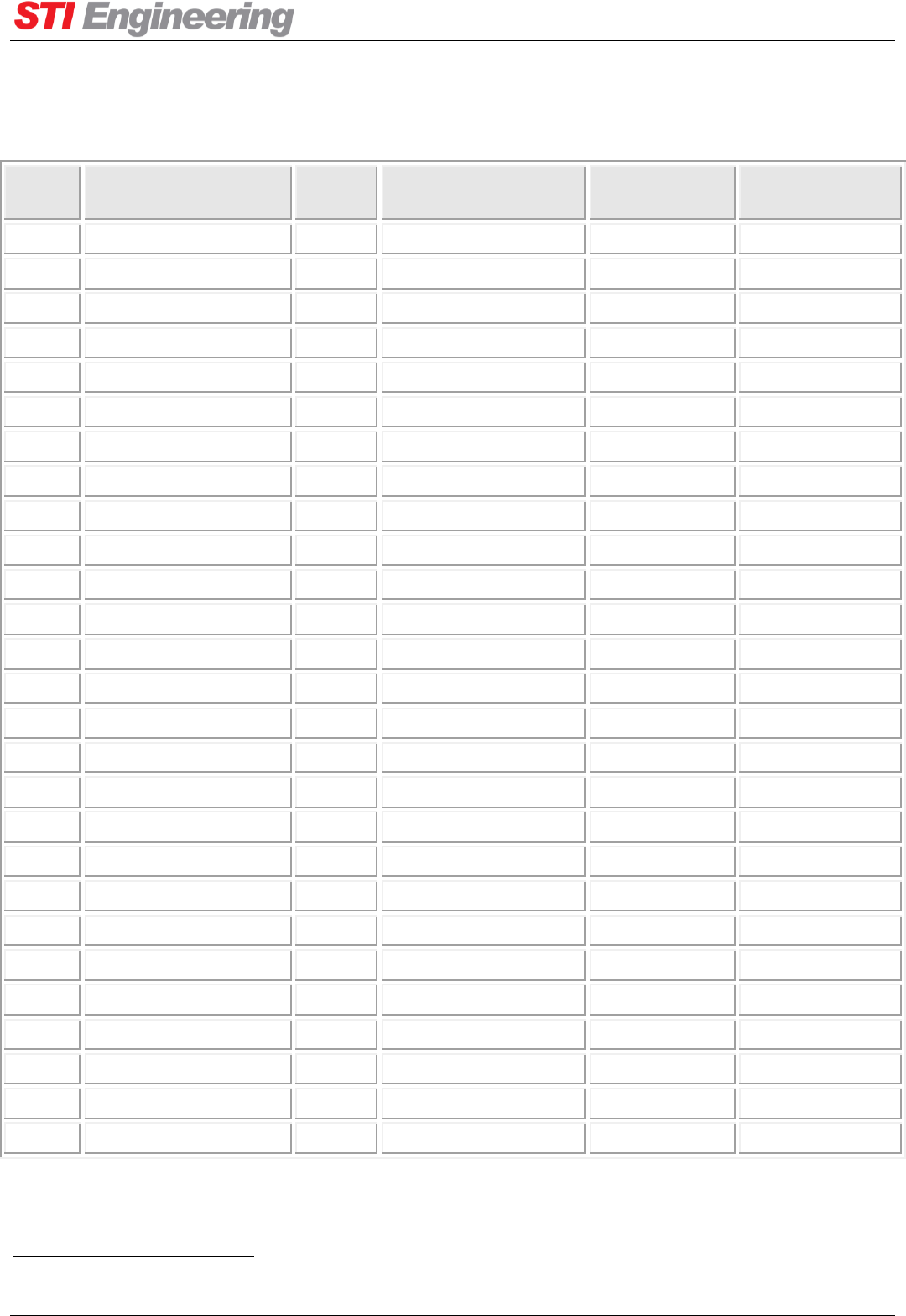
Appendix E Sensor and Fault List Reference
RFI-148 & RFI-900 High Output Power Paging Transmitters User Manual Page 88 of 99
Appendix E Sensor and Fault List Reference
Index
Sensor
Unit
Range
Default Upper
Cut-off
Default Lower
Cut-off
0
PA Temp
ºC
-40 to 126
75
-20
1
Driver Temp
ºC
-40 to 126
70
-20
2
PA Ambient Temp
ºC
-40 to 126
70
-20
3
Isolator Temp
ºC
-40 to 126
60
-20
4
Baseband Temp 1
ºC
-40 to 126
60
-20
5
Baseband Thermistor
ºC
-42 to 152
60
-20
6
Baseband Voltage
mV
0 to 32991
49000
46500
7
24V Voltage
mV
0 to 14833
25930
23040
8
5V Voltage
mV
0 to 6649
5380
4810
9
3.3V Voltage
mV
0 to 4347
3510
3170
10
Baseband Current
mA
0 to 3296
2490
40
11
24V Current
mA
0 to 3296
3110
200
12
5V Current
mA
0 to 2197
2640
800
13
3.3V Current
mA
0 to 3296
1130
670
14
PA0 Current3
mA
0 to 24951
7330
4500
15
PA90 Current3
mA
0 to 24951
7330
4500
16
Driver Current
mA
0 to 2495
390
90
17
Supply Current3
mA
0 to 30742
16170
40
18
Rear Fan Current
mA
0 to 1636
470
50
19
Front Fan Current
mA
0 to 1636
470
50
20
Rear Fan Speed
RPM
0 to 32767
4440
1320
21
Front Fan Speed
RPM
0 to 32767
4440
1320
22
Reverse Power3
mW
0 to 86000
1730
0
23
Transmit Power3
mW
0 to 650000 (typical)
281000
222000
24
Driver Power3
mW
0 to 1714000
2640
800
25
Exciter Power
mW
0 to 21977
680
220
26
Isolator VSWR
10-3:1
0 to 9000
2500
0
Table 23: Sensor Reference
3
Measurement varies according to Tx Power – these values apply to Tx Power = 250W.
Appendix E Sensor and Fault List Reference
RFI-148 & RFI-900 High Output Power Paging Transmitters User Manual Page 89 of 99
Index
Fault
Latching
Default Fault Action
Default Alarm
0
High PA Temperature
Configurable
Disable Transmit
ALM7
1
High Driver Temperature
Configurable
Disable Transmit
ALM7
2
High PA Ambient
Temperature
Configurable
None
ALM7
3
High Isolator Temperature
Configurable
Disable Transmit
ALM7
4
High Baseband 1 Temperature
Configurable
None
ALM7
5
High Baseband 2 Temperature
Configurable
None
ALM7
6
High Baseband Voltage
Configurable
None
ALM1
7
High 24V Voltage
Configurable
None
ALM1
8
High 5V Voltage
Configurable
None
ALM1
9
High 3.3V Voltage
Configurable
None
ALM1
10
High Baseband Current
Configurable
None
ALM1
11
High 24V Current
Configurable
None
ALM1
12
High 5V Current
Configurable
None
ALM1
13
High 3.3V Current
Configurable
None
ALM1
14
High PA0 Current
Configurable
Disable Transmit
ALM1
15
High PA90 Current
Configurable
Disable Transmit
ALM1
16
High Driver Current
Configurable
None
ALM1
17
High Supply Current
Configurable
None
ALM1
18
High Rear Fan Current
Configurable
None
ALM8
19
High Front Fan Current
Configurable
None
ALM8
20
High Rear Fan RPM
Configurable
None
ALM8
21
High Front Fan RPM
Configurable
None
ALM8
22
High Reverse Power
Configurable
Disable Transmit
None
23
High Transmit Power
Configurable
Disable Transmit
ALM4
24
High Driver Power
Configurable
None
None
25
High DDS Power
Configurable
None
ALM4
26
High Isolator VSWR
Configurable
Disable Transmit
ALM6
27
Low PA Temperature
Configurable
None
None
28
Low Driver Temperature
Configurable
None
None
29
Low PA Ambient Temperature
Configurable
None
None
30
Low Isolator Temperature
Configurable
None
None
31
Low Baseband 1 Temperature
Configurable
None
None

Appendix E Sensor and Fault List Reference
RFI-148 & RFI-900 High Output Power Paging Transmitters User Manual Page 90 of 99
32
Low Baseband 2 Temperature
Configurable
None
None
33
Low Baseband Voltage
Configurable
None
ALM1
34
Low 24V Voltage
Configurable
None
ALM1
35
Low 5V Voltage
Configurable
None
ALM1
36
Low 3.3V Voltage
Configurable
None
ALM1
37
Low Baseband Current
Configurable
None
ALM1
38
Low 24V Current
Configurable
None
ALM1
39
Low 5V Current
Configurable
None
ALM1
40
Low 3.3V Current
Configurable
None
ALM1
41
Low PA0 Current
Configurable
None
ALM1
42
Low PA90 Current
Configurable
None
ALM1
43
Low Driver Current
Configurable
None
ALM1
44
Low Supply Current
Configurable
None
ALM1
45
Low Rear Fan Current
Configurable
None
ALM8
46
Low Front Fan Current
Configurable
None
ALM8
47
Low Rear Fan RPM
Configurable
None
ALM8
48
Low Rear Fan RPM
Configurable
None
ALM8
49
Low Reverse Power
Configurable
None
None
50
Low Transmit Power
Configurable
None
ALM5
51
Low Driver Power
Configurable
None
None
52
Low DDS Power
Configurable
None
None
53
Low Isolator VSWR
Configurable
None
None
54
External Reference Fail
Configurable
Reference Switchover
ALM2
55
Software Fault
Configurable
None
None
56
Exciter Out-of-Lock
Configurable
Disable Transmit
ALM9
57
Efficiency Warning
Configurable
None
None
58
Transmit Timeout
Latch-only
Disable Transmit
None
59
Encoder Data Idle
Configurable
None
None
60
PA Current Foldback
Configurable
None
None
61
Reverse Power Foldback
Configurable
Disable Transmit
None
62
Invalid Calibration
Latch-only
Disable Transmit
None
63
Watch Dog Reset
Latch-only
None
None
64
Assertion Reset
Latch-only
None
None
65
Firmware Update Exception
Latch-only
None
None

Appendix E Sensor and Fault List Reference
RFI-148 & RFI-900 High Output Power Paging Transmitters User Manual Page 91 of 99
66
Mass Storage
Configurable
None
None
67
Module
Latch-only
Disable transmit
None
68
Reference Switchover
Latch-only
None
ALM3
69
Disable Transmission
Latch-only
None
None
70
Scale Transmit Power
Latch-only
None
None
71
Enable PA0 Current Foldback
Latch-only
None
None
72
Enable PA90 Current
Foldback
Latch-only
None
None
73
Enable Reverse Power
Foldback
Latch-only
None
None
Table 24: Fault Reference

Appendix F Product Identification Table
RFI-148 & RFI-900 High Output Power Paging Transmitters User Manual Page 92 of 99
Appendix F Product Identification Table
Table 25 shows the Paging Transmitter product identification. The green shaded items are the available
configurations. This table should be used when ordering a Paging Transmitter.
FREQUENCY
BAND
MAXIMUM TX
POWER
POWER
SUPPLY
INTEGRATED
ISOLATOR
RELEASE
OTHER
FEATURES
148
VHF
250
250 W
E
24 VDC
ND
Not Fitted
A
Australia and
US
H
Hot standby
operation
900
UHF
T
-48 VDC
CD
Fitted
E
Europe
P
110/240
VAC
Table 25: Paging Transmitter product identification table
For example, the product code for a 250 W Paging Transmitter supplied from -48 VDC, with an integrated
isolator and released for Europe is RFI-148 250TCDE.

Appendix G Troubleshooting
RFI-148 & RFI-900 High Output Power Paging Transmitters User Manual Page 93 of 99
Appendix G Troubleshooting
This section outlines steps that can be taken in response to issues with the paging transmitter.
G.1 Configuring Sensor Cutoffs
Changing the paging transmitter transmit power should also include changing the sensor cutoffs. The factory
default settings for the paging transmitter is for 20 W transmit power, including reasonable sensor cutoffs for
this transmit power. If the transmit power is increased, then the sensor cutoffs also need to be similarly
increased. Please contact STI Engineering for accessing Cruise Control configuration files with
recommended sensor cutoffs for common transmit power settings.
G.2 Fault LED Active
The paging transmitter has several different indicators that a fault is currently active. The easiest method to
determine fault status is to observe the front panel of the unit. If the red fault LED is on then the transmitter
has an active fault. The fault status can also be interrogated using Cruise Control.
To determine the type of fault that is active, connect to the paging transmitter using Cruise Control (for
information on using Cruise Control see section 3.2). The front serial port of the paging transmitter has a
configuration locked to 19200 8N1 (19200 baud, 8 data bits, even parity, and 1 stop bit). Once connected
with Cruise Control, navigate to the Faults group and Cruise Control will display a view similar to the one
shown in Figure 19 below.
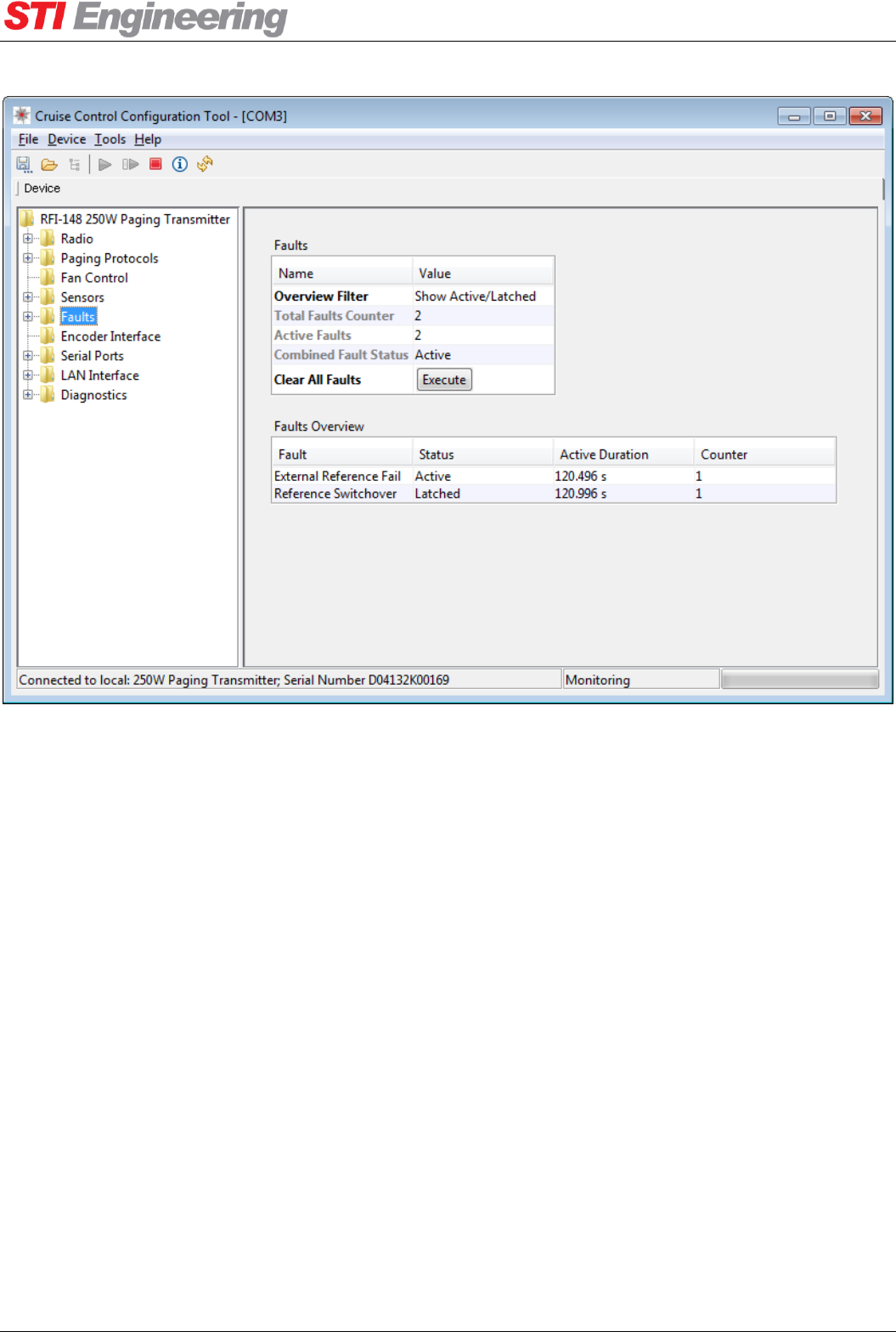
Appendix G Troubleshooting
RFI-148 & RFI-900 High Output Power Paging Transmitters User Manual Page 94 of 99
Figure 19: Cruise Control Faults Overview
In the case of Figure 19, the external reference fail and reference switchover faults are active. See the
headings below to diagnose some common active faults.
G.2.1 External Reference Fail
The external reference fail fault goes active when the transmitter is configured to use the external reference,
but it cannot be locked to.
If an external reference is not in use, change the reference mode to internal and then run the clear all faults
routine to clear the fault LED.
If an external reference is required:
Ensure the external reference is plugged in.
Ensure the external reference is within specification (see Table 9).
Ensure the external reference frequency is configured correctly.

Appendix G Troubleshooting
RFI-148 & RFI-900 High Output Power Paging Transmitters User Manual Page 95 of 99
G.2.2 High Transmit Power
A high transmit power fault could indicate a hardware issue, however it is usually due to incorrect
configuration. The high transmit power fault will go active when the sensed transmit power exceeds the
transmit power upper cutoff. A high transmit power fault is usually seen in tandem with high PA current and
foldback faults.
If the transmit power setting has been increased without changing the sensor cutoff values then this is likely
the cause of the fault. See appendix G.1 for troubleshooting sensor cutoffs. For information on sensor cutoffs
see section 0.
G.2.3 High VSWR
The high VSWR fault goes active when there is too much power being reflected into the RF out connection.
When diagnosing a VSWR fault ensure the guidelines on human exposure to RF emissions are followed in
section 0. To diagnose a high VSWR fault:
Ensure an antenna is attached to the RF out port.
Ensure the paging transmitter is configured for the correct operating frequency and the correct
channel number is selected.
Ensure the antenna is tuned to the operating frequency.
o Also ensure any in-line devices (such as a cavity filter) are tuned to the correct frequency.
Ensure there are no open circuits in the cable run from the paging transmitter to the antenna.
If possible, visually inspect the antenna for damage.
G.2.4 Disable Transmit
The disable transmit fault is a fault action automatically performed by the firmware due to other faults being
active. The disable transmit fault action is caused by critical faults in the paging transmitter to stop hardware
damage or transmitting off frequency. A list of faults that will cause disable transmit and how to
troubleshoot them follows.
G.2.4.1 High PA or Driver Temperature
The temperature on the PA module has exceeded the sensor cutoff values (80 °C by default). To
troubleshoot high PA temperature:
Ensure the fans are configured to turn on at a reasonable temperature. The factory default is
recommended and has the fans turn on at 40 °C.
Check the ambient air temperature where the paging transmitter is installed. When transmitting at
250 W with an ambient temperature of 60 °C, the paging transmitter is expected to reach 80 °C.
Ensure proper air circulation and/or air conditioning in the area the paging transmitter is installed.

Appendix G Troubleshooting
RFI-148 & RFI-900 High Output Power Paging Transmitters User Manual Page 96 of 99
Ensure the fans are working. Check for blockages of the fan intake and exhaust.
G.2.4.2 High Reverse Power or Reverse Power Foldback
A high reverse power fault indicates a hardware failure of the circulator inside the paging transmitter. Failure
of the circulator can cause RF spectrum splatter, so transmit is disabled. Return the unit to STI Engineering
for repair.
G.2.4.3 Exciter Out-of-Lock
An exciter out-of-lock fault indicates that the channel frequencies can no longer be generated. There are two
possible causes of an exciter out-of-lock:
If an external reference is in use: the external reference frequency has drifted too far from the
configured reference frequency. Check the accuracy of the external reference.
A critical hardware failure in the paging transmitter. Return the unit to STI Engineering for repair.
G.2.4.4 Transmit Timeout
The transmit timeout fault goes active when the unit has been transmitting for longer than the transmit
timeout duration. The transmit timeout fault can either be disabled, or the timeout can be increased.
G.3 Unit Won’t Transmit
There could be several causes for the paging transmitting not transmitting, each is explained below.
G.3.1 PTT Override
The paging transmitter PTT override can disable the transmitter from transmitting. The status of PTT
override is displayed in the PTT Override Status field under the radio settings:
Enabled: Transmitting is enabled.
DISABLED:User: Transmitting is disabled because the user-configurable option PTT Override is set
to disable transmit. To enable transmit again, set PTT override to enable transmit.
DISABLED:Fault: Transmitting is disabled because the disable transmit fault action is active. See
section G.2.4 for troubleshooting a disable transmit fault action.
DISABLED:Listening: Transmitting is disabled because the isolator mode is set for listening. To
enable transmitting again, the isolator mode must be set for transmitting.
DISABLED:Loading Config: Transmitting is disabled while Cruise Control is loading a
configuration file.

Appendix G Troubleshooting
RFI-148 & RFI-900 High Output Power Paging Transmitters User Manual Page 97 of 99
G.3.2 Hardware or Auto PTT
When troubleshooting hardware or auto PTT, ensure the following:
The paging transmitter can transmit with the “Transmit On” routine in Cruise Control.
Hardware PTT or auto PTT is enabled.
For hardware PTT:
The correct hardware PTT active level is configured, active low or active high.
Toggling the hardware PTT state is reflected in the “Ext I/O” table in Cruise Control in the Encoder
Interface group. If this does not work, it indicates a cabling issue with the hardware PTT input.
For auto PTT:
Toggling the L-bit state is reflected in the “Ext I/O” table in Cruise Control in the Encoder Interface
group. If this does not work, it indicates a cabling issue with the L-bit input.
G.3.3 Profile Definition
If the RFI-900 reports that it is transmitting (Radio → Power → Transmitter Status), yet LIU L-Bit activity
does not produce modulated data, ensure that the selected modulation profile (Encoder Interface → Active
Profile) is not configured to use an external data clock (via the LIU) unless you are providing one (Paging
Protocols → Profiles → Ext. Data Clock).
G.4 Unit Transmits at Low Power
If the unit is transmitting at low power as indicated by the front panel power gauge or transmit power sensor
there could be several causes. Ensure:
The required transmit power is configured.
There are no faults active. A unit configured to transmit at a high power level needs similarly higher
sensor cutoffs, see appendix G.1.
Otherwise, low transmit power could indicate a hardware failure. If troubleshooting fails, return the unit to
STI Engineering for repair.

Appendix H Glossary
RFI-148 & RFI-900 High Output Power Paging Transmitters User Manual Page 98 of 99
Appendix H Glossary
BNC
Bayonet Neill-Concelman (Connector)
CTS
Clear To Send
DCD
Data Carrier Detect
DCE
Data Communications Equipment (radio modem)
DTE
Data Terminal Equipment (computer device)
DTR
Data Terminal Ready
EIRP
Effective Isotropic Radiated Power
GUI
Graphical User Interface
PA
Power Amplifier
POCSAG
Post Office Code Standardisation Advisory Group
PET
Motorola Page Entry (now TAP)
PTT
Push-To-Talk
RF
Radio Frequency
RSSI
Received Signal Strength Indicator
RTS
Request To Send
Rx
Received
SNMP
Simple Network Management Protocol
SNTP
Simple Network Time Protocol
TAP
Telelocator Alphanumeric Protocol (formerly PET)
TNC
Threaded Neill-Concelman (Connector)
TNPP
Telelocator Network Paging Protocol
Tx
Transmitted
UTC
Coordinated Universal Time
VHF
Very High Frequency
VSWR
Voltage Standing Wave Ratio
Table 26: Glossary

RFI-148 & RFI-900 High Output Power Paging Transmitters User Manual Page 99 of 99
Index
Appendix
Controller Configurations
Glenayre C2000 Controller / FLEX Mode ............... 48
Glenayre C2000 Controller / POCSAG Mode .......... 48
Motorola NIU Controller / FLEX Mode ................... 48
Zetron Model 66 Controller / POCSAG Mode ......... 49
Configuration ..................................................................... 13
Auto PTT ....................................................................... 24
Carrier Offset ................................................................. 27
Channel Selection .......................................................... 22
Combined Fault ............................................................. 31
Default Reference .......................................................... 25
Delay Correction ........................................................... 25
Encoder Frequency Control ........................................... 20
Encoder Hardware PTT ................................................. 20
Encoder Protocol Control .............................................. 20
External Reference ........................................................ 25
Isolator Mode ................................................................ 26
Minimum Fault Duration ............................................... 31
PTT System Override .................................................... 24
PTT Turn Off Delay ...................................................... 24
Sensor Cut-off ............................................................... 29
Serial Ports .................................................................... 21
SNTP ............................................................................. 33
Transmit Power ............................................................. 22
Transmit Timeout .......................................................... 24
Diagnostics and Troubleshooting
Serial Port Statistics ...................................................... 21
Fault Reference .................................................................. 88
Glossary ............................................................................. 98
Installation
Product ............................................................................ 8
Introduction .......................................................................... 6
Operation ............................................................................ 21
Serial Ports .................................................................... 21
Sensor Reference ................................................................ 88
Technical Specifications .................................................... 42
Paging Transmitter ........................................................ 42
Serial Ports .................................................................... 45