STONEX SRL STN21 GPS SURVEYING EQUIPMENT User Manual
STONEX SRL GPS SURVEYING EQUIPMENT Users Manual
Users Manual

Contents
Page 1 of 9

Contents
Page 2 of 9
Contents
Chapter
I
:
A
brief
introduction
of
S9
......................................................................................
3
Chapter
II
:
S9
mainframe
..........................................................................................................6
II.1 The outlook of mainframe........................................................................................................... 6
II.2 Indicator lights and instrument setup....................................................................................... 6

Contents
Page 3 of 9
Chapter I : A brief introduction of S9
STONEX® devoted itself to offer to surveyors the most advanced GPS tools they need.
GPS RTK surveying technology plays an important role in surveying work
and its use is getting more and more widespread. As a leading
GPS RTK instrument produced, STONEX® guarantees the S9, its latest
RTK GPS receiver, is suited for the requests of precision, reliability and user
friendliness of nowadays.
S9 is able to receive both frequencies of GPS signal, but also
satellite signals from GLONASS and GALILEO, so we must correctly speak of
“GNSS” receiver.
S9 mainframe is integrated with GNSS antenna, GNSS module, Bluetooth device
and battery. S9 is totally integrated: that means that the surveyor only needs
the handheld to start its job.
The exquisite outlook and the amazing color bring you a fashioned surveying
situation. The design has a higher stability, less power losing, smaller
volume and lighter weight than the previous STONEX® receivers. S9 has a
special design which makes it waterproof, dustproof and quakeproof. The
batteries and built‐in radio are set in the bottom of mainframe, giving
more effective dustproof and waterproof qualities, and making S9 a better
performer in field surveying. Wireless receiver unit weights 1.2 kg: the rover is light and
easy to carry. The low power losing of receiver allows the single battery to meet a long
time workability. Integrated design and anti‐jamming property are combined
perfectly: the former avoids the problem of a cumbersome external antenna, and
the mainframe design can resolve the jamming problem effectively.
The performance of data‐transfer radio technology is at the same level
of international advanced technology: the bit error rate (BER) is 10‐7 and
the radio collision problem is reduced.
Contents
Page 4 of 9
The S9 receiver mount a GPS/GLONASS antenna with a four feed technology. This
design is able to reduce the electrical phase center error ellipsoid and in addiction it
improves the Right Hand Circular Polarization Characteristics (RHCP) of the
antenna, resulting in enhanced GPS signal tracking and improved multipath
rejection, in case a polarization reversal has taken place as a result of the signal
reflection.
The embedded receiver firmware can customize different RTK software
for different applications. The data transfer is easy and fast, like a Plug and Play USB
drive. STONEX® provide S9 receivers with a two year complete international warranty .
to the operational temperatures, limits which should not be exceeded
for a correct functioning.
It is also important to point out that in each weather case after coming back from the
field.
you should keep open the container in a warm and dry place and in the same time taking
out the controller and receiver out from the container, in order to make them dry.
Anyway we recommend you to treat the instrument with reasonable care.
Even if you have used other GPS or GNSS products before, we recommend that you
spend some time reading this manual to learn about the special features of this product.
If you are not familiar with GNSS technology, we suggest to read a specific book in order
to better understand the contents of this manual. Anyway you can ask for any technical
support to our address
support@stonexesurveying.com
or contact your local dealer.
Contents
Page 5 of 9
Chapter II : S9 mainframe
II.1
The
outlook
of
mainframe
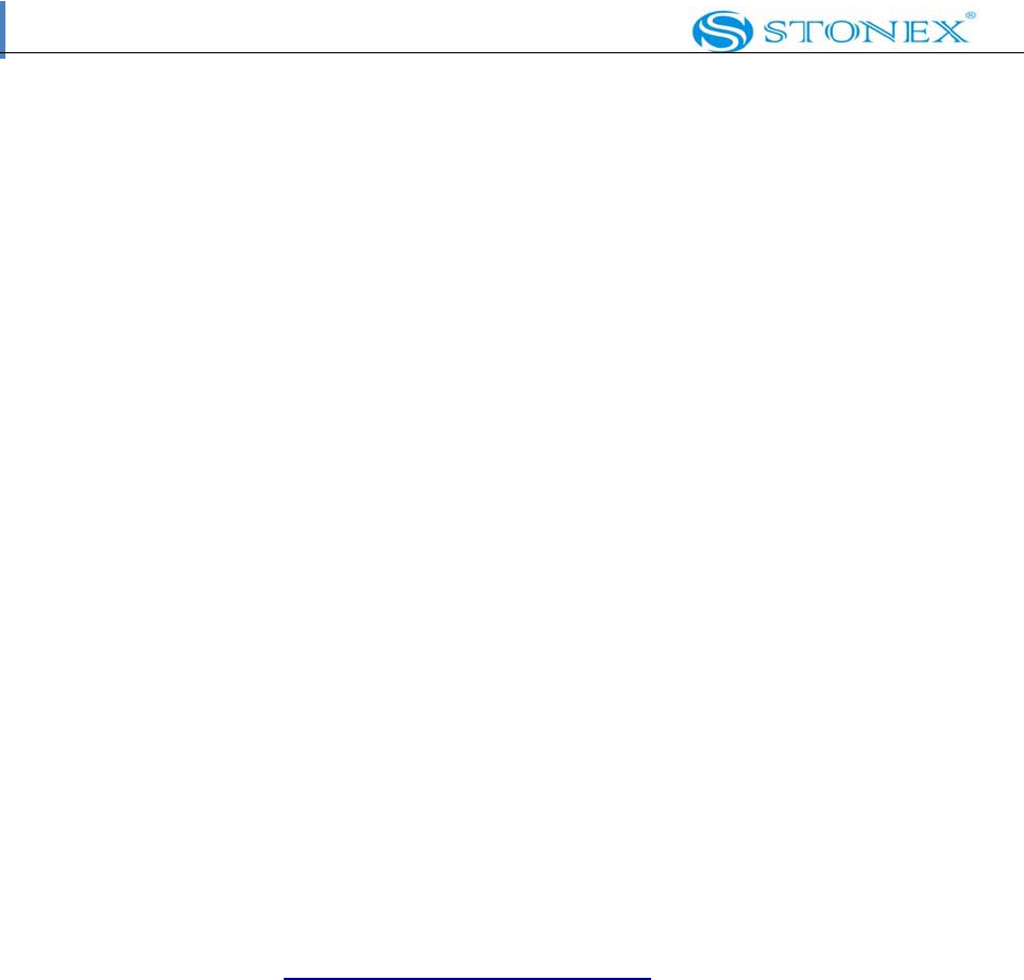
The mainframe has an almost cylindrical shape, with a base larger than the height.
There are three parts: an upper cap, a rubber loop and the main
structure. The upper cap protects the GNSS antenna placed inside. The
rubber loop has the function of softening possible blows or falls. In the front side of
the main structure there are keys and lights, on the bottom side there are one slot for the
battery. All the others components of the receiver (Bluetooth device, main board, etc.)
are contained inside the main structure.
Fig. 2.1 ‐ S9
mainframe
II.2
Indicator
lights
and
instrument
setup
3 5 7
1 2
4 8
6
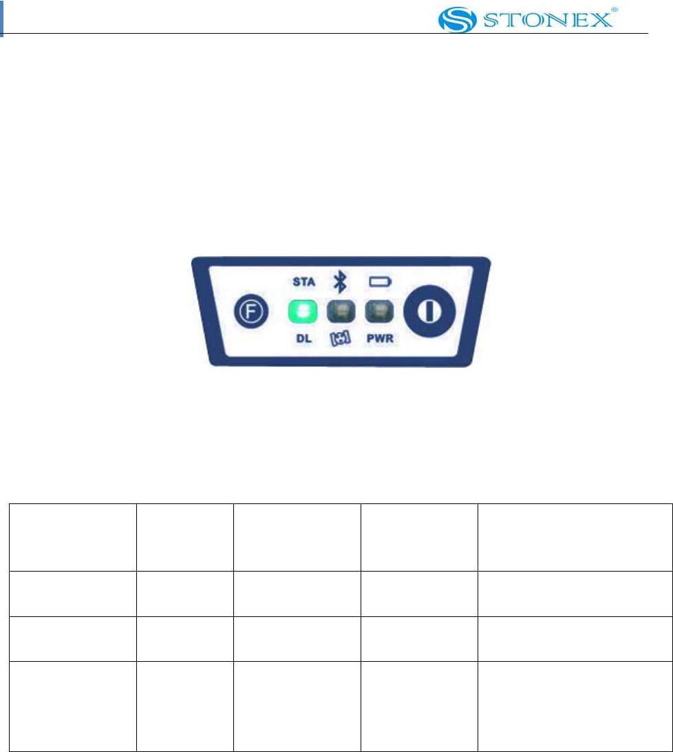
Fig. 2.2 ‐ S9 keys and indicator lights

Contents
Page 6 of 9
1. Function Key
2. Power Key
3. Status light
4. Data link light
5. Bluetooth light
6. Satellite light
7. Built‐in power supply light
8. External power supply
As you see in figure 2.2 there are three indicator lights, each one with two different colors
Refer red to two different functions:
From the left to the right:
1st indicator: status indicator light (red), data link indicator light (green)
2nd indicator: Bluetooth indicator light (red), satellite indicator light (green)
3rd indicator: Battery power light (red), external power supply indicator light
(green). The usages of them are as follows
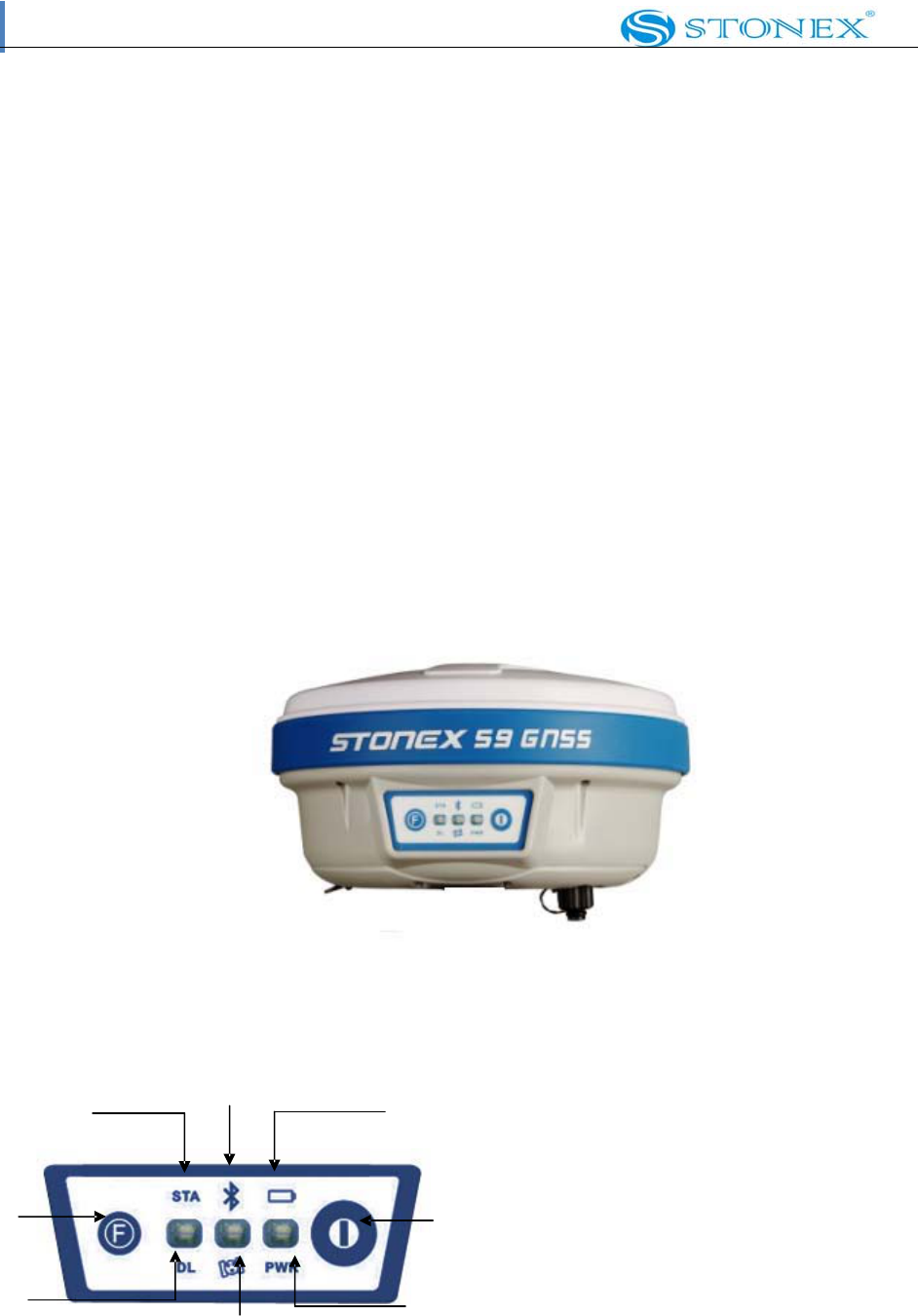
BAT (red): Built‐in power supply light (Fig.2.3).
It includes two kind of status
1. Fixed: electricity supply in good condition.
2. Flashing: lack of electricity.
Usually when the light begins to flash you have still one hour of power
Contents
Page 7 of 9
Fig. 2.3 ‐ S9 built‐in power Light
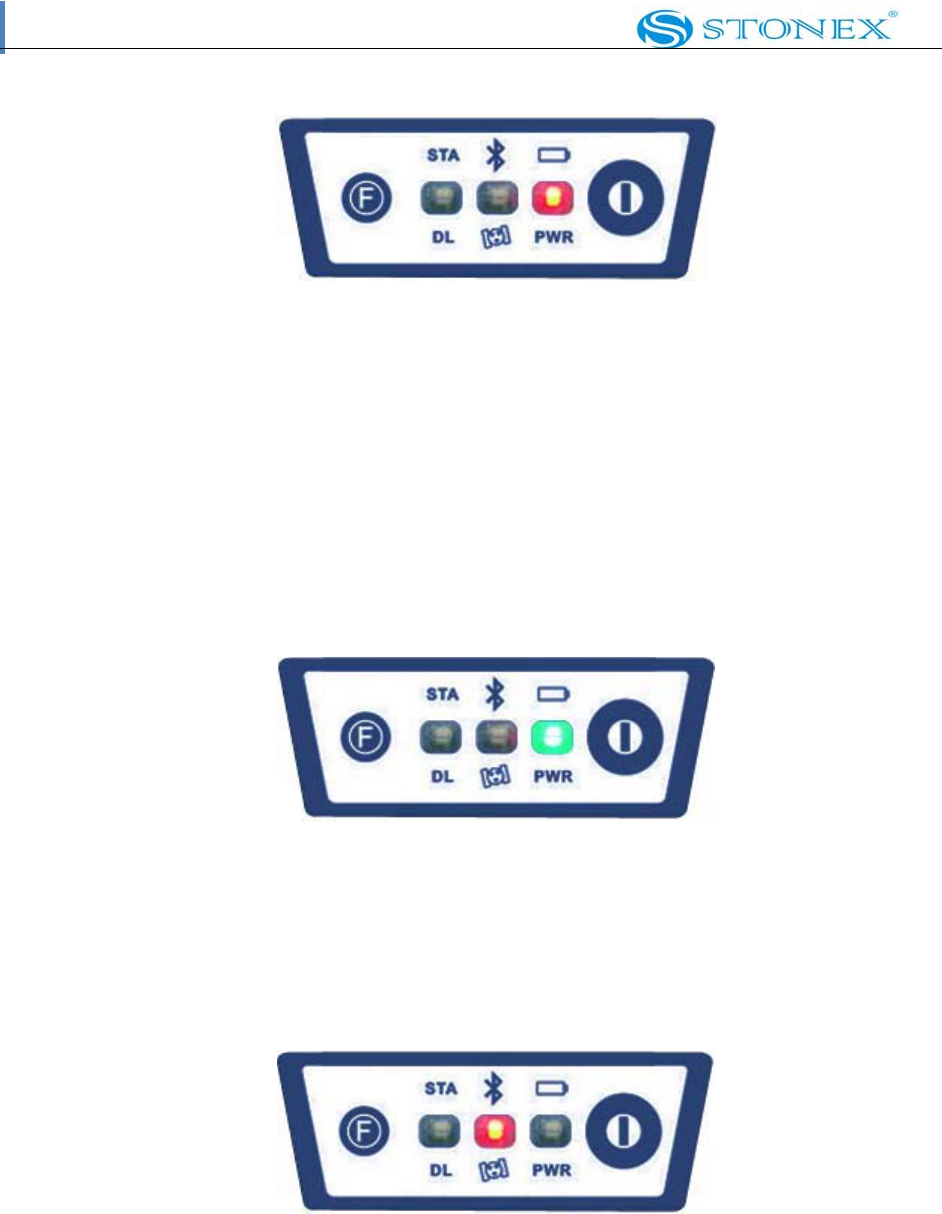
PWR (green): external power supply light
(Fig.2.4). It includes two kinds of status.
1. Fixed: electricity supply in good condition.
2. Flashing: lack of electricity
Fig. 2.4 ‐ S9 external power light
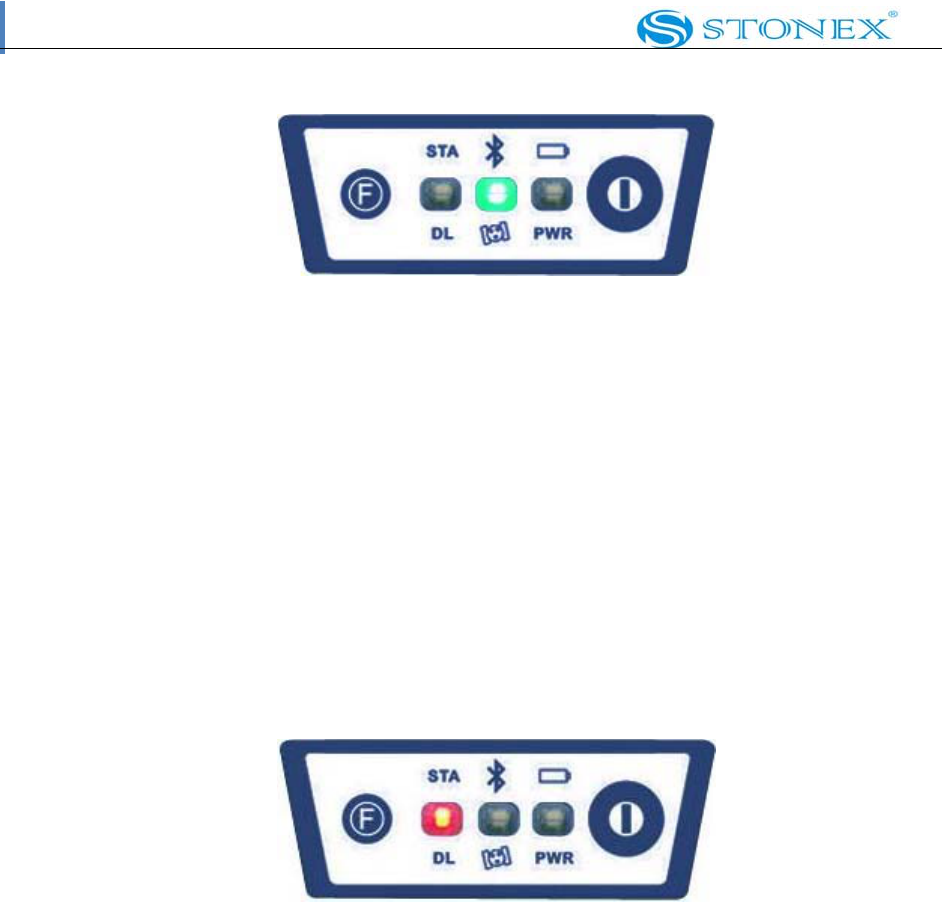
BT (red): Bluetooth indicator light (Fig. 2.5).
Once you have connected controller with receiver, this light will keep.
Fig. 2.5 ‐ S9 Bluetooth light
SAT (green): Satellite light (Fig. 2.6).
It shows the amount of locked satellites, when the receiver gets satellites signal it will
start to blink for a number of times equal to the amount of locked satellites.
Contents
Page 8 of 9
Fig. 2.6 ‐ S9 satellite light
STA (red): Status light (Fig. 2.7).
In static mode, its blinking means that the receiver is recording data. In
base mode its blinking means that base is transmitting data. In rover
mode and GPS data link, its blinking after connection shows that the data link
module is working in good condition.
Fig. 2.7 ‐ S9 status
light
Contents
Page 9 of 9
DL (green): Data Link light (Fig. 2.8).
In static mode, it will keep lighted. In rover mode, its blinking shows
that the is receiving corrections. In rover mode , its blinking after
connection means that data link module working in good condition.
Fig. 2.8 ‐ S9 Data Link light
Receiver Mode Power
LED
(red)
Status LED
(red)
Data Link
LED (green)
Satellite LED
(green)
Receiver ON
Healty Power
ON Not relevant Not relevant Not relevant
Receiver ON
Low power
flashing Not relevant Not relevant Not relevant
Logging of
static data
ON Flashing with
frequency of
data sampling
ON Flashing for a
number of times
equal to the
amount of locked
FCC WARNING
This device complies with Part 15 of the FCC Rules. Operation is subject to the following two
conditions:
(1) this device may not cause harmful interference, and
(2) this device must accept any interference received, including interference that may cause
undesired operation.
NOTE 1: Any changes or modifications not expressly approved by the manufacturer could void
the user’s authority to operate the equipment.
NOTE 2: The manufacturer is not responsible for any radio or TV interference caused by
unauthorized modifications to this equipment. Such modifications could void the user’s authority
to operate the equipment.