SUZHOU FOIF A30 GNSS Receiver User Manual A30 receiver V1 0
SUZHOU FOIF CO.,LTD GNSS Receiver A30 receiver V1 0
UserManual.wiki
>
SUZHOU FOIF
>
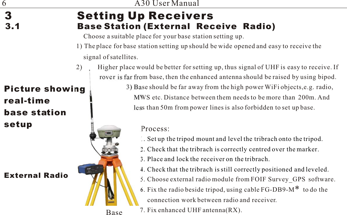
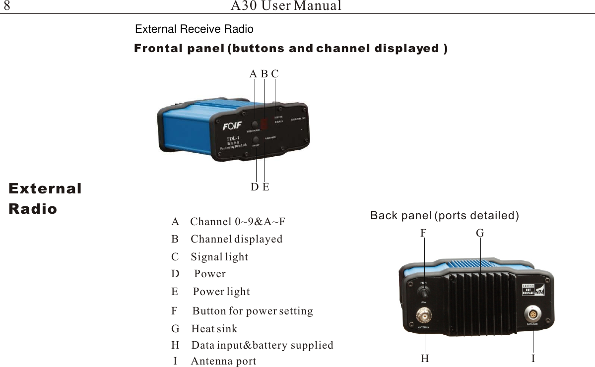
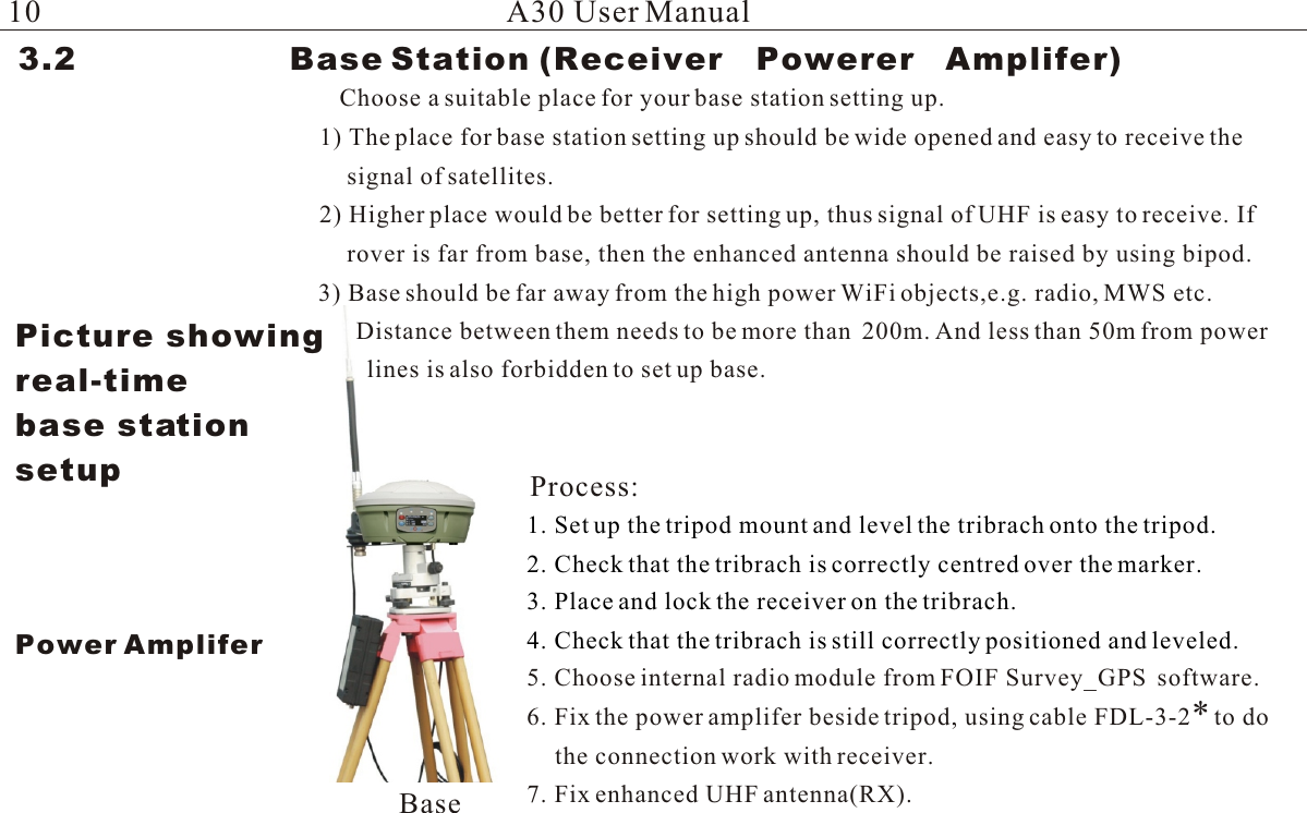
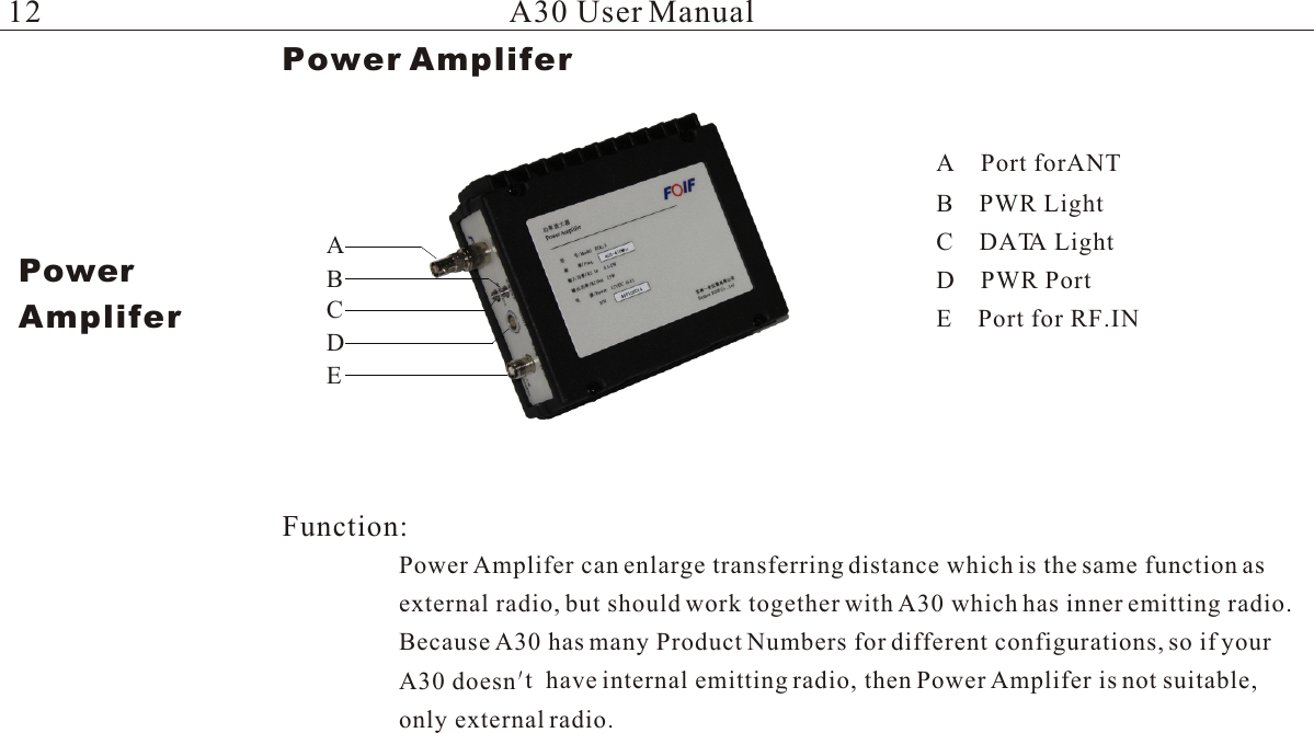
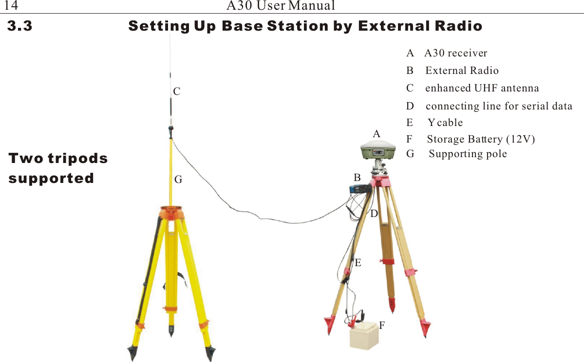
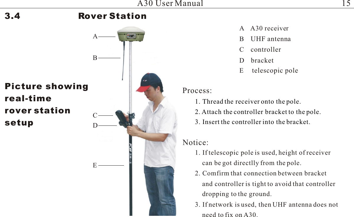
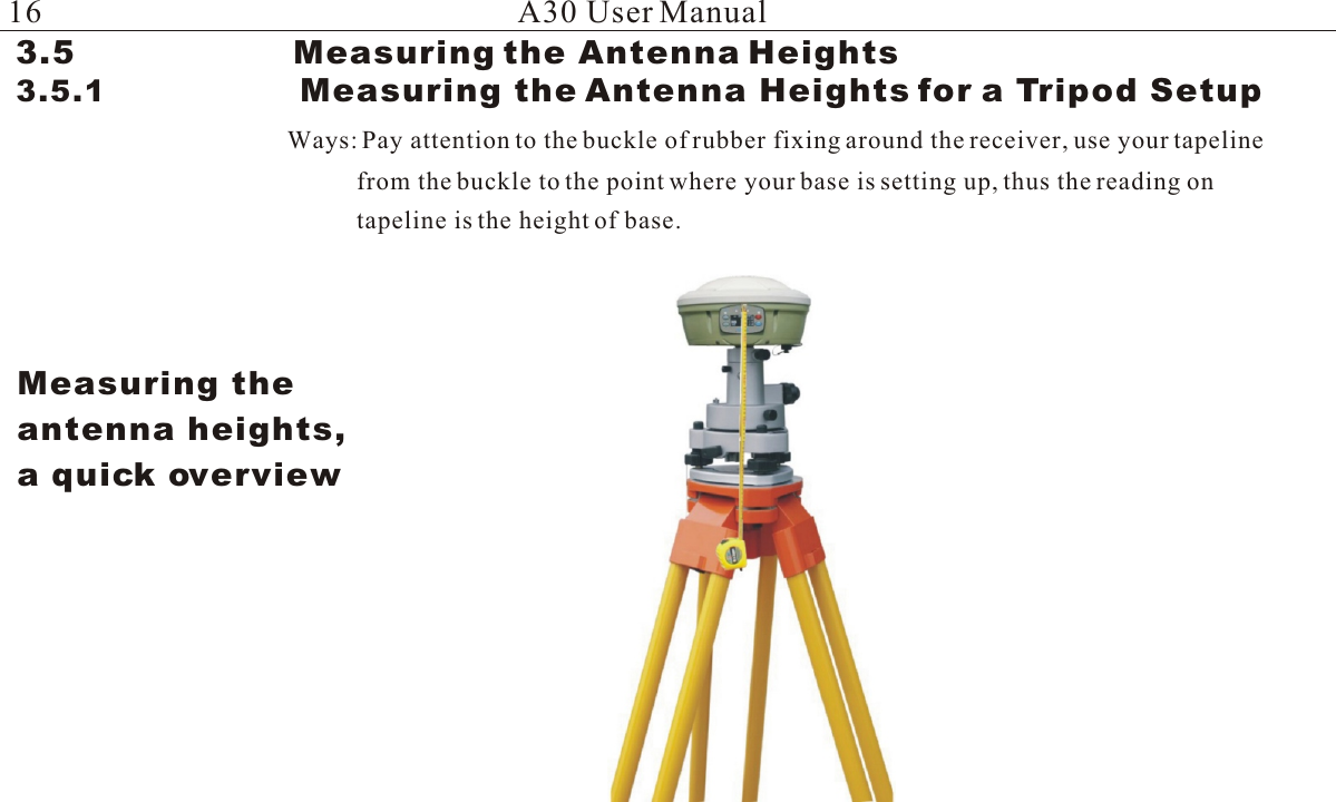
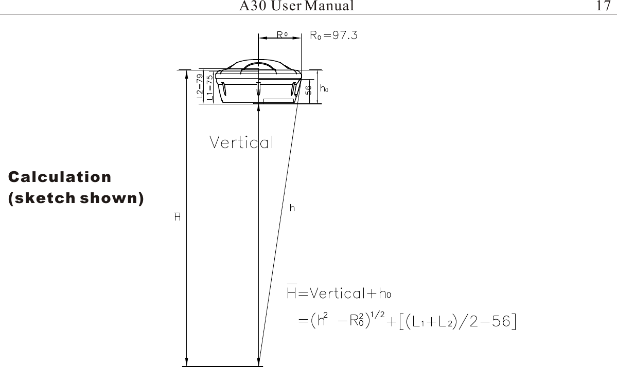
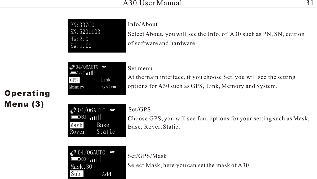
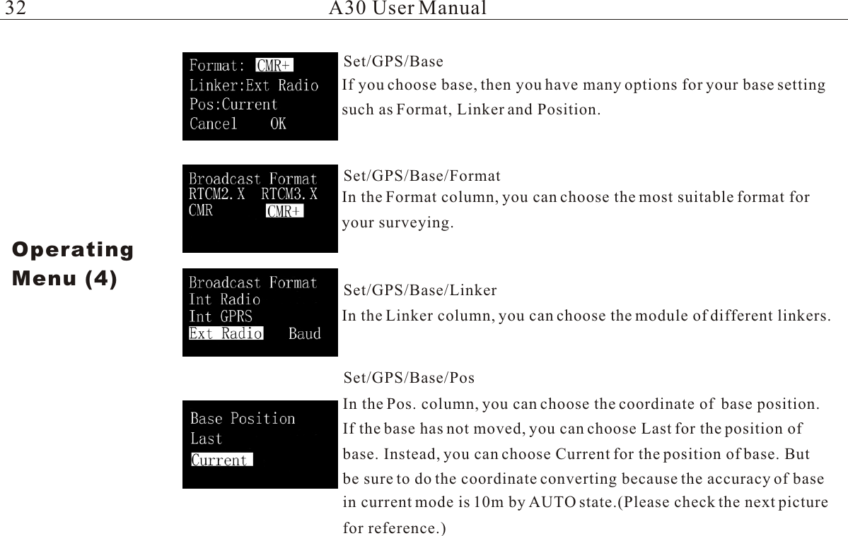
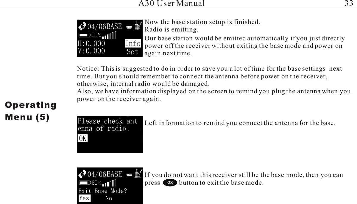
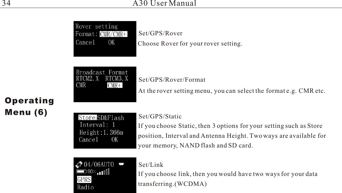
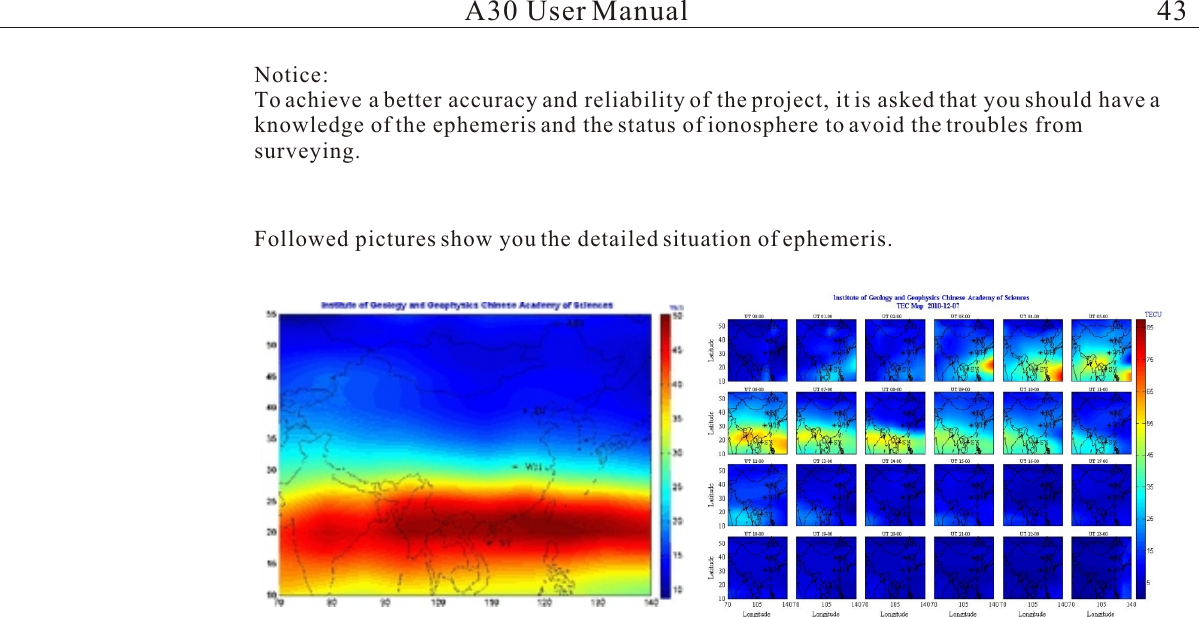
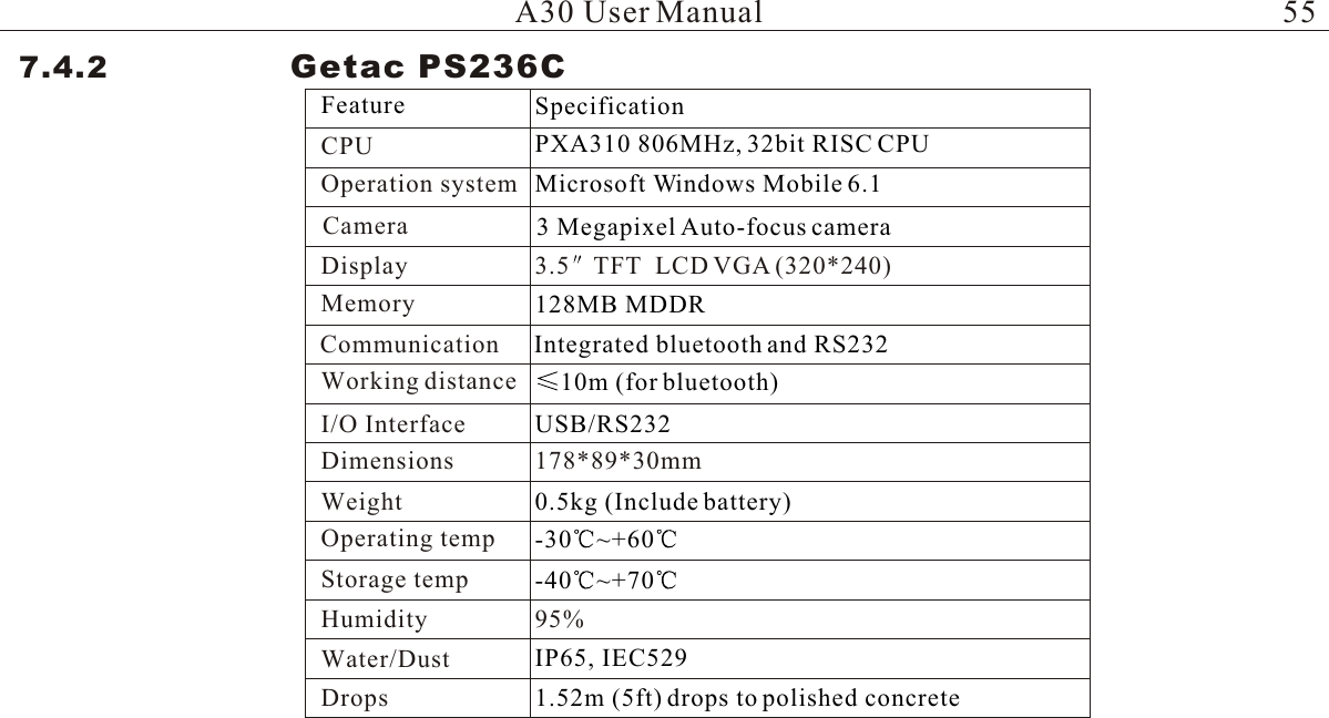
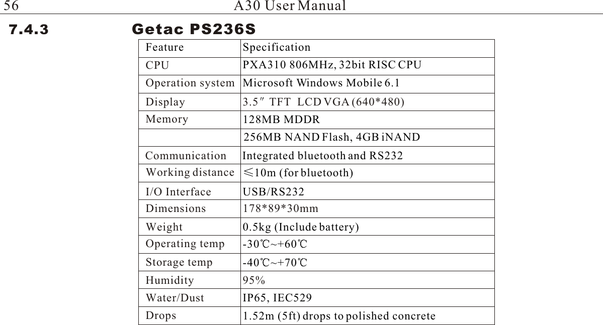
A30 User Manual
Users Manual
Navigation menu
Upload a User Manual
Namespaces
Wiki Guide
HTML
PDF
Info
Views
User Manual
Discussion / Help
Navigation