SUZHOU FOIF RTS352 Total Station User Manual 1
SUZHOU FOIF CO.,LTD Total Station Users Manual 1
Contents
- 1. Users Manual 1
- 2. Users Manual 2
Users Manual 1

RTS 350 Series
Total Station Instruction Manual
RTS352
RTS355
Version1.0e
English
Suzhou FOIF Co., Ltd.
1
Dear Customer:
Congratulations! We, FOIF are proud to present you with an RTS350
instrument. Your total station is a rugged and reliable instrument whose
performance and design are not surpassed.
To fully appreciate and protect your investment, we suggest that you take the
necessary time to read and fully understand this manual. We have a dedicated
service organization. If the need arises, please don’t hesitate to call us.
Thank you for your trust and confidence.
2
NOTE:
Don’t collimate the sun directly
Avoid insolating the instrument, and don’t collimate the sun directly for protecting eyes
and instrument.
Set up the instrument on the tripod
When using it please insure the connection between tripod and instrument is firm. It is
better to work with wooden tripod for the measurement accuracy.
Assemble the tribrach on the instrument
The setting of tribrach would influence the accuracy. The tribrach should be check
frequently, the screw which connects the tribrach and alidade must be locked tightly. And
the central fixing screw should be tight.
Avoiding the librations on the instrument
When transporting, keep the instrument in the case and try your best to lighten librations.
Carry the instrument
When carrying,the instrument handle must be held tight.
High temperature condition
If put the instrument in high temperature condition for a long time, it is bad for the
instrument performance.
Temperature changing sharply
The sharp temperature changing on the instrument or prism will shorten the distance
measurement range, for example, after taking the instrument out from a warm car to a
cold condition, wait for some time, it can be used when it adapts to the surrounding
condition.
Check the battery power
Before using it, you should check the power whether it is enough.
Take out the battery
It is not suggested to take out the battery when the instrument is on, otherwise, the stored
data may be lost, so it is better to replace the battery after power off the instrument.
Stored data responsibility
FOIF should not be held liability for the lost data because of wrong operation.
The noise from the instrument
When the instrument is working, it is normal if you hear the noise from instrument motor,
it will not affect the instrument work.
3
Definition of Indication
For the safety of your product and prevention of injury to operators and other persons as
well as prevention of property damage, items which should be observed are indicated by
an exclamation point within a triangle used with WARNING and CAUTION statements
in this manual.
The definitions of the indication are listed below. Be sure you understand them before
reading the manual’s main text.
PRECAUTIONS FOR SAFE OPERATION
●Only FOIF authorized distributors can disassemble or rebuilt the instrument.
●Do not collimate the sun directly. The eye injury or blind could result.
●Cover the charger maybe result fire when charging.
●If use defection power cable, socket or plug, there is danger of fire, or electronic shock.
●Using wet battery or charger maybe result fire, or electronic shock.
●Do not close the instrument to burning gas or liquid, and do not use the instrument in
coal mine. Blast could be result.
●Do not put the battery in the fire or high temperature condition. Explosion, damage
could result.
●If use the battery which is not specified by FOIF, there is a danger of fire, electric shock
or burn.
●If use the power cable which is not specified by FOIF, there is a danger of fire.
●If short circuit of the battery, there is a danger of fire..
● When this product encounters disturbance of severe Electrostatic Discharge, perhaps it
will have some degradation of performance like switching on/off automatically and so on.
WARNING:
CAUTION:
! WARNING
!
!
Ignoring this indication and making an operation
error could possibly result in death or serious
injury to the operator.
Ignoring this indication and making an operation
error could possibly result in personal injury or
property damage.

4
●If touch the instrument with wet hand, there is danger of electric shock.
●Stand or seat on the carrying case, or turn over the carrying case arbitrarily, the
instrument maybe damaged.
●Be careful of the tripod tiptoe when setup or move it.
●Drop the instrument or the carrying case, or use defective belt, agraffe or hinge,
instrument damage could result.
●Do not touch liquid leaking from the instrument or battery. Harmful chemicals could
cause burn or blisters.
●Please assemble the tribrach carefully, if the tribrach is not stable, series damage could
result.
●Drop the instrument or tripod, series damage could result. Before use it, check the
central screw is tight.
User
1) This product is for professional user only!
The user is required to be a qualified surveyor or have a good knowledge of surveying, in
order to understand the user manual and safety instructions, before operating, inspecting
or adjusting.
2) Wear the required protectors (safety shoes, helmet, etc.) when operating.
Exceptions from Responsibility
1) The user of this product is expected to follow all operating instructions and make
periodic checks of the product’s performance.
2) The manufacturer assumes no responsibility for results of a faulty or intentional usage
or misuse including any direct, indirect, consequential damage, and loss of profits.
3) The manufacturer assumes no responsibility for consequential damage, and loss of
profits by any disaster, (an earthquake, storms, floods etc.).
4) The manufacturer assumes no responsibility for any damage, and loss of profits due to
a change of data, loss of data, an interruption of business etc., caused by using the product
or an unusable product.
5) The manufacturer assumes no responsibility for any damage, and loss of profits caused
by usage except for explained in the user manual.
6) The manufacturer assumes no responsibility for damage caused by wrong transport, or
action due to connecting with other products.
! CAUTION
5
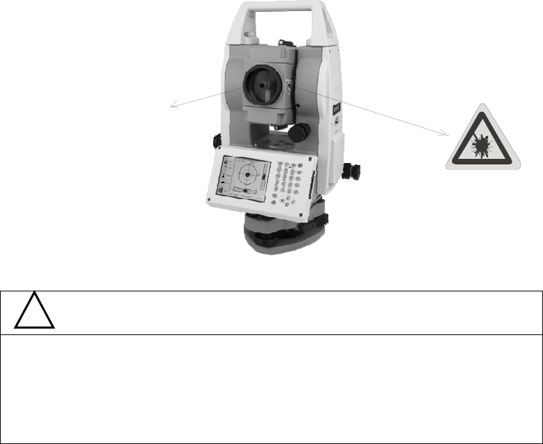
Safety Standards for Laser(RTS series)
RTS350 series adopts the safe and visible laser on the basis of “Specification Standard of
radiant products” (FDA CDRH.21CFR Part 1040.10 and 1040.11) and “Safety of laser
products – parts 1: Equipment classification, requirements and user’s guide” (IEC
60825-1:2001).
According to above standards, RTS350 series is class a/3R laser products. When the Ⅲ
prism or reflective sheet is selected in Config mode as target, the output is equivalent to
the safer class 1.
Once the instrument is damaged, do not disassemble it. You’d better contact FOIF or
local dealer.
Labels
Follow the safety instructions on the labels as well as in this manual to ensure safe use .
Note for Safety
● Never point the laser beam at other’s eyes, it could cause serious injury.
● Never look directly into the laser beam source, it could cause permanent eye damage.
● Never stare at the laser beam, it could cause permanent eye damage.
● Never look at the laser beam through a telescope or other optical devices, it could cause
permanent eye damage.
! WARNING
Laser emit
1
CONTENT
1. Nomenclature and Functions........................................................................................... 1
1.1 Nomenclature............................................................................................................1
1.2 Keyboard................................................................................................................... 3
1.3 Main menu ................................................................................................................4
1.3.1 Basic Measurement ............................................................................................4
1.3.2 STD Measurement(Optional).............................................................................5
1.3.3 Instrument Setup ................................................................................................5
1.3.4 About..................................................................................................................6
1.3.5 Professional field software................................................................................. 6
1.3.6 Convenient panel................................................................................................6
1.4 Shortcut key ..............................................................................................................7
1.5 Touch screen calibration............................................................................................ 8
1.6 Battery.......................................................................................................................9
1.6.1 Battery Power indicator...................................................................................... 9
1.6.2 Replace and mount battery...............................................................................10
1.6.3 Recharge battery............................................................................................... 10
1.7 USB connection....................................................................................................... 11
1.8 Guide light(Optional)..............................................................................................12
2. Preparation before Measurement .................................................................................. 13
2.1 Setting up the instrument......................................................................................... 13
2.2 Levelling-Up ...........................................................................................................13
2.3 Centering.................................................................................................................16
2.3.1 Centering with Optical Plummet (Optional) ....................................................16
2.3.2 Centering with Laser Plummet.........................................................................16
3 Instrument settings......................................................................................................... 17
3.1 INST Setup..............................................................................................................17
3.1.1 Setting the measure condition ..........................................................................18
3.1.2 Setting the units................................................................................................18
3.1.3 Setting parameters of communication ports.....................................................19
3.1.4 Instrument parameters review ..........................................................................19
3.2 Illumination settings................................................................................................20
4. Basic measurement program......................................................................................... 21
4.1 Run the program “Basic Measurement”.................................................................. 21
4.2 Basic measurement screen introduction.................................................................. 21
4.3 Angle measurement mode ....................................................................................... 22
2
4.3.1 Horizontal angle(right angle) and vertical angle measurements ...................... 22
4.3.2 Horizontal angle switch between right and left................................................23
4.3.3 Setting horizontal angle with the “L.Angle” key .............................................24
4.3.4 Setting horizontal angle with the “S.Angle” key.............................................. 25
4.3.5 Setting “vertical angle and percent grade” mode with the “V/%” key............. 26
4.3.6 Carrying out angle retesting with the “Repeat” key.........................................27
4.4 Distance measurement mode...................................................................................31
4.4.1 Distance measurement and measuring mode setting........................................ 31
4.4.2 Fine/Tracking distance measurement............................................................... 32
4.4.3 Accurate Measurement and Track mode ..........................................................34
4.4.4 Exchange of distance units............................................................................... 35
4.4.5 Distance stake out measurement ......................................................................35
4.4.6 Remote Elevation Measurement(REM)......................................................37
4.4.7 Missing Line Measurement (MLM)................................................................. 42
4.4.8 Line-height Measurement.................................................................................45
4.5 Coordinate Measurement Mode .............................................................................. 50
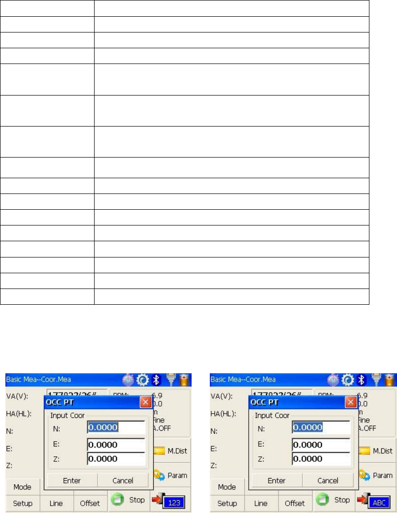
4.5.1 Setting coordinate of occupied point................................................................ 50
4.5.2 Setting backsight point.....................................................................................51
4.5.3 Setting instrument height and prism height...................................................... 53
4.5.4 Operation of coordinate measurement..............................................................54
4.5.5 Traverse Surveying........................................................................................... 55
4.5.6 Offset Measurement Mode...............................................................................58
4.6 About.......................................................................................................................68
5. Check and Adjustment.................................................................................................. 69
5.1 The Instrument Constant ......................................................................................... 69
5.2 Plate Level and Circular Level................................................................................ 70
5.2.1 Plate Level........................................................................................................ 70
5.2.2 Circular Level...................................................................................................70
5.3 The Optical Sight ....................................................................................................71
5.4 Optical Plummet and Laser Plummet......................................................................71
5.4.1 Optical Plummet(factory optional)...................................................................71
5.4.2 Laser Plummet..................................................................................................72
5.5 Vertical Cross-hair on Telescope.............................................................................73
5.6 Horizontal Collimation Error C............................................................................... 74
5.7 Vertical Index Error.................................................................................................75
5.8 EDM Optical Axis and the Telescope Sighting Axis Error .....................................77
6. Specifications................................................................................................................ 78
8. Standard components .................................................................................................... 81
Appendix I: Atmospheric correction formula and chart(Just for reference).................. 82
3
Appendix II: Correction for refraction and earth curvature ..........................................84
Appendix III: Assembling and disassembling for three-jaw tribrach............................85
1
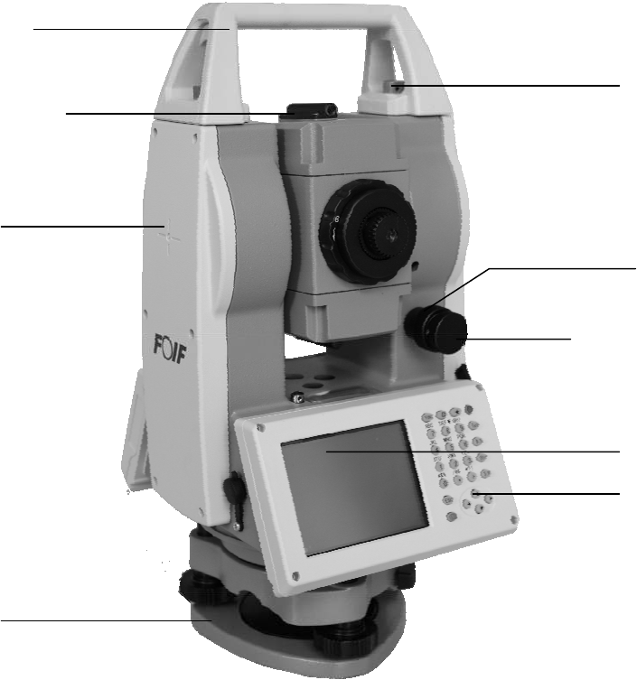
1. Nomenclature and Functions
1.1 Nomenclature
Handle
Optical sight
Touch screen
Tribrach
Keypad
Handle screw
Vertical
motion screw
Vertical
clam
p
screw
Instrument height mark
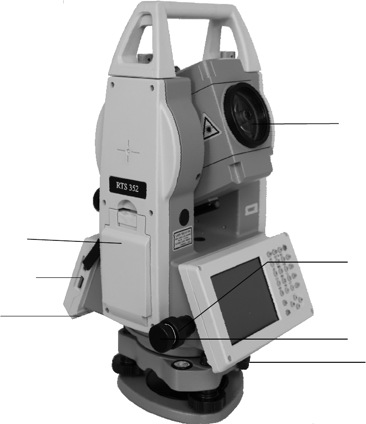
2
Objective
Battery
Touch pen
Tribrach clamp
Horizontal
motion clam
p
Horizontal tangent
screw
USB port
3
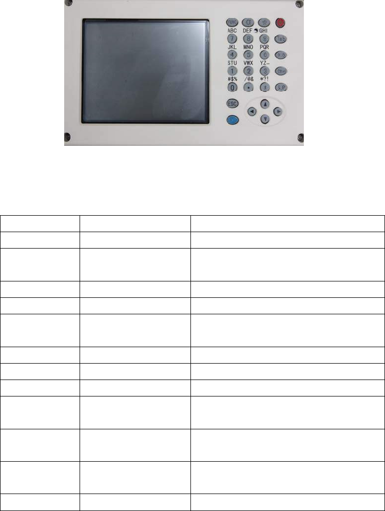
1.2 Keyboard
RTS350 series is equipped with two color touch screens and alphanumeric keypad,
operation by both touching screen and pressing keyboard is possible.
Do not touch the screen with ball-pen, pencil or other sharp thing to avoid damage on
instrument.
Keys Name Functions
0~9/ A~! Alphanumeric keypad Enter text and numerical values.
α Shift key for character
entry
The current entry method can shift among
number, smaller letter and capital letter.
★ Star key Normal configurations can be set here
Tab Tab key Move the cursor right or next position
BS BackSpace key Move the cursor left and delete one
character
Ctrl Ctrl key Same with the Ctrl key of PC
Space Space key Enter the space
Enter Enter key Confirm an entry or selection
ESC Escape key Quit a screen or edit mode without saving
changes. Return next higher level
FUNC Function key Perform variable functions defined by
program screen
◄▲▼► Navigation key Control the focus bar within the screen
and the entry bar within a field
ⓛ Power key Turn on/off the instrument
4
1.3 Main menu
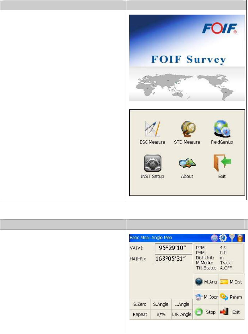
Function introduction Display
After initiating the instrument the screen will
go to present “Welcome Interface” which is
shown right. FOIF AIOSurvey consists of
several functions, that is, “BSC Measure
(Basic Measurement )”, “STD Measure
(Standard Measurement)”, “Engineering
Surveying (FieldGenius )”, “INST Setup
(Instrument Setup)” and “About(Relevant
Information)”.
FOIF AIOSurvey is applied for not only
fundamental products like instruments of
TS810 and RTS350 WINCE series total
station, Gyroscope Station but also derivative
products such as Robot Total Station, Imaging
Total Station and Network Total
Station(CAN/LAN).
1.3.1 Basic Measurement
Function introduction Display
Click “BSC Measure” key to activate basic
measuring. This function is used for simple
measuring and calculating, including angle
measurement, distance measurement,
coordinate measurement and parameter
setting. Distance measurement mode
underpins Remote Elevation Measurement
and Line-height Measurement. Coordinate
measurement mode includes Traverse
Surveying, Angle Offset Measurement,
Distance Offset Measurement, Plane Offset
5
Measurement, and Column Offset
Measurement.
Besides, basic measurement is also used for
performance testing for total station.
1.3.2 STD Measurement(Optional)
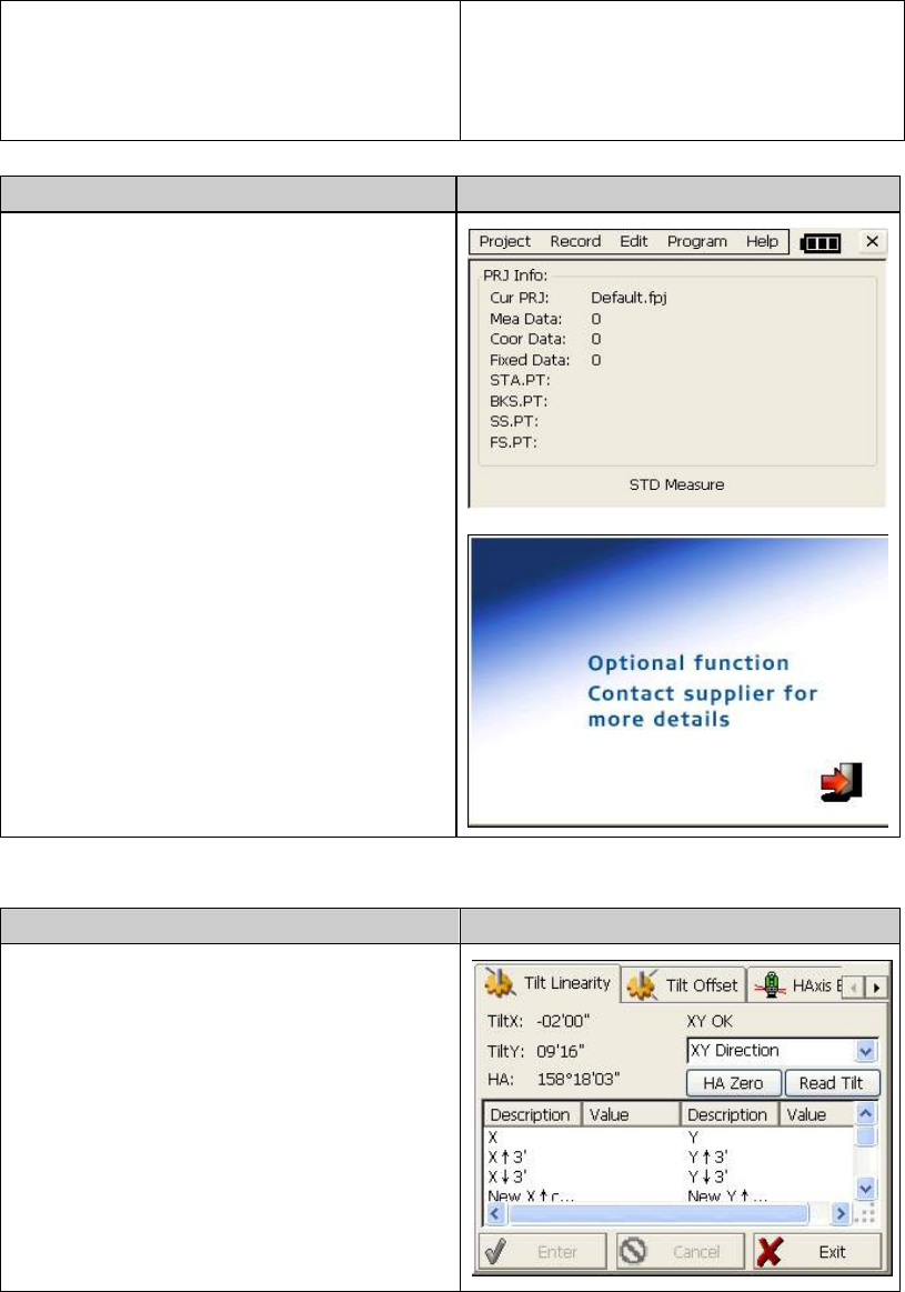
Function introduction Display
STD measurement function is used to resolve
and calculate applied measurements during
conventional surveying. It contains “project
management”, “import/export”, “instrument
station setup and orientation”, “foresight
measurement”, “backsight measurement”,
“side-looking measurement”, “cross-sectional
measurement”, “setting out of point, bunch
and alignment”, “road design”, “traverse
adjustment”, “coordinate geometry”, “ batter
board label”, “steel ruler connection survey”,
“data query and editing” and so on.
NOTE: This part is optional, it is normal to
display as right figure.
1.3.3 Instrument Setup
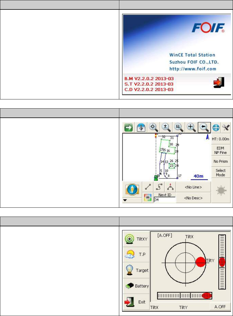
Function introduction Display
Instrument setup function is mainly applied
for instrument settings, instrument calibration
and generation and management of instrument
constant. It is made up of a series of functions
such as “compensator linear correction”,
“compensator zero correction”, “horizontal
axis error correction”, “index correction”,
“instrument settings”, “distance constant
settings”, “communication port settings”,
“configuration management”, etc.
6
1.3.4 About
Function introduction Display
The “About” function Offers information of
manufacturer and software version.
1.3.5 Professional field software
Function introduction Display
RTS350 provides professional surveying and
cartography program, such as “FOIF
FieldGenius”. In fact, FOIF RTS350 supports
more third-party softwares.
1.3.6 Convenient panel
Function introduction Display
Click 【★】 key to enter into convenient
panel. Electronic bubble function on this
panel is used for dynamic display of
electronic bubble during leveling
up.Furthermore,functions like settings of
meteorological condition, observed
object,illumination, prism constant and
communication port are provided.
7
1.4 Shortcut key
1)Some shortcut keys are applied in 350 series.
Key combination Description
⊙ Power on/off
★ Enter into setting mode directly/turn on the electronic bubble
α Shift among number, smaller letter and capital letter
FUNC+BS+⊙ Enter this combinition at the same time before starting up to
backup all settings
FUNC+CTRL+⊙ Enter this combinition at the same time before starting up to
restore all settings
FUNC+SP+⊙ Enter this combinition at the same time before starting up to
erase all settings
FUNC+BS Turn on/off backlight of key panel in face left position
FUNC+TAB Turn on/off backlight of key panel in face right position
CTRL+ESC Enter boot menu
CTRL+TAB Start touch screen calibration
FUNC+CTRL Turn on/off soft keyboards
FUNC+↑ Increase backlight brightness of LCD
FUNC+↓ Decrease backlight brightness of LCD
FUNC+← Turn on/off LCD display in face left position
FUNC+→ Turn on/off LCD display in face right position
2) method for character entry switch
Press α key, current character entry mothod will be changed, on the lower right corner, the
inputing method will display for a moment.
8
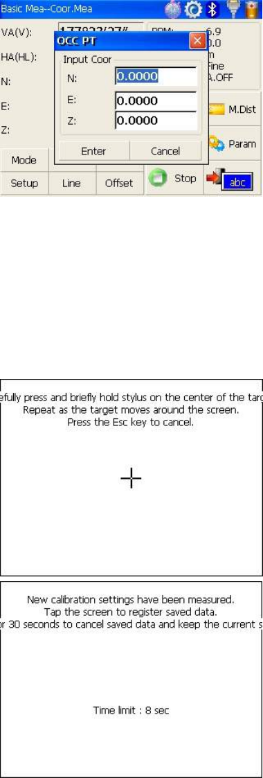
1.5 Touch screen calibration
When you operate on the screen, if your device isn’t responding to you taps, you may need to
recalibrate your screen. In any picture, press the combination key “CTRL+TAB” so as to enter
into touch screen calibration. The calibration process is shown in the figure below.
1) Carefully press and briefly hold stylus on
the center of the target. Repeat as the target
moves around the screen.
2) After all the targets are clicked, the screen
will display as left, tap the screen to register
saved data. The screen goes back to Stylus
Properties menu.
9
1.6 Battery
1.6.1 Battery Power indicator
At any screen, press【★】key to open fast
setting menu.
Select Battery, battery level will be seen
following Battery Level.
NOTE:
1. The battery’s working time will be affected by many factors, such as ambient temperature,
recharging time, recharging and discharging times. So we suggest the users recharge the
battery full or prepare several full batteries before operation.
2. The battery symbol only indicates power capability for current measurement mode. The
power consumption in distance measurement mode is more than in angle mode, if the
instrument enters into distance measurement mode from angle mode, the power maybe
auto-off because of lower battery.
3. The symbol only indicates the supply power but not the instantaneous power change. And if
the measurement mode changes, the symbol will not show the power’s decrease or increase
immediately.
4. It is suggested that user should check every battery power before field work.
10
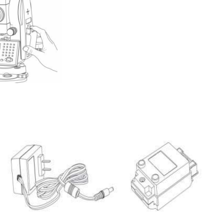
1.6.2 Replace and mount battery
1.Replace battery
1)Press the button downward as shown left.
2)Remove the battery by pulling it toward you.
2.Mount battery
1. Insert the battery to the instrument.
2. Press the top of the battery until you hear a
Click.
1.6.3 Recharge battery
1)Connect the charger connector to the battery.
2)Plug the charger on 100V/240V power supply.The red lamp becomes lighting,which
indicates recharging.If interval-time is longer,the connector isn’t fixed well.
3) That the green lamp flashes means recharging is complete.
NOTE: 1) New battery (or battery does not used for several months) should be recharged for
several times.Please recharge it more than 10 hours, and then the battery can
attain best status.
2) Please recharge the battery continuously for another 1~2 hours after the light
green,which is good for the battery.
11
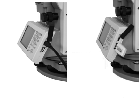
1.7 USB connection
● The file in the instrument could be read through ActiveSync software by USB cable.
● External memory stick could be used by USB Host connector. The file in the external
memory stick could be read in the instrument interface.
1)Open the cover of USB which behind the display panel;
2)Input external memory stick into USB Host connector;
3)The external memory stick could be recognized as hard disk automatically. It could be file
copy etc.
12
1.8 Guide light(Optional)
Guide light is optional in RTS350 series total station. It is mainly used to stake out. The
Surveyor could adjust the position of prism and station through the guide light color. It
will be faster to set the prism.
The guide light could be seen within 100M. The distance will be effective by atmospheric
conditions and others.
Under the face left, the Surveyor should move to left direction when he only saw the
green light or the light became bigger; If only saw the red light or red light became bigger,
the surveyor should move to the right direction.
The move direction will be contrary when the
telescope is in face right.
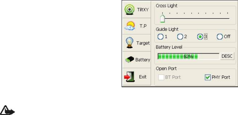
Guide light on/off: press【★】to open fast
setting menu, select Battery, if the instrument is
equipped with guide light module, 4 options for
Guide light are active, ①②③ are for adjusting
guide light intensity, select {Off} to turn off
guide light.
13
2. Preparation before Measurement
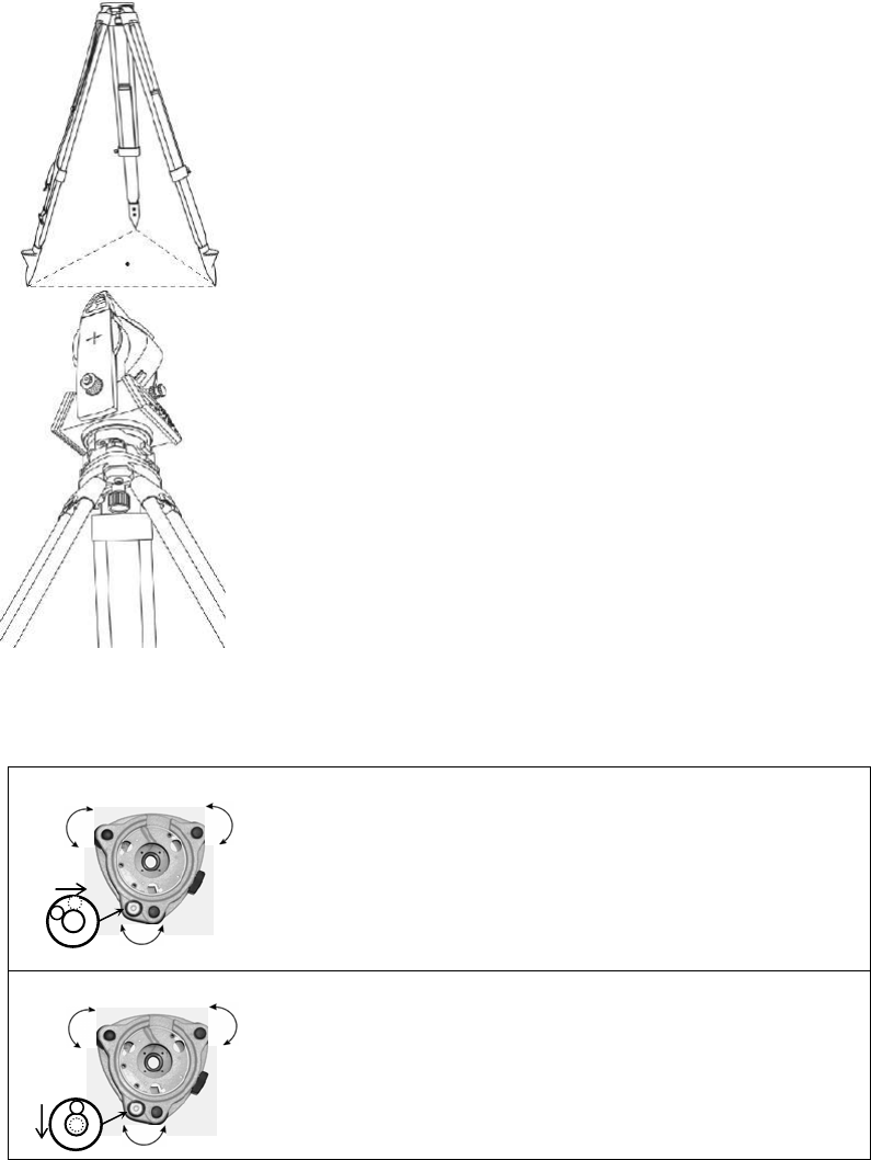
2.1 Setting up the instrument
(1) Set up the tripod first: extend the extension legs to suitable
lengths and tighten the screws on the legs.Make sure the legs are
spaced at equal intervals and the head is approximately level. Set
the tripod so that the head is positioned over the surveying point.
Make sure the tripod shoes are firmly fixed in the ground.
(2)Attaching the instrument on the tripod head: mount the
instrument carefully on the tripod head. Supporting it with one
hand, tighten the centering screw on the bottom of the unit to
make sure it is secured to the tripod.
2.2 Levelling-Up
(1) Basic Levelling-Up with the circular level
1. Move the foot screws A and B in opposite direction till
the circular bubble is perpendicular to a line shaped with
screw A and B. The direction of rotation in left thumb
indicates the movement of the circular bubble.
2. Move the bubble to the center of the circle by turning
screw C.
Screw A Screw B
Screw C
Screw A
Screw C
Screw B
14
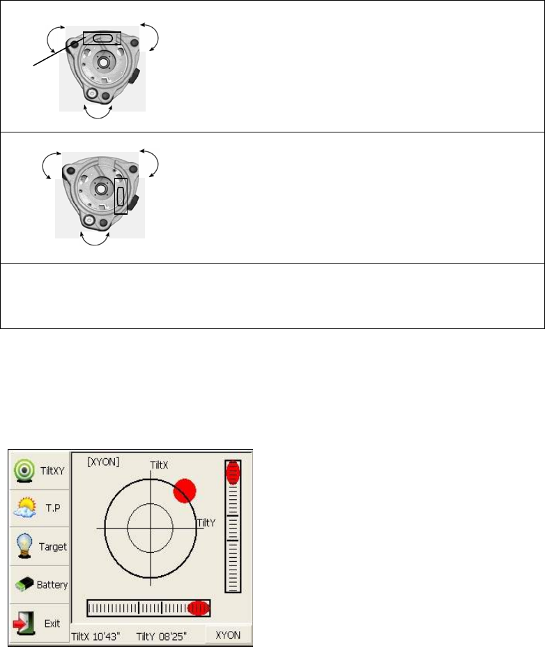
(2) Accurate Levelling-Up with plate level
1. Loosen the horizontal motion clamp, and turn the
instrument till the plate level is parallel to a line shaped
with screws A and B. Adjust the screws A and B to
make the bubble in the center of the level.
2. Loosen the horizontal motion clamp, and turn the
instrument approximately 90°.Adjust the screw C until
the bubble in the center of the level.
3. Repeat above steps until the bubble remains in the
center of the plate level while the instrument is rotated to
any position.
(3) Accurate Levelling-Up with Electronic Level on the screen
It is convenient for TS350 series to level-up with electronic level, especially when it is
difficult to observe the circular level and plate level.
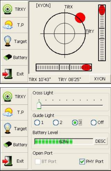
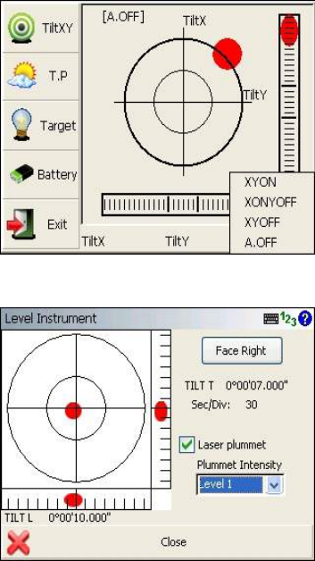
Firstly,press the key 【★】 to turn on the
electronic bubble as shown in left figure.On
the electronic bubble screen,five function
keys are displayed in the left column,which is
listed as follows:
【TiltXY 】dynamic display of electronic
bubble
【T.P】observation and setting of temperature
and atmospheric pressure
【Target】target condition of surveying
【Battery】dynamic display of battery level
【Exit】exit the electronic bubble screen
Secondly,level it by turning three foot screws and ensure the bubble is in the plate
level.Make sure the red spot is in the center.
Screw B
Screw A
Plate level
Screw C
Screw A Screw B
Screw C
15
Note:
As shown,you can realize transformation of
compensation options by pressing the lower
right button.
【XYON】compensate horizontal angle and
vertical angle at the same time
【XONYOFF】just compensate X axis
【XYOFF】don’t compensate X axis and Y
axis
【A.OFF】don’t compensate X axis and Y
axis,and turn off the popup function of electronic bubble.
In FOIF FieldGenius software, the Level
display is always shown as left figure.
16
2.3 Centering
2.3.1 Centering with Optical Plummet (Optional)
Turn the focusing ring of the optical plummet to focus the ground mark point. Then adjust
three foot-screws to center the bubble of the circular level. If the plate level is not
leveling-up, you can loosen the center screw of the tripod, and move the instrument to
center the bubble of the plate level. At last tighten the center screw.Repeat above steps
until the center of reticule always coincides with the mark point when rotating alidade of
instrument.
Note: You’d better use the three leveling screws and tripod to center the instrument.
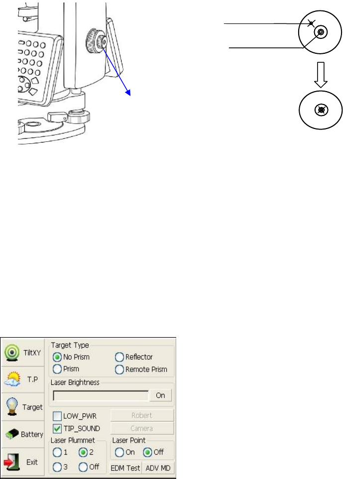
2.3.2 Centering with Laser Plummet
Press the key 【★】 to enter into the display
as shown in the left figure.
Operation Steps:
①Click the “target” button,and you can turn
on laser plummet and set it as three levels of
brightness.Thus,that laser emits downwards
can be seen.
②Loosen the center screw of tripod,and
move the base plate on tripod head until the
laser spot coincides with ground mark
point.Then tighten the center screw.
③Repeat leveling and two steps until the instrument keeps leveling and the laser spot
coincides with ground mark point when rotating alidade of instrument in any direction.
④After centering,please turn off laser plummet to save power.
Plummet
Center
Optical
plummet
Crossmark
17
3 Instrument settings
Instrument settings software is applied for settings and calibration of
instrument,generation and management of instrument constant.It is made up of a serie of
functions such as “compensator linear correction”, “compensator zero correction”,
“horizontal axis error correction”, “index correction”, “instrument settings”, “distance
constant settings”, “communication port settings”, “configuration management”,etc.
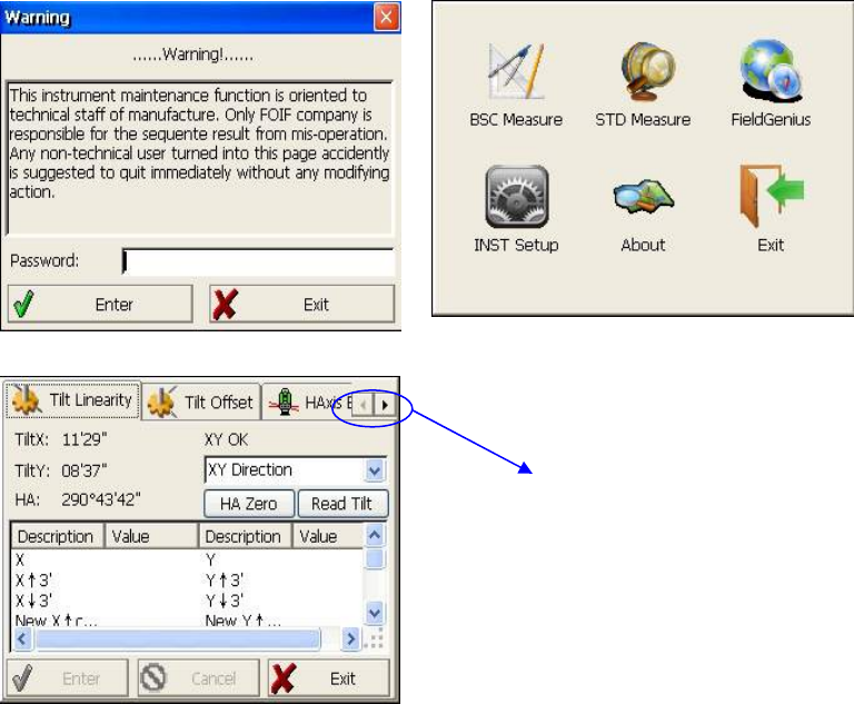
3.1 INST Setup
Enter “instrument settings” program by clicking “INST Setup” icon on the desktop.And
then input the password “12345678” to display configuration settings screen.On the
screen tap ◄ or ► keys, different setting screen can be shifted.
NOTE: This password is open for all users, current configuration settings can be
checked here, but not be adjusted. If you want to adjust these settings, please contact local
distributer or FOIF company.
Tap ◄ or ► keys to display
other settings
18
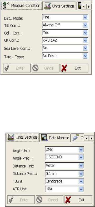
3.1.1 Setting the measure condition
Opereation:
1. The distance measurement mode will be: Fine, Coarse, Repeat Fine, Average Fine,
Tracking.
2. Tilt correction mode will be: HV, V, NO,
Always off.
3. Collimator correction mode will be: Yes or
No.
4. CR correction mode will be:
K=0.142,K=0.2, No.
5. Sea Level correction mode will be: Yes or
No.
6. Target Type mode will be: Prism, No Prism,
Reflector.You could press “Enter” to keep the
setting or press cancelled.
3.1.2 Setting the units
Operation:
1. Angle unit mode will be:DMS,GON,MIL.
2. Angle Precision mode will be: 1 second,
0.1 second or 0.5 second.
3. Distance Unit mode will be: Meter, US
Feet, Feet.
4. Distance precision mode will be: 1mm or
0.1mm.
You could press “Enter” to keep the setting
or press cancelled.
19
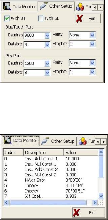
3.1.3 Setting parameters of communication ports
As left shows,click “Other Setup”,you can
activate bluetooth(BT) and
guidelight(GL),and set parameters of
“Bluetooth Port” and “Phy Port”.
3.1.4 Instrument parameters review
Click “Data Monitor” used for reviewing the setting parameters.
20
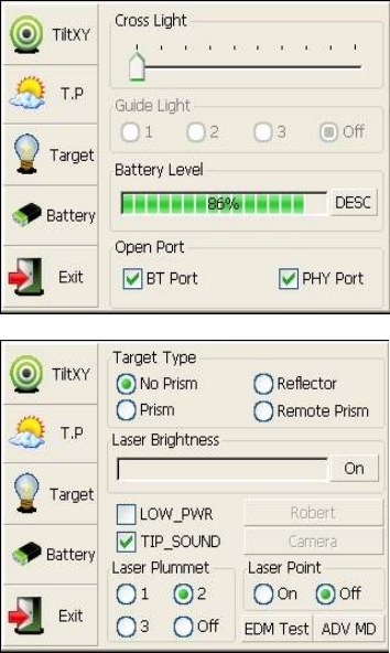
3.2 Illumination settings
Press the【★】 button and click “Target” and
“Battery” keys in order to go on with
illumination settings including “Cross Light”,
“Guide Light”,and“Laser Point”.
Cross Light: Click this item to turn on the
reticle illumination, and move the slipping
button to adjust reticle illumination.
Guide Light:Click “Battery” key,resulting in
display on which guide light could be
adjusted.
Laser Point: Tun on/off the laser flash before
distance measurement.
21
4. Basic measurement program
4.1 Run the program “Basic Measurement”
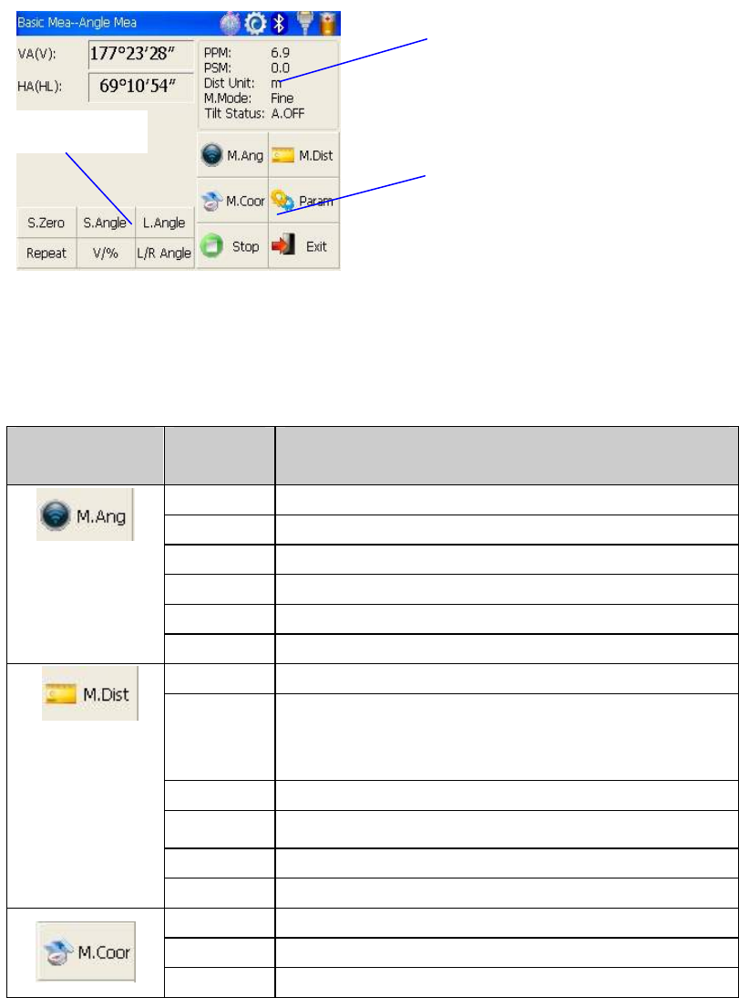
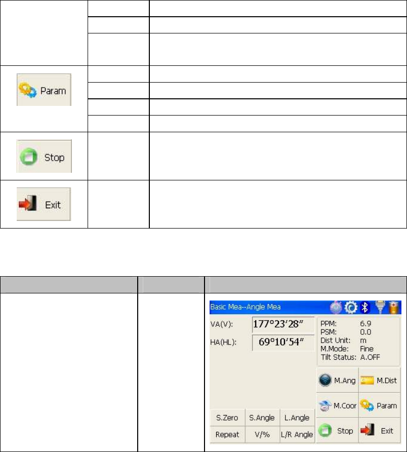
4.2 Basic measurement screen introduction
The function keys display in the lower left corner of screen,and they vary from one
measurement mode to another.There are some function keys under every measurement
mode being listed in the following table.
Measurement
mode
key function
S.Zero Set current horizontal angle as zero
S.Angle Set current horizontal angle
L.Angle Lock horizontal angle
Repeat Retest horizontal angle
V/% Switch between vertical angle and percent grade
L/R Angle Horizontal angle switch between left and right
Mode Set Fine,N Fine,Loop Fine,Track measurement mode
m/ft Switch among meter,international feet and American feet
in
terms of distance unit
Setout Set out measurement mode
REM Start REM function
MLM Start MLM function
LHM Start LHM function
Mode Set Fine,N Fine,Loop Fine,Track measurement mode
OCC PT Set the coordinate of instrument station
S.BS Set the coordinate of a backsight point
Function keys
Current parameters
Measurement mode
22
Setup Set instrument height and target height
Line Start traverse surveying
Offset Start offset measurement(ANG.Offset,DIST
Offset,PLANE Offset,CYL.Offset) function
Coor Order Set displayed coordinate order as NEZ or ENZ
Save Coor Save coordinate of instrument station or not
Ang.Unit Set Ang.Unit as DMS,GON,MIL
Dist Unit Set Dist Unit as m,UsFeet,IntFeet
Stop
Stop distance measurement
Exit
Exit basic measurement program
4.3 Angle measurement mode
4.3.1 Horizontal angle(right angle) and vertical angle measurements
At first, make sure the operation is under angle measurement mode.
Operation steps Keys Display
① Collimate the first target
A
Collimate A
23
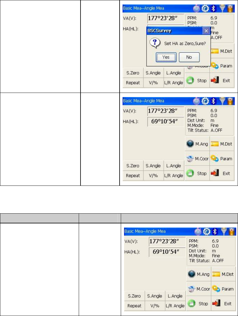
Set horizontal angle as ②
zero for target A.Click the
“S.Zero” button,and choose
“OK” in the popup dialog
box.
【S.Zero】
【OK】
Collimate the second first ③
target B,and the horizontal
angle and vertical angle will
display on the screen of
instrument.
Collimate B
4.3.2 Horizontal angle switch between right and left
Make sure the operation is under angle measurement mode.
Operation steps Keys Display
Make sure the operation is ①
under angle measurement
mode
24
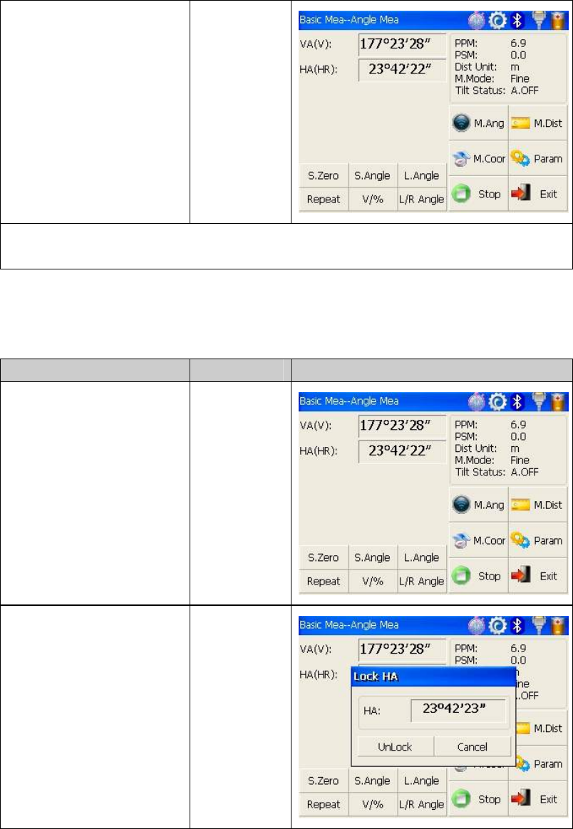
switch horizontal angle ②
between left and right by
Clicking “L/R Angle” key
※1
【L/RAngle】
※1 Left angle or right angle will be switched in turn every time you click the “L/R Angle”
key.
4.3.3 Setting horizontal angle with the “L.Angle” key
Make sure the operation is under angle measurement mode.
Operation steps Keys Display
①Turn horizontal circle unit
in the needed direction with
horizontal clamp and tangent
part.
Click “L.Angle” key,and ②
activate the function of
locking horizontal angle.
【L.Angle】
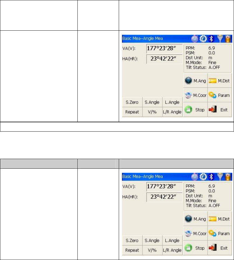
25
Collimate target point ③
used for Orientation.
1※
Click “unclock” key to ④
deactivate the function
of locking
horizontal angle.Then the
screen will return normal
angle measurement
mode,and meantime
horizontal angle will be set
as locked angle.
【Unlock】
1 Click “Cancel” key ※before it returns to Previous mode.
4.3.4 Setting horizontal angle with the “S.Angle” key
Make sure the operation is under angle measurement mode.
Operation steps Keys Display
Collimate target point ①
used for Orientation.
26
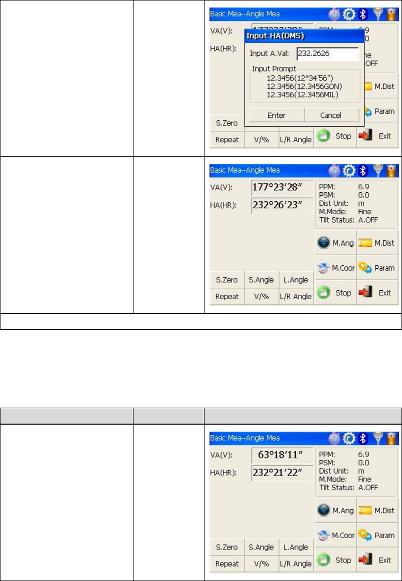
Click “S.Angle” key, and ②
a dialog box will be ejected,
as is showed in the right
figure.
Input horizontal angle you ③
need.
※ 1
Such as:232°26'26"
【S.Angle】
input
horizontal
angle
With data entry complete④,
click “Enter” key,and angle
measurement after
orientation will go on.
【Enter】
※1 Data entry should be refered to the format shown in the dialog box.
4.3.5 Setting “vertical angle and percent grade” mode with the “V/%” key
Make sure the operation is under angle measurement mode.
Operation steps Keys Display
Make sure① the operation is
under angle measurement
mode.
27
Click “V/%” key. ②
1※
【V/%】
1 Vertical angle and percent grade will be switched in turn every time you click “V/%” ※
key.
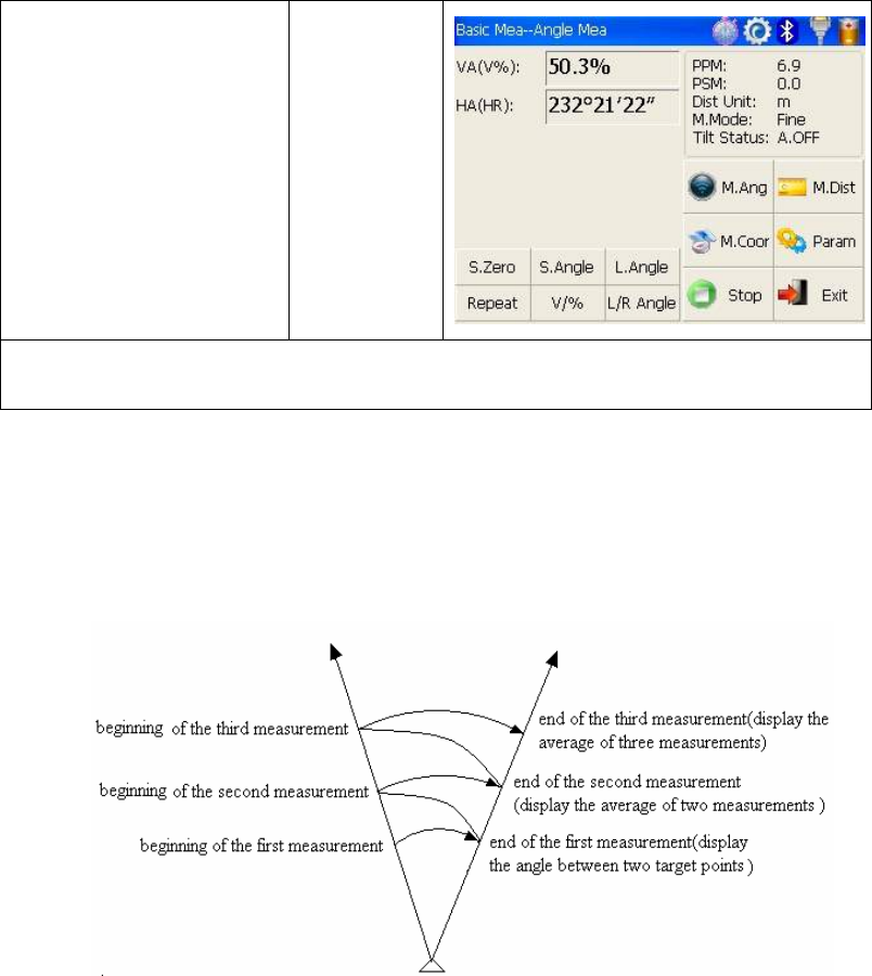
4.3.6 Carrying out angle retesting with the “Repeat” key
This program is applied for adding up angle retesting values,displaying the sum and the
average of all observed values,and meantime recording the number of observations.
28
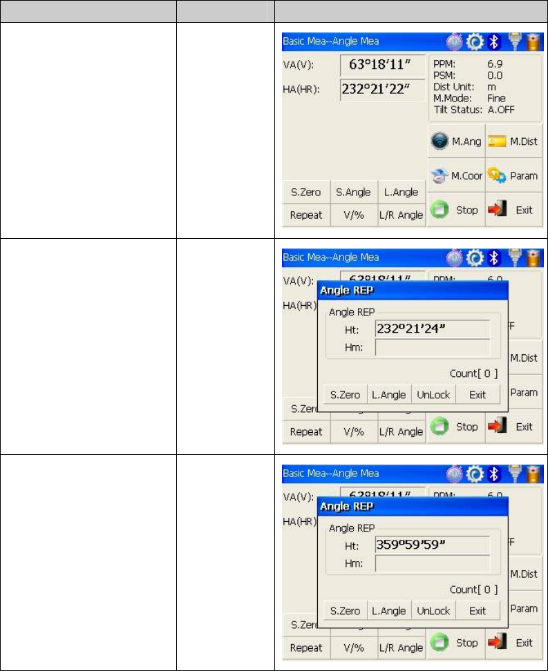
Operation steps Keys Display
①Click “Repeat” key,and
activate angle retesting
function.
【Repeat】
②Collimate the first target
A. Collimate A
③Click “S.Zero” key,and
set horizontal angle as
zero.
【S.Zero】
29
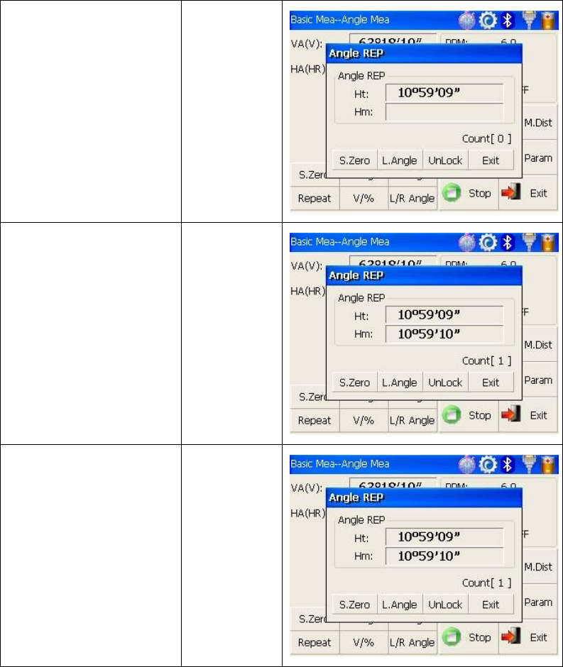
④Collimate the second
target B using horizontal
clamp and tangent part.
Collimate B
⑤Click “L.Angle” key. 【L.Angle】
⑥Collimate the first target
A again using horizontal
clamp and tangent part.
⑦Click “Unlock” key.
Collimate A
again
【Unlock】
30
⑧Collimate the second
target B again using
horizontal clamp and
tangent part.
⑨Click “L.Angle”
key.And then the screen
displays the sum and the
average of all angles.
※1
Collimate B
again
【L.Angle】
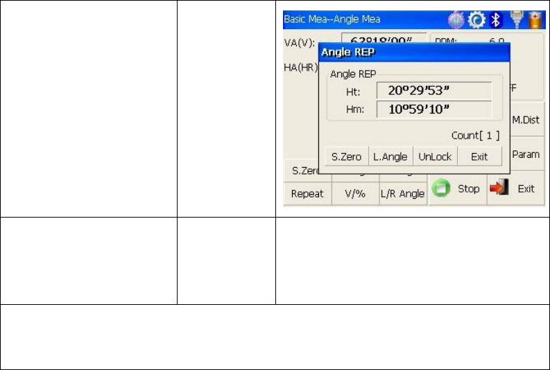
⑩Repeat steps ⑥~⑨
according to the
requirement,and carry out
angle retesting. ※2
※ 1 Click “Exit” key to finish angle retesting
※ 2 Ht:the sum of multiple observed values
Hm: the average of multiple observed values
31
4.4 Distance measurement mode
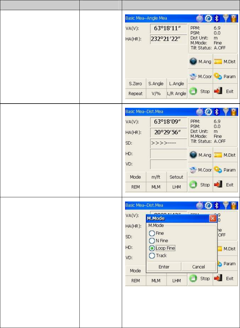
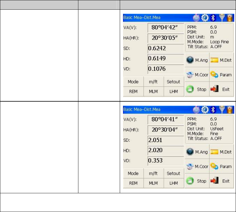
4.4.1 Distance measurement and measuring mode setting
Operation steps Keys Display
Collimate the ce①ntre of
prism.
Collimate
Click “M.Dist” key to ②
enter distance measurement
mode, and then the system
will carry out measurement
based on previous setting
mode.
【M.Dist】
Click “③Mode” key to
activate setting function
of distance measurement
mode. Take “Loop Fine” as
example here.
Fine: single fine measuring
mode
N Fine: n times fine
measuring mode
Loop Fine: Continuous
measuring mode
Track: tracking measuring
mode
【Mode】
32
Display the result of ④
measurement.
1※~2※
※ 1 Click “mode” key if you wanna change measurement mode,as step shows.③
※ 2 Click “M.Ang” key to return angle measurement mode.
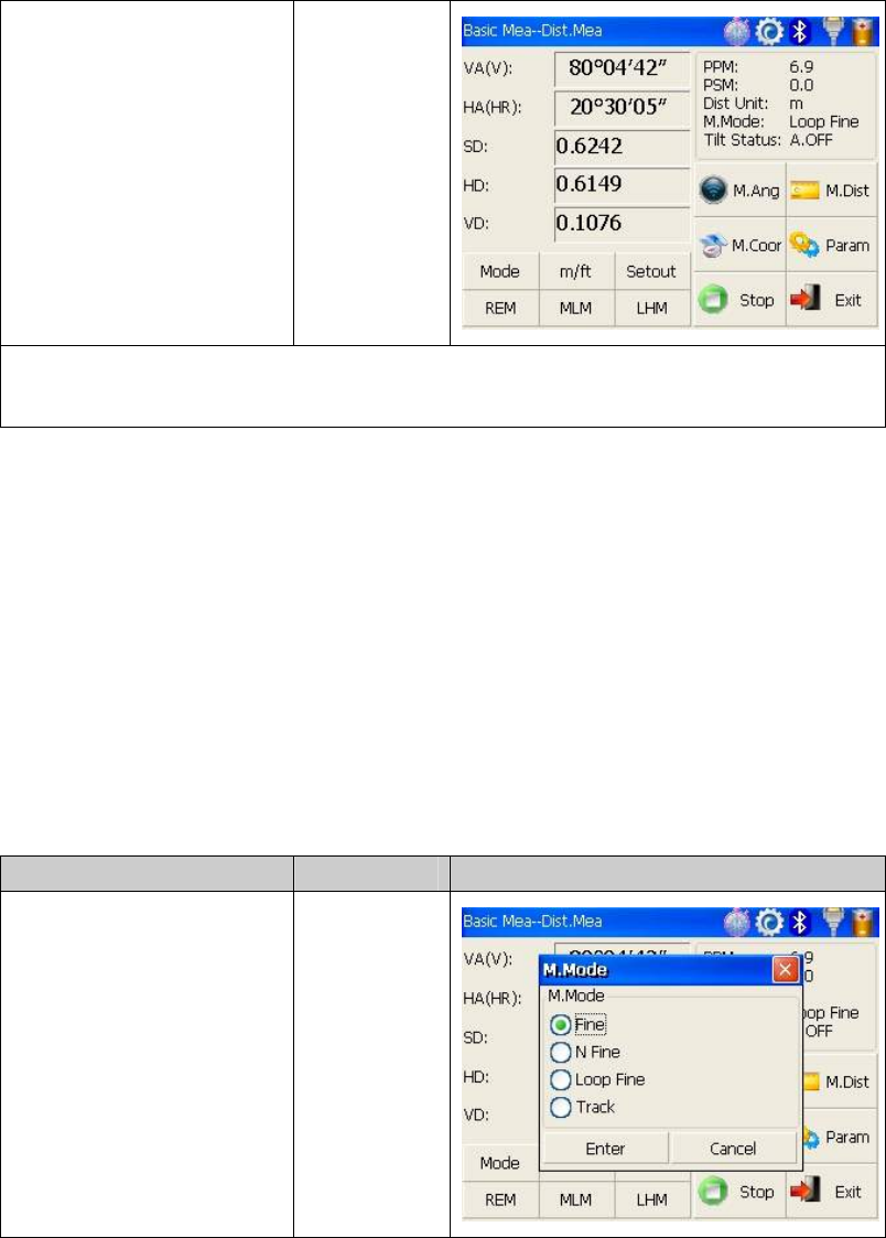
4.4.2 Fine/Tracking distance measurement
When you preset the measuring times, the instrument will carry out distance measurement
and display the average distance according to the setting times. If you preset single
observation, the average distance won’t be displayed. In general, the factory default is set
as single observation.
Operation steps Keys Display
Under distance ①
measurement mode,click
“Mode” key to activate
setting function of
distance measurement mode.
The default setting is “single
observation”.
【Mode】
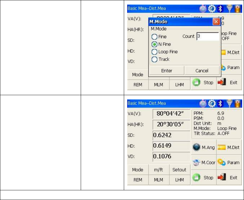
33
Click “N Fine” key with ②
stylus,and then input the
number of needed
observations in the upper
right column of screen.
【N Fine】
input the
number of
observations
Click “Enter” key,③
collimate the centre of
prism,and then the system
will carry out measurement
based on previous setting.
1※
1 Click “M.Ang” key to return angle measurement mode※.
34
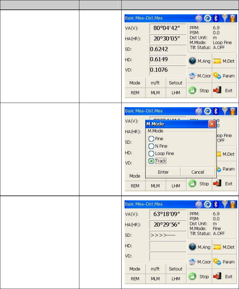
4.4.3 Accurate Measurement and Track mode
Accurate Measurement mode:it’s a normal measurement mode.
Track mode:Track mode takes less time than accurate measurement.It is mainly applied
for setting-out survey and useful for tracking moving target.
Operation steps Keys Display
Collimate the centre of ①
prism.
Collimate
prism
Clic②k “Mode” key to
activate setting function
of distance measurement
mode.And this mode is set
as “Track”.
【Mode】
Click “Enter” ③
key,collimate the centre of
prism,and the system will
carry out measurement
based on previous setting.
【Enter】
35
4.4.4 Exchange of distance units
Change distance unit on the screen of distance observation.
Operation steps Keys Display
Click “m/ft” key.① 【m/ft】
Changed distance unit ②
will display in the upper
right corner. ※1
※1 Distance unit will be exchanged among meter,american feet and international feet every
time you click “m/ft” key.
4.4.5 Distance stake out measurement
This function can display the difference between measured distance and preset distance.
Displayed Value=Observed Value – Standard(Preset) Distance
Setting out among all sorts of distance measurement modes(such as slope distance,
horizontal distance and elevation difference) can be carried on.
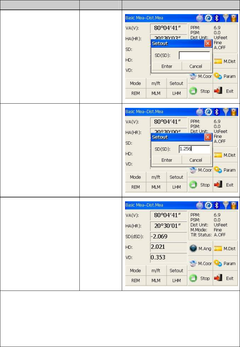
36
Operation steps Keys Display
Click “①Setout” key under
distance measurement mode.
【Setout】
Select distance ②
measurement mode
(SD,HD,VD)to be set out,
input required data and then
click “Enter” key. ※1
③Start setting out.
※1 First of all,a prompt that reminds you to input SD to be set out is displayed in the popup
dialog box. Click “Enter” key to execute SD setting out after inputing data。If you want HD
setting out,need to input zero in “SD dialog box”, click “Enter”,and the system will eject
“HD dialog box” automatically. HD setting out can go on after HD data entry. If you want
VD setting out,need to input zero in both “SD dialog box” and “HD dialog box”, thus the
system will remind you to input elevation difference to be set out.
37
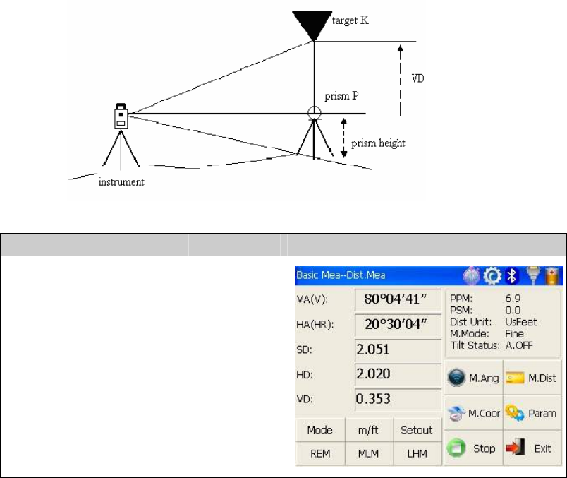
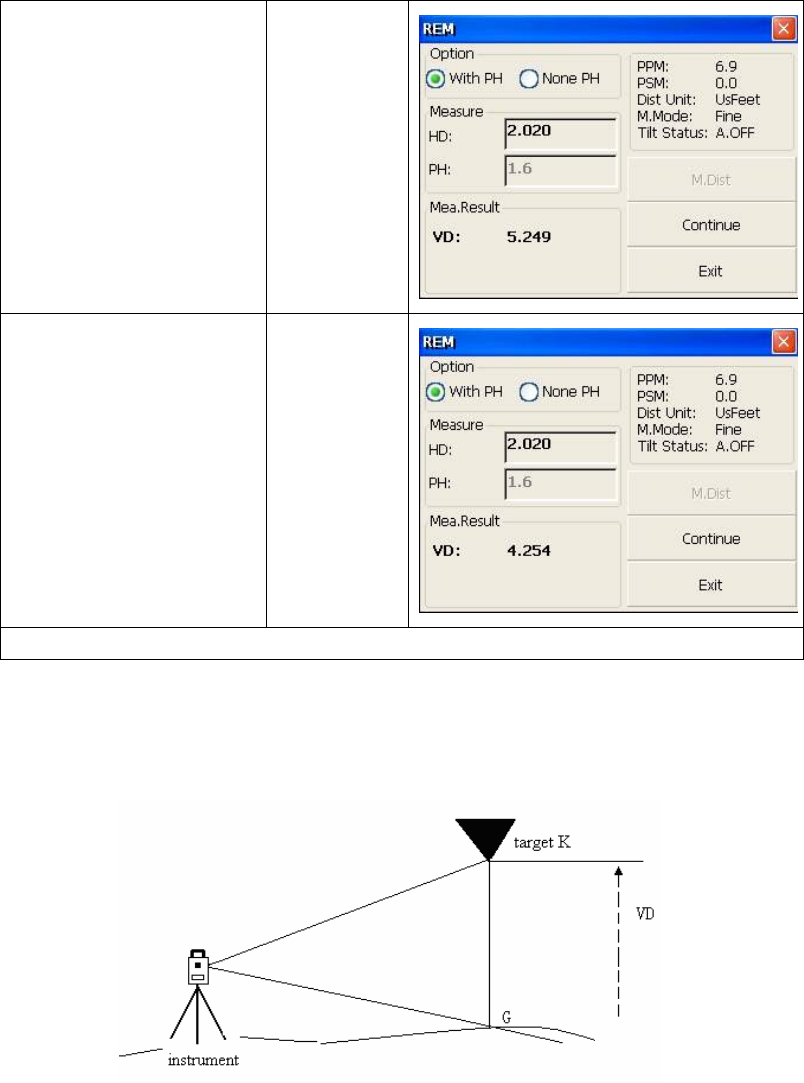
4.4.6 Remote Elevation Measurement(REM)
The Remote Elevation program calculates the vertical distance (VD) of a remote object
relative to ground. When using a prism height, the remote elevation measurement will
start from the prism (reference point). If no prism height is used, the remote elevation will
start from any reference point in which the vertical angle is established. In both modes,
the reference point should be perpendicular to the remote object.
1) With prism height (PH) input
Operation steps Keys Display
Under distance ①
measurement mode, click
“REM” key to activate
remote elevation
measurement.
【REM】
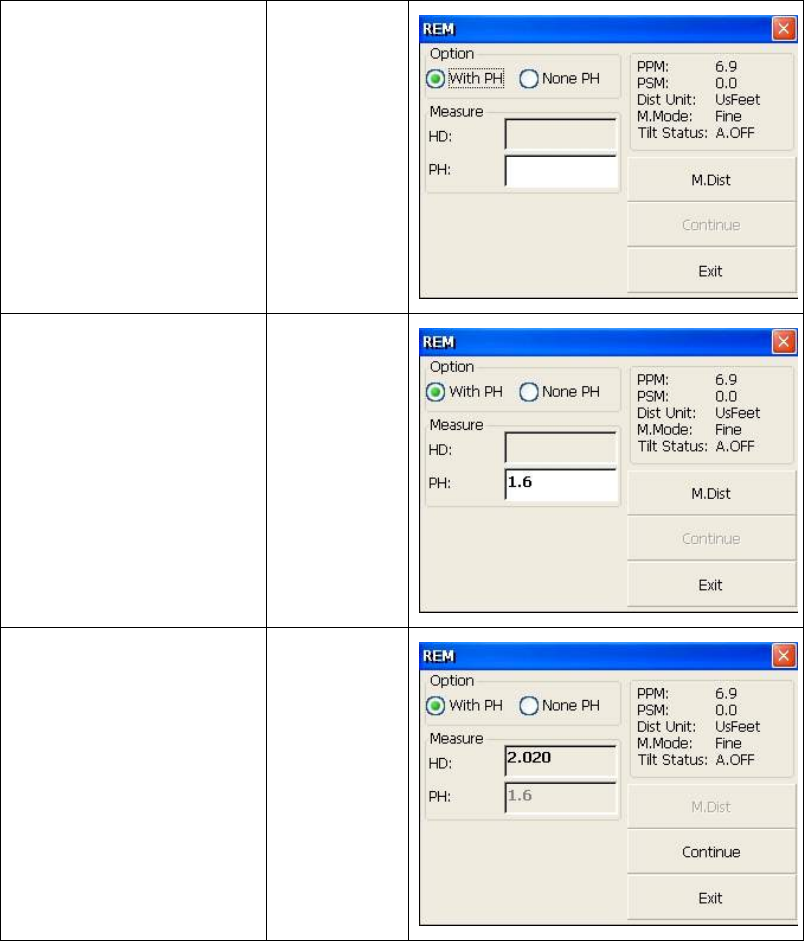
38
②Select “with PH” button
with stylus.
【with PH】
③Input the prism height
following PH.
Input prism
height
④Collimate the centre P of
prism.
⑤Click “M.Dist” key to
start measuring.
⑥Horizontal distance
between instrument and
prism will be shown.
Collimate
prism
【M.Dist】
39
⑦Click “Continue” key, and
position of prism is locked,
that means reference point is
confirmed.
【Continue】
⑧Collimate target K and
click “Continue”, vertical
distance (VD) will be
shown.
※1)
【Collimate
K】
※1)Click “Exit” key to finish REM.
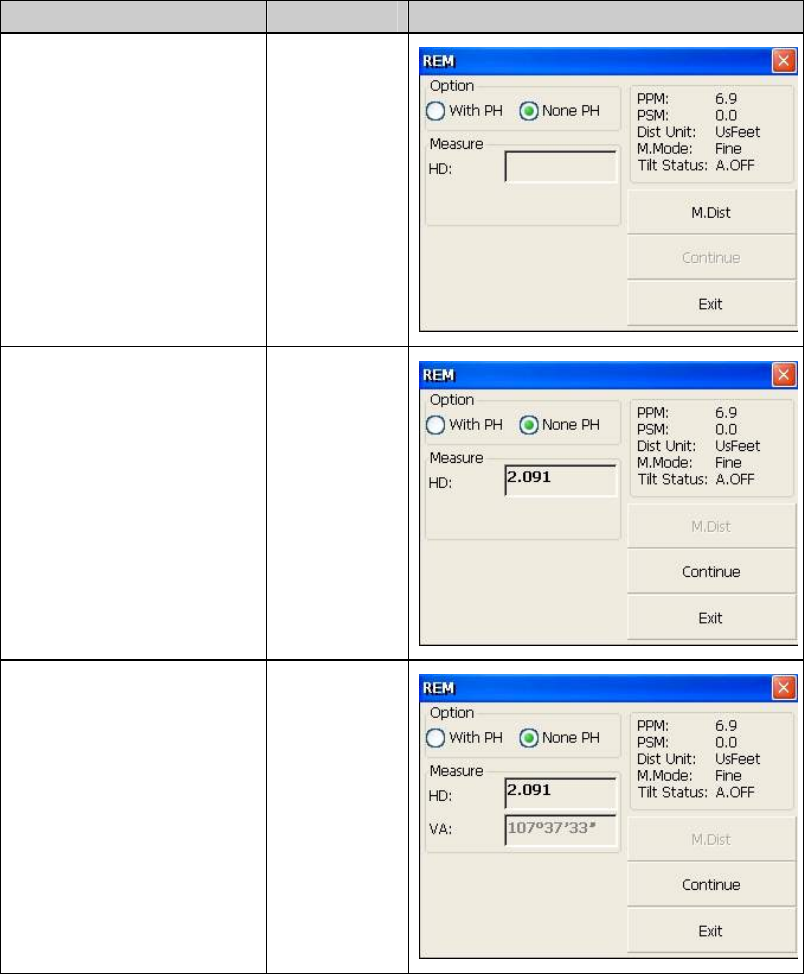
2)without prism height input
40
Operation steps Keys Display
①Select “None PH” button
with stylus.
【None PH】
②Collimate the ground
point.
③Click “M.Dist” key to
start observing.
④Horizontal distance
between instrument and
prism will be shown.
Collimate
prism
【M.Dist】
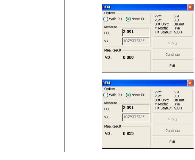
⑤Click “Continue” key, and
position of ground point G is
locked that means reference
point is confirmed.
【Continue】
41
⑥Click “Continue” key. 【Continue】
Collimate ⑦remote target
K.Vertical distance(VD) will
be shown.
1)※
Collimate
target
1) Click “Exit” to finish REM.※