SUZHOU FOIF RTS352 Total Station User Manual 2
SUZHOU FOIF CO.,LTD Total Station Users Manual 2
Contents
- 1. Users Manual 1
- 2. Users Manual 2
Users Manual 2
42
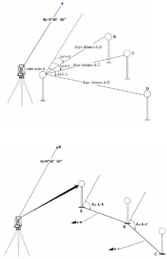
4.4.7 Missing Line Measurement (MLM)
The Missing Line Measurement program calculates the horizontal distance (dHD), slope
distance (dSD) and elevation (dVD) between two target prisms.
The instruemt can accomplish this in two ways:
1.MLM Method (A-B, A-C): Measurement is A-B, A-C, A-D, .........
2.MLM Method (A-B, B-C): Measurement is A-B, B-C, C-D, .........
43
Operation steps Keys Display
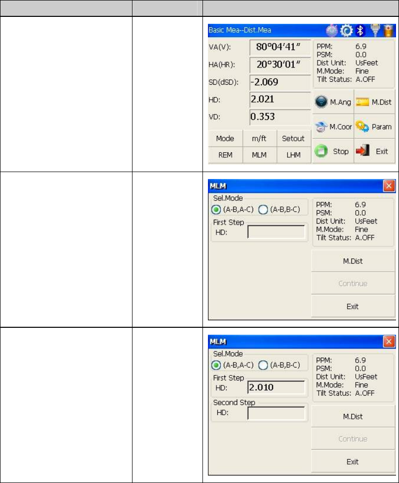
Under distance ①
measurement, click “MLM”
key to activate Missing Line
Measurement.
【MLM】
Select method (A②-B, A-C)
with stylus.
Collimate prism A,click ③
“M.Dist” key. Horizontal
distance between instrument
and prism A will be shown.
【M.Dist】
44
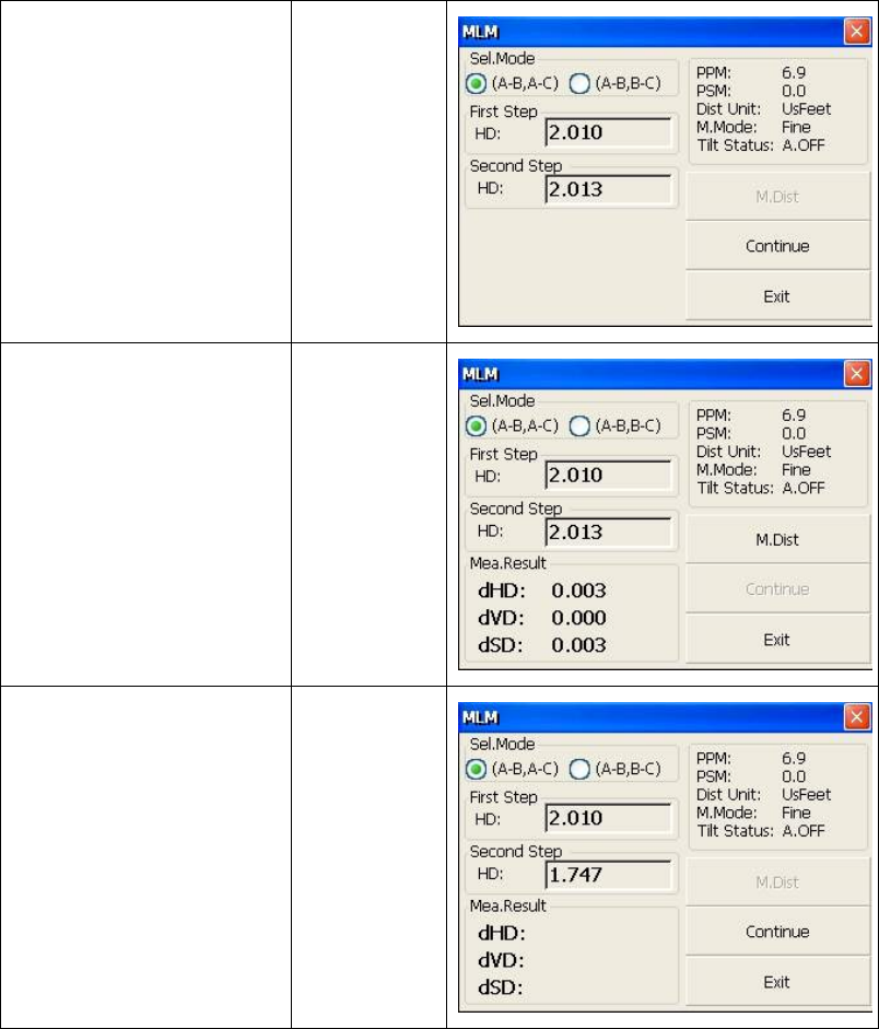
Collimate prism B,click ④
“M.Dist” key. 【M.Dist】
Click “⑤Continue” key,then
horizontal distance(dHD),
elevation difference(dVD)
and slope distance (dSD)
between prism A and prism
B will display. 1※)
【Continue】
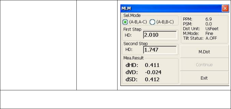
In order ⑥to calculate the
horizontal distance between
points A and C,collimate
prism C,and click “M.Dist”
key again.Thus horizontal
distance between instrument
and prism C will be shown..
【M.Dist】
45
Click “⑦Continue” key,then
dHD, dVD and dSD
between prism A and prism
C will be shown.
【Continue】
1※)Click “Exit” key to return main menu.
●Procedure of MLM Method (A-B, B-C) is completely same as Method (A-B, A-C)
Method.
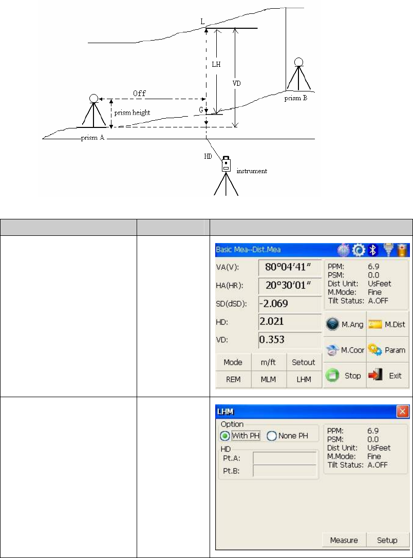
4.4.8 Line-height Measurement
This function is applied for measuring and determining a height of line(like electric
wire)above ground which is hard to reach.
See following image, L is point on the overhead line, G is projective point on the ground,
which is also difficult to set target, A and B are baseline which are set up in a certain
distance under line. After measuring horizontal distances from instrument to prisms A/B
and confirm the base line, VD between A and B, VD between L and G, HD between
instrument and L(G),offset distance from A to L(G) will be determined and shown.
46
Operation steps Keys Display
Under distance ①
measurement mode, click
“LHM” key to activate
line-height measurement
program.
【LHM】
Select “With PH” button ②
with stylus. With PH
47
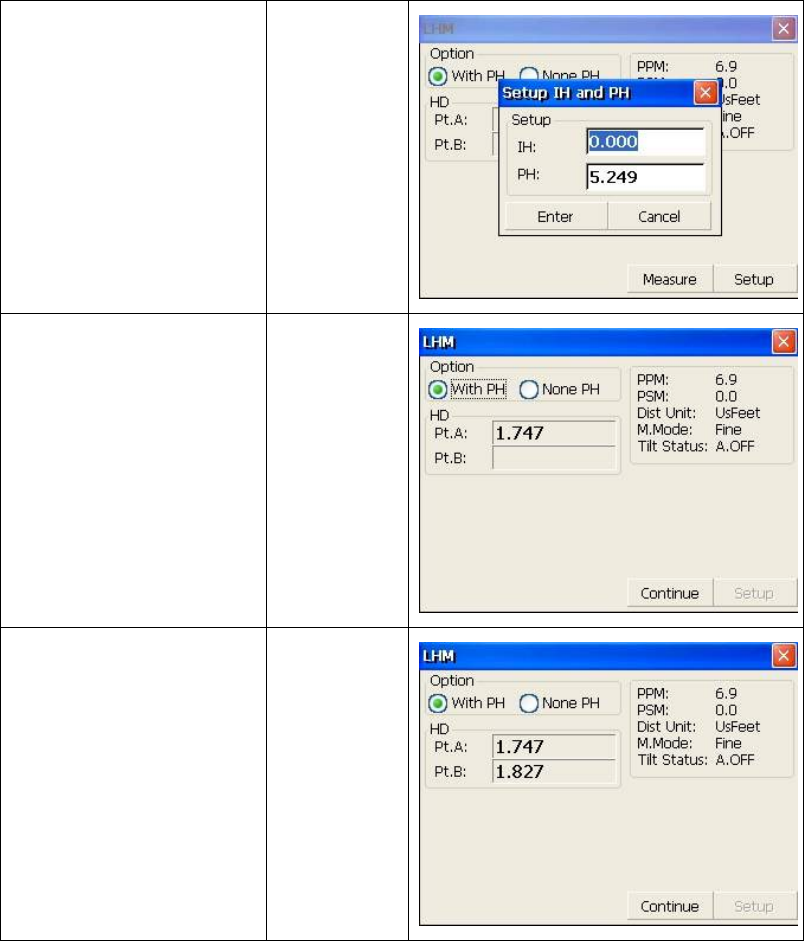
Click “③Setup” key to input
instrument height(IH) and
prism height(PH).After that
click “Enter” key.
【Setup】
Collimate prism A,④ click
“Measure” key, and distance
measurement begins. After
that click “Continue” key.
【Measure】
Collimate prism B,⑤ click
“Measure” key, and distance
measurement begins.
【Measure】
48
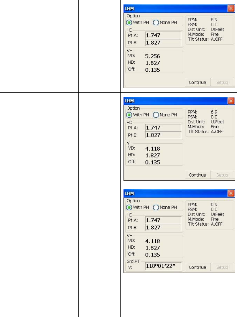
After measure⑥ment click
“Continue” key. 【Continue】
⑦Collimate point L on
overhead line. The screen
displays measuring data of
collimating L.
VD :Vertical distance
between A and L.
HD :Horizontal distance
between instrument and L.
Off :Horizontal distance
between A and L.
⑧Click “Continue” key
which is used for measuring
height between overhead
line and ground. Operation
steps:
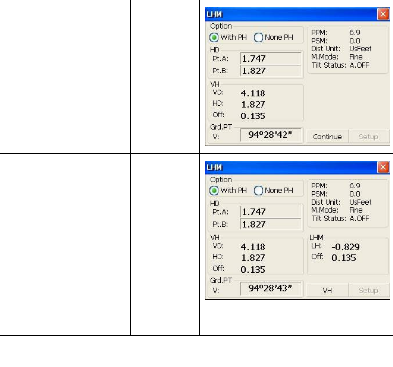
●Collimate point on
overhead line before
clicking “Continue” key.
● Lock instrument on hori
zontal direction, move tele
scope on vertical direction
until aim at ground point
G.
【Continue】
49
⑨Collimate ground point G
by screwing vertical tangent
part.
Collimate G
⑩Click “Continue” key
again, and then height of
overhead line(LH) and
horizontal distance(Off) will
display. 1)※~3)※
【Continue】
1)※ Click “X” key to end measurement.
2)※ Click “VH” key to return operation step⑦.
50
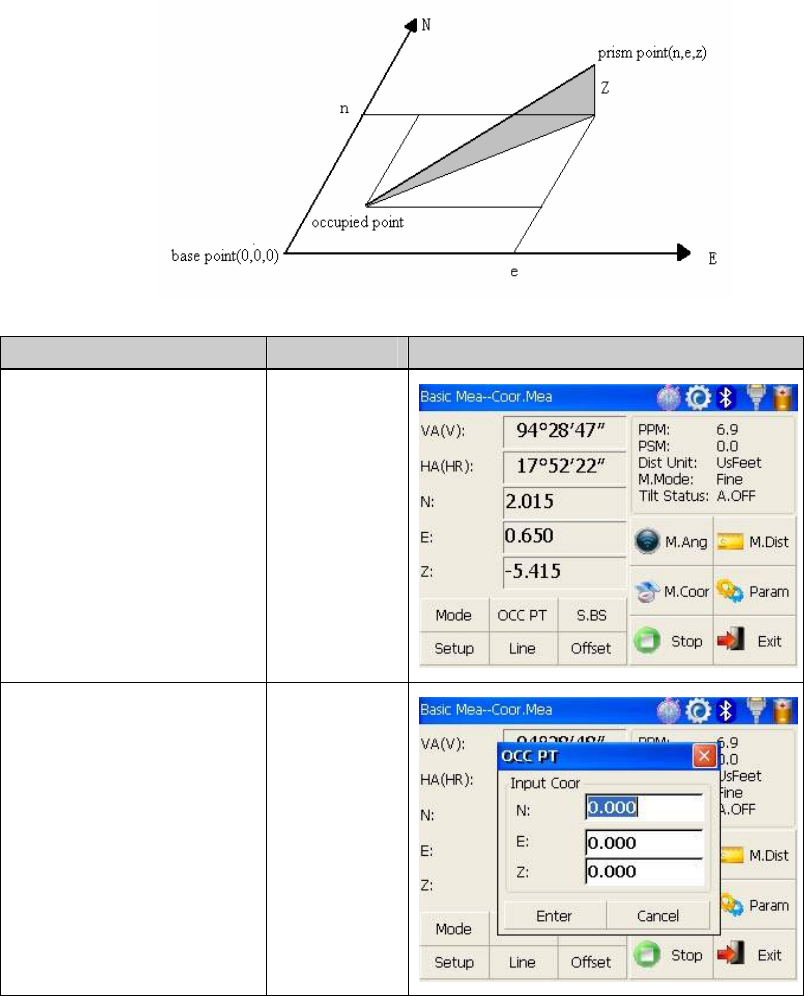
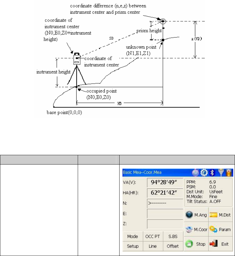
4.5 Coordinate Measurement Mode
4.5.1 Setting coordinate of occupied point
After input coordinate of occupied point(instrument location), unknown point coordinate
will be measured and displayed with this program.
Operation steps Keys Display
Click “M.①Coor” key to
enter coordinate
measurement mode.
【M.Coor】
Click “OCC PT” key.② 【OCC PT】
51
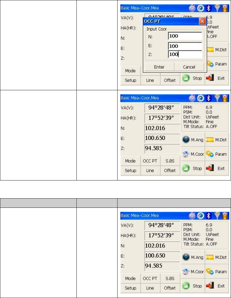
Input coordinate of ③
occupied point from N to Z.
Fini④shing data entry,click
“Enter” key and return
coordinate measurement
interface.
【Enter】
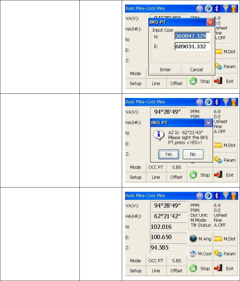
4.5.2 Setting backsight point
Operation steps Keys Display
Click “S.BS” key to set ①
backsight point. 【S.BS】
52
Input coordinate of ②
backsight point and click
“Enter” key.
【Enter】
A dialog box is ejected as ③
figure shows.
Collimate backsight point,④
click “Yes” key. And then
the system will define
backsight azimuth angle
which displays in the upper
left corner of coordinate
measurement screen.
【Yes】
53
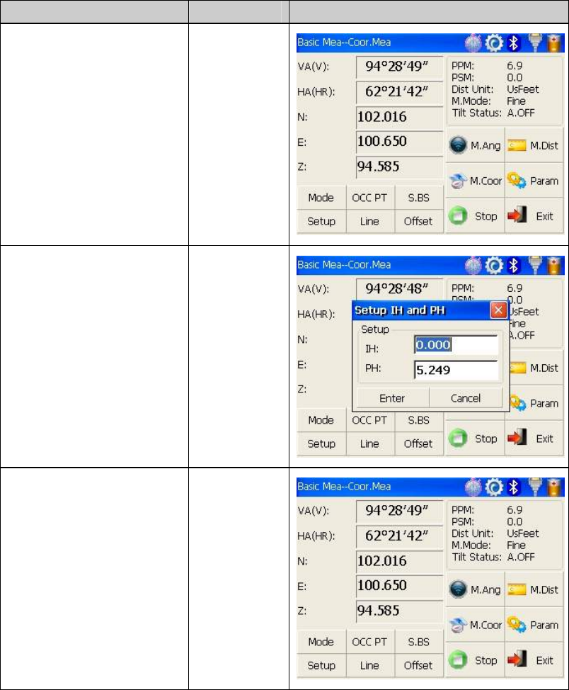
4.5.3 Setting instrument height and prism height
Coordinate measurement must be based on instrument height and prism height, thus
coordinate of unknown point can be calculated easily and directly.
Operation steps Keys Display
Click “Setup” key.① 【Setup】
Input instrument height ②
(IH)and prism height(PH).
Input IH and
PH
Finishing data entry,③ click
“Enter” key to return
coordinate measurement
screen.
【Enter】
54
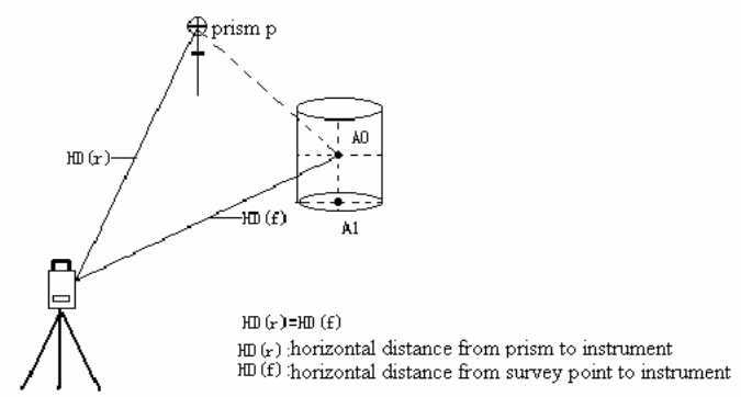
4.5.4 Operation of coordinate measurement
With coordinate of occupied point, backsight azimuth angle, Instrument height and prism
height set up,you can directly calculate coordinate of unknown point.
Operation steps Keys Display
Set coordinate of ①
occupied point and
instrument height/prism
height. 1)※
Set backsight azimuth ②
angle. 2)※
③Collimate target. 3)※
55
Click “M.Coor” key to ④
finish operation.
4)※
【M.Coor】
1)If don’t input coordinate of occupied point,※ previous coordinate of occupied point is set
as default. If don’t input instrument height and prism height, the previous is set as default
too.
※2)refer to “4.3.4 Setting horizontal angle with the S.Angle key” or “4.5.2 Setting
backsight point”。
3)Click “Mode” key to change distance measurement method(Fine/N Fine/Loop ※
Fine/Track)
4) Click “M.Angle” or “M.Dist” to re※turn normal angle or distance measurement mode.
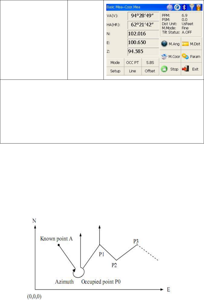
4.5.5 Traverse Surveying
Measure the coordinate of foresight point and save it in the list, this point would be taken
as the occupied point after transferring to point 2, and the previous occupied point will be
taken as the backsight point, the azimuth angle will be calculated and set.
56
z Set coordinate of occupied point p0 and azimuth angle from point P0 to known point
A.
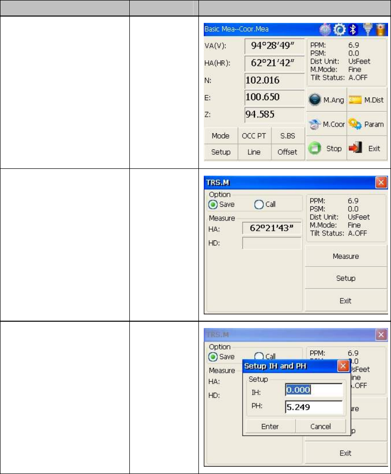
Operation steps Keys Display
Click “Line” key.① 【Line】
Click “Save” key w②ith
stylus. 【Save】
Click “Setup” key to reset ③
instrument height and prism
height. And then click
“Enter” key.
【Setup】
57
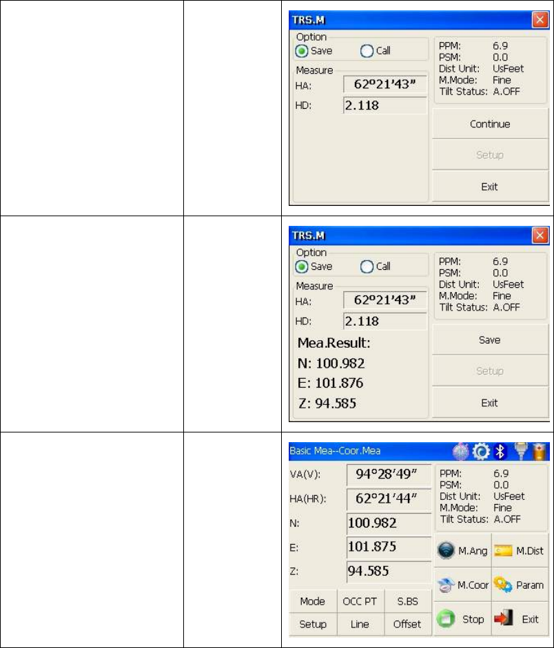
④Collimate prism in target
point P1 where instrument
will be transferred.
Meantime click “Measure”
key.
【Measure】
Click “Co⑤ntinue” key and
coordinate of Point P1
displays in the lower left
corner of screen.
【Continue】
Click “Save” key.⑥
Coordinate of P1 can be
ascertained and it will return
main menu.At last power off
and transfer instrument to
P1(transfer prism from P1 to
P0 meantime).
【Save】
58
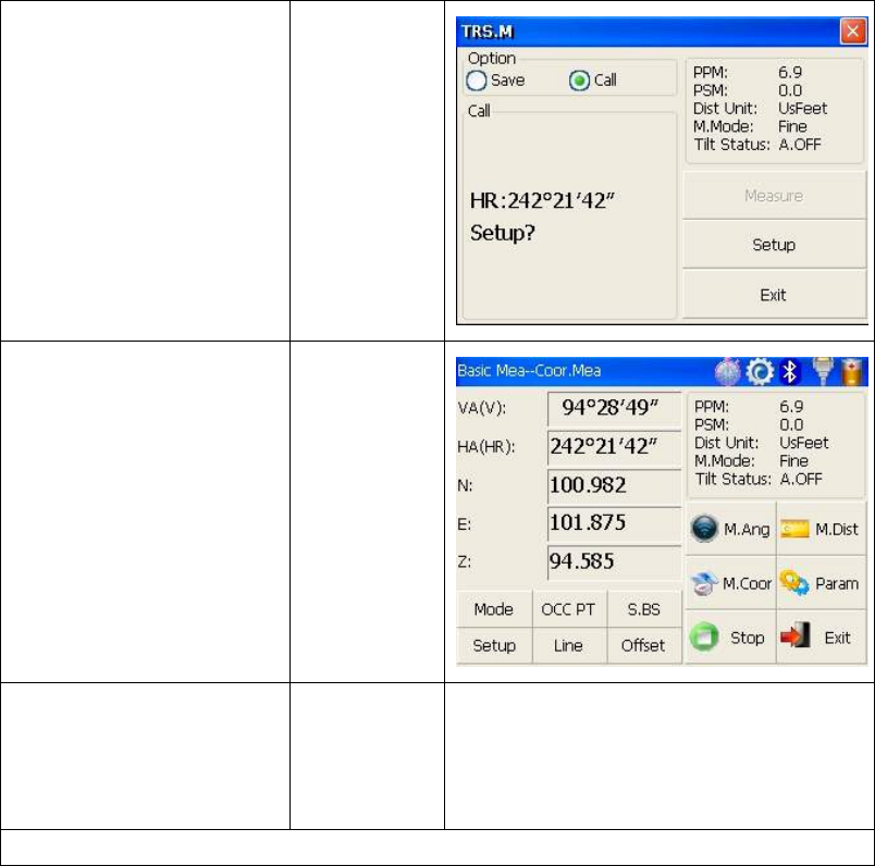
After instrument is ⑦
established in P1,enter into
traverse surveying of
coordinate measurement and
select “Call” button with
stylus.
1)※
Collimate last occupied ⑧
point P0. Click “Setup” key,
then coordinate of P1 and
azimuth angle from P1 to P0
will be ascertained. And it
returns to main menu at the
same time.
Repeat steps⑨①~⑧,and
carry on according to the
sequence of guidelines till
the end.
※1) Click “Exit” key to finish Traverse Surveying.
4.5.6 Offset Measurement Mode
There are four kinds of Offset Measurement Modes:
z Angle Offset Measurement
z Distance Offset Measurement
z Plane Offset Measurement
z Column Offset Measurement
1) Angle Offset Measurement
This program is used to measure the point where it’s difficult to set prism. Place the prism
at the same horizontal distance from the instrument as that of point A0 to measure.
59
●When measuring coordinate of ground point A1(projection of point A0),set instrument
height and prism height.
●When measuring coordinate of point A0,set instrument height only(Prism height is set as
0).
●Under angle offset measurement mode,there are two methods to set vertical angle:
1.Free vertical angle: vertical angle ranges from up-and-down movement of telescope.
2.Lock vertical angle:vertical angle is locked and can’t range from up-and-down
movement of telescope.
Thus,if collimate A0 with the first method, vertical angle ranges from up-and-down
movement of telescope,and meantime slope distance(SD) and elevation difference(VD)
will change too.But if collimate A0 with the second method,vertical angle is locked in the
direction where prism is located and can’t range from up-and-down movement of
telescope.

60
Operation steps Keys Display
① Click “Offset” key. 【Offset】
② Click “ANG.Offset” key
in ejecting dialog box.
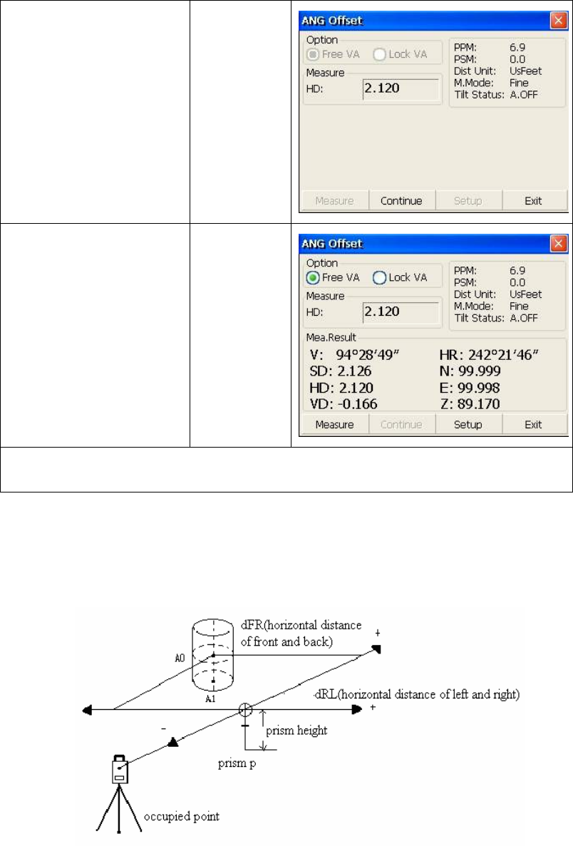
③ Select “Free VA”(or
“Lock VA”) with stylus
to to start angle offset
measurement.(User
makes a choice on the
basis of own demand)
④ Collimate prism P,and
click “Measure” key.
Collimate
prism P
61
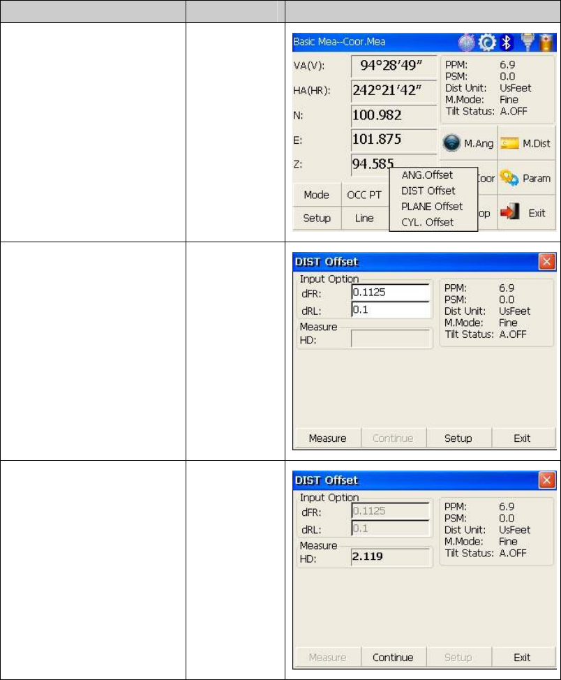
Collimate target A0 with ⑤
horizontal clamp and tangent
part.
Collimate A0
⑤ Click “Continue”
key.Then slope
distance,horizontal
distance and elevation
difference from
instrument to A0 and
coordinate of A0 will be
shown.
1)※,2)※
【Continue】
1) Click “Setup” key to set instrument heigh※t and prism height.
※2)Click “Exit” to finish Angle Offset Measurement
●Set instrument height/prism height before Offset Measurement.
●Refer to “4.5.1” to set coordinate of occupied point.
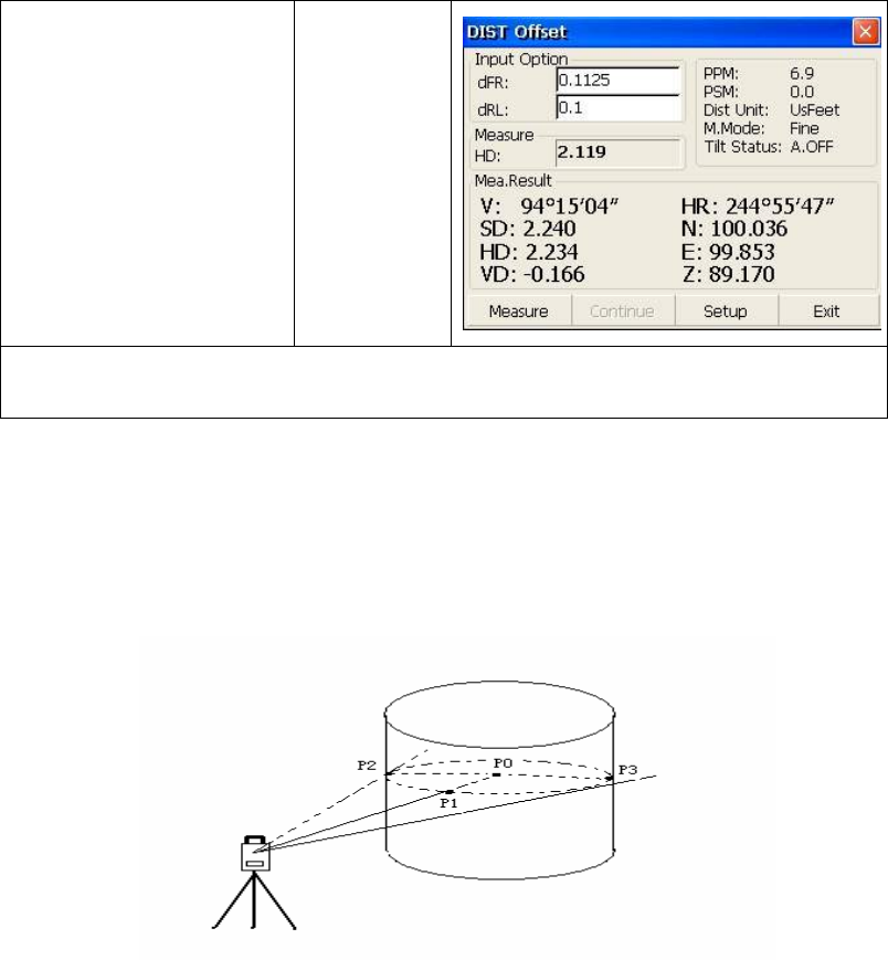
2) Distance Offset Measurement
The measurement of a target point apart from a prism is possible by inputting offset
horizontal distance of front and back/left and right.
62
●When measuring coordinate of ground point A1,set instrument height and prism height.
●When measuring coordinate of point A0,set instrument height only(Prism height is set as
0).
●Refer to “4.5.1” to set coordinate of occupied point.
Operation steps Keys Display
①
Click “DIST Offset” key in
ejecting dialog box.
【DIST
Offset】
Finish data entry with ②
stylus.
Collimate prism and click ③
“Measure” key. 【Measure】
63
Click “Continue” key,and ④
result displays with the
correction of offset distance.
1)※,2)※
【Continue】
1) Click “Setup” key to set instrument height and prism height.※
2) Click “Exit” ※key to finish Distance offset measurement.
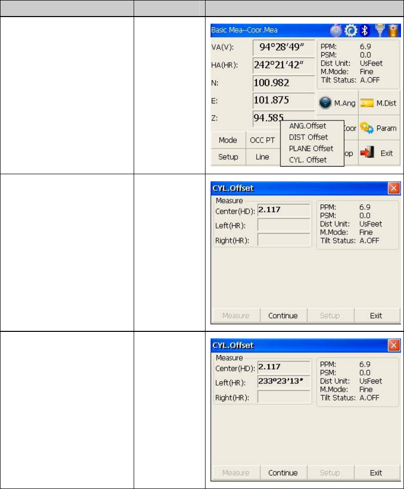
3) Column Offset Measurement
It is possible to measure circumscription point(P1) of column directly,the distance to the
center of column(P0),coordinate and direction angle can be calculated by measured
circumscription points P2 and p3.The direction angle of the center of column is 1/2 of
total direction angle of circumscription points P2 and P3.
● Refer to “4.5.1” to set coordinate of occupied point.
64
Operation steps Keys Display
①
Click “CYL.Offset” key.
【CYL.Offse
t】
Collimate the center(P1) ②
of column surface,and then
click “Measure” key.
【Measure】
Collimate left point(P2) of ③
column surface,and then
click “Continue” key.
【Continue】
65
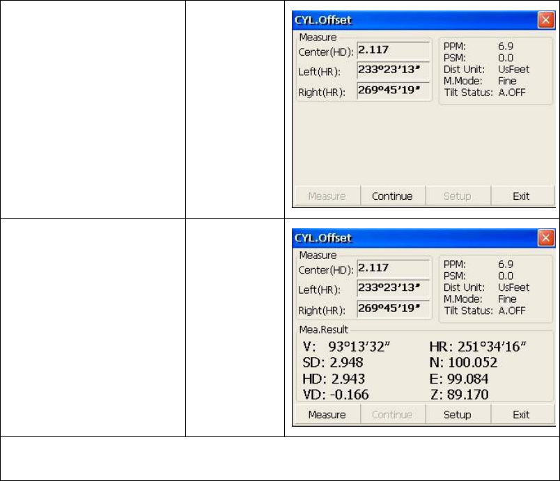
Collimate right point(P3) ④
of column surface.
②
Click “Continue ” key,and
relational values between
instrument and the center of
column(P0) can be
calculated and shown.
1)※,2)※
【Continue】
1) Click “Setup” key to set instrument height and prism height.※
2) Click “Exit” key to finish column offset measurement.※
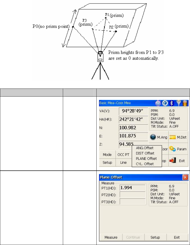
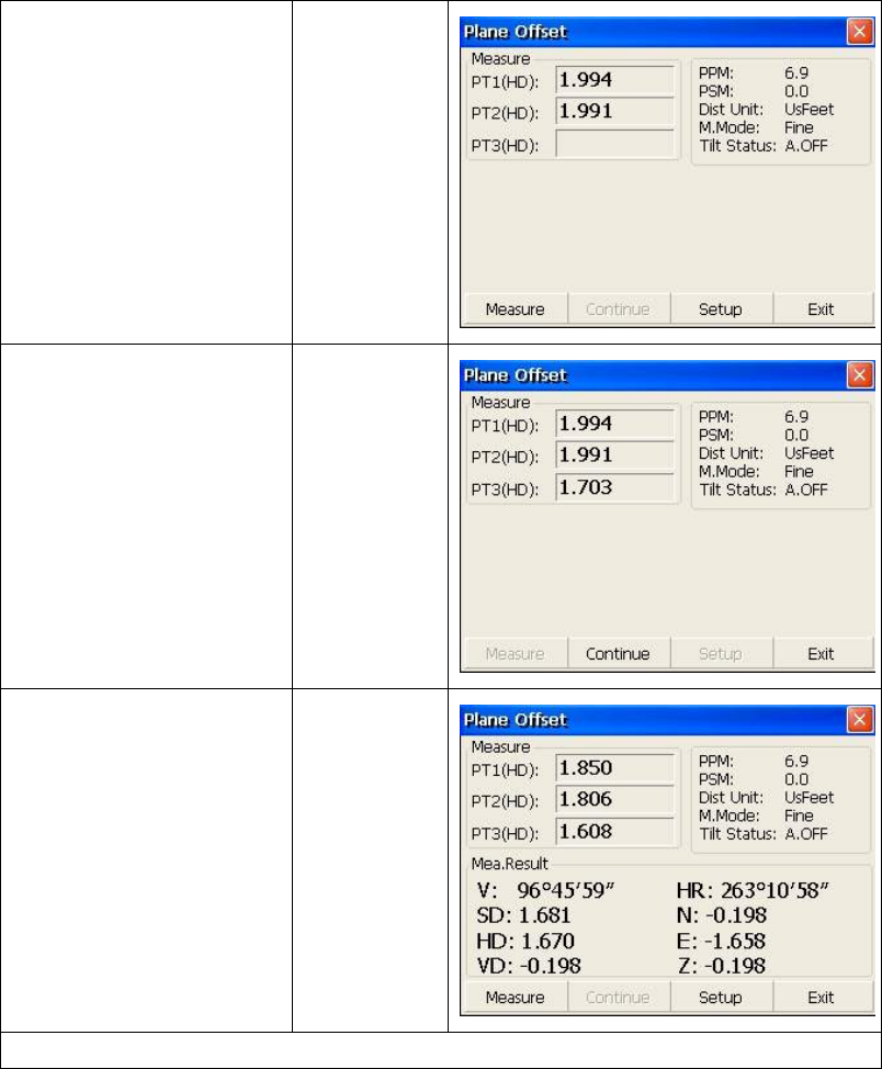
4) Plane Offset Measurement
Measuring will be taken for the place where direct measuring can not be done,for
example distance or coordinate measuring for an edge of a plane.Three random
points(P1,P2,P3) on a plane will be measured at first in the plane offset measurement to
determine the measured plane,collimate the measuring point(P0),the instrument calculates
and displays coordinate and distance value of cross point between collimation axis and of
the plane.
66
● Refer to “4.5.1” to set coordinate of occupied point.
Operation steps Keys Display
①
Click “PLANE Offset” key.
【PLANE
Offset】
Collimate prism P1,and ②
click “Measure” key. 【Measure】
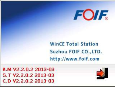
67
Collimate prism P2,and ③
click “Measure” key. 【Measure】
Collimate prism P3,and ④
click “Measure” key. 【Measure】
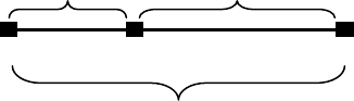
Click “Continue” key to ⑤
calculate relational values
between collimation axis
and plane.
1)※
【Continue】
1)Click “Setup” key to set instrument height and prism height.※
●If the three observing points can’t determine a plane,the system will display error
message.Thus observe the first point once again.
●When collimation axis doesn’t intersect with determined plane, the system will display
error message.
68
4.6 About
Operation:
1. Click “about” icon on desktop.
2. Press “Exit” to return the basic measurement.
69
5. Check and Adjustment
5.1 The Instrument Constant
1) Check
It is suggested to observe and compare the instrument with a testing line which is set on
stable ground with a particular accuracy, though error is not generally included in the
instrument constant. If the testing line is unavailable, you can set it for 20 meters or so by
yourselves, then check and compare it with your new instrument.
1. Select a point B on the approximately horizontal line AC with about 100 meters long.
Measure the distances of lines AB , AC and BC .
2. The instrument constant can be calculated;
instrument constant =AB+BC-AC
3. If there is a difference between the instrument standard constant and the calculated
value , colligate the measured constant and the prism constant to get a new value ,then
input the value into the instrument as a prism constant .
4. Compare length of the instrument’s testing line again with a certain standard testing
line .
5. If the difference is over 5 mm after the preceding operations, it is necessary to reset the
instrument constant .
2) Adjustment
About instrument constant setting, you must contact FOIF distributor to do that.
A B C
AB BC
AC
70
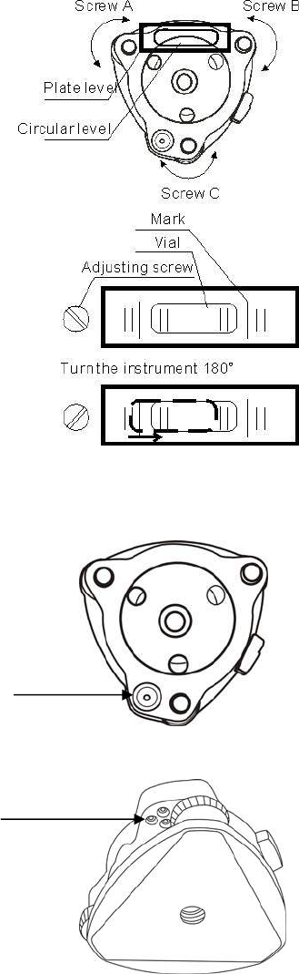
5.2 Plate Level and Circular Level
5.2.1 Plate Level
1) Check
1. Mount the instrument on a stable device (as tripod ,
adjusting device ),and fix it.
2. Level the instrument until the plate level is parallel
to a line linking leveling foot screws A and B, then
adjust the two screws to center the air bubble.
3. Turn the instrument 180°, observe the moving
direction of the bubble, if it is still centered, no
adjustment is necessary, if not, you have to adjust it.
2) Adjustment
1. Mount the instrument on a stable device and fix it.
2. Level it roughly.
3. Turn the instrument and make the plate level be
parallel to a line linking two leveling foot screws, then
adjust the two screws to center the air bubble .
4. Turn the instrument 180°, adjust the Adj-screw with
adjustment pin slightly to correct half of the bubble’s
displacement when it doesn’t move,
5. Repeat the operation (3) and (4) until the air bubble remains centered in any position .
5.2.2 Circular Level
1) Check
1. Mount the instrument on a stable device and fix it.
2. Level it accurately by the plate level.
3. Observe the bubble of the circular level, if it is
centered, no adjustment is necessary, if not, you have
to adjust it.
2) Adjustment
4. Mount the instrument on a stable device and fix it.
5. Level it accurately by the plate level.
6. Adjust the three adjusting screws to center the
bubble by a wrench.
Note: Be careful when adjusting the three screws,
and the tightening tension is identical for them.
Circular Level
Adjusting pin
71
5.3 The Optical Sight
1) Check
1. Mount the instrument on a tripod and fix it.
2. Set a cross mark target which apart from the
instrument about 50m.
3. Take the telescope sight the cross mark.
4. Observe the optical sight collimator whether
collimating the cross mark, if collimate the mark,
adjustment is not necessary; if not, adjust it.
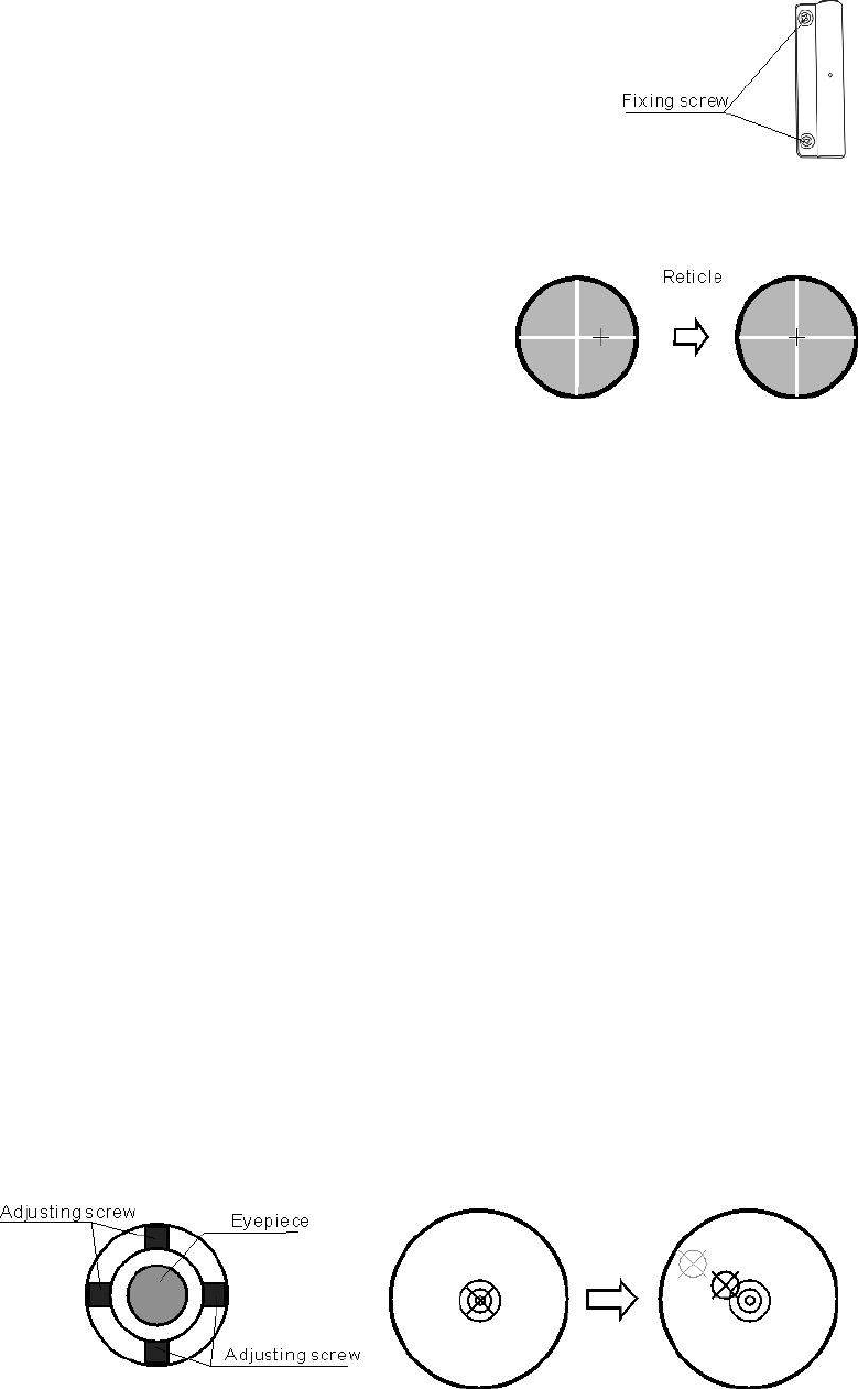
2) Adjustment
1. Mount the instrument at the tripod and fix it.
2. Set a cross mark target which apart from the
instrument about 50m.
3. Take the telescope sight the cross mark.
4. Loosen two fixing screws, adjust the collimator, then fix the two screws again.
5.4 Optical Plummet and Laser Plummet
5.4.1 Optical Plummet(factory optional)
1) Check
1. Mount the instrument at the tripod and fix it.
2. Set a cross mark under the instrument
3. Coincide the center mark of the optical plummet with the cross mark by adjusting three
leveling foot screws.
4. Turn the instrument 180°, check the center mark and cross mark, if they are coincide,
no adjustment is necessary, if not, adjust it.
2) Adjustment
1. Set the instrument on stable device and fix it.
2. Set a cross mark under the instrument.
3. Use the three leveling screws and coincide the center mark of plummet and cross mark
on the ground.
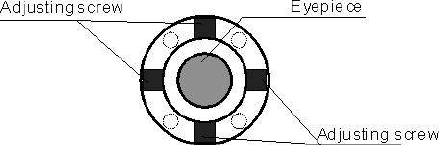
4. Rotate the instrument 180°around and take off the cover of the optical plummet
eyepiece, adjust the four adjusting screws with the adjusting pin to shift the center mark to
the cross mark, correct only one-half of the displacement in this manner.
(5) Repeat the operation in (3) and (4) until coincide the center mark of the plummet and
cross mark on the ground.
72
NOTE:
1. When adjust the screws of plummet reticle, firstly loosen the screw on the moving
direction of reticle, secondly tighten another screw by the same mount, clockwise turning
is for tightening, and anticlockwise turning is for loosening, the turning mount for
tightening or loosening should be same.
5.4.2 Laser Plummet
Check
(1)Set the instrument on stable device and fix it.
(2)Set a cross mark on the ground under the instrument.
(3)Turn the laser switch on and focus it accurately.
(4)Turn the three leveling screws until the instrument keeps leveling and the laser spot
coincides with the cross mark on the ground.
(5)Rotate the instrument 180°(200g) around and check the laser spot and cross mark,if
they coincide, adjustment is not required.
Otherwise, adjust it.
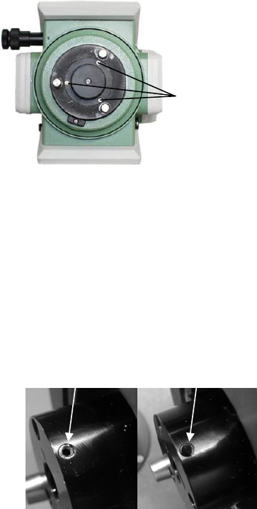
Adjustment
1. Setting up the instrument on the
checking tool or tripod which is 1.5m
apart from ground.
2. Turn on laser plummet, turn tribrach
foot screws until laser spot coincide
with cross mark. If you use tripod, make a cross mark on the laser spot directly.
3. Rotate instrument 180°around, if the laser spot is over 2mm apart from cross mark,
remove the protecting cover firstly, adjust two screws with 1.5mm hexagon wrench to
move laser spot to the cross mark, correct only one-half of the displacement in this
manner.
Adjusting details see attached figure.
4. Repeat steps 2 and 3 until laser spot coincides with cross mark always when rotate
instrument.
Note: there are three screws amounted
around laser plummet part, only two screws
are used for laser accuracy adjustment.
Protecting
cover fixing
screw
Un-adjustable
screw
Adjustable
screw
73
5.5 Vertical Cross-hair on Telescope
1) Check
(1) Set the instrument up the tripod and carefully level it.
(2) Set a point A front the instrument 50m apart;
(3) Collimate the point A and adjust the vertical tangent screw; If the point appears to
move continuously on the hair, adjustment is not required. Otherwise, adjust it.
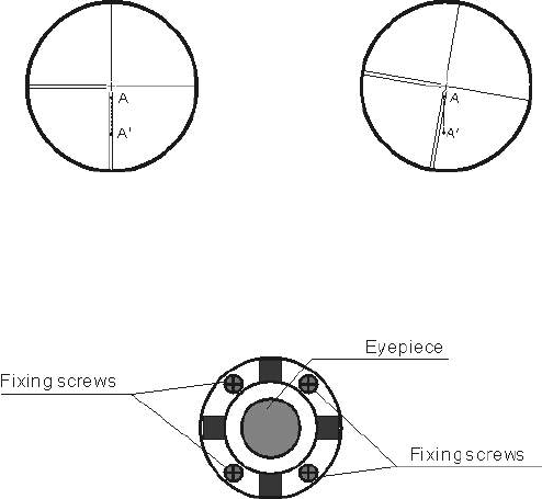
2) Adjustment
(1) Set the instrument, and set the point A front the instrument 50m apart.
(2) Take off cover of telescope eyepiece, there are 4 screws for the reticle part.
(3) Loosen all four fixing screws slightly with the cross screw-drive.
(4)Revolve the eyepiece section so that the vertical cross-hair coincides to point A, finally,
re-tighten the four screws.
(5) Repeat the checking and adjusting until there is no deviation.
NOTE:
1)After the adjustment of cross-hair, please check the collimation error and vertical index
error.
2) Refer to the chapter “5.9 EDM Optical Axis and the Telescope Sighting Axis Error” to
check the axis. At last check the collimator error again.
74
5.6 Horizontal Collimation Error C
If the telescope’s sight line isn’t perpendicular to the horizontal axis, the collimation error
will appear. The assembling, transportation and operation will cause this error.
If the collimation error isn’t over the permitted range, with the program the instrument
can correct this collimation error.
NOTE: After the program correction this deviation error is also on the instrument.
1) Check
(1) Set-up the instrument on tripod or adjustment platform and leveling accurately.
(2) Aim at the cross-hairs of collimator or the obvious target at a distance. Get the face
left angle reading H1 and the face right angle reading Hr.
(3) Calculating the horizontal collimation error C according to C=(Hl- Hr±180°)/2,if
C<8″, no adjustment will be necessary. If C>8″, proceed with the following adjustment.
2) Adjustment by program:
Set-up the instrument on tripod or adjustment platform, and leveling accurately.
Procedures:
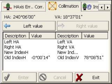
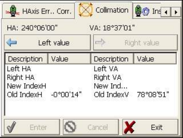
1. Power on, run the software “TS810Setup”, on the screen tap ◄ or ► keys until
Collimation displays, tap it to display collimation error and vertical index error setting
menu.
2. Aim at the cross-hair of collimator at telescope left, tap “Left value” to read the
horizntal and vertical angles.
3. Aim at the cross-hair of coillmator at telescope right, tap “Right value” to read the
horzontal and vertical angles.
4. The software will calculate the new collimation error and vertical index error
automatically.
5. Tap “Enter” to save the new values, or tap “Cancel” to use old values.
Note:
The adjustment can be performed by the program when C<30″, if C>30″, adjust the
75
reticle.
Reticle Adjusting:
1. Rotate the instrument in face right position, turning horizontal tangent screw until
Hr′=Hr+C.
2.Loosen the shield of telescope’s reticle.
3. Adjusting two screws at left and at right until the vertical hairs of telescope’s reticle
coincides with the cross-hairs of collimator or target.
4. Repeat the check and adjustment procedure until the error is accepted.
NOTE:
1. When adjust the screws of reticle, firstly loosen the screw on the moving direction of
reticle, secondly tighten another screw by the same mount, clockwise turning is for
tightening, and anticlockwise turning is for loosening, the turning mount for tightening or
loosening should be same.
2. After the reticle adjustment, it is necessary to adjust the vertical index error by
program.
5.7 Vertical Index Error
The deviation between vertical circle zero position and horizontal direction is vertical
index (i), it is necessary to concern this error when measure vertical angle. The instrument
program applied a formula to remove this error. This correction can offer the index for the
formula.
Warning: Before starting this operation, be sure to read manual carefully, otherwise it may
cause data faulty.
Because of the close relationship between vertical index and compensator zero position, it
is necessary to check and adjust compensator zero position when adjust the vertical circle,
the value should be stable when reading.
1) Check:
Please adjust the reticle of telescope and correct the collimation error before this
operation.
(1) Mount the instrument at the tripod or a stable device and level it accurately, then turn
on the instrument.
(2) Aim at the cross-hairs of collimator or the obvious target at a distance, VA should be
76
about ±10°. Read the face left angle Vl and face right angle Vr.
(3) Calculate the index error according to the formula below:
i = ( Vl+Vr-360°)/2
(4)If I<10〞, no adjustment is necessary , or you have to adjust it .
2) Adjustment by program:
Set-up the instrument on tripod or adjustment platform, and leveling accurately.
Procedures
1. Power on, run the software “TS810Setup”, on the screen tap ◄ or ► keys until
Collimation display, tap it to display collimation error and vertical index error setting
menu.
2. Aim at the cross-hair of collimator at telescope left, tap “Left value” to read the
horizntal and vertical angles.
3. Aim at the cross-hair of coillmator at telescope right, tap “Right value” to read the
horzontal and vertical angles.
4. The software will calculate the new collimation error and vertical index error
automatically.
5. Tap “Enter” to save the new values, or tap “Cancel” to use old values.
77
5.8 EDM Optical Axis and the Telescope Sighting Axis Error
It is necessary to check this error after the adjustment of telescope reticle error.
1)Checking (For 350 series)
(1) Install the instrument at the tripod or a stable device and level it accurately, then
power on the instrument.
(2) Set a prism about 2m far away from the instrument.
(3) Aim at the prism center with telescope reticle.
(4) Enter EDM signal testing screen.
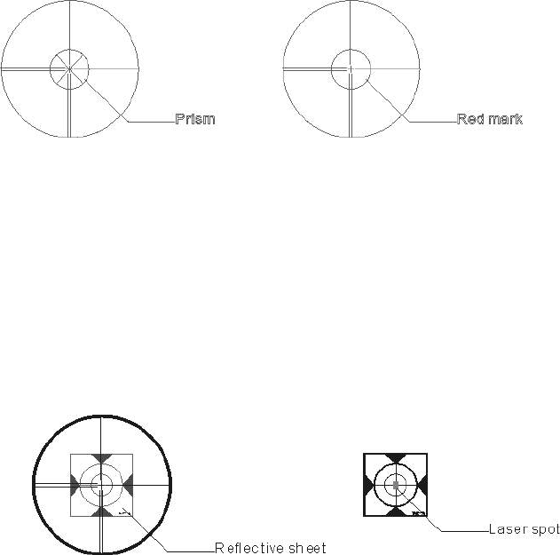
(5) Observe through eyepiece, turn the focusing knob until the red mark is clear, if the
deviation between mark and cross-hair is not over 1/5 of red mark diameter, adjustment is
unnecessary.
2)Checking (For RTS350 series)
(1) Install the instrument at the tripod or a stable device and level it accurately, then
power on the instrument.
(2) Set a reflective sheet about 5m-20m far away from the instrument.
(3) Aim at the sheet cross-mark with telescope reticle.
(4) Enter EDM signal testing screen.
(5) Observe the laser spot, if the laser spot coincides with the cross-mark of reflective
sheet, adjustment is unnecessary.
NOTE:
Laser radiation do not stare into beam.
3)Adjustment
If the instrument needs adjustment, please contact with our dealers.
78
6. Specifications
RTS350 series
Telescope
Length 156mm
Image Erect
Magnification 30×
Aperture 45mm
Field of view 1°30′
Minimum focus 1.0m
Angle measurement
Reading system Absolute encoder
Circle diameter 79mm
Angle unit 360degree/400gon/6400mil, selectable
Minimum display 0.5″/1″/5″,selectable
0.1mgon/0.2mgon/1mgon, selectable
Detecting mode Double
Accuracy 2″/5″
Distance measurement(R500)
Display resolution(m/inch selectable) 0.1mm/1mm
Laser class Prism Class 1
Reflectorless/Reflective sheet Class 3R
Distance unit m/ft, selectable
Measurement range(good condition) Single prism 1 to 3000m
Reflective sheet/RP60 1 to 800m
Reflectorless 1 to 500m
Mini-reading Fine mode 0.1mm/1mm(0.001ft/0.01ft)
Tracking mode 10mm (0.1ft)
Accuracy Prism:2mm+2ppm/1mm+1.5ppm(Optional)
Reflective sheet/RP60:3mm+2ppm
Reflectorless:1-200m:3mm+2ppm/≥200:5mm+3ppm
Measurement time Initial: 2.5s
Fine mode: 1.5 s
Rapid mode: 0.9s
Tracking mode: 0.5s
Prism typ.1.0-1.5s
Reflective sheet/Rp60 typ.1.5s
79
Reflectorless typ.1.5-5s,max.20s
Temperature unit / , selectable℃℉
Pressure unit hPa/mmHg/inchHg, selectable
Temperature input range -30 to +60 (1 steps)℃℃℃
Pressure input range 510hPa to 1066hPa(1hPa setps)
Prism constant condition -99.9mm to +99.9mm
Refraction and earth curvature correction OFF/0.14/0.2, selectable
Reflecting prism constant correction -99.9mm to +99.9mm
Distance measurement(R1000)
Laser class
Prism standard mode/Prism long mode Class 1/ Class 2
Reflective sheet Class 2
Reflectorless standard mode Class 2
Reflectorless long mode Class 3R
Measurement range(good condition)
Standard mode/Prism 1 to 3500m
Long mode/Prism 1 to 6000m
Reflective sheet/RP60 1 to 1200m
Reflectorless 1 to 1000m
Accuracy/typical measuring time(max.20s)
Prism standard mode:1mm+1.5ppm/1.0s-5.0s
Prism long mode:2mm+2.5ppm/0.7s-6s
Reflective sheet/RP60:2mm+2ppm/1s-5s
Reflectorless:1-500m:2mm+2ppm/0.7s-6s>500m:4mm+2ppm/3s-12s
Level vial sensitivity
Plate level 30″/2mm
Circular level 8′/2mm
Compensation Dual-axis
System Liquid type
Range ±3′
Resolving power 1″
Data processing system
Operating system Windows CE
CPU 32 bit
Optical plummet(Factory optional)
Accuracy ±0.8mm/1.5m
Image Erect
80
Magnification 3×
Focusing range 0.5m~∝
Field of view 4°
Laser plummet(Standard)
Accuracy ±1.0mm/1.5m
Laser class Class 2/IEC60825-1
Laser spot size/brightness Adjustable
Laser wave length 635nm
Display
LCD 3.5″ color TFT LCD(320×240dots), touch screen
transflective sunlight readable display
Internal memory
Internal memory SD Card
Power
Battery 3400 mAh Li-ion Rechargeable battery
Voltage 7.4V DC
Continuous operation time About 10 hours(single distance measurement every 30 seconds)
Chargers FDJ6-Li(100V to 240V)
Charging time (at +20 ) Approx. 4 hours℃
Application programs
Data collection/Stake out/Resection/REM/MLM/Point to line
AREA/Z coordinate/OFFset/3D Road/Traverse adjustment
Tape measurement/section/axis positioning measurement
Others
CPU ARM9 Core
Memory 2G internal memory
Guide Light System Factory optional
Sensors Built-in temperature and pressure sensors
Keyboard Alphanumerical illuminated key board,both sides
Operating temperature -20°~+50℃
Storage temperature -40°~+70℃
Dimension(W×D×H) 210×210×360mm
Weight(including batteries) 5.5kg
Dimensions(W×D×H) 185×220×360mm
Interface USB host/USB slave/RS-232C/Bluetooth(Optional)
Water and dust protection IP55 (IEC60529)
Data collector PS236,fully rugged PDA(Optional)
81
8. Standard components
● Carrying case 1 each
● Instrument 1 each
● Battery 2 each
● Charger 1 each
● Adjusting pins 2 each
● Cleaning cloth 1 each
● Cleaning brush 1 each
● Screwdriver 1 each
● Wrench 2 each
● Silica gel 1 each
● Instruction manual 2 each
● CD 1 each
● USB Communication cable 1 each
● RS232C Communication cable 1 each
● Rainproof 1 each
● Reflective sheet/RP30 4 each
● Reflective sheet/RP60 1 each
● Laser caution sign board 1 each
82
Appendix I: Atmospheric correction formula and
chart(Just for reference)
Factory setting: temperature: 20 , pressure:1013hpa, 0ppm ℃(RTS)
temperature: 20 , pressure:1013hpa, 0ppm ℃(RTS)
The correction:
Kpt=274.417-0.2905*p/(1+0.0036*t)……………….. RTS
Kpt=278.960-0.2902*p/(1+0.0036*t)………………...RTS
Where: p--Pressure value (hPa)
t--Temperature value (℃)
Kpt--Atmospheric correction (ppm)
Example:
t=20 , p=1013hpa, L0=1000m.℃
Then: Kpt=0ppm (RTS) Kpt=4ppm (RTS)
L=L0(1+Kpt)=1000×(1+0×10-6)=1000.000m (RTS)
L=L0(1+Kpt)=1000×(1+4×10⁻⁶)=1000.004m (RTS)
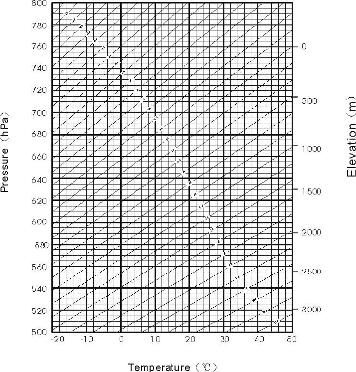
The atmospheric value is obtained easily with the atmospheric correction chart.
Find the measured temperature in horizontal axis, and pressure in vertical axis on
the chart.
Read the value from the diagonal line, which is the required atmospheric
correction value.
83
For RTS series
84
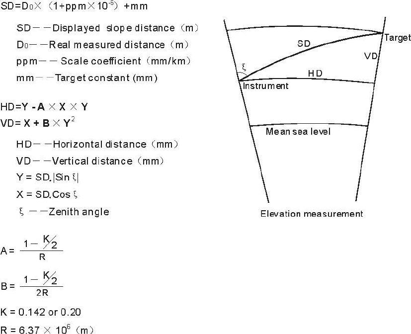
Appendix II: Correction for refraction and earth curvature
Considering the correction of refraction and earth curvature for distance
measurement, the formula for slope distance, horizontal distance and vertical
distance applied in the instrument are as followings:
The conversion formula for horizontal and vertical distance is as follows when
correction for refraction and earth curvature is not applied:
HD=SD COS§ VD=SD SIN§∣∣
NOTE:
The factory setting for the refraction coefficient K is 0.142.
Refer to the section 3.10 to change the value of K.
85
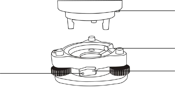
Appendix III: Assembling and disassembling for three-jaw
tribrach
It is convenient to assemble or disassemble the instrument from tribrach by
loosen or tighten the tribrach clamp.
Disassemble
(1) Rotate the tribrach clamp anticlockwise until the lever is loosen.
(2) One hand hold up the tribrach, another hand hold the carry handle of the
instrument and lift out the instrument from the tribrach.
Assemble
(1) Put the instrument into the tribrach lightly, let the communication port
against in the indentation of the tribrach..
(2) Rotate the tribrach clamp clockwise until the lever is tighten.
Note: Fix the tribrach clamp
If the instrument don’t need assembly or disassembly from tribrach frequently, it
is necessary to fix the tribrach clamp by fixed screw to avoid the disassembly by
accident.
Screw out the fixed screw by driver to fix the clamp.
Positing block
Positing groove
Tribrach clamp
Fixed screw

86
NOTE:
These designs, figures and specifications are subject to change without
notice. We shall not be held liable for damages resulting from errors in
this instruction manual.
Suzhou FOIF Co.,Ltd.
Tel: + 86-512-65224904
Fax: +86-512-65230619
+86-512-65234905
E-mail:internationalsales@foif.com.cn
Add: 18 Tong Yuan Road, Suzhou 215006, P.R.China
Web: http://www.foif.com