SYRIS Technology RD200-U1-G UHF RFID Desktop Reader User Manual RD200 RD300 tool manual V0206
SYRIS Technology Corp. UHF RFID Desktop Reader RD200 RD300 tool manual V0206
UserManual.wiki
>
SYRIS Technology
>
RD200 U1 G User Manual
Users Manual.pdf
Navigation menu
Upload a User Manual
Namespaces
Wiki Guide
HTML
PDF
Info
Views
User Manual
Discussion / Help
Navigation
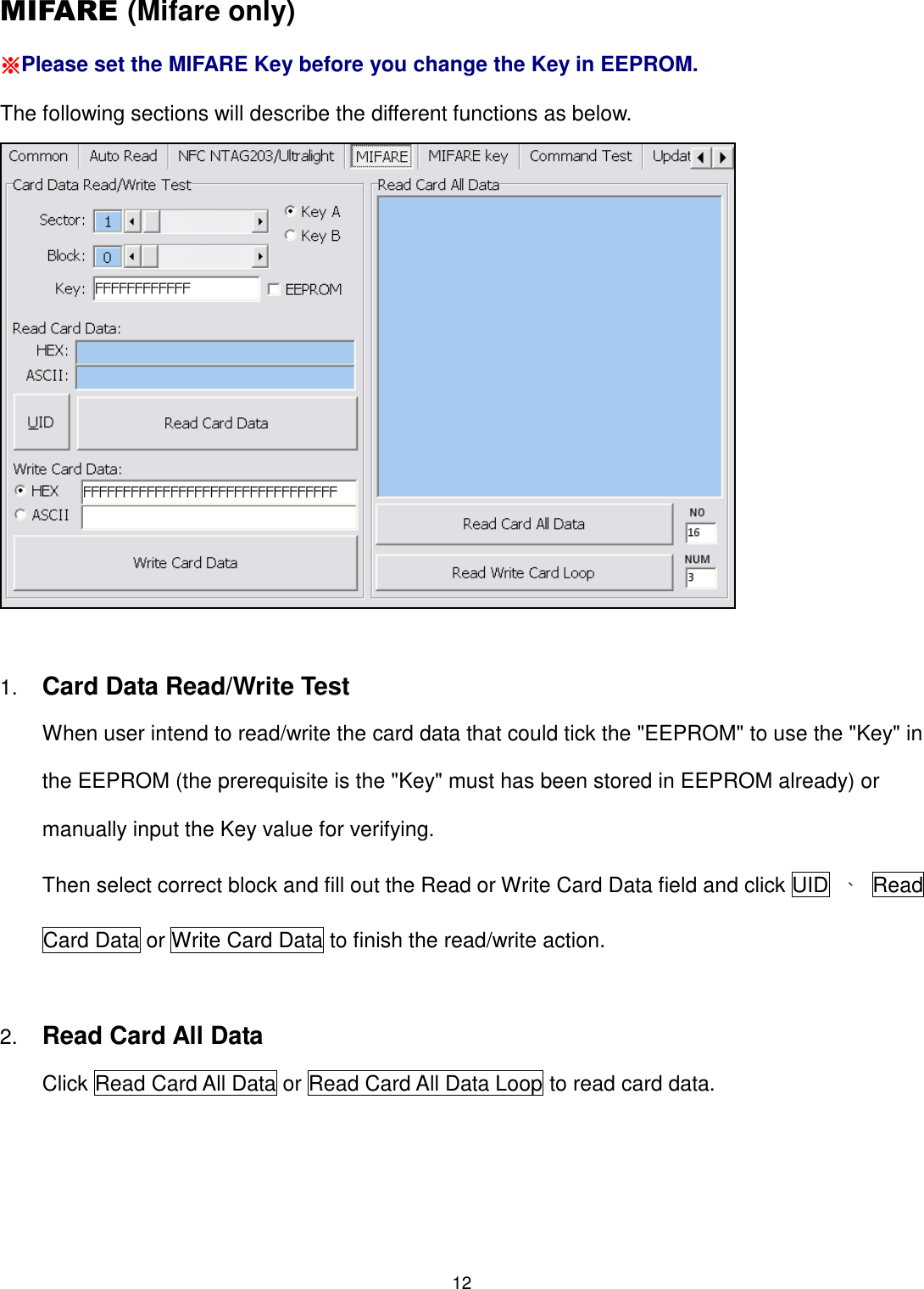
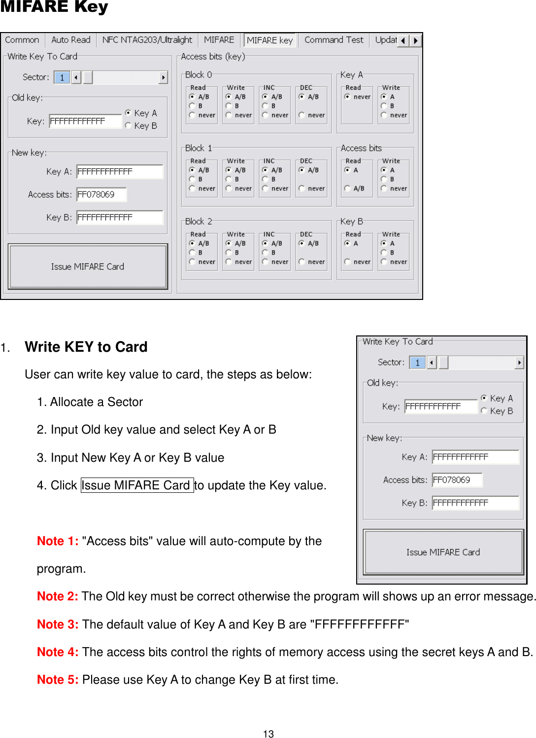
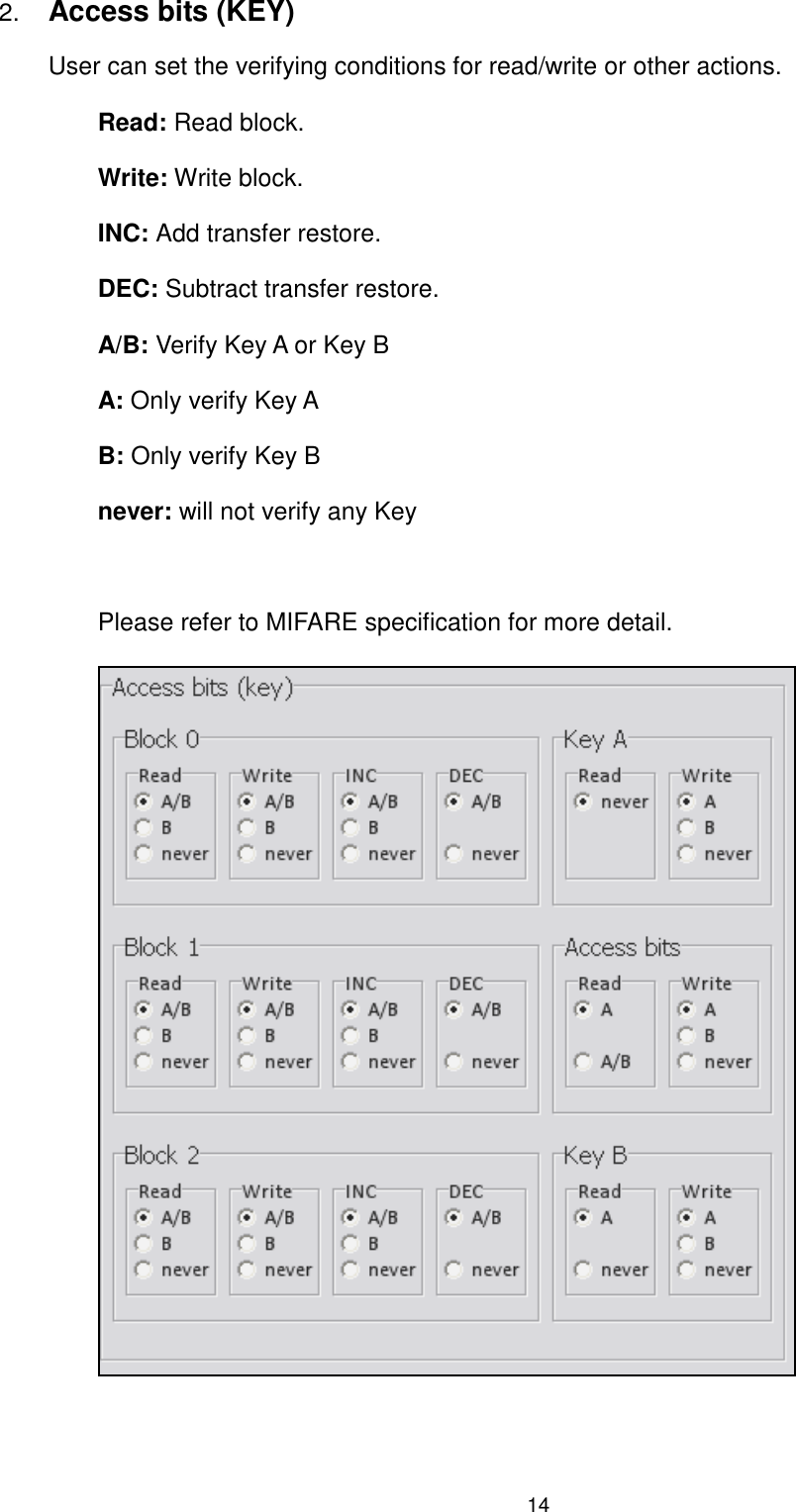
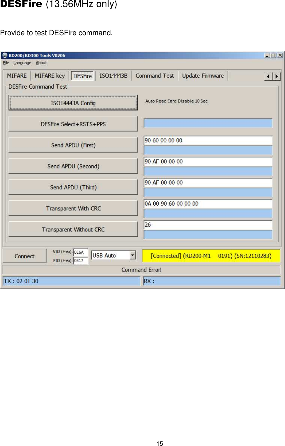
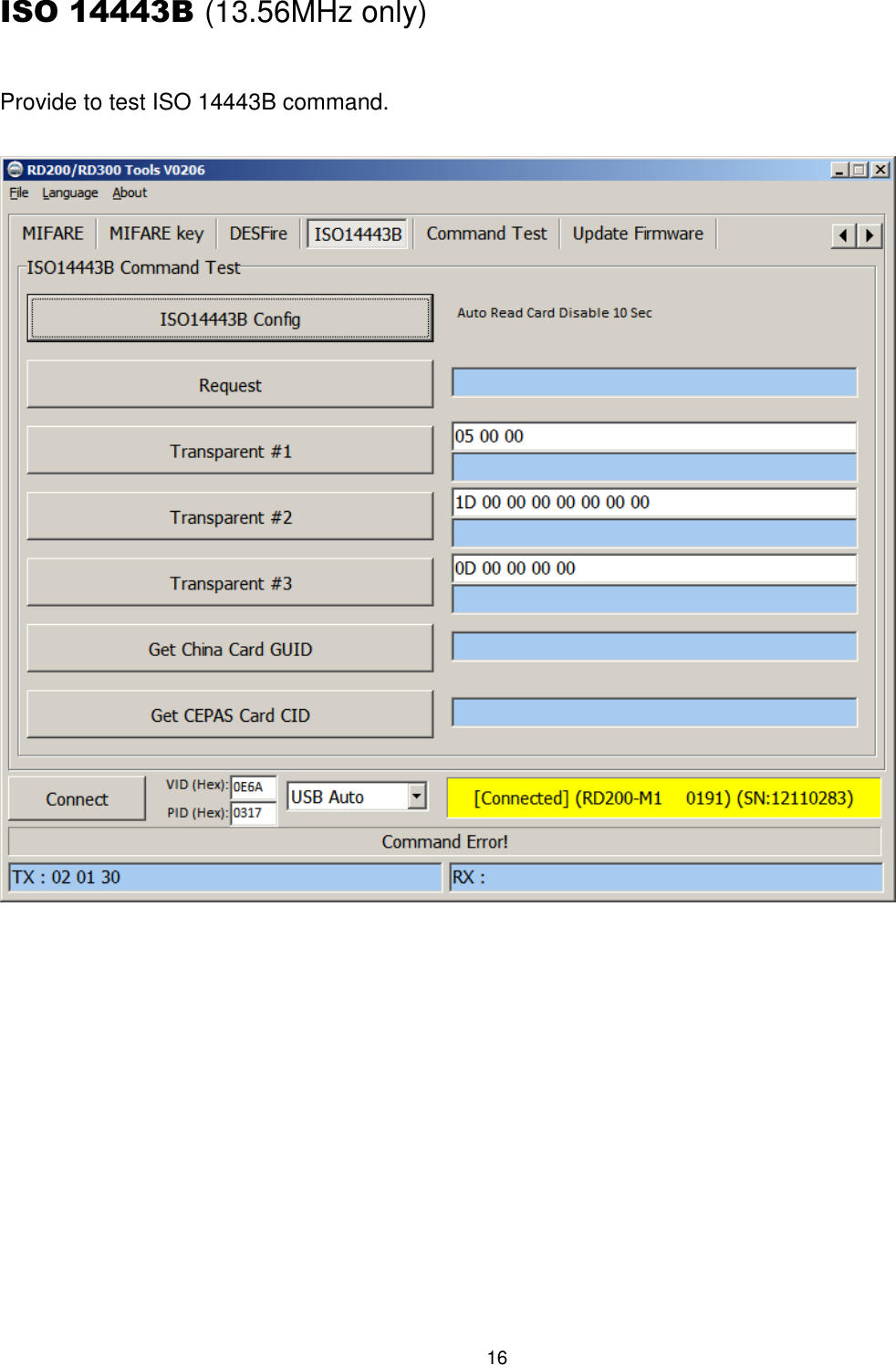
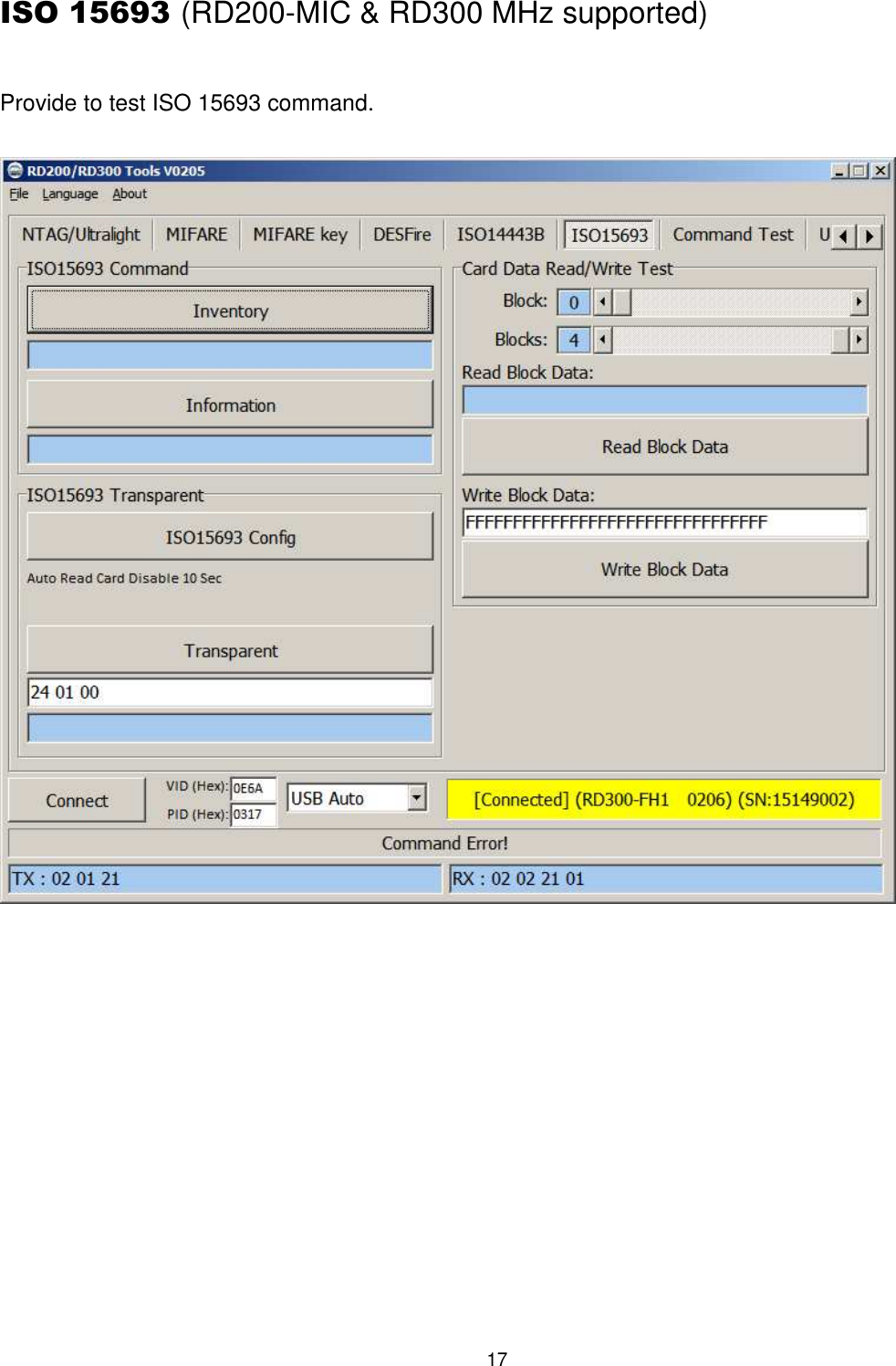
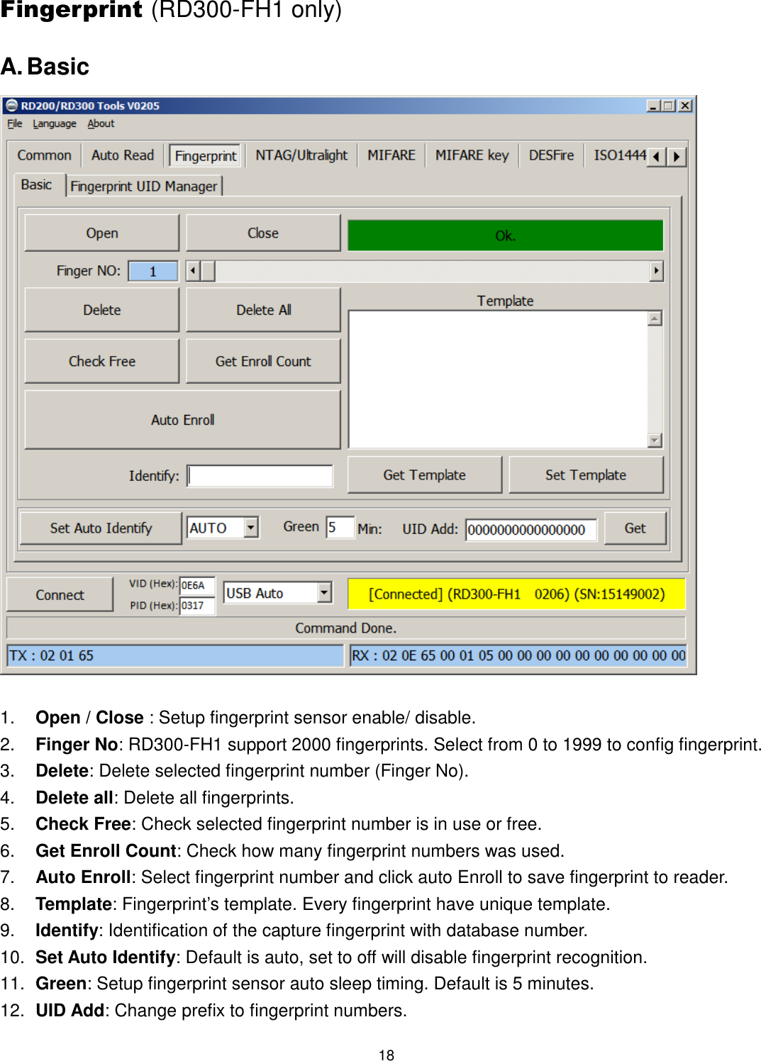
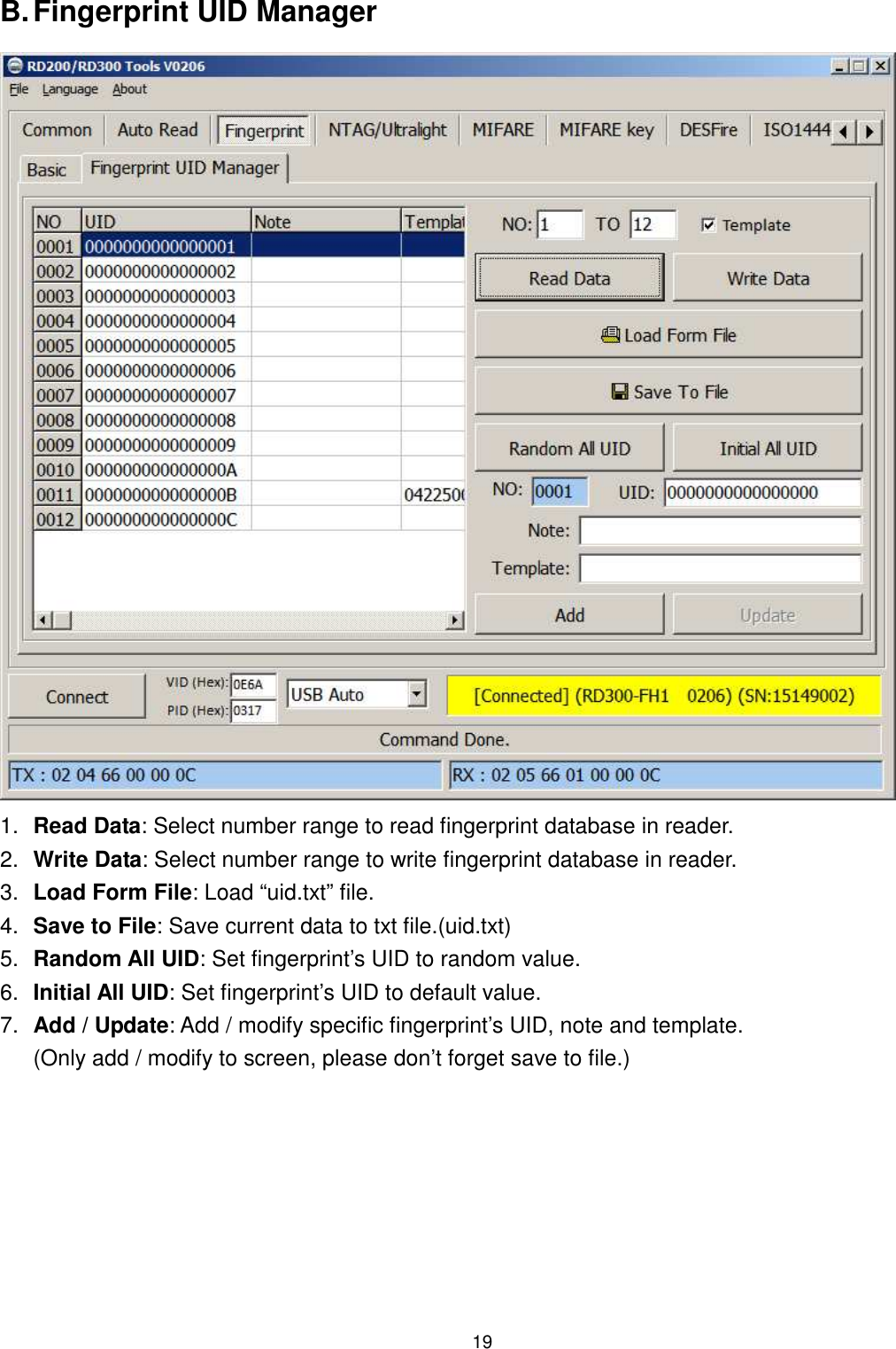
![7 6. Send ID Format This tool provide many ID format to choose, such as 4~16 numbers of hexadecimal and 4~13 numbers of decimal. Also can put comma, space…etc. into the ID format, after ticked the items then click Set to finish the setting procedure, or click Get Current Setting to read current setting from the reader. The ID format example as below: ID Format Example Result 4H 58E8 6H D558E8 8H 00D558E8 10H 1800D558E8 16H 0000001800D558E8 32H 00000000000000000000001800D558E8 5D 47295 8D 01226943 10D 0001226943 13D 0098785474751 4D 6493 FDX (LF only) 000000001226943 16H + Card ID Reverse E858D50018000000 16H + Comma 0000001800D558E8, 16H + Brackets [0000001800D558E8] 4D + Space 1928 1928 16H + Quotation '0000001800D558E8'](https://usermanual.wiki/SYRIS-Technology/RD200-U1-G/User-Guide-2730504-Page-8.png)