SYRIS Technology RD200-U1-G UHF RFID Desktop Reader User Manual RD200 RD300 tool manual V0206
SYRIS Technology Corp. UHF RFID Desktop Reader RD200 RD300 tool manual V0206
Users Manual.pdf
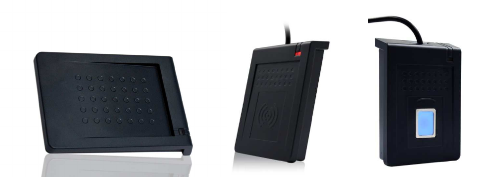
RD200/300
T
OOL
O
PERATION MANUAL
V02.06
1
Installation ........................................................................................................................................ 2
Driver installation (For change to virtual COM port mode) ............................................................... 3
Common Setting .............................................................................................................................. 4
Auto Read (13.56 MHz only) ............................................................................................................ 9
NTAG/Ultralight (13.56 MHz only) .................................................................................................. 10
MIFARE (Mifare only) ..................................................................................................................... 12
MIFARE Key .................................................................................................................................. 13
DESFire (13.56MHz only) .............................................................................................................. 15
ISO 14443B (13.56MHz only) ........................................................................................................ 16
ISO 15693 (RD200-MIC & RD300 MHz supported) ....................................................................... 17
Fingerprint (RD300-FH1 only) ........................................................................................................ 18
Command Test ............................................................................................................................... 20
Firmware Update ........................................................................................................................... 21
2
Installation
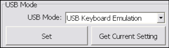
The default setting of USB Mode is USB Keyboard Emulation. This Keyboard mode would send
an "Enter" signal when read the card. If user let cursor focus on "Set" button and read the card that
will press the "Set" button at the same time.
3
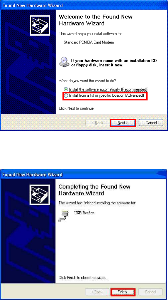
Driver installation (For change to virtual COM port mode)
1. Follow firmware update procedure to change virtual COM port mode firmware.
(ex. RD200_U1_COM_V0191_20150316.SYB)
2. Connect RD200/RD300, system will automatically pop-up the "Found New Hardware Wizard"
window for install the driver.
3. Allocate the driver folder, and then complete the installation.
(SYRIS_RFID_DVD\RD200\Driver)
4
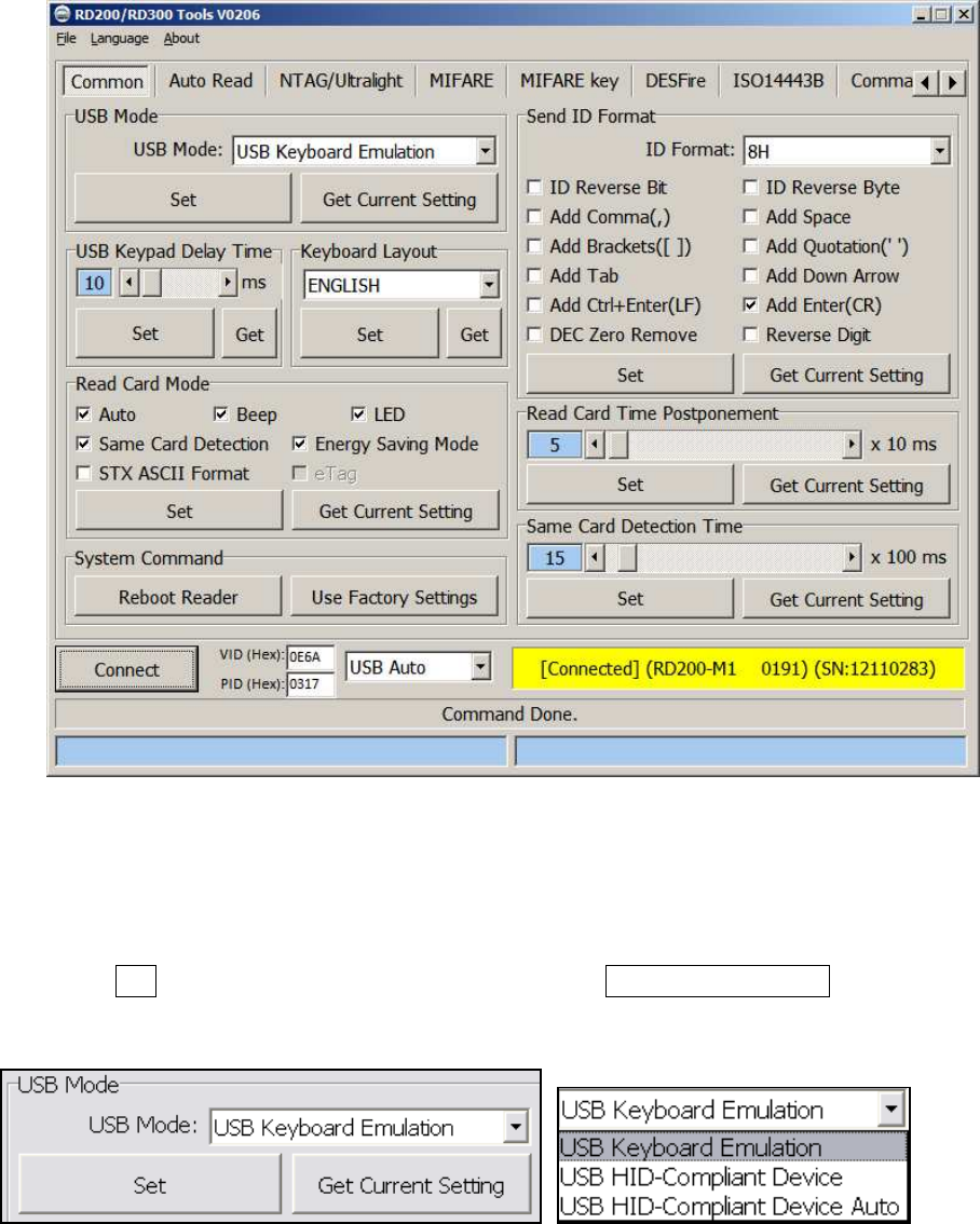
Common Setting
1.
USB Mode
There are three selections of USB modes in "USB auto" connection, after selected the mode
then click Set to finish the setting procedure, or click Get Current Setting to read current
setting from the reader.
USB Keyboard Emulation:
The device can emulate keyboard to send character or string to host terminal.
USB HID-Compliant Device:
5
Device response data when received protocol command, and the data will be queued in device
buffer.
USB HID-Compliant Device Auto Send:
The device sends UID to host terminal after read card.
2.
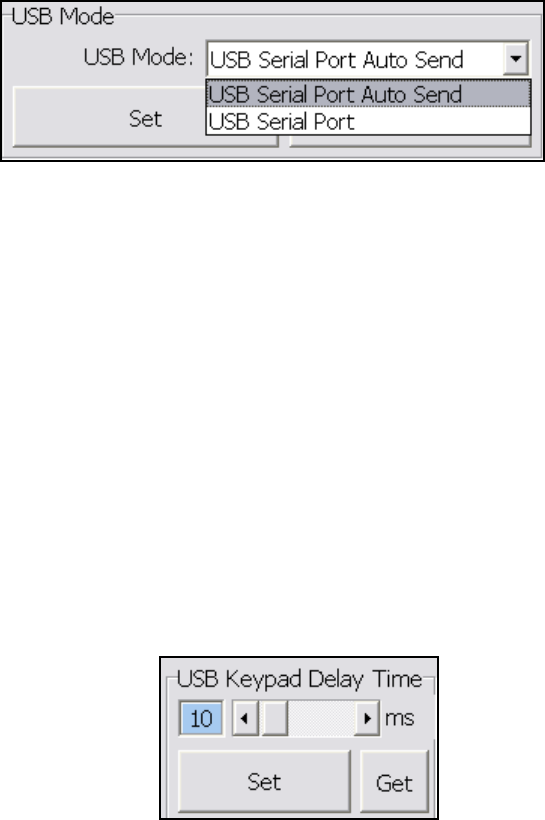
Virtual COM Port mode (Need update firmware)
There are two selections of USB modes in "COM x" connection.
USB Serial Port Auto Send:
::
:
The device send UID to host terminal after read card.
USB Serial Port:
::
:
Device response data when received protocol command, and the data will be queued in device
buffer.
3.
USB Keypad Delay Time
In this mode, you can set keypad delay timing to reduce the key code sending speed when
read tag.
6
4.
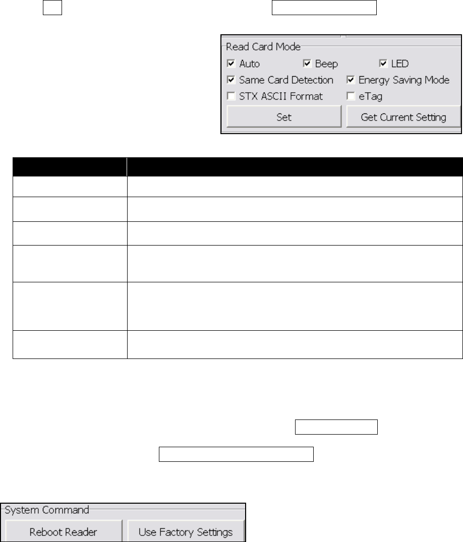
Read Card Mode
In this mode, program provided different options for user to choose, after ticked the options,
just click Set to finish the setting procedure, or click Get Current Setting to read current setting
from the reader.
Options Descriptions
Auto Automatically read card
Beep Prompt the beep sound or not.
LED Flash the LED when read the card.
Same Card Detection
If continuously read the same card, user has to wait around 1.5 sec then
could read again.
Energy Saving Mode Provide more energy saving method.
(It is not recommend to use in writing card blocks or several cards)
eTag Read Taiwan ETC eTag format.
5. System Command
This tool provides two system commands; user can use Reboot Reader to reboot the RD200
reader. The other command is Use Factory Default Settings which can restore the reader
settings to initial settings.
7
6.
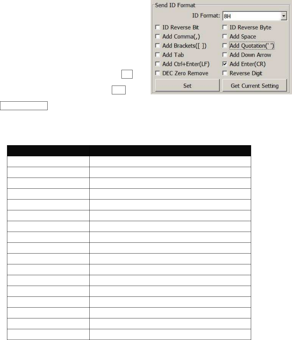
Send ID Format
This tool provide many ID format to choose,
such as 4~16 numbers of hexadecimal and
4~13 numbers of decimal.
Also can put comma, space…etc. into the ID
format, after ticked the items then click Set to
finish the setting procedure, or click Get
Current Setting to read current setting from the reader.
The ID format example as below:
ID Format Example Result
4H 58E8
6H D558E8
8H 00D558E8
10H 1800D558E8
16H 0000001800D558E8
32H 00000000000000000000001800D558E8
5D 47295
8D 01226943
10D 0001226943
13D 0098785474751
4D 6493
FDX (LF only) 000000001226943
16H + Card ID Reverse E858D50018000000
16H + Comma 0000001800D558E8,
16H + Brackets [0000001800D558E8]
4D + Space 1928 1928
16H + Quotation '0000001800D558E8'
8
7.
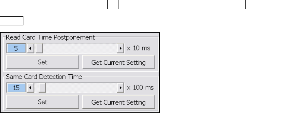
Read Card Time Postponement / Same Card Detection Time
Read Card Time Postponement: The intermission time of card reading.
Same Card Detection Time: The intermission time of same card detection.
After adjusted the time then click Set to finish the setting procedure, or click Get Current
Setting to read current setting from the reader.
9
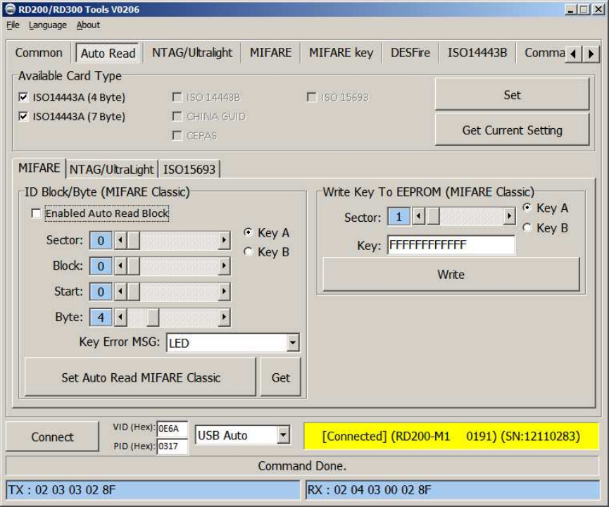
Auto Read (13.56 MHz only)
Available card type: Setup read card type.
Set auto read Mifare Class or Ultralight in this tab to read specific block automatically.
1. Enable and select correct block.
2. Click set auto read.
3. Reader will always read selected block automatically.
Write Key to EEPROM: Save your Mifare key to reader.
10
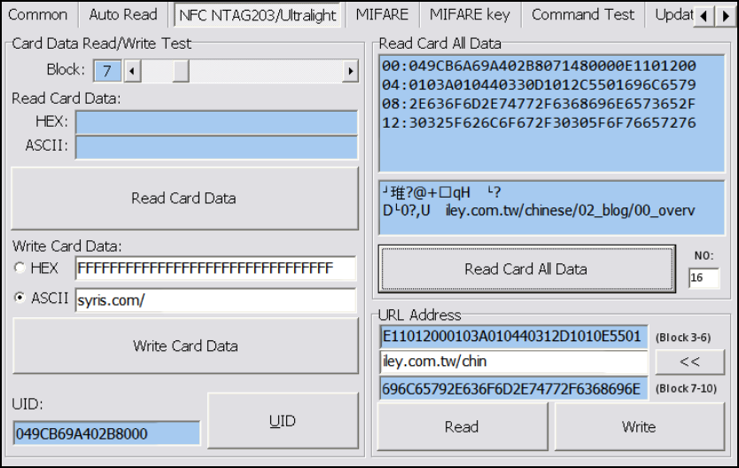
NTAG/Ultralight (13.56 MHz only)
1. Read Card Data: Select correct block to read NFC tag’s data.
2. Write Card Data: Select correct block to write NFC tag’s data.
(Recommend select HEX code to write.)
3. UID : Read tag’s UID
4. Read Card All Data: Input max block number in “NO” and start to read all data.
5. URL address: This is a simple demo to read/write URL to tag.
11
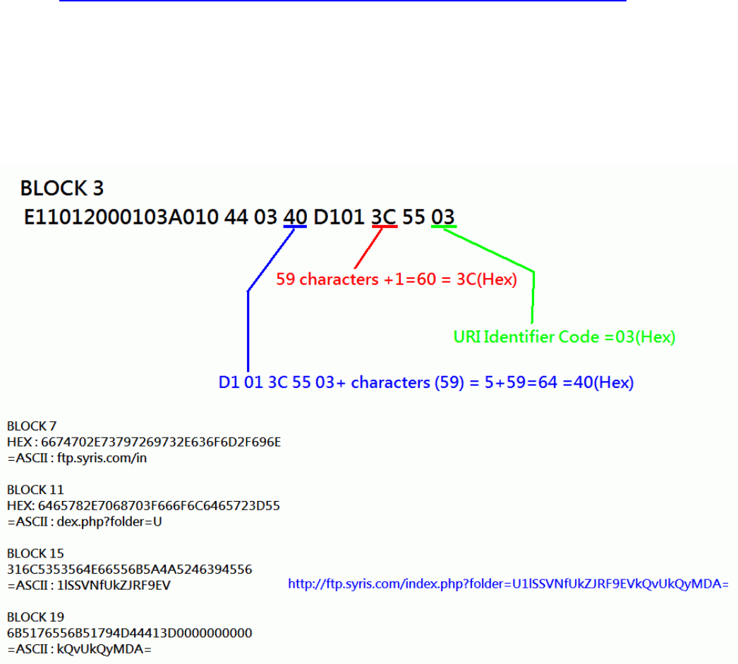
For example
Write a URL to NTAG203. (NDEF specification)
http://ftp.syris.com/index.php?folder=U1lSSVNfUkZJRF9EVkQvUkQyMDA=
URI is "http://" (URI Identifier Code =03(Hex))
String is "ftp.syris.com/index.php?folder=U1lSSVNfUkZJRF9EVkQvUkQyMDA="
(Total 59 characters)
You need write block with RD200 tool as blow.
12
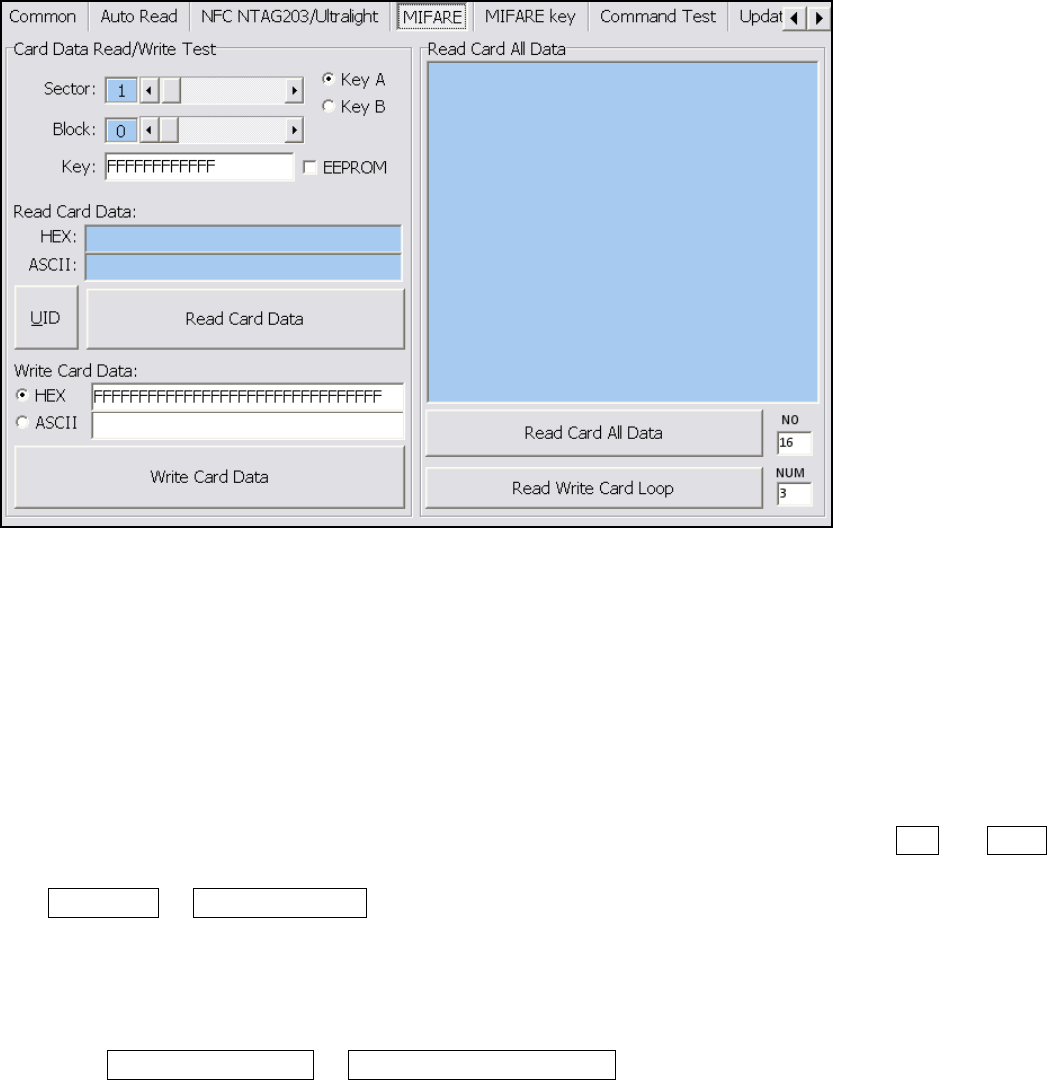
MIFARE (Mifare only)
※
※※
※Please set the MIFARE Key before you change the Key in EEPROM.
The following sections will describe the different functions as below.
1.
Card Data Read/Write Test
When user intend to read/write the card data that could tick the "EEPROM" to use the "Key" in
the EEPROM (the prerequisite is the "Key" must has been stored in EEPROM already) or
manually input the Key value for verifying.
Then select correct block and fill out the Read or Write Card Data field and click UID 、 Read
Card Data or Write Card Data to finish the read/write action.
2.
Read Card All Data
Click Read Card All Data or Read Card All Data Loop to read card data.
13
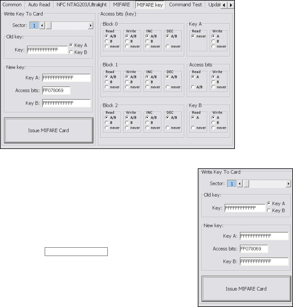
MIFARE Key
1.
Write KEY to Card
User can write key value to card, the steps as below:
1. Allocate a Sector
2. Input Old key value and select Key A or B
3. Input New Key A or Key B value
4. Click Issue MIFARE Card to update the Key value.
Note 1: "Access bits" value will auto-compute by the
program.
Note 2: The Old key must be correct otherwise the program will shows up an error message.
Note 3: The default value of Key A and Key B are "FFFFFFFFFFFF"
Note 4: The access bits control the rights of memory access using the secret keys A and B.
Note 5: Please use Key A to change Key B at first time.
14
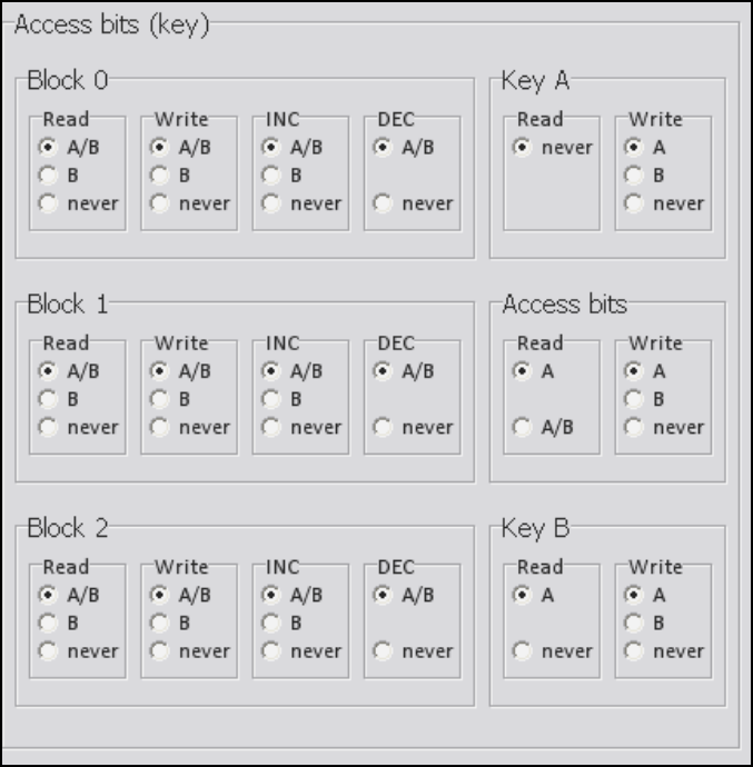
2.
Access bits (KEY)
User can set the verifying conditions for read/write or other actions.
Read: Read block.
Write: Write block.
INC: Add transfer restore.
DEC: Subtract transfer restore.
A/B: Verify Key A or Key B
A: Only verify Key A
B: Only verify Key B
never: will not verify any Key
Please refer to MIFARE specification for more detail.
15
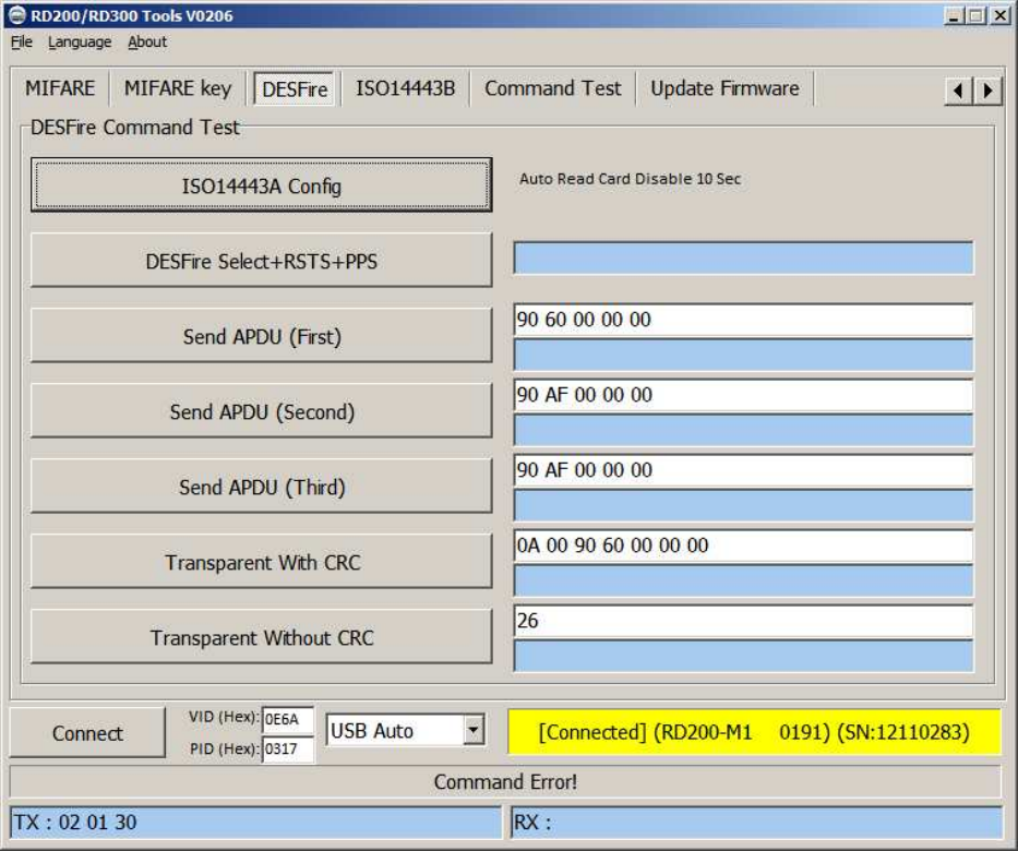
DESFire (13.56MHz only)
Provide to test DESFire command.
16
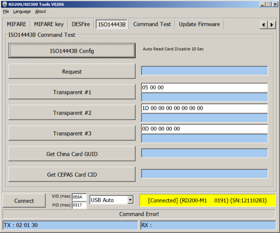
ISO 14443B (13.56MHz only)
Provide to test ISO 14443B command.
17
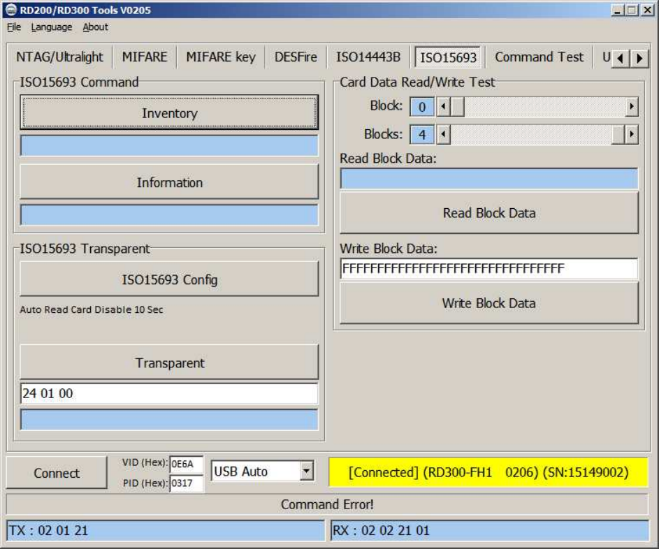
ISO 15693 (RD200-MIC & RD300 MHz supported)
Provide to test ISO 15693 command.
18
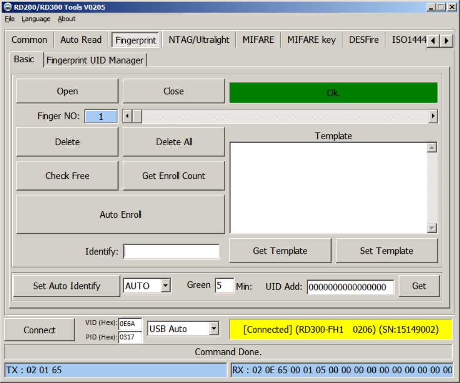
Fingerprint (RD300-FH1 only)
A. Basic
1. Open / Close : Setup fingerprint sensor enable/ disable.
2. Finger No: RD300-FH1 support 2000 fingerprints. Select from 0 to 1999 to config fingerprint.
3. Delete: Delete selected fingerprint number (Finger No).
4. Delete all: Delete all fingerprints.
5. Check Free: Check selected fingerprint number is in use or free.
6. Get Enroll Count: Check how many fingerprint numbers was used.
7. Auto Enroll: Select fingerprint number and click auto Enroll to save fingerprint to reader.
8. Template: Fingerprint’s template. Every fingerprint have unique template.
9. Identify: Identification of the capture fingerprint with database number.
10. Set Auto Identify: Default is auto, set to off will disable fingerprint recognition.
11. Green: Setup fingerprint sensor auto sleep timing. Default is 5 minutes.
12. UID Add: Change prefix to fingerprint numbers.
19
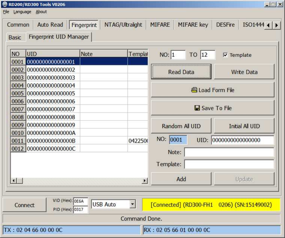
B. Fingerprint UID Manager
1. Read Data: Select number range to read fingerprint database in reader.
2. Write Data: Select number range to write fingerprint database in reader.
3. Load Form File: Load “uid.txt” file.
4. Save to File: Save current data to txt file.(uid.txt)
5. Random All UID: Set fingerprint’s UID to random value.
6. Initial All UID: Set fingerprint’s UID to default value.
7. Add / Update: Add / modify specific fingerprint’s UID, note and template.
(Only add / modify to screen, please don’t forget save to file.)
20
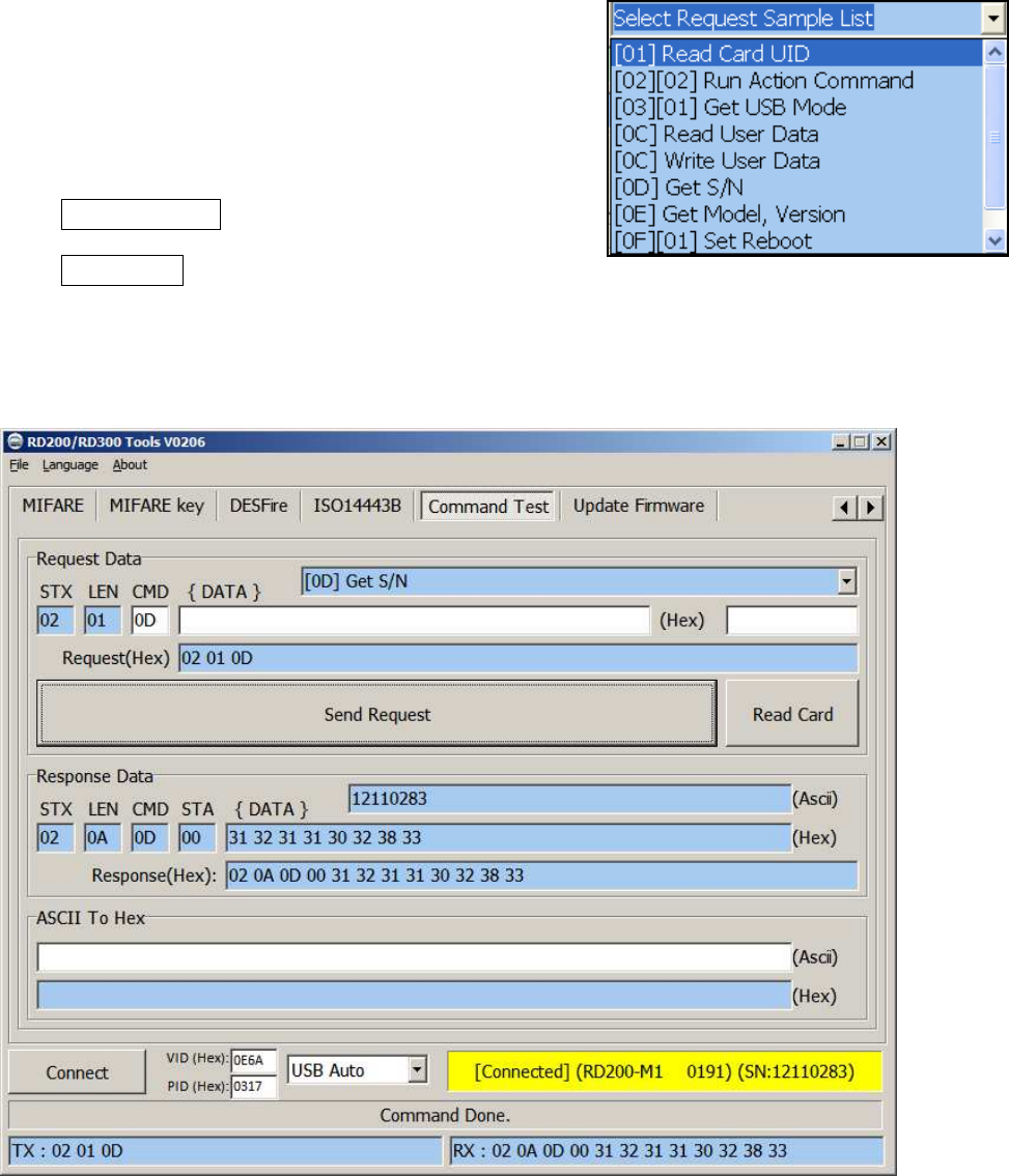
Command Test
This page provides several command examples, user can choose the example from the Request
Sample List, or directly input the CMD and {DATA} to test
the command.
1. Click Send Request to send command to reader,
Click Read Card to read card data.
2. The response data of the request command are all display on Response Data fields.
3. The bottom of screen function is a utility to convert ASCII characters to Hexadecimal.
21
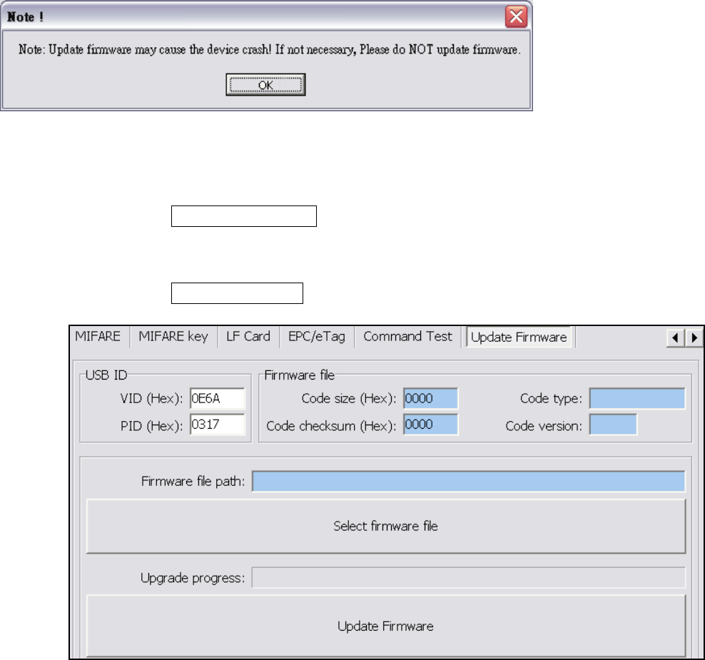
Firmware Update
Before update the firmware, system will pop up a warning message window.
The firmware update steps as below:
Step 1. Click Select firmware file
Step 2. Choose a firmware file (*.SYB)
Step 3. Click Update Firmware to finish the firmware update
22
FCC Statement
This device complies with Part 15 of the FCC Rules. Operation is subject to the following two
conditions: (1) This device may not cause harmful interference, and (2) this device must
accept any interference received, including interference that may cause undesired
operation.
This equipment has been tested and found to comply with the limits for a Class B digital
device, pursuant to Part 15 of the FCC Rules. These limits are designed to provide
reasonable protection against harmful interference in a residential installation. This
equipment generates, uses and can radiate radio frequency energy and, if not installed and
used in accordance with the instructions, may cause harmful interference to radio
communications. However, there is no guarantee that interference will not occur in a
particular installation. If this equipment does cause harmful interference to radio or
television reception, which can be determined by turning the equipment off and on, the user
is encouraged to try to correct the interference by one of the following measures:
- Reorient or relocate the receiving antenna.
- Increase the separation between the equipment and receiver.
- Connect the equipment into an outlet on a circuit different from that
to which the receiver is connected.
- Consult the dealer or an experienced radio/TV technician for help.
FCC Caution: Any changes or modifications not expressly approved by the party responsible
for compliance could void the user's authority to operate this equipment.
This transmitter must not be co-located or operating in conjunction with any other antenna or
transmitter.
Radiation Exposure Statement:
This equipment complies with FCC radiation exposure limits set forth for an uncontrolled
environment. This equipment should be installed and operated with minimum distance 20cm
between the radiator & your body.