SZ DJI TECHNOLOGY 201402241 DJI LIGHTBRIDGE User Manual LIGHTBRIDGE 2014 03 05B
SZ DJI TECHNOLOGY CO., LTD DJI LIGHTBRIDGE LIGHTBRIDGE 2014 03 05B
UserManual.wiki
>
SZ DJI TECHNOLOGY
>
201402241 User Manual
User Manual
Navigation menu
Upload a User Manual
Namespaces
Wiki Guide
HTML
PDF
Info
Views
User Manual
Discussion / Help
Navigation
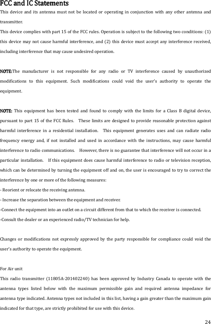
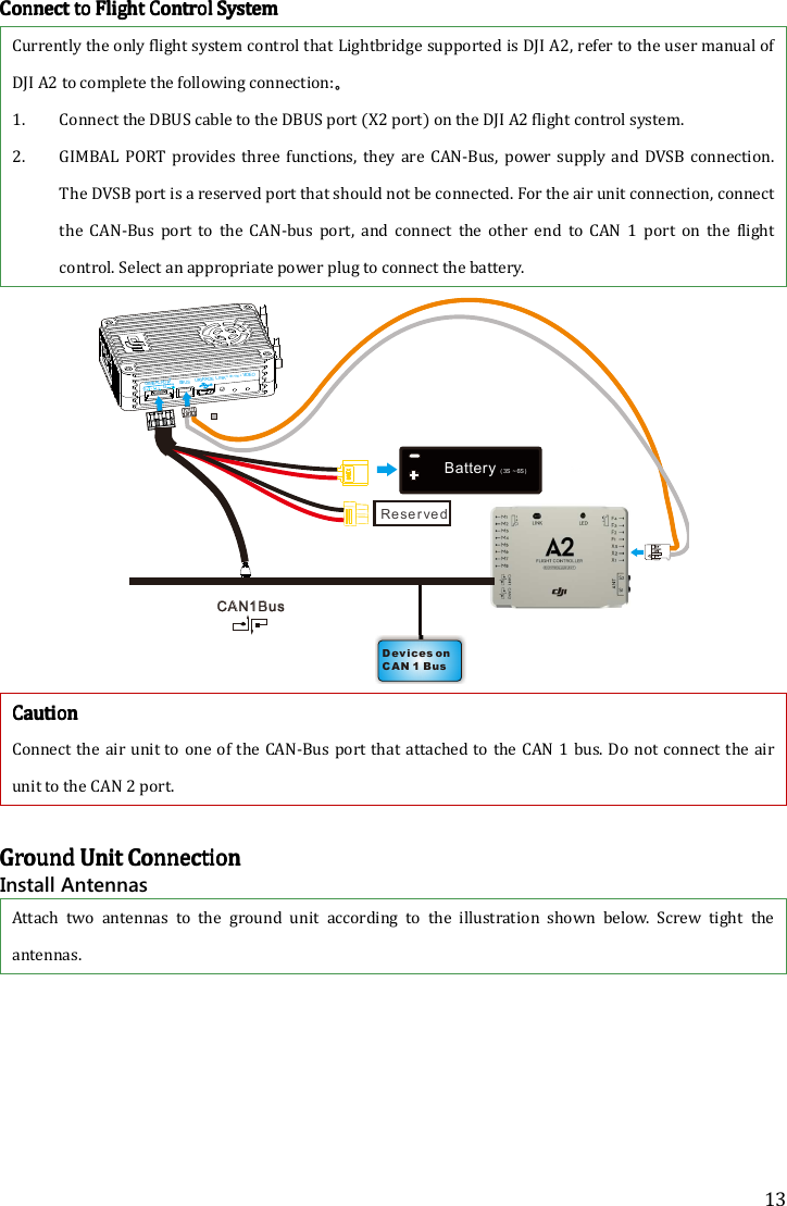
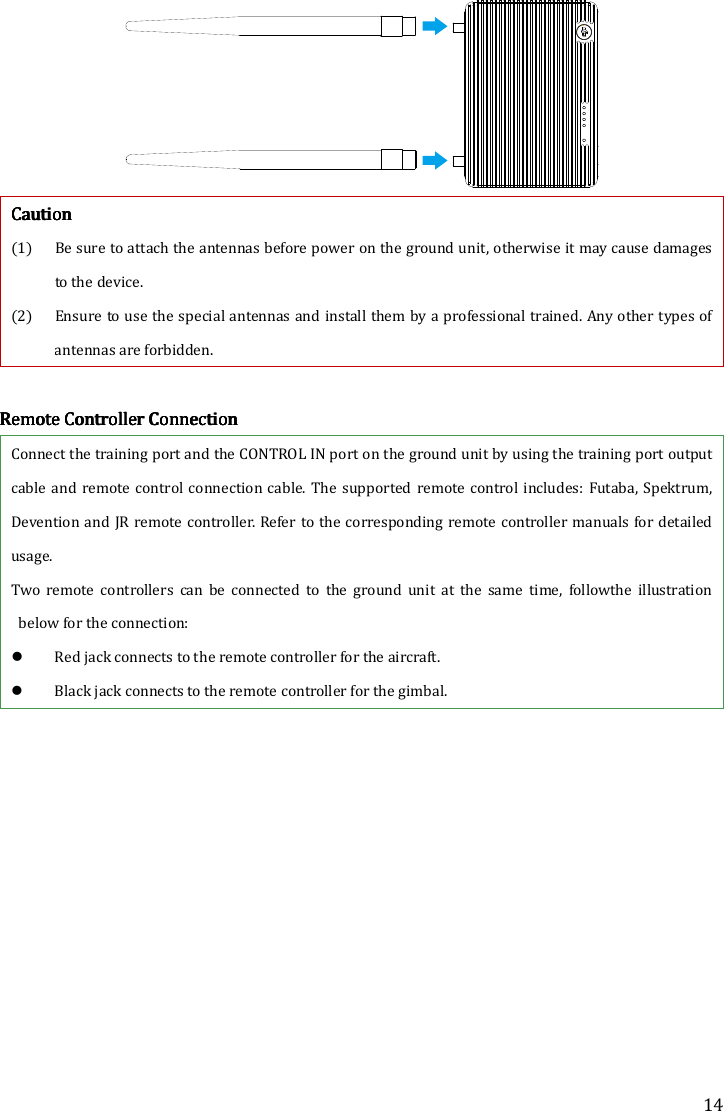
![7 IntroductionIntroductionIntroductionIntroduction Air Air Air Air UnitUnitUnitUnit Front viewFront viewFront viewFront view [1][1][1][1] GIMBAL PORTGIMBAL PORTGIMBAL PORTGIMBAL PORT Port functions shown as below: i. Power supply: (V+,V-) Connect to theon-board battery. ii. CAN-Bus: (L,H)Connect to the flight control system CAN-Bus port for obtaining flight control system OSD information. iii. DVSB: (G-,+)For DJI high end gimbal DVSB video streaming input. [2][2][2][2] DBUSDBUSDBUSDBUSportportportport Built-in receiver interface should be connected to DJI flight control system’s DBUS port usually locating at main controller labled X2. [3][3][3][3] UPGRADEUPGRADEUPGRADEUPGRADE portportportport Connect UPGRADEUPGRADEUPGRADEUPGRADE port to the USB port on a PC for firmware upgrade via theDJI Assistant Software. [4][4][4][4] LINKLINKLINKLINK buttonbuttonbuttonbutton Press the LINKLINKLINKLINK button to link the air unit with theand the ground unit. [5][5][5][5] CONTROLCONTROLCONTROLCONTROL indicatorindicatorindicatorindicator Transmitter link indicator is for display the communcationstatus between air and ground unit. IndicatorIndicatorIndicatorIndicator DescriptionDescriptionDescriptionDescription ActionActionActionAction No signal Power on the ground unit, and check the distance between ground unit and air unit. Signal is detected but not linked. Linking is required. Successfully linked. Proper functioning. [6][6][6][6] VIDEOVIDEOVIDEOVIDEO indicatorindicatorindicatorindicator Video indicator shows the transmission status of the vedio source. [ ]1[ ]2[ ]3[ ]4[ ]5[ ]6](https://usermanual.wiki/SZ-DJI-TECHNOLOGY/201402241/User-Guide-2219516-Page-7.png)
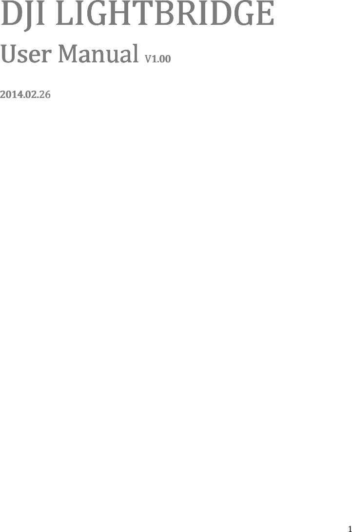
![8 IndicatorIndicatorIndicatorIndicator DescriptionDescriptionDescriptionDescription InstructionInstructionInstructionInstruction AV/HDMI signal is detected and proper functioning. Proper functioning. AV/HDMI signal is detected but transmission failed. Power cycle is required. No video source is detected. Check camera andconnection status. Top viewTop viewTop viewTop view [1][1][1][1] Ventilation Fan To ensure the fan works properly, do not obstruct the ventilation fan outlet when installing. SSSSide Viewide Viewide Viewide View [1][1][1][1] HDMIHDMIHDMIHDMI ININININ PortPortPortPort Connects to the HDMI input device. [2][2][2][2] AVAVAVAV PortPortPortPort Connects to the analog video input device. Tip: Select the appropriate port according to the video source format of the input device. Ground UnitGround UnitGround UnitGround Unit FFFFront Viewront Viewront Viewront View [ ]1[ ]1[ ]2](https://usermanual.wiki/SZ-DJI-TECHNOLOGY/201402241/User-Guide-2219516-Page-8.png)
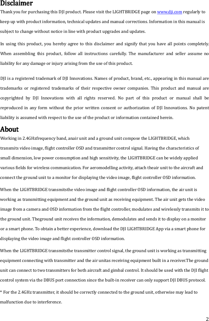
![9 [1][1][1][1] Power Adapter Port(11V~26V)Power Adapter Port(11V~26V)Power Adapter Port(11V~26V)Power Adapter Port(11V~26V) Connect the power adapter or a 3S~6S battery to this port to charge the built-in battery. If use a 3S~6S battery, the ground end comes with the protection function, which prevents the 3S~6S batter from over discharge. When the ground unit is connected with the external power adapter or battery, the built-in battery disables itself and switch to external power source. Beware of the input voltage range, do not exceed the operating range (11~26V). [2][2][2][2] UPGRADE PortUPGRADE PortUPGRADE PortUPGRADE Port Connect to a PC to upgrade the firmware by using the Assistance Software. [3][3][3][3] CONTROL INCONTROL INCONTROL INCONTROL IN PortPortPortPort Connect the training port and the CONTROL IN port on the ground unit using the training port output cable and remote control cable. [4][4][4][4] HDMIHDMIHDMIHDMIOUT PortOUT PortOUT PortOUT Port Connect to a HDMI supported monitor to view the video and OSD from the flight control system. [5][5][5][5] USBUSBUSBUSBPPPPortortortort Connect to a smart phone to view the video and OSD from the flight control system by using the DJI Lightbridge App. TTTTop Viewop Viewop Viewop View](https://usermanual.wiki/SZ-DJI-TECHNOLOGY/201402241/User-Guide-2219516-Page-9.png)
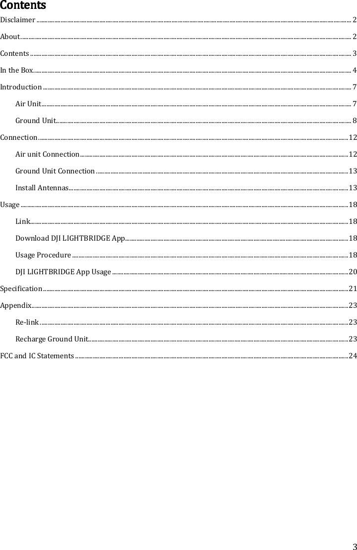
![10 [1][1][1][1] VVVVIDEOIDEOIDEOIDEOIIIIndicator ndicator ndicator ndicator Vedio transmission linkage indicator, used together with the air unit remote controller to reflect the connection status between the air unit and ground unit. IIIIndicatorndicatorndicatorndicator DDDDescriptionescriptionescriptionescription Signal detected from the air unit and ground unit works normally. Signal undetected from the air unit but ground unit works normally. [2][2][2][2] POWERPOWERPOWERPOWER IndicatorIndicatorIndicatorIndicator Dynamically shows the battery capacity of the ground unit. IIIIndicatorndicatorndicatorndicator BatteryBatteryBatteryBatteryCCCCapacityapacityapacityapacity 87.5%~100% 75%~87.5% 62.5%~75% 50%~62.5% 37.5%~50% 25%~37.5% 12.5%~25% 0%~12.5% =0%](https://usermanual.wiki/SZ-DJI-TECHNOLOGY/201402241/User-Guide-2219516-Page-10.png)
![11 Solid green Flashing green Off [3][3][3][3] Power Power Power Power ButtonButtonButtonButton Power on:Power on:Power on:Power on:Press the button once and hold to the button for more than 2 seconds to power on. Power off: Power off: Power off: Power off: Press the button once and press the button again to power off.... Show capacity: Show capacity: Show capacity: Show capacity: Press the button once to display the capacity of the battery.](https://usermanual.wiki/SZ-DJI-TECHNOLOGY/201402241/User-Guide-2219516-Page-11.png)
![15 TransmitterTransmitterTransmitterTransmitter ConfigurationConfigurationConfigurationConfiguration Refer to your own remote controller for reference. The below configuration process is based on Futaba T8FG as the example: 1. Switch off the RF option. The below procedure takes the Futaba T8FG as the example: a) Press and hold the [RTC] button to switch on the remote controller. b) Enter [POWR MODE] menu, select [RF OFF]. POWER MODE RANGE CHECK RF OFF RF ON c) RF indicator turns off and configuration success. 2. Set the [TRAVEL]value of each channels at the range within 100. The below procedure takes the Futaba T8FG as example: a) Double click the [LINK] button to enter [LINKAGE MENU], select [END POINT] option. b) Enter [END POINT] menu, set the [TRAVEL] value of each channels at the range with 100 as the below table shows:](https://usermanual.wiki/SZ-DJI-TECHNOLOGY/201402241/User-Guide-2219516-Page-15.png)
![16 END POINT 1/3 TRAVEL 1 AIL 135 100 100 135 2 ELE 135 100 100 135 3 THR 135 100 100 135 4RUD 135 100 100 135 CCCCautionautionautionaution In some cases (namely for Futaba T8J remote controller), even though the [TRAVEL] value has been set to 100, but the actual output value may exceeds 100. The inconsistent value can be observed out by checking the [SERVO] in the Linkage show as below (actual GUI may vary from the models). SERVO1 2 34 5 6 7 8-100 -100 +100 -100 -100 +0 +0 +0OFF DG1 DG2 To prevent this situation, you must double check that the actual [TRAVEL] value does not exceed 100,otherwise you should re-configure the value until the requirement of the value is met. Video ConnectionVideo ConnectionVideo ConnectionVideo Connection Both HDMI and USB port can output video to the device, however, the selection of the output option is mutually exclusive. Select the video output base on your video device. Connect HDMI supported monitor to HDMI OUT port in the ground unit for HDMI viewing. (Coming soon) Connect smart phone to USB port on ground unit using USB cable. Use the DJI Lightbridge One app to view video and OSD information from the flight control system in real time.。The below illustration uses the USB port connection as the example.](https://usermanual.wiki/SZ-DJI-TECHNOLOGY/201402241/User-Guide-2219516-Page-16.png)

![18 UUUUsagesagesagesage LLLLinkinkinkink Linking is completed when the Lightbridge is shipped. Start using the product according to the indicators. Download Download Download Download DJI DJI DJI DJI LIGHTBRIDGELIGHTBRIDGELIGHTBRIDGELIGHTBRIDGE AppAppAppApp Select one of these approaches to download the DJI LIGHTBRIDGE App. Downloading ApproachDownloading ApproachDownloading ApproachDownloading Approach Approach 1 Scan the QR card to obtain the downlaod address for DJI Lightbridge App. Install the DJI Lightbridge App onto the smart phone. Approach 2 Android User Access to the Internet and search“DJI Lightbridge” in the Google Play and install theDJI Lightbridge App onto the smart phone. Beware of the update notification from the DJI officialwebsite and the Google Play to obtain the latest version of DJI Lightbridge App. Supported Supported Supported Supported Smart phoneSmart phoneSmart phoneSmart phone Android(Version 4.1.2 or later) Samsung Galaxy S3,S4,Note2,Note3, etc. UUUUsage Proceduresage Proceduresage Proceduresage Procedure 1.1.1.1. Power on the air unit first then the ground unit, wait until the [POWERPOWERPOWERPOWER] indicator is solid on. 2.2.2.2. Observe the [VIDEOVIDEOVIDEOVIDEO] indicator on the ground unit is solid, follow by the [CONTROLCONTROLCONTROLCONTROL] indicator, and finally observe the flash green indicator for the [VIDEOVIDEOVIDEOVIDEO] that shows the ground unit and the air unit are communicating normally. 3.3.3.3. Launch the DJI Lightbirdge App on your smart phone. If the preview image appears on the smart phone then it means the system is working normally. 4.4.4.4. Real time OSD information is availablewhen the flight control system is working normally. NNNNoticeoticeoticeotice (1) Position the air unit antennas downward and the ground unit antennas upward and ensure there is no obstacle between the air unit antennas and ground unit antenna otherwise the transmission distance may be affected. (2) When the air unit is receiving signals, both the antennas stop transmitting signals, one of the antenna starts receiving signals. Both antennas resume transmitting signals when the receiving](https://usermanual.wiki/SZ-DJI-TECHNOLOGY/201402241/User-Guide-2219516-Page-18.png)
![20 DJI DJI DJI DJI LIGHTBRIDGELIGHTBRIDGELIGHTBRIDGELIGHTBRIDGE AppAppAppApp UsageUsageUsageUsage DJI LIGHTBRIDGE App can display OSD information feed by the flight control system. The OSD information is shown as below: [1] IOC Status ON:Enabled OFF:Disabled [2] Control mode of the flight control system [3] Ground unit power capacity [4] Air unit power capacity [5] Transmission status [6] Remote controller status [7] GPS satellite count [8] Air craft nose orientation [9] Aircraft altitude [10] Aircraft flight distance (distance between the current position and the recorded Go Home position, only display when GPS signal is normal and Go Home position is recorded, display N/A otherwise) [11] Vertical speed of the aircraft [12] Horizontal speed of the aircraft [13] Preview window [14] Set up](https://usermanual.wiki/SZ-DJI-TECHNOLOGY/201402241/User-Guide-2219516-Page-20.png)
![23 AAAAppendixppendixppendixppendix Re-link Follow the below instruction to re-link the air unit and the ground unit when the initial linking is failed. 1.1.1.1. Maintain a distance of 0.5m to 1m between the air unit and the ground unit, power on the air unit and then the ground unit. 2.2.2.2. Use a pin to press the [LINK] [LINK] [LINK] [LINK] button on the air unit. Press and hold on for 5 seconds then release. 3.3.3.3. When re-link is finished, The [CONTROL] [CONTROL] [CONTROL] [CONTROL] indicator on air unit turns solid green. Recharge Recharge Recharge Recharge GGGGround Uround Uround Uround Unitnitnitnit 1. Connect the plug adapter to the power adapter before attach the power adapter to the ground unit. Plug the power adapter to power outlet to start recharging. Or connect to a 3S~6S battery with the Battery charger cable. 2. [[[[PowerPowerPowerPower]]]] indicator shows green shows charging in process. 3. [Power] [Power] [Power] [Power] indicator turns off shows the charging is completed. Power outlet](https://usermanual.wiki/SZ-DJI-TECHNOLOGY/201402241/User-Guide-2219516-Page-23.png)