SZ DJI TECHNOLOGY 201402241 DJI LIGHTBRIDGE User Manual LIGHTBRIDGE 2014 03 05B
SZ DJI TECHNOLOGY CO., LTD DJI LIGHTBRIDGE LIGHTBRIDGE 2014 03 05B
User Manual
1
DJI
DJI DJI
DJI
LIGHTBRIDGE
LIGHTBRIDGELIGHTBRIDGE
LIGHTBRIDGE
User Manual
User Manual User Manual
User Manual V1.0
V1.0V1.0
V1.00
00
0
2014.0
2014.02014.0
2014.02.2
2.22.2
2.26
66
6

2
Disclaimer
DisclaimerDisclaimer
Disclaimer
Thank you for purchasing this DJI product. Please visit the LIGHTBRIDGE page on www.dji.com regularly to
keep up with product information, technical updates and manual corrections. Information in this manual is
subject to change without notice in line with product upgrades and updates.
In using this product, you hereby agree to this disclaimer and signify that you have all points completely.
When assembling this product, follow all instructions carefully. The manufacturer and seller assume no
liability for any damage or injury arising from the use of this product.
DJI is a registered trademark of DJI Innovations. Names of product, brand, etc., appearing in this manual are
trademarks or registered trademarks of their respective owner companies. This product and manual are
copyrighted by DJI Innovations with all rights reserved. No part of this product or manual shall be
reproduced in any form without the prior written consent or authorization of DJI Innovations. No patent
liability is assumed with respect to the use of the product or information contained herein.
About
AboutAbout
About
Working in 2.4GHzfrequency band, anair unit and a ground unit compose the LIGHTBRIDGE, which
transmits video image, flight controller OSD and transmitter control signal. Having the characteristics of
small dimension, low power consumption and high sensitivity, the LIGHTBRIDGE can be widely applied
various fields for wireless communication. For aeromodelling activity, attach theair unit to the aircraft and
connect the ground unit to a monitor for displaying the video image, flight controller OSD information.
When the LIGHTBRIDGE transmitsthe video image and flight controller OSD information, the air unit is
working as transmitting equipment and the ground unit as receiving equipment. The air unit gets the video
image from a camera and OSD information from the flight controller, modulates and wirelessly transmits it to
the ground unit. Theground unit receives the information, demodulates and sends it to display on a monitor
or a smart phone. To obtain a better experience, download the DJI LIGHTBRIDGE App via a smart phone for
displaying the video image and flight controller OSD information.
When the LIGHTBRIDGE transmitsthe transmitter control signal, the ground unit is working as transmitting
equipment connecting with transmitter and the air unitas receiving equipment built in a receiver.The ground
unit can connect to two transmitters for both aircraft and gimbal control. It should be used with the DJI flight
control system via the DBUS port connection since the built-in receiver can only support DJI DBUS protocol.
* For the 2.4GHz transmitter, it should be correctly connected to the ground unit, otherwise may lead to
malfunction due to interference.
3
Contents
ContentsContents
Contents
Disclaimer .................................................................................................................................................................................................... 2
About .............................................................................................................................................................................................................. 2
Contents ........................................................................................................................................................................................................ 3
In the Box ...................................................................................................................................................................................................... 4
Introduction ................................................................................................................................................................................................ 7
Air Unit ................................................................................................................................................................................................. 7
Ground Unit ........................................................................................................................................................................................ 8
Connection ................................................................................................................................................................................................. 12
Air unit Connection ....................................................................................................................................................................... 12
Ground Unit Connection ............................................................................................................................................................. 13
Install Antennas.............................................................................................................................................................................. 13
Usage ............................................................................................................................................................................................................ 18
Link ...................................................................................................................................................................................................... 18
Download DJI LIGHTBRIDGE App........................................................................................................................................... 18
Usage Procedure ............................................................................................................................................................................ 18
DJI LIGHTBRIDGE App Usage ................................................................................................................................................... 20
Specification .............................................................................................................................................................................................. 21
Appendix ..................................................................................................................................................................................................... 23
Re-link ................................................................................................................................................................................................ 23
Recharge Ground Unit.................................................................................................................................................................. 23
FCC and IC Statements .......................................................................................................................................................................... 24
4
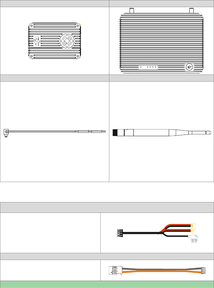
In the Box
In the BoxIn the Box
In the Box
M
MM
Modules
odulesodules
odules
Air
Air Air
Air
unit
unitunit
unit
×
××
×
1
11
1
Ground
GroundGround
Ground
unit
unitunit
unit
×1
×1×1
×1
Air
Air Air
Air
unit
unit unit
unit
antenna
antennaantenna
antenna
s
ss
s
×2
×2×2
×2
Ground
Ground Ground
Ground
unit
unit unit
unit
antenna
antennaantenna
antenna
s
ss
s
×2
×2×2
×2
Air
Air Air
Air un
unun
unit
itit
itcables
cablescables
cables
GIMBAL cable
GIMBAL cable GIMBAL cable
GIMBAL cable
×1
×1×1
×1
Connect the CAN
-
Bus connector to flight
control system for obtaining OSD
informationand the power connector to battery
for power supply. DVSB
connector
is reserved.
DBUS
DBUSDBUS
DBUS
cable
cable cable
cable
×1
×1×1
×1
Connect to
the flight control system
DBUS port
for
communication
.
AV
AVAV
AV
cable
cable cable
cable
×1
×1×1
×1
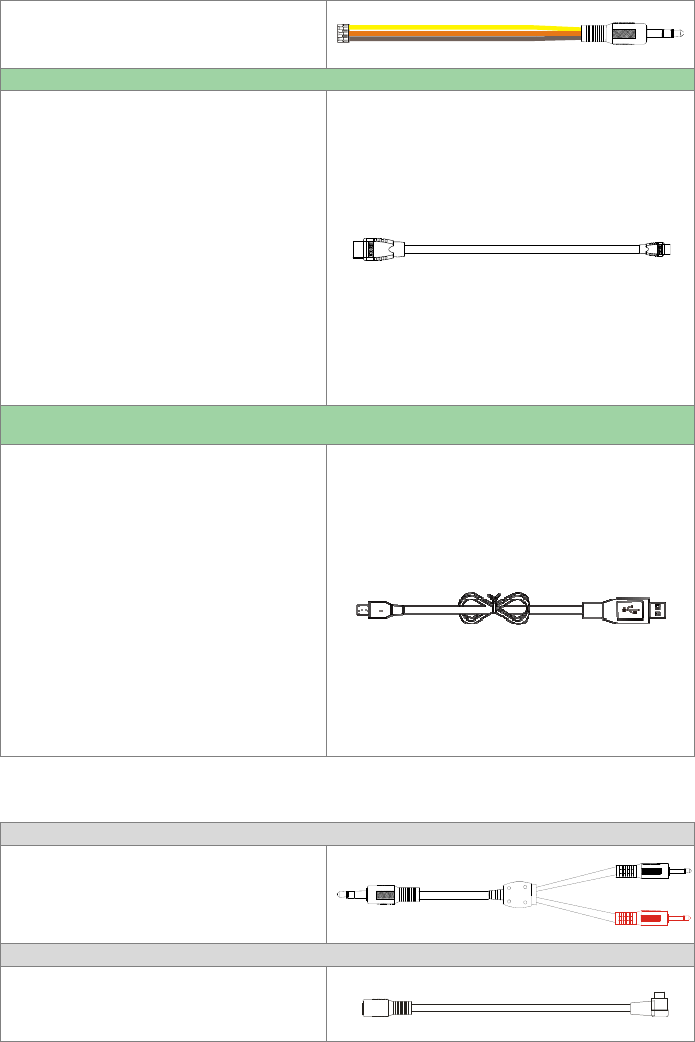
Connect to an a
nalog video signal
device.
HDMI
HDMIHDMI
HDMI
cable
cable cable
cable
×1
×1×1
×1
Connect to the HDMI port on the camera.
Micro
MicroMicro
Micro
-
--
-
USB
USBUSB
USB
cable
cable cable
cable
×1
×1×1
×1
Connect to a PC for firmware upgrade viathe
DJI Assistant Software.
Ground
Ground Ground
Ground unit
unitunit
unit
cables
cablescables
cables
Transmitter cable
Transmitter cable Transmitter cable
Transmitter cable
×1
×1×1
×1
Connect to the t
raining
port cable, with the red
port for aircraft control and the black port for
gimbal control.
Training
TrainingTraining
Training
port cable with
port cable with port cable with
port cable with
rectangular head
rectangular headrectangular head
rectangular head
×
××
×
1
11
1
,
, ,
,
Training
TrainingTraining
Training
port cable with circle
port cable with circleport cable with circle
port cable with circle
Connect to the
transmitter
’
s t
raining
port.
5
port cable with circle
port cable with circleport cable with circle
port cable with circle
head
headhead
head
×
××
×
1
11
1
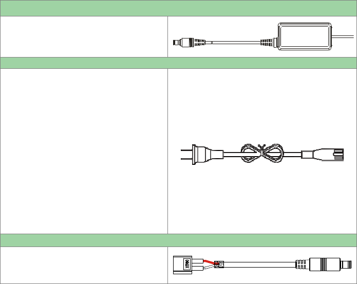
Charger
Charger Charger
Charger
×1
×1×1
×1
F
or charging the ground
unit
.
Charger cable
Charger cable Charger cable
Charger cable
×1
×1×1
×1
Connect the charger to a wall socket. Choose an
appropriate adapter for the wall socket.
Battery charger cable
Battery charger cableBattery charger cable
Battery charger cable
×1
×1×1
×1
Connect to a battery (3S~6S) for charging the
ground
unit
.
6
7
Introduction
IntroductionIntroduction
Introduction
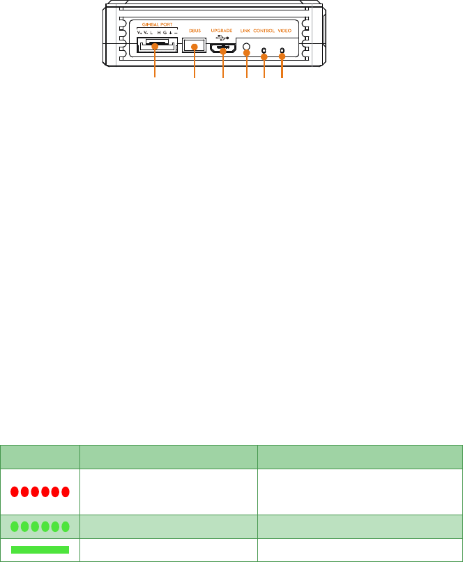
Air
Air Air
Air Unit
UnitUnit
Unit
Front view
Front viewFront view
Front view
[1]
[1][1]
[1] GIMBAL PORT
GIMBAL PORTGIMBAL PORT
GIMBAL PORT
Port functions shown as below:
i. Power supply: (V+,V-) Connect to theon-board battery.
ii. CAN-Bus: (L,H)Connect to the flight control system CAN-Bus port for obtaining flight control
system OSD information.
iii. DVSB: (G-,+)For DJI high end gimbal DVSB video streaming input.
[2]
[2][2]
[2] DBUS
DBUSDBUS
DBUSport
portport
port
Built-in receiver interface should be connected to DJI flight control system’s DBUS port usually
locating at main controller labled X2.
[3]
[3][3]
[3] UPGRADE
UPGRADEUPGRADE
UPGRADE
port
portport
port
Connect UPGRADE
UPGRADEUPGRADE
UPGRADE port to the USB port on a PC for firmware upgrade via theDJI Assistant Software.
[4]
[4][4]
[4] LINK
LINKLINK
LINK
button
buttonbutton
button
Press the LINK
LINKLINK
LINK button to link the air unit with theand the ground unit.
[5]
[5][5]
[5] CONTROL
CONTROLCONTROL
CONTROL
indicator
indicatorindicator
indicator
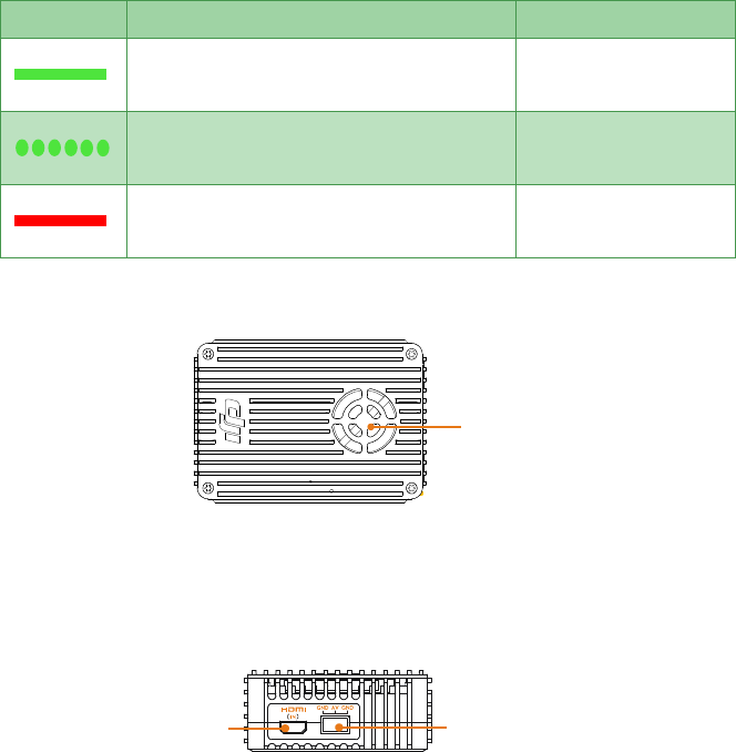
Transmitter link indicator is for display the communcationstatus between air and ground unit.
Indicator
IndicatorIndicator
Indicator
Description
DescriptionDescription
Description
Action
ActionAction
Action
No signal
Power on the
ground unit
, and check the
distance between
ground unit
and
air unit
.
Signal is detected
but not linked.
Link
ing
is required.
Successfully
linked
.
P
roper functioning
.
[6]
[6][6]
[6] VIDEO
VIDEOVIDEO
VIDEO
indicator
indicatorindicator
indicator
Video indicator shows the transmission status of the vedio source.
[ ]
1
[ ]
2
[ ]
3
[ ]
4
[ ]
5
[ ]
6
8
Indicator
IndicatorIndicator
Indicator
Description
DescriptionDescription
Description
Instruction
InstructionInstruction
Instruction
AV/
HDMI signal is detected and p
roper
functioning
.
P
roper functioning
.
AV/
HDMI signal is detected but transmission
failed.
Power cycle
is required.
No
video source is detected.
Check camera
andconnection
status
.
Top view
Top viewTop view
Top view
[1]
[1][1]
[1] Ventilation Fan
To ensure the fan works properly, do not obstruct the ventilation fan outlet when installing.
S
SS
Side View
ide Viewide View
ide View
[1]
[1][1]
[1] HDMI
HDMIHDMI
HDMI
IN
ININ
IN
Port
PortPort
Port
Connects to the HDMI input device.
[2]
[2][2]
[2] AV
AVAV
AV
Port
PortPort
Port
Connects to the analog video input device.
Tip: Select the appropriate port according to the video source format of the input device.
Ground Unit
Ground UnitGround Unit
Ground Unit
F
FF
Front View
ront Viewront View
ront View
[ ]
1
[ ]
1
[ ]
2
9
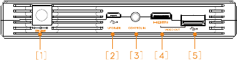
[1]
[1][1]
[1] Power Adapter Port(11V~26V)
Power Adapter Port(11V~26V)Power Adapter Port(11V~26V)
Power Adapter Port(11V~26V)
Connect the power adapter or a 3S~6S battery to this port to charge the built-in battery. If use a
3S~6S battery, the ground end comes with the protection function, which prevents the 3S~6S batter
from over discharge. When the ground unit is connected with the external power adapter or battery,
the built-in battery disables itself and switch to external power source. Beware of the input voltage
range, do not exceed the operating range (11~26V).
[2]
[2][2]
[2] UPGRADE Port
UPGRADE PortUPGRADE Port
UPGRADE Port
Connect to a PC to upgrade the firmware by using the Assistance Software.
[3]
[3][3]
[3] CONTROL IN
CONTROL INCONTROL IN
CONTROL IN
Port
PortPort
Port
Connect the training port and the CONTROL IN port on the ground unit using the training port output
cable and remote control cable.
[4]
[4][4]
[4] HDMI
HDMIHDMI
HDMIOUT Port
OUT PortOUT Port
OUT Port
Connect to a HDMI supported monitor to view the video and OSD from the flight control system.
[5]
[5][5]
[5] USB
USBUSB
USBP
PP
Port
ortort
ort
Connect to a smart phone to view the video and OSD from the flight control system by using the DJI
Lightbridge App.
T
TT
Top View
op Viewop View
op View
10
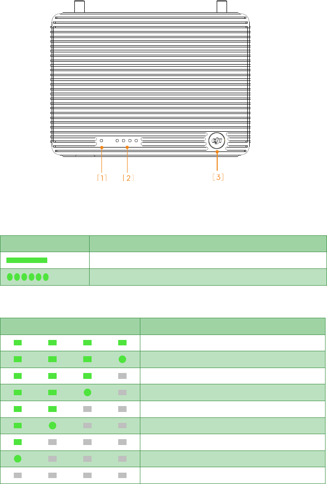
[1]
[1][1]
[1] V
VV
VIDEO
IDEOIDEO
IDEOI
II
Indicator
ndicator ndicator
ndicator
Vedio transmission linkage indicator, used together with the air unit remote controller to reflect the
connection status between the air unit and ground unit.
I
II
I
ndicator
ndicatorndicator
ndicator
D
DD
D
escription
escriptionescription
escription
Signal
detected
from the air unit
and ground unit works normally.
Signal undetected
from the air unit
but ground unit works normally.
[2]
[2][2]
[2] POWER
POWERPOWER
POWER
Indicator
IndicatorIndicator
Indicator
Dynamically shows the battery capacity of the ground unit.
I
II
I
ndicator
ndicatorndicator
ndicator
Battery
BatteryBattery
Battery
C
CC
C
apacity
apacityapacity
apacity
87.5%~100%
75%~87.5%
62.5%~75%
50%~62.5%
37.5%~50%
25%~37.5%
12.5%~25%
0%~12.5%
=
0%

11
Solid green
Flashing green
O
ff
[3]
[3][3]
[3] Power
Power Power
Power Button
ButtonButton
Button
Power on:
Power on:Power on:
Power on:Press the button once and hold to the button for more than 2 seconds to power on.
Power off:
Power off: Power off:
Power off: Press the button once and press the button again to power off.
..
.
Show capacity:
Show capacity: Show capacity:
Show capacity: Press the button once to display the capacity of the battery.
12
Connection
ConnectionConnection
Connection
Air
Air Air
Air unit
unitunit
unit
Connection
ConnectionConnection
Connection
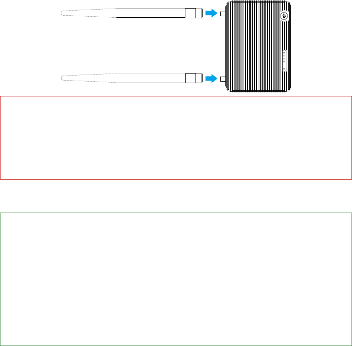
Install Antennas
Install AntennasInstall Antennas
Install Antennas
Insert the antennas to the position shown in the illustration below.
Ensure that you heard a ‘click’ sound
to confirm the antennas are in place.
Notice
NoticeNotice
Notice
(1) Install the antennas before the air unit is powered on.
(2) When in using, placed the antennas downward and keep it unobstructed to ensure the
transmission signal quality.
(3) Ensure to use the special antennas and install them by a professional trained. Any other types of
antennas are
forbidden.
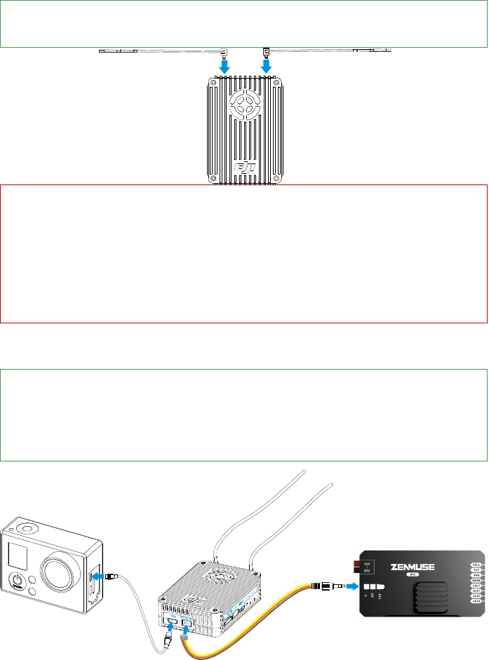
Video Source Con
Video Source ConVideo Source Con
Video Source Connection
nectionnection
nection
DJI Lightbridge supports both
the
HDMI and AV input. Refer to the
illustration
below for
connection.For HDMI input, connect the HDMI cable to the HDMI port on the camera.For AV input,
connect the AV cable to the AV output port on the camera. When using the DJI gimbal, connect to
the video output port on the GCU model. The illustration below use the DJI GCU as the example.
13
C
CC
Connect to Flight Control System
onnect to Flight Control Systemonnect to Flight Control System
onnect to Flight Control System
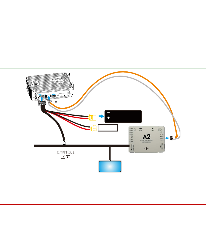
Currently the only flight system control that Lightbridge supported is DJI A2, refer to the
user manu
a
l of
DJI A2 to complete the following connection:。
1. Connect the DBUS cable to the DBUS port (X2 port) on the DJI A2 flight control system.
2. GIMBAL PORT provides three functions, they are CAN-Bus, power supply and DVSB connection.
The DVSB port is a reserved port that should not be connected. For the air unit connection, connect
the CAN-Bus port to the CAN-bus port, and connect the other end to CAN 1 port on the flight
control. Select an appropriate power plug to connect the battery.
D
BUS
LINK
CO
NTR
OL
V
IDEO
G
G
IM
BAL
P
OR
TUP
GRADE
V+
V-HL
D ev ices on
C A N 1 Bus
CA N1 B u s
Battery ( 3S ~ 6S )
Re se r ve d
Caution
CautionCaution
Caution
Connect the air unit to one of the CAN-Bus port that attached to the CAN 1 bus. Do not connect the air
unit
to the CAN 2 port
.
Ground Unit Connection
Ground Unit ConnectionGround Unit Connection
Ground Unit Connection
Install Antennas
A
ttach two antennas to the ground unit according to the
illustration shown below
.
Screw tight the
antennas.
14
C
CC
C
aution
autionaution
aution
(1) Be sure to attach the antennas before power on the ground unit, otherwise it may cause damages
to the device.
(2) Ensure to use the special antennas and install them by a professional trained. Any other types of
antennas are
forbidden.
R
RR
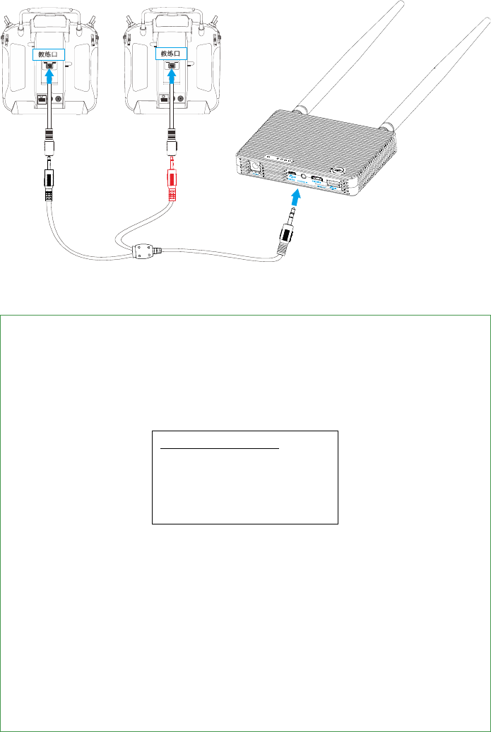
Remote Controller Connection
emote Controller Connectionemote Controller Connection
emote Controller Connection
Connect the training port and the CONTROL IN
port on the
ground unit
by using the training port output
cable and remote control connection cable. The supported remote control includes: Futaba, Spektrum,
Devention and JR remote controller. Refer to the corresponding remote controller manuals for detailed
usage.
Two remote controllers can be connected to the ground unit at the same time, followthe illustration
below for the connection:
Red jack connects to the remote controller for the aircraft.
Black jack connects to the remote controller for the gimbal.
15
Transmitter
TransmitterTransmitter
Transmitter
Configuration
ConfigurationConfiguration
Configuration
Refer to your own remote controller for reference. The below configuration process is based on Futaba
T8FG as the example:
1. Switch off the RF option. The below procedure takes the Futaba T8FG as the example:
a) Press and hold the [RTC] button to switch on the remote controller.
b) Enter [POWR MODE] menu, select [RF OFF].
POWER MODE
RANGE CHECK
RF OFF
RF ON
c) RF indicator turns off and configuration success.
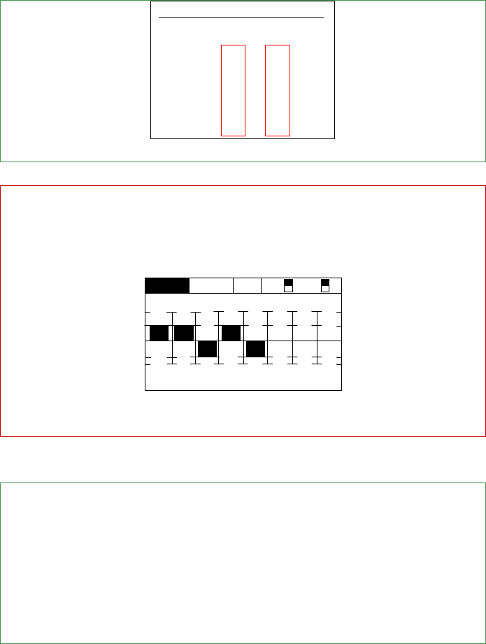
2. Set the [TRAVEL]value of each channels at the range within 100. The below procedure takes the
Futaba T8FG as example:
a) Double click the [LINK] button to enter [LINKAGE MENU], select [END POINT] option.
b) Enter [END POINT] menu, set the [TRAVEL] value of each channels at the range with 100 as
the below table shows:
16
END POINT 1/3
TRAVEL
1 AIL 135 100 100 135
2 ELE 135 100 100 135
3 THR 135 100 100 135
4RUD 135 100 100 135
C
CC
C
aution
autionaution
aution
In some cases (namely for Futaba T8J remote controller), even though the [TRAVEL] value has been set to
100, but the actual output value may exceeds 100. The inconsistent value can be observed out by
checking the [SERVO] in the Linkage show as below (actual GUI may vary from the models).
SERVO
1 2 34 5 6 7 8
-100 -100 +100 -100 -100 +0 +0 +0
OFF DG1 DG2
To prevent this situation, you must double check that the actual [TRAVEL] value does not exceed
100,otherwise you should re
-
configure the value until the requirement of the value is met.
Video Connection
Video ConnectionVideo Connection
Video Connection
Both
HDMI and USB port can output video to the device, however,
the selection of the output option is
mutually exclusive. Select the video output base on your video device.
Connect HDMI supported monitor to HDMI OUT port in the ground unit for HDMI viewing.
(Coming soon)
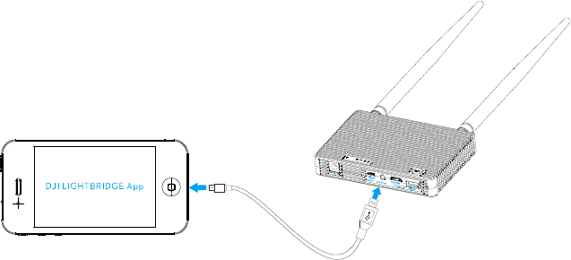
Connect smart phone to USB port on ground unit using USB cable. Use the DJI Lightbridge One app
to view video and OSD information from the flight control system in real time.。The below
illustration uses the USB port connection as the example.
17

18
U
UU
Usage
sagesage
sage
L
LL
Link
inkink
ink
Linking is completed when the Lightbridge is shipped. Start using the product according to the indicators.
Download
Download Download
Download DJI
DJI DJI
DJI LIGHTBRIDGE
LIGHTBRIDGELIGHTBRIDGE
LIGHTBRIDGE
App
AppApp
App
Select one of these approaches to download the DJI LIGHTBRIDGE App.
Downloading Approach
Downloading ApproachDownloading Approach
Downloading Approach
Approach 1
Scan the QR card to obtain the downlaod address for DJI Lightbridge App
.
Install the DJI Lightbridge App onto the
smart phone
.
A
pproach 2
Android
U
ser
Access to the Internet and search“DJI Lightbridge” in the Google Play
and
install the
DJI Lightbridge App onto the
smart phone
.
Beware of the update notification from the DJI
officialwebsite and the Google Play to obtain the latest
version of DJI Lightbridge App.
Supported
Supported Supported
Supported
Smart phone
Smart phoneSmart phone
Smart phone
Android
(
Version
4.
1.2
or later
)
Samsung
Galaxy S3
,
S4
,
Note2
,
Note3
, etc
.
U
UU
Usage Procedure
sage Proceduresage Procedure
sage Procedure
1.
1.1.
1.
Power on the air unit first then the ground unit, wait until the [
POWER
POWERPOWER
POWER
]
indicator is solid on.
2.
2.2.
2. Observe the [VIDEO
VIDEOVIDEO
VIDEO] indicator on the ground unit is solid, follow by the [CONTROL
CONTROLCONTROL
CONTROL] indicator, and
finally observe the flash green indicator for the [VIDEO
VIDEOVIDEO
VIDEO] that shows the ground unit and the air
unit are communicating normally.
3.
3.3.
3. Launch the DJI Lightbirdge App on your smart phone. If the preview image appears on the smart
phone then it means the system is working normally.
4.
4.4.
4.
Real time OSD information is
availablewhen the flight control system is working normally.
N
NN
N
otice
oticeotice
otice
(1) Position the air unit antennas downward and the ground unit antennas upward and ensure there is
no obstacle between the air unit antennas and ground unit antenna otherwise the transmission
distance may be affected.
(2) When the air unit is receiving signals, both the antennas stop transmitting signals, one of the
antenna starts receiving signals. Both antennas resume transmitting signals when the receiving

19
operation is completed.
(3) When the ground unit is receiving signals, both the antennas stop transmitting signals and start
receiving signals. When the ground unit is transmitting signals, the antennas stop receiving signals
and one of the antennas starts transmitting signals.
20
DJI
DJI DJI
DJI LIGHTBRIDGE
LIGHTBRIDGELIGHTBRIDGE
LIGHTBRIDGE
App
AppApp
App
Usage
UsageUsage
Usage
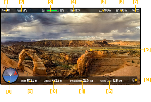
DJI LIGHTBRIDGE App can display OSD information feed by the flight control system. The OSD information is
shown as below:
[1] IOC Status
ON:Enabled
OFF:Disabled
[2] Control mode of the flight control system
[3] Ground unit power capacity
[4] Air unit power capacity
[5] Transmission status
[6] Remote controller status
[7] GPS satellite count
[8] Air craft nose orientation
[9] Aircraft altitude
[10] Aircraft flight distance (distance between the current position and the recorded Go Home position,
only display when GPS signal is normal and Go Home position is recorded, display N/A otherwise)
[11] Vertical speed of the aircraft
[12] Horizontal speed of the aircraft
[13] Preview window
[14] Set up

21
Specification
SpecificationSpecification
Specification
Performance Parameters
Performance ParametersPerformance Parameters
Performance Parameters
Transmission Distance(outdoor and
Transmission Distance(outdoor and Transmission Distance(outdoor and
Transmission Distance(outdoor and
unobstructed
unobstructedunobstructed
unobstructed
)
))
)
1.
2
Km
EIRP
EIRPEIRP
EIRP
10
0mW
Receiver
ReceiverReceiver
Receiver
Sensitivity
SensitivitySensitivity
Sensitivity
(
1%PER
1%PER1%PER
1%PER
)
-
101dBm
±
2dBm
Radio
RadioRadio
Radio
Frequency
FrequencyFrequency
Frequency(Air Unit)
(Air Unit)(Air Unit)
(Air Unit)
CH1
-
CH
8
CH1:2406.5MHz
CH2:2416.5MHz
CH3:2426.5MHz
CH4
:
2436.5MH
z
CH5:2446.5MHz
CH6:2456.5MHz
CH7:2466.5MHz
CH8
:
2476.5MH
z
Radio
RadioRadio
Radio
Frequency
FrequencyFrequency
Frequency(Ground Unit)
(Ground Unit)(Ground Unit)
(Ground Unit)
CH1
-
CH
36
CH1:2405.376MHz
CH2:2407.424MHz
CH3:2409.472MHz
CH4:2411.52MHz
CH5:2413.568MHz
CH6:2415.616MHz
CH7:2417.664MHz
CH8:2419.712MHz
CH9:2421.76MHz
CH10:2423.808MHz
CH11:2425.856MHz
CH12:2427.904MHz
CH13:2429.952MHz
CH14:2432MHz
CH15:2434.048MHz
CH16:2436.096MHz
CH17:2438.144MHz
CH18:2440.192MHz
CH19:2442.24MHz
CH20:2444.288MHz
CH21:2446.336MHz
CH22:2448.384MHz
CH23:2450.432MHz
CH24:2452.48MHz
CH25:2454.528MHz
CH26:2456.576MHz
CH27:2458.624MHz
CH28:2460.672MHz
CH29:2462.72MHz
CH30:2464.768MHz
CH31:2466.816MHz
CH32:2468.864MHz
CH33:2470.912MHz
CH34:2472.96MHz
CH35:2475.008MHz
CH
36
:
2477.056MH
z
Antenna Gain (Air Unit)
Antenna Gain (Air Unit)Antenna Gain (Air Unit)
Antenna Gain (Air Unit)
2.5dBi
4.68
Antenna Gain (Ground Unit)
Antenna Gain (Ground Unit)Antenna Gain (Ground Unit)
Antenna Gain (Ground Unit)
dBi

22
P
PP
P
hysical Parameters
hysical Parametershysical Parameters
hysical Parameters
Operating Temperature
Operating TemperatureOperating Temperature
Operating Temperature
-
10~50
o
C
Dimension (
Dimension (Dimension (
Dimension (
no
no no
no
antennas
antennasantennas
antennas
)
Air unit
:
68cm(
L
)X48cm(
W
)X21cm(
H
)
Ground unit
:
125cm(
L
)X90cm(
W
)X20cm(
H
)
Gross Weight
Gross WeightGross Weight
Gross Weight
(
no antennas
no antennasno antennas
no antennas
)
Air unit
:
71g
Ground unit
:
295g
Hardware Function
Hardware FunctionHardware Function
Hardware Function
s
ss
s
Supported
SupportedSupported
Supported
Antenna
Antenna Antenna
Antenna
connector
connectorconnector
connector
MMCX
Male
(
air unit
),
SMA
M
ale
(
ground unit
)
Air unit operating voltage
Air unit operating voltageAir unit operating voltage
Air unit operating voltage
3S~6S
Ground unit operating voltage
Ground unit operating voltageGround unit operating voltage
Ground unit operating voltage
3S~6S
Air unit operating
Air unit operating Air unit operating
Air unit operating
amperage
amperageamperage
amperage
700mA
±
20
mA(@12V)
Grou
GrouGrou
Grou
nd unit operating amperage
nd unit operating amperage nd unit operating amperage
nd unit operating amperage
600mA
±
10
mA
(@12V)
23
A
AA
Appendix
ppendixppendix
ppendix
Re-link
Follow the below instruction to re-link the air unit and the ground unit when the initial linking is failed.
1.
1.1.
1.
Maintain a distance
of
0.5m to 1m
between the air unit and the ground unit, power on the air unit
and then the ground unit.
2.
2.2.
2. Use a pin to press the [LINK]
[LINK] [LINK]
[LINK] button on the air unit. Press and hold on for 5 seconds then release.
3.
3.3.
3.
When re
-
link is finished, The
[CONTROL]
[CONTROL] [CONTROL]
[CONTROL]
indicator on air unit turns solid green.
Recharge
Recharge Recharge
Recharge G
GG
Ground U
round Uround U
round Unit
nitnit
nit
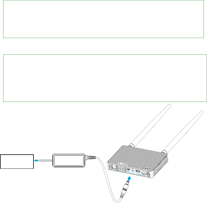
1.
C
onnect the plug adapter to
the power adapter before attach the power adapter to the gro
und unit
.
Plug the power adapter to power outlet to start recharging. Or connect to a 3S~6S battery with the
Battery charger cable.
2. [
[[
[Power
PowerPower
Power]
]]
] indicator shows green shows charging in process.
3.
[Power]
[Power] [Power]
[Power]
indicator turns off shows the charging is completed.
Power outlet
24
FCC and IC Statements
FCC and IC StatementsFCC and IC Statements
FCC and IC Statements
This device and its antenna must not be located or operating in conjunction with any other antenna and
transmitter.
This device complies with part 15 of the FCC rules. Operation is subject to the following two conditions: (1)
this device may not cause harmful interference, and (2) this device must accept any interference received,
including interference that may cause undesired operation.
NOTE:
NOTE:NOTE:
NOTE:The manufacturer is not responsible for any radio or TV interference caused by unauthorized
modifications to this equipment. Such modifications could void the user’s authority to operate the
equipment.
NOTE:
NOTE: NOTE:
NOTE: This equipment has been tested and found to comply with the limits for a Class B digital device,
pursuant to part 15 of the FCC Rules. These limits are designed to provide reasonable protection against
harmful interference in a residential installation. This equipment generates uses and can radiate radio
frequency energy and, if not installed and used in accordance with the instructions, may cause harmful
interference to radio communications. However, there is no guarantee that interference will not occur in a
particular installation. If this equipment does cause harmful interference to radio or television reception,
which can be determined by turning the equipment off and on, the user is encouraged to try to correct the
interference by one or more of the following measures:
- Reorient or relocate the receiving antenna.
- Increase the separation between the equipment and receiver.
-Connect the equipment into an outlet on a circuit different from that to which the receiver is connected.
-Consult the dealer or an experienced radio/TV technician for help.
Changes or modifications not expressly approved by the party responsible for compliance could void the
user’s authority to operate the equipment.
For Air unit
This radio transmitter (11805A-201402240) has been approved by Industry Canada to operate with the
antenna types listed below with the maximum permissible gain and required antenna impedance for
antenna type indicated. Antenna types not included in this list, having a gain greater than the maximum gain
indicated for that type, are strictly prohibited for use with this device.

25
Manufacturer
Model
Conn
ect Type
Maximum Gain
Impedance
INVAX System Technology Corp.
AN2400
-
06169GMX
MMCX Male
2.5 dBi
50 Ohm
For Ground unit
This radio transmitter (11805A-201402241) has been approved by Industry Canada to operate with the
antenna types listed below with the maximum permissible gain and required antenna impedance for
antenna type indicated. Antenna types not included in this list, having a gain greater than the maximum gain
indicated for that type, are strictly prohibited for use with this device.
Manufacturer
Model
Connector Type
Maximum Gain
Impedance
INVAX System Technology Corp.
AN2400
-
9297SM
SMA Male
4.68 dBi
50 Ohm
This device complies with Industry Canada licence-exempt RSS standard(s). Operation is subject to the
following two conditions: (1) this device may not cause interference, and (2) this device must accept any
interference, including interference that may cause undesired operation of the device.
Le présentappareilestconforme aux CNR d'Industrie Canada applicables aux appareils radio exempts de
licence. L'exploitationestautorisée aux deux conditions suivantes : (1) l'appareil ne doit pas produire de
brouillage, et (2) l'utilisateur de l'appareildoit accepter tout brouillageradioélectriquesubi, mêmesi le
brouillageest susceptible d'encompromettre le fonctionnement.
When using the device, ensure that the antenna of the device is as least 20 cm away from all persons.
Hereby, SZ DJI TECHNOLOGY CO. LTD declares that this device is in compliance with the essential
requirementsand other relevant provisions of Directive 1999/5/EC.