SZ DJI TECHNOLOGY HG8001501 RONIN-M User Manual 2
SZ DJI TECHNOLOGY CO., LTD RONIN-M 2
Contents
- 1. User Manual 1
- 2. User Manual 2
- 3. User Manual 3
- 4. User Manual 4
- 5. User Manual 5
User Manual 2
Ronin-M User Manual
14
© 2015 DJI. All Rights Reserved.
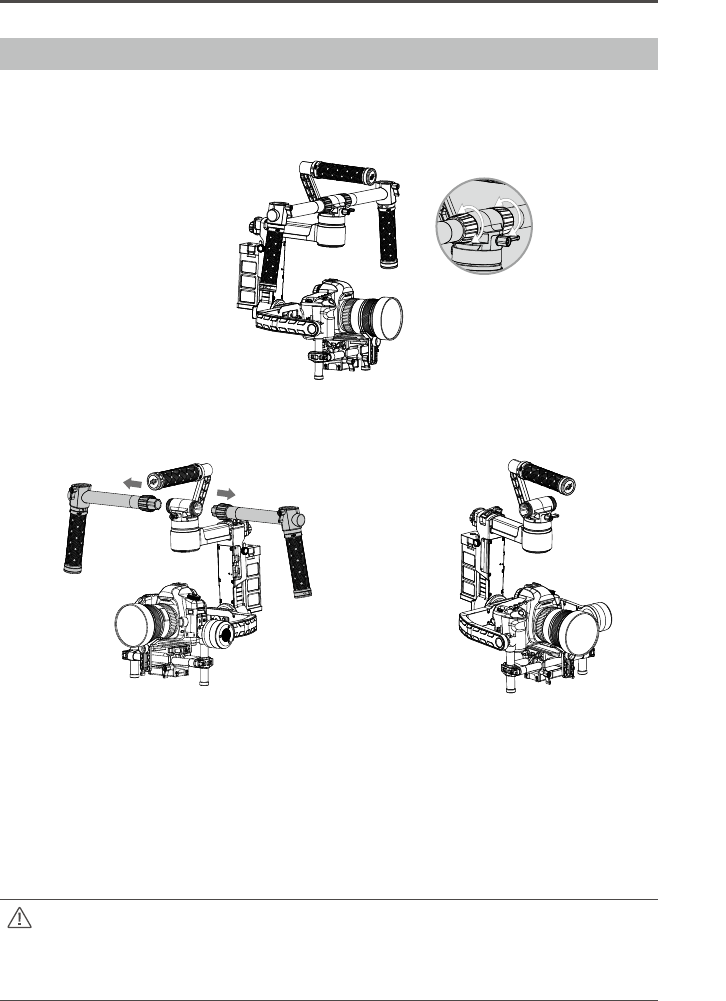
Handle Bar Adjustment
The customizable handle bar of the Ronin-M can be removed by following the steps below, if required.
1. Loosen the two screws as shown.
2. Remove the grip from the handle bar.
3. The resulting setup is shown below.
Balancing
To achieve the best performance from the Ronin-M, proper balancing is necessary and a must.
Accurate balance is critical in shots where the Ronin-M will be subjected to extreme movements or
accelerations (running, horseback riding, biking, car mounts, helicopters, etc.) Proper balance will also
offer a longer battery runtime. There are 3 axes that need to be accurately balanced prior to powering
the Ronin-M on and setting up the software.
The camera needs to be fully setup with all accessories prior to installing and balancing
the camera on the gimbal. If you are balancing the camera with a lens cap on, be sure to
remove the lens cap prior to balancing. Be sure whenever balancing the camera that the
Ronin-M’s power is turned off.
Ronin-M User Manual
© 2015 DJI. All Rights Reserved.
15
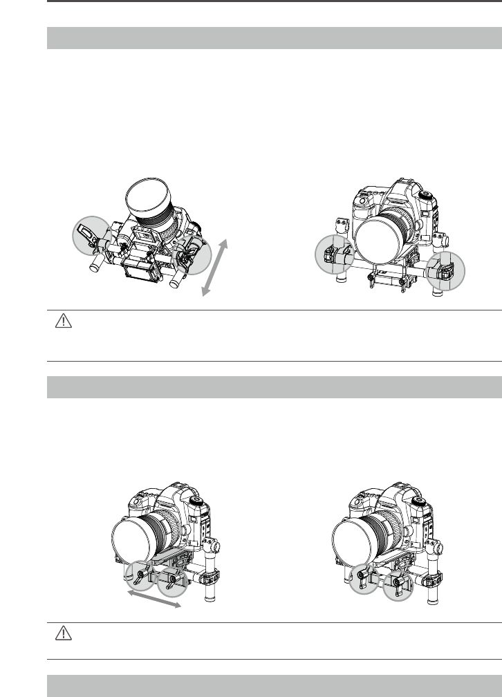
Step 1: Balancing the Vertical Tilt
To adjust the vertical balance, you will need to change the camera’s vertical position. Adjust the height
of the crossbar to achieve vertical tilt balance.
1. Rotate the Tilt Axis so that the camera lens is pointing skyward as much as your lens setup will
allow and loosen the two vertical adjustment tabs. Gently slide the camera mount crossbar forward
or backward until the camera remains pointing skyward when released.
2. Tighten the tabs and manually rotate the assembly simulating tilt to ensure there is no binding in the
tilt motor. When proper balance is achieved, you can rotate the camera to any tilt angle, and it will
stay in that position.
Ensure the measurement marks match up on either side of the vertical bars. If they do not
match up, the assembly could possibly be skewed higher or lower on one side, which would
cause the tilt motor to bind.
Step 2: Balancing the Roll Axis
Balancing the camera left-to-right on the Roll Axis is also required. When the proper left/right roll
balance is achieved, the camera will stay level.
1. Loosen the 2 lock-knobs to allow the camera and mounting plate to slide left and right. Slide the
camera left or right until the Roll Axis remains level.
2. Tighten the 2 Lock-knobs to lock the camera mounting plate in position.
Step3:BalancingtheTiltAxis
We also need to balance the camera fore and aft on the Tilt Axis. When the proper fore and aft tilt balance
is achieved, the camera will stay level when you remove your hand (hold the roll axis at the same time).
When adjusting the roll balancing position of the camera, only loosen the 2 lock-knobs a few
turns to allow the camera base to slide. Do not loosen the lock-knobs excessively.