SZ DJI TECHNOLOGY TP14061504 DJI MATRICE 100 User Manual
SZ DJI TECHNOLOGY CO., LTD DJI MATRICE 100 Users Manual
UserManual.wiki
>
SZ DJI TECHNOLOGY
>
TP14061504 User Manual
Users Manual
Navigation menu
Upload a User Manual
Namespaces
Wiki Guide
HTML
PDF
Info
Views
User Manual
Discussion / Help
Navigation


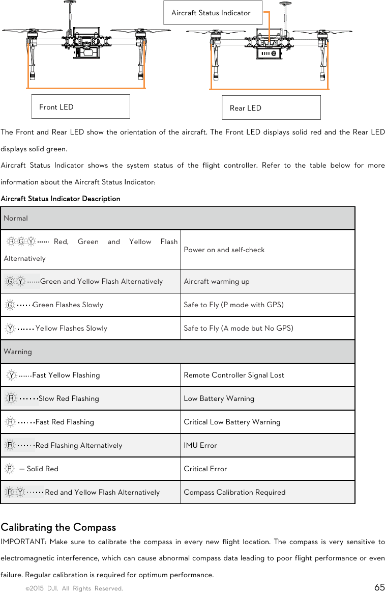
![©2015 DJI. All Rights Reserved. 26 Reserved Ports Description There are five kinds of ports reserved on the center frame. Connect your own devices to them. [1] XT30 Port [2] XT60 Port [3] GPS CAN Port [4] CAN1 Port [5] UART Port XT30 Ports and XT60 Ports There are three XT30 ports and one XT60 port reserved on the center frame. Supply power for your own devices by connecting them to these reserved ports. Use the XT30-XT60 cable if needed. Identify the positive and negative terminals of each port when connecting. The specifications of these four reserved ports are as shown below: Output Voltage Range 20 ~ 26.1 V Max. Persistent Output Current 10 A The total current of the one XT60 port and the three XT30 ports should not exceed 10 A. 5 431 21145Aircraft Nose Aircraft Nose](https://usermanual.wiki/SZ-DJI-TECHNOLOGY/TP14061504/User-Guide-2638073-Page-26.png)
![©2015 DJI. All Rights Reserved. 27 CAN Ports and UART Ports There is one GPS CAN port, two CAN1 ports (5-pin), and two UART ports (6-pin) reserved on the center frame. You can connect other devices to these ports, as required. The pin definitions of the CAN1 port and the UART port are as shown below: CAN1 Port (with a white dot beside pin 1): [1] GND [2] CANL [3] CANH [4] GND [5] VCC 7.4V UART Port (with a white dot beside pin 1): [1] UART TXD [2] UART RXD [3] GND [4] CANL [5] CANH [6] VCC 6 V](https://usermanual.wiki/SZ-DJI-TECHNOLOGY/TP14061504/User-Guide-2638073-Page-27.png)


![©2015 DJI. All Rights Reserved. 41 Remote Controller Diagram [1] Antennas Relays aircraft control and video signal. [2] Mobile Device Holder Mounting place for your mobile device. [3] Control Stick Controls aircraft orientation. [4] Return Home (RTH) Button Press and hold the button to initiate Return to Home (RTH). [5] RTH LED Circular LED around the RTH button displays RTH status. [6] Battery Level LEDs Displays the current battery level. [7] Status LED Displays the power status. [8] Power Button Used to power on or power off the remote controller.](https://usermanual.wiki/SZ-DJI-TECHNOLOGY/TP14061504/User-Guide-2638073-Page-41.png)
![©2015 DJI. All Rights Reserved. 42 [9] Camera Settings Dial Turn the dial to adjust camera settings. Only functions when the remote controller is connected to a mobile device running the DJI Pilot app. [10] Playback Button Playback the captured images or videos. [11] Shutter Button Press to take a photo. If in burst mode, the set number of photos will be taken with one press. [12] Flight Mode Switch Used to switch between P, A and F mode. [13] Video Recording Button Press to start recording video. Press again to stop recording. [14] Gimbal Dial Use this dial to control the tilt of the gimbal. [15] Micro-USB Port For connecting the remote controller to your computer. [16] Mini-HDMI Port Connect an HD compatible monitor to this port to get a live HD video preview of what the camera sees. [17] CAN Bus Port Reserved for future use. [18] USB Port Connect to mobile device to access all of the DJI Pilot app controls and features.](https://usermanual.wiki/SZ-DJI-TECHNOLOGY/TP14061504/User-Guide-2638073-Page-42.png)
![©2015 DJI. All Rights Reserved. 43 [19] GPS Module Used to pinpoint the location of the remote controller. [20] Back Left Button Customizable button in DJI Pilot app. [21] Power Port Connect to a power source to charge the remote controller’s internal battery. [22] Back Right Button Customizable button in DJI Pilot app. Remote Controller Operations Powering On and Off the Remote Controller The M100 remote controller is powered by a 2S rechargeable battery with a capacity of 6000mAh. The battery level is indicated by the Battery Level LEDs on the front panel. Follow the steps below to power on your remote controller: 1. When powered off, press the Power Button once and the Battery Level LEDs will display the current battery level. 2. Then, press and hold the Power Button to power on the remote controller. 3. The Remote Controller will beep when it powers on. The Status LED will blink green (slave remote controller blinks solid purple) rapidly, indicating that the remote controller is linking to the aircraft. The Status LED will show a solid green light when linking is completed. 4. Repeat step 2 to power off the remote controller after finish using it.](https://usermanual.wiki/SZ-DJI-TECHNOLOGY/TP14061504/User-Guide-2638073-Page-43.png)
![©2015 DJI. All Rights Reserved. 44 Charging Remote Controller Charge the remote controller via supplied charger. Controlling Camera Shoot videos or images and adjust camera settings via the Shutter Button, Camera Settings Dial, Playback Button and Video Recording Button on the remote control. [1] Camera Settings Dial Turn the dial to quickly adjust camera settings such as ISO and shutter speed without letting go of the remote controller. Move the dial button to left or right to view the pictures or videos in playback mode. [2] Playback Button Press to view images or videos that have already been captured. [3] Shutter Button Press to take a photo. If burst mode is activated, multiple photos will be taken with a single press. [4] Recoding Button Press once to start recording video, then press again to stop recording. Controlling Aircraft This section explains how to use the various features of the remote controller. The Remote Controller is set to Mode 2 by default. Stick Neutral/ mid point: Control sticks of the Remote Controller are placed at the central position. Move the Stick: The control stick is pushed away from the central position.](https://usermanual.wiki/SZ-DJI-TECHNOLOGY/TP14061504/User-Guide-2638073-Page-44.png)
![©2015 DJI. All Rights Reserved. 57 DJI Pilot App Use this app to control the gimbal, camera and other features of your flight system. (A DJI ZENMUSE X3 Gimbal with Camera is required when using gimbal and camera functions.) The app also comes with Map, Store a User Center, for configuring your aircraft and sharing your content with friends. It is recommended that you use a tablet for the best experience. When connecting to the aircraft for the first time, ensure your mobile device has access to the internet, and follow the instructions within the app. Camera The Camera page contains a live HD video feed from the camera (A DJI ZENMUSE X3 gimbal and camera is required). You can also configure various camera parameters from the Camera page. [1] Flight Mode](https://usermanual.wiki/SZ-DJI-TECHNOLOGY/TP14061504/User-Guide-2638073-Page-57.png)
![©2015 DJI. All Rights Reserved. 58 : The text next to this icon indicates the current flight mode. Tap to enter MC (Main Controller) settings. Modify flight limits, perform compass calibration, and set the gain values on this screen. [2] GPS Signal Strength : This icon shows the current strength of GPS signals. Green bars indicates adequate GPS strength. [3] System Status : This icon shows current aircraft system status, such as GPS signal health. [4] Battery Level Indicator : The battery level indicator dynamically displays the battery level. The color zones on the battery level indicator represent different battery levels. [5] Remote Controller Signal : This icon shows the strength of remote controller signal. [6] HD Video Link Signal Strength : This icon shows the HD video downlink signal strength between the aircraft and the remote controller. [7] Battery Level : This icon shows the current Intelligent Flight Battery level. Tap to enter battery information menu, set the various battery warning thresholds and view the battery warning history in this page. [8] General Settings : Tap this icon to enter General Settings page. Select parameter units, reset the camera, enable the quick view feature, adjust the gimbal roll value and toggle flight route display on this page. [9] Camera Operation Bar Exposure Lock : Tap to enable or disable the camera exposure lock. Function : Tap to adjust camera settings, such as video format and digital filters. Shutter : Tap this button to take a single photo. Record : Tap once to start recording video, then tap again to stop recording. You can also press the Video Recording Button on the remote controller, which has the same function.](https://usermanual.wiki/SZ-DJI-TECHNOLOGY/TP14061504/User-Guide-2638073-Page-58.png)
![©2015 DJI. All Rights Reserved. 59 Playback : Tap to enter playback page. You can preview photos and videos as soon as they are captured. Camera Settings and Shooting Mode : Tap to enter the Camera Settings page and switch from camera shooting mode from manual to auto. [10] Map Display the flight path of the current mission. Tap to switch from the Camera GUI to the Map GUI. [11] Flight Telemetry Flight Parameters: Height: Vertical distance from home point. Distance: Horizontal distance from home point. Vertical Speed: Vertical flying speed. Horizontal Speed: Horizontal flying speed. Flight Attitude and Radar Function: Flight attitude is indicated by the flight attitude icon. (1) The red arrow shows which direction the aircraft is facing. (2) Light blue and dark blue areas indicate pitch. (3) Pitching of the boundary between light blue and dark blue area shows roll angle. [12] Home Point Settings : Tap this button to reset the current home point. You may choose to set the aircraft take-off location, the remote controller’s current position, or the aircraft’s current position as the Home Point. [13] Return to Home (RTH) : Initiate RTH home procedure. Tap to have the aircraft return to the latest home point.](https://usermanual.wiki/SZ-DJI-TECHNOLOGY/TP14061504/User-Guide-2638073-Page-59.png)
![©2015 DJI. All Rights Reserved. 60 [14] Gimbal Operation Mode Refer to “DJI ZENMUSE X3 Gimbal with Camera” under “Appendix” (P76) for more information. [15] Auto Takeoff/Landing : Tap to initiate auto takeoff or landing. [16] Back : Tap to return to the main GUI. Map User can view the current flight route in a larger map view in this page. You can also perform Auto take-off and Landing in the page. Ensure your mobile device has access to the Internet. Due to the map data required, Wi-Fi connection is recommended. Internet access is required to cache the map, if Wi-Fi is unavailable, mobile data service is required. Academy Download user manual, view online videos. Also you can use the flight simulator to practice your flight skills. User Center You can sync the picture and videos to the mobile device, view the flight records and check your DJI account status in the User Center. Use the DJI registered account to login to the User Center.](https://usermanual.wiki/SZ-DJI-TECHNOLOGY/TP14061504/User-Guide-2638073-Page-60.png)