SZ DJI TECHNOLOGY TP14061504 DJI MATRICE 100 User Manual
SZ DJI TECHNOLOGY CO., LTD DJI MATRICE 100 Users Manual
Users Manual
©2015 DJI. All Rights Reserved. 1
DJI Matrix 100
User Manual
V 1.0
2015.5
www.dji.com
©2015 DJI. All Rights Reserved. 2
Using this manual
Legend
Warning Important Hints and Tips Reference
Before Flight
The following tutorials and manuals have been produced to ensure you to make full use of your M100.
1. Safety Guidelines and Disclaimer
2. M100 User Manual
3. In the Box
4. Intelligent Flight Battery Safety Guidelines
Reading the
Safety Guidelines and Disclaimer
before flight is recommended. Refer to this manual for more
comprehensive information.
Download the DJI Pilot app
Download and install the DJI Pilot app before use. Scan the QR code or visit
“http://m.dji.net/djipilot” to download the app.
For the best experience, use mobile device with Android V 4.1.2 or above. Requires iOS 8.0 or later.

©2015 DJI. All Rights Reserved. 3
Warnings
When flying, the rotating propellers may cause serious damage and injury. Please fly safely at all times.
Assembly Warnings
(1) Ensure that all parts are installed before inserting the Intelligent Flight Battery.
(2) Use a bracket to mount the GPS module onto the center frame to avoid interference with the power
board.
(3) Ensure frame arms are mounted correctly.
(4) Do not remove any glued-in screws.
(5) Screws that already have blue glue can be used once without thread locker. On other occasions, apply
appropriate thread locker first.
Flight Warnings
(1) ESCs are not waterproof, please do not fly in rain or snow.
(2) Ensure all parts are in good condition before each flight. Do not fly with worn or broken parts.
(3) Ensure propellers and motors are installed correctly before flying.
(4) Ensure all cables are secure before every flight.
(5) When flying, maintain a safe distance away from people, buildings, high voltage power lines, tall trees,
water and other hazards.
(6) Use only DJI TB47D/TB48D Intelligent Flight Batteries as the power supply.
(7) Do not overload the system.
(8) Do not get close to or touch motors or propellers when they are spinning, as this can cause serious injury.
(9) Disconnect the battery and remove the camera during transportation to avoid damage or injury.
(10) Only use compatible DJI parts.
If you encounter any problems or if you have any questions, please contact your local DJI authorized dealer or DJI
Support.
DJI Support Website:
www.dji.com/support
©2015 DJI. All Rights Reserved. 4
Contents
Using this manual ......................................................................................................................................................................................................... 2
Legend .................................................................................................................................................................................................................... 2
Before Flight ........................................................................................................................................................................................................ 2
Download the DJI Pilot app .......................................................................................................................................................................... 2
Warnings .......................................................................................................................................................................................................................... 3
Contents .......................................................................................................................................................................................................................... 4
Profile ................................................................................................................................................................................................................................ 6
In The Box ....................................................................................................................................................................................................................... 7
Checking Frame Arms (with the Landing Gear) ............................................................................................................................................ 11
Checking the Center Frame ................................................................................................................................................................................... 11
Mounting Frame Arms .............................................................................................................................................................................................. 13
Mounting the Battery Compartment and Wiring ......................................................................................................................................... 16
Recommended Mounting Position (under the center frame) ....................................................................................................... 16
Optional Mounting Position (on the center frame) ........................................................................................................................... 18
Wiring .................................................................................................................................................................................................................... 19
Mounting Expansion Bays ...................................................................................................................................................................................... 22
Mounting the GPS Module ................................................................................................................................................................................... 24
Reserved Ports Description ................................................................................................................................................................................. 26
XT30 Ports and XT60 Ports ...................................................................................................................................................................... 26
CAN Ports and UART Ports ........................................................................................................................................................................ 27
Attaching Propellers .................................................................................................................................................................................................28
Propeller Safety ................................................................................................................................................................................................28
Installation ...........................................................................................................................................................................................................28
Mounting the Gimbal (Optional) ........................................................................................................................................................................ 30
Using the DJI Intelligent Flight Battery .......................................................................................................................................................... 34
Introduction ....................................................................................................................................................................................................... 34
DJI Intelligent Flight Battery Functions ................................................................................................................................................ 34
Using the Battery .............................................................................................................................................................................................35
Using the Remote Controller .............................................................................................................................................................................. 39
Remote Controller Profile .......................................................................................................................................................................... 39
Preparing Remote Controller .................................................................................................................................................................... 39
Remote Controller Diagram ........................................................................................................................................................................ 41
Remote Controller Operations ................................................................................................................................................................. 43
©2015 DJI. All Rights Reserved. 5
Remote Controller Status LED ................................................................................................................................................................. 47
Linking the Remote Controller ................................................................................................................................................................. 48
Remote Controller Compliance Version .............................................................................................................................................. 49
Return to Home (RTH) and Dynamic Home Point ...................................................................................................................................... 50
Return to Home (RTH) .................................................................................................................................................................................. 50
Dynamic Home Point ...................................................................................................................................................................................... 52
Using the Matrix PC Assistant .............................................................................................................................................................................53
Using the SDK ............................................................................................................................................................................................................ 56
DJI Pilot App ................................................................................................................................................................................................................57
Camera .................................................................................................................................................................................................................57
Map ....................................................................................................................................................................................................................... 60
Academy ............................................................................................................................................................................................................. 60
User Center ....................................................................................................................................................................................................... 60
Flight ................................................................................................................................................................................................................................. 61
Flight Environment Requirements ............................................................................................................................................................ 61
Flight Limits and Flight Restriction Area ................................................................................................................................................ 61
Preflight Checklist .......................................................................................................................................................................................... 64
Flight Status Indicator................................................................................................................................................................................... 64
Calibrating the Compass ............................................................................................................................................................................. 65
Auto Take-off and Auto Landing.............................................................................................................................................................. 67
Starting/Stopping the Motors ................................................................................................................................................................... 67
Flight Test .......................................................................................................................................................................................................... 68
Appendix ...................................................................................................................................................................................................................... 69
Specifications .................................................................................................................................................................................................... 69
Aircraft Status Indicator Description ...................................................................................................................................................... 72
DJI ZENMUSE X3 Gimbal with Camera ................................................................................................................................................73
Compliance Information .............................................................................................................................................................................. 78
©2015 DJI. All Rights Reserved. 6
Profile
The M100 is a professional quad-rotor flying platform. It has modular hardware, and is an open platform for
developers to expand and build upon. The next generation flight controller system provides a more stable flight
experience. A low latency HD video downlink is powered by an enhanced version of the DJI Lightbridge system.
When used together with the DJI ZENMUSE X3 camera and gimbal, users can control the camera and gimbal via
the buttons and dials on the remote controller. A 4500 mAh DJI Intelligent Flight Battery employs new battery cells
and a battery management system. The expandable structure design of the center frame makes it easy to mount
other devices for more functions and a greater flight experience. Users can control the flying platform via the
convenient API provided by the open DJI SDK to build specialized flying solutions.
©2015 DJI. All Rights Reserved. 7
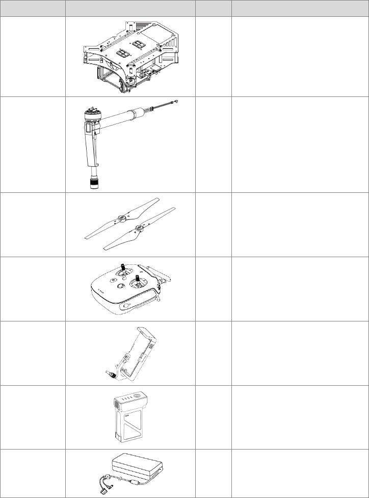
In The Box
Standard Package
Name Diagram Qty. Description
Center Frame 1 With Battery Compartment
Frame Arm 4 With Landing Gear
Quick-Release
Propellers (Pair) 3
Remote
Controller 1
Mobile Device
Holder 1
Intelligent Flight
Battery
1 Model: TB47D
Battery Charger 1 To charge the remote controller
battery and Intelligent Flight Battery
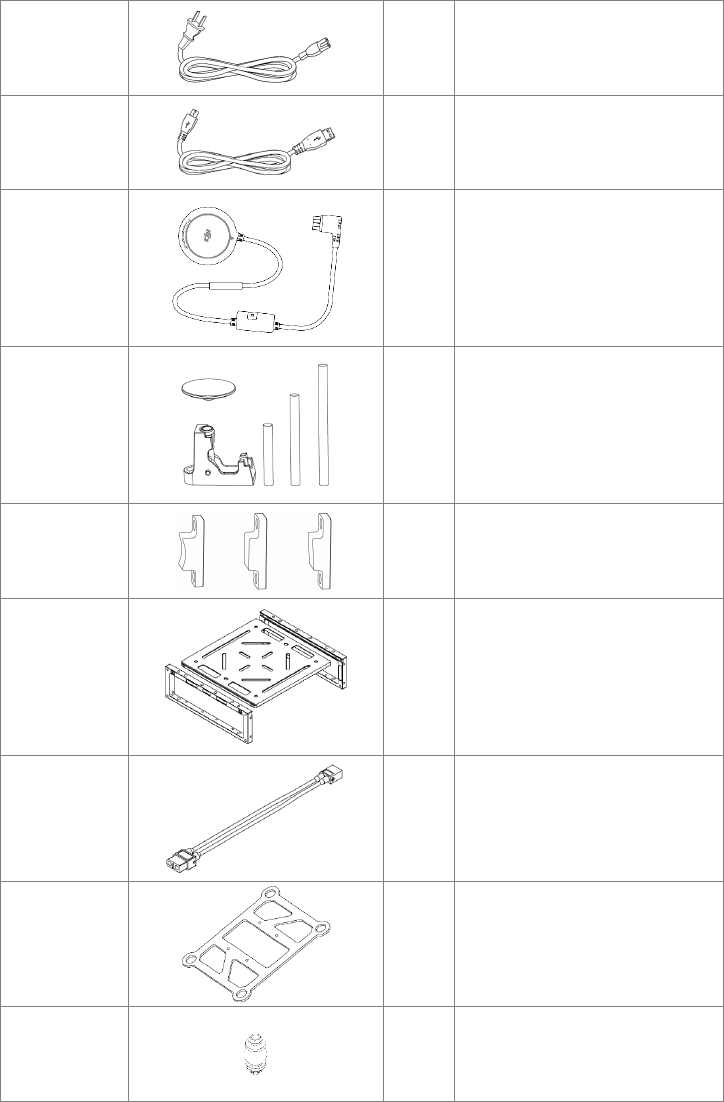
©2015 DJI. All Rights Reserved. 8
Power Cable 1 To connect the charger to AC
Micro-USB
Cable
1 To connect to the Assistant software
GPS Module 1 Model: GPS-COMPASS PRO PLUS
GPS Bracket
(Set)
1
GPS Collapsible Mount x1, Strut x3 (80
mm, 120 mm, 160 mm)
Arm Blocks 12
Arm Block 1 x4, Arm Block 2 x4, Arm
Block 3 x4
Expansion Bay
(Set)
2 Side Plate x4, Lower Plate x2
XT30-XT60
Cable
1
Mounting Plate
for Gimbal
1
Damper 8
To connect the mounting plate for
gimbal and the upper plate of the
center frame
©2015 DJI. All Rights Reserved. 9
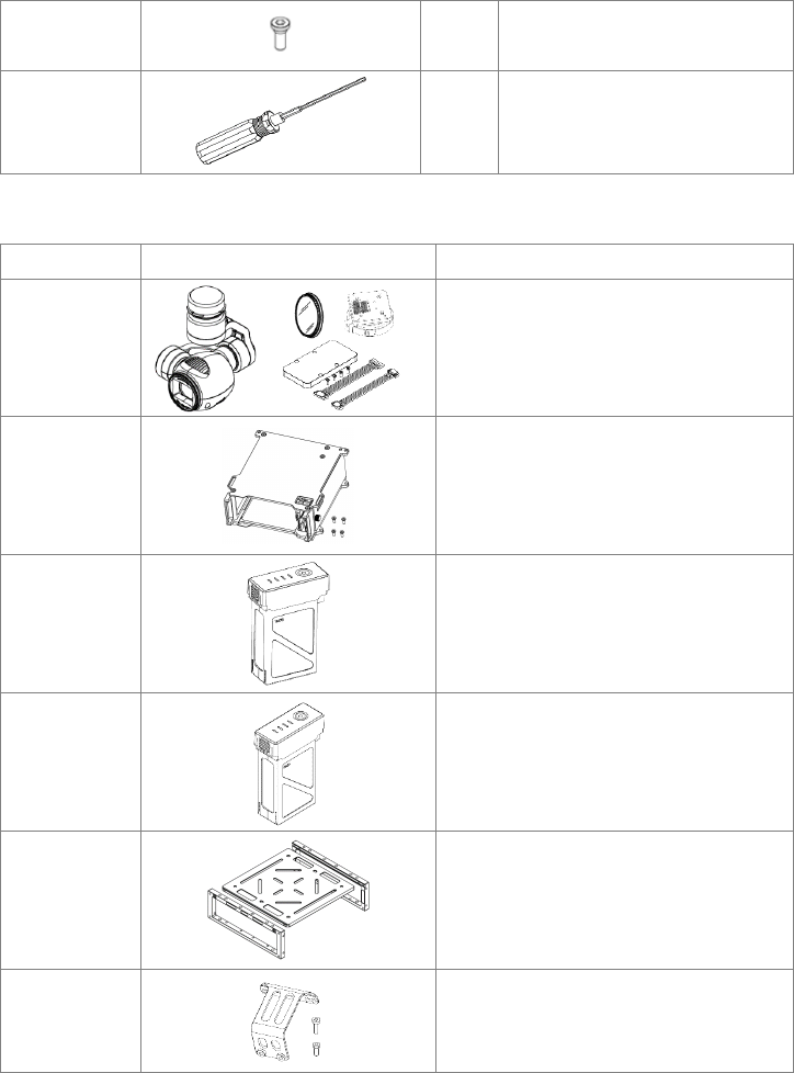
Screws (Pack) 2
M2.5x5, M2.5x8, M3x5, M2x5, M3x8
(self-tapping)
2.0 Hex Key
To adjust screws
Optional Items
Name Diagram Description
ZENMUSE X3
Gimbal with
Camera Kit
Gimbal with Camera x1, ND Filter x1, Gimbal
Lock x1, Gimbal Cable Cover x1, 8-pin Gimbal
Cable x1, Phillips Screws x4
Battery
Compartment
To use another TB47D/TB48D Intelligent Flight
Battery
TB47D
Intelligent Flight
Battery
TB48D
Intelligent Flight
Battery
Expansion Bay Side Plate x2, Lower Plate x1, Screw (M2.5x5) x4
Guidance
System
Connector Kit
Connector (with dampers) x10, Screws (M2x5)
x30, Screws (M2x4.2) x30

©2015 DJI. All Rights Reserved. 10
Tools Required
Tools Use
Phillips Screwdriver Mounting screws.
Thread Locker Securing screws.
Nylon Cable Tie
Binding devices and wires.
Scissors
Cutting Pliers/Dykes
©2015 DJI. All Rights Reserved. 11
Checking Frame Arms (with the Landing Gear)
1. Ensure all motors are mounted correctly and firmly, and that they rotate freely.
2. Ensure the landing gear is mounted firmly and antenna covers are in good condition.
3. Ensure all cables are intact.
4. Identify the M1 ~ M4 marks on the frame arms. Mount each frame arm to its corresponding position on the center
frame.
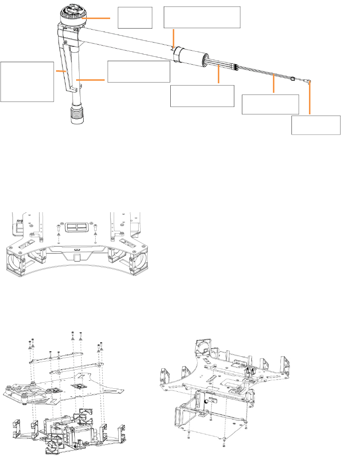
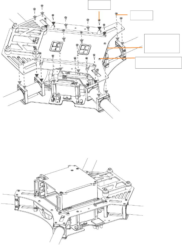
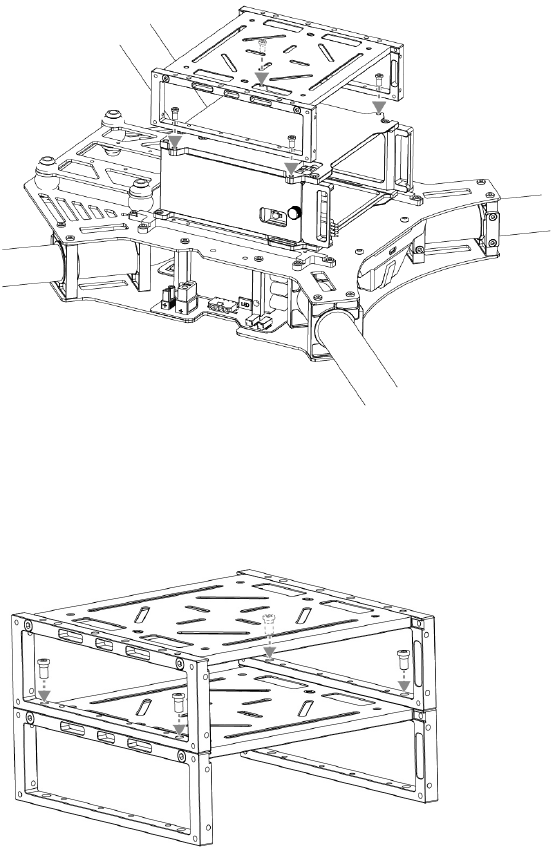
Checking the Center Frame
1. Remove the two screws (M3x8 self-tapping) for the aircraft status indicator and then remove the indicator gently
to avoid cable damage.
2. Remove the eight screws (M2.5x8) on the expansion bars on the upper plate of the center frame, and then
remove the expansion bars and the upper plate.
3. Remove the four screws (M2.5x5) on the battery compartment and then remove it.
Motor
Landing Gear
Antenna
Cover Motor Cables
LED Cable
Antenna
M1~M4 Mark
©2015 DJI. All Rights Reserved. 12
4. Check the center frame. Ensure that parts such as the flight controller, the ESCs, etc. are in good condition, and
that the ports two ends of each cable connected to have the marks of the same color.
Flight Controller
ESC
Aircraft Status Indicator
(on the upper plate of the frame arm)
©2015 DJI. All Rights Reserved. 13
Mounting Frame Arms
1. Identify the M1 ~ M4 marks on the arms and the mounting positions of the center frame. Mount each frame arm to
its corresponding position on the center frame.
2. Insert each frame arm into mounting position A and B on the center frame successively until the arm ring reaches
mounting position A.
3. Arm Blocks are needed to secure the arm when mounting. There are three kinds of blocks that come with the M100.
Arm Block 1: A circular side surface, mounted into the slot at mounting position B
Arm Block 2: A vertical side plane, when mounted into the slot at mounting position A, the propeller rotating
plane is perfectly horizontal.
Arm Block 3: A 3° inclined side plane, when mounted into the slot at mounting position A, the propeller rotating
plane is at a 3° inclination.
Block 1 Block 2 Block 3
Mount block 1 into the slot at mounting position B. Choose block 2 or 3 according to your needs, and then mount
it into the slot at mounting position A. Ensure that the arm ring fits perfectly into the side of the block. Insert four
M2.5x5 screws and tighten.
Mounting Position B
Mounting Position A
Arm Ring
©2015 DJI. All Rights Reserved. 14
Arm Block 2
Arm Block 3
4. Plug the three motor cables for each motor into the ports on the corresponding ESC. Note that each cable
corresponds to the port with a mark of the same color.
5. Plug each LED cable into the port on the corresponding ESC.
6. Plug each antenna into the corresponding port on back of the flight controller. Note the sequential antenna ports
shown below.
LED Cable
Motor Cables
Color Marks
M1~M4 Mark
LED Port
Antenna Ports on back of the flight controller
©2015 DJI. All Rights Reserved. 15
7. Ensure the motor cables, LED cable, and antenna cable of each arm are correctly installed into their
corresponding ports.
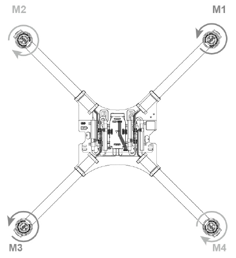
8. Double check all frame arms. Arms M1 and M2 are the forward facing (nose), arms M3 and M4 are the tail. Seen
from the top, motors on arms M1, M3 rotate counter clockwise while those on arms M2, M4 rotate clockwise.
©2015 DJI. All Rights Reserved. 16
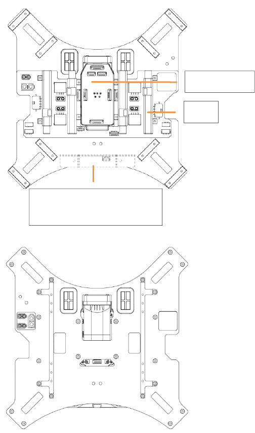
Mounting the Battery Compartment and Wiring
Recommended Mounting Position (under the center frame)
The center of gravity for the aircraft has been pre-adjusted. If you need to adjust the fore-and-aft direction’s
gravity, mount the battery compartment on the center frame (optional mounting position).
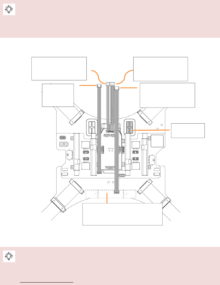
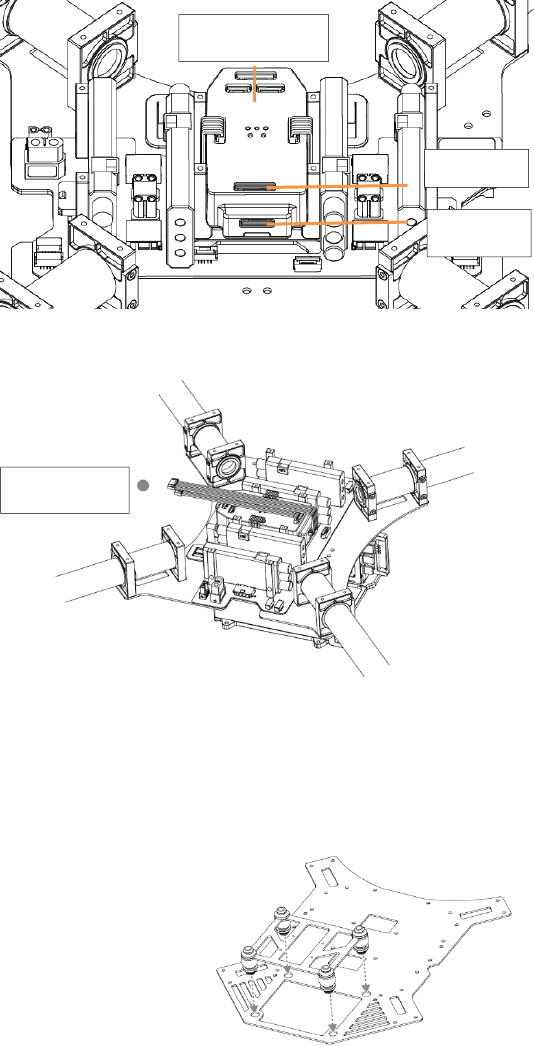
1. Pull the aircraft status indicator cable, the CAN cable, the signal cable, and power cable of the flight controller
through the wire outlet on the right side of the lower plate of the center frame.
2. Replace the upper plate of the center frame and tighten the 16 screws (M2.5x5). Then replace the expansion bars
and tighten the 8 screws (M2.5x8).
If using DJI ZENMUSE X3 Gimbal with Camera, replace the upper plate after mounting the gimbal and wiring.
Refer to Mounting the Gimbal (P30) for more information on mounting and wiring.
3. Replace the aircraft status indicator and tighten the two screws (M3x8 self-tapping). Do not over tighten the
screws to avoid damage to the screw holes.
CAN Cable
(5-pin)
Aircraft Status Indicator
Cable (6-pin)
Flight Controller Power
Cable (4-pin)
Flight Controller Signal
Cable (6-pin)
Aircraft Status Indicator
(on the upper plate of the frame arm)
Wire Outlet
©2015 DJI. All Rights Reserved. 17
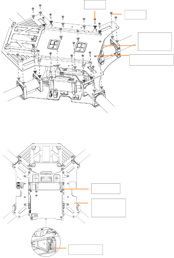
4. With the side that has metal terminals placed near the aircraft tail, tighten four screws (M2.5x5) to mount the
battery compartment onto the expansion bars on the lower plate of the center frame.
The lower plate of
the center frame
Metal Terminals
M2.5x5
M2.5x8
M2.5x5
M3x8 (self-tapping)
Aircraft Status
Indication
©2015 DJI. All Rights Reserved. 18
Optional Mounting Position (on the center frame)
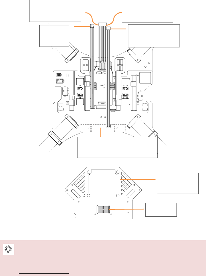
1. Pull the aircraft status indicator cable, CAN cable, signal cable and power cable from the flight controller through
the wire outlet on the upper plate.
2. Replace the upper plate of the center frame and tighten the 16 screws (M2.5x5). Then replace the expansion bars
and tighten the 8 screws (M2.5x8).
If using DJI ZENMUSE X3 Gimbal and Camera, replace the upper plate after mounting the gimbal and wiring.
Refer to Mounting the Gimbal (P30) for more information on mounting and wiring.
3. Replace the aircraft status indicator and tighten the two screws (M3x8 self-tapping). Do not over tighten the
screws to avoid damage to the screw holes.
CAN Cable
(5-pin)
Aircraft Status Indicator
Cable (6-pin)
Flight Controller Power
Cable (4-pin)
Flight Controller Signal
Cable (6-pin)
Aircraft Status Indicator
(on the upper plate of the center frame)
Wire Outlet
Upper Plate of the
Center Frame
©2015 DJI. All Rights Reserved. 19
4. With the side that has battery terminals placed near the tail, tighten four screws (M2.5x5) to mount the battery
compartment onto the expansion bars on the upper plate of the center frame.
5. To adjust gravity of the aircraft on the fore-and-aft directions, adjust the position of the battery compartment
relative to the expansion bars according to your needs.
Wiring
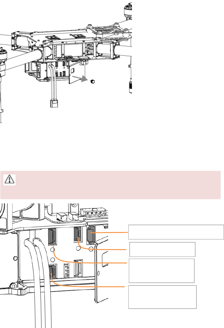
1. Remove the screw on side of the battery compartment and then open the side panel.
M2.5x8
M2.5x5
M3x8 (self-tapping)
Aircraft Status
Indication
©2015 DJI. All Rights Reserved. 20
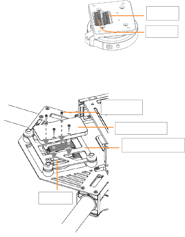
2. Plug the aircraft status indicator cable into the 6-pin port.
3. Plug the power cable of the flight controller into the 4-pin port. Plug the signal cable of the flight controller into
the 6-pin port.
4. Plug the CAN cable into the CAN1 port of the battery compartment.
Pull the cables through the slot between the side panel and the body of the battery compartment before
plugging them in.
Aircraft Status Indicator Cable Port (6-pin)
CAN1 Port (5-pin)
Port for the Flight Controller
Power Cable (4-pin)
Port for the Flight Controller
Signal Cable (6-pin)
©2015 DJI. All Rights Reserved. 21
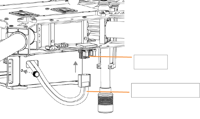
5. Pull the battery’s power cable through the hole on the side panel and then plug the cable into the XT60 port on
the center frame.
6. Close the side panel of the battery compartment. Then re-tighten the screw.
XT60 Port
Power Cable of the Battery
©2015 DJI. All Rights Reserved. 22
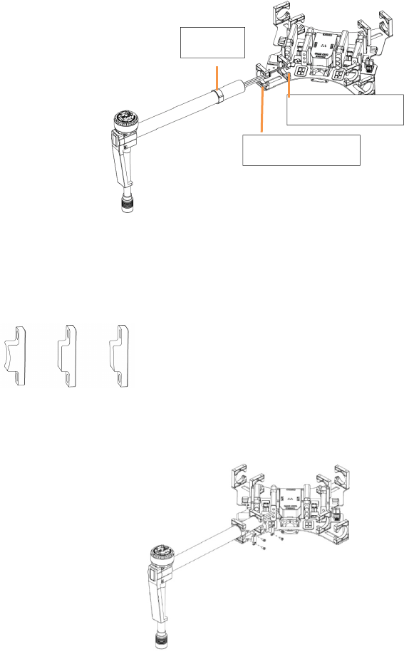
Mounting Expansion Bays
Users can extend the center frame of the M100 to mount other DJI modules and products if needed, such as
Guidance, etc. The expansion bays could be mounted on or under the center frame or the battery compartment.
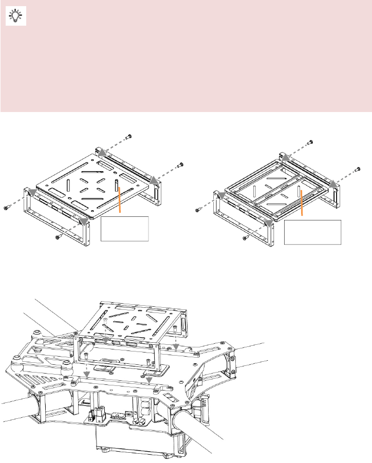
One side of the lower plate of the expansion bay is smooth, and the other side is not smooth. Choose the
orientation of the lower plate according to your needs when mounting.
There are two sets of expansion bays that come with the M100. One of them has mounting marks and a
direction arrow to help you properly mount Guidance. If using Guidance, mount the system according to the
marks.
1. Slide the lower plate of the expansion bay into the slots of the two side plates. Tighten four M2.5x5 screws.
2. Mount the expansion bay onto the mounting position of the expansion bars and tighten the four M2.5x5 screws.
Or, mount the expansion bay onto the battery compartment and tighten the four M3x5 screws.
e.g. 1 Mounting on the expansion bars
Smooth Not Smooth
©2015 DJI. All Rights Reserved. 23
e.g. 2 Mounting on the battery compartment
3. If mounting two sets of expansion bays close to each other, connect them with four M3x5 screws as shown below.
©2015 DJI. All Rights Reserved. 24
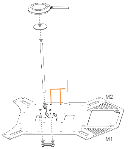
Mounting the GPS Module
1. Attach the collapsible GPS mount to one side of the center frame using M2.5×8 screws.
2. Mount a GPS module to the GPS mount with a strut. Ensure the arrow points toward the nose (M1, M2) and avoid
catching your fingers in the bracket when folding for transportation.
GPS Mount on the other side
©2015 DJI. All Rights Reserved. 25
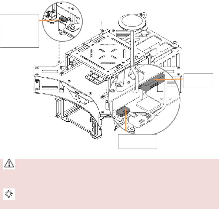
3. Attach the CAN HUB of the GPS module onto the plate of the center frame.
4. Plug the CAN cable into the CAN port for GPS module on the lower plate of the center frame.
(1) Mount the GPS with a bracket to avoid interference from the center frame power board.
(2) Use glue to install the GPS strut. Ensure it is firm and stable before every flight.
Use a strut of different length (80 mm, 120 mm, 160 mm) to mount the GPS module according to your needs.
CAN HUB
GPS CAN Port
GPS CAN Port
on the other
side
©2015 DJI. All Rights Reserved. 26
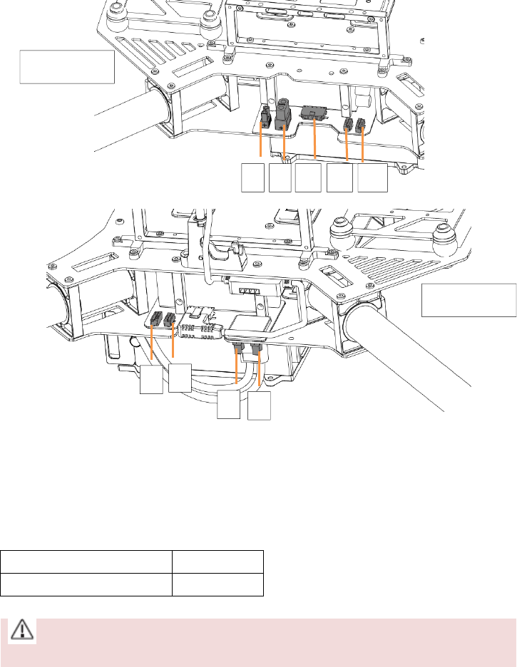
Reserved Ports Description
There are five kinds of ports reserved on the center frame. Connect your own devices to them.
[1] XT30 Port [2] XT60 Port [3] GPS CAN Port [4] CAN1 Port [5] UART Port
XT30 Ports and XT60 Ports
There are three XT30 ports and one XT60 port reserved on the center frame. Supply power for your own devices
by connecting them to these reserved ports. Use the XT30-XT60 cable if needed. Identify the positive and negative
terminals of each port when connecting.
The specifications of these four reserved ports are as shown below:
Output Voltage Range 20 ~ 26.1 V
Max. Persistent Output Current 10 A
The total current of the one XT60 port and the three XT30 ports should not exceed 10 A.
5 431 2
11
4
5
Aircraft Nose
Aircraft Nose
©2015 DJI. All Rights Reserved. 27
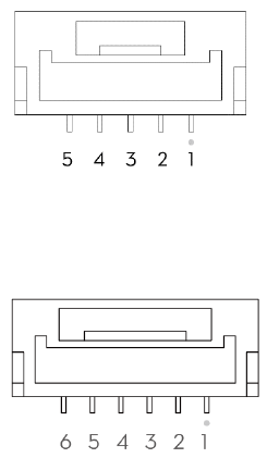
CAN Ports and UART Ports
There is one GPS CAN port, two CAN1 ports (5-pin), and two UART ports (6-pin) reserved on the center frame. You
can connect other devices to these ports, as required.
The pin definitions of the CAN1 port and the UART port are as shown below:
CAN1 Port (with a white dot beside pin 1):
[1] GND [2] CANL [3] CANH [4] GND [5] VCC 7.4V
UART Port (with a white dot beside pin 1):
[1] UART TXD [2] UART RXD [3] GND [4] CANL [5] CANH [6] VCC 6 V
©2015 DJI. All Rights Reserved. 28
Attaching Propellers
Propeller Safety
1. Always be sure to install the propellers onto the correct motors, as indicated in this guide. Rotation indicators are
found on both the motors and propellers, ensuring that the correct orientation can be clearly determined. Be
careful when installing and removing the propellers.
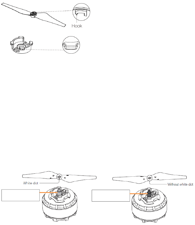
2. The propeller set may show wear after continuous use. Inspect the hooks inside the propeller nut and mounting
plate for wear, as shown below. If you have trouble identifying signs of wear, refer to Step 3 of the Installation
section for more information. Be sure to replace the propeller and the mounting plate if they have become worn.
Mounting Plate
3. Ensure that the mounting plate and securing spring are firmly attached to the motor before every flight.
4. Propellers should never be used after they have been involved in a crash or collision. If such an event occurs,
replace the propellers before flying again.
5. The propellers, securing springs, and mounting plates have an approximate lifespan of 200 flights. Inspect them
regularly to determine if they should be replaced sooner.
6. Always follow the prescribed storage procedures to avoid damaging the propellers.
Installation
1. Install the propellers with a white dot onto the motors with a gray screw, and install the propellers without a white
dot onto the motors with a black screw.
Gray Screw Black Screw
©2015 DJI. All Rights Reserved. 29
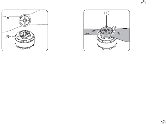
2. Align the hook (A) on the propellers with the securing spring (B), then press down the propeller onto the
mounting plate then rotate the propellers according to the lock direction until it is secured.
3. Installation is complete. Remember to always match the axis colors and direction indicators, thus ensuring that the
propellers are properly attached and secured.
To ensure that the propellers have been properly secured, hold the motor in place with one hand and use your
other hand to try to rotate the propeller in the unlock direction without pressing down. If the propeller can be
removed this way, the propeller and/or the mounting plate have become worn and should be replaced before
flying the M100 again.
Press the propellers downward firmly then rotate the propeller in the unlock direction to unlock the propellers.
©2015 DJI. All Rights Reserved. 30
Mounting the Gimbal (Optional)
The M100 is compatible with DJI ZENMUSE X3 gimbal and camera. Do NOT use other gimbals.
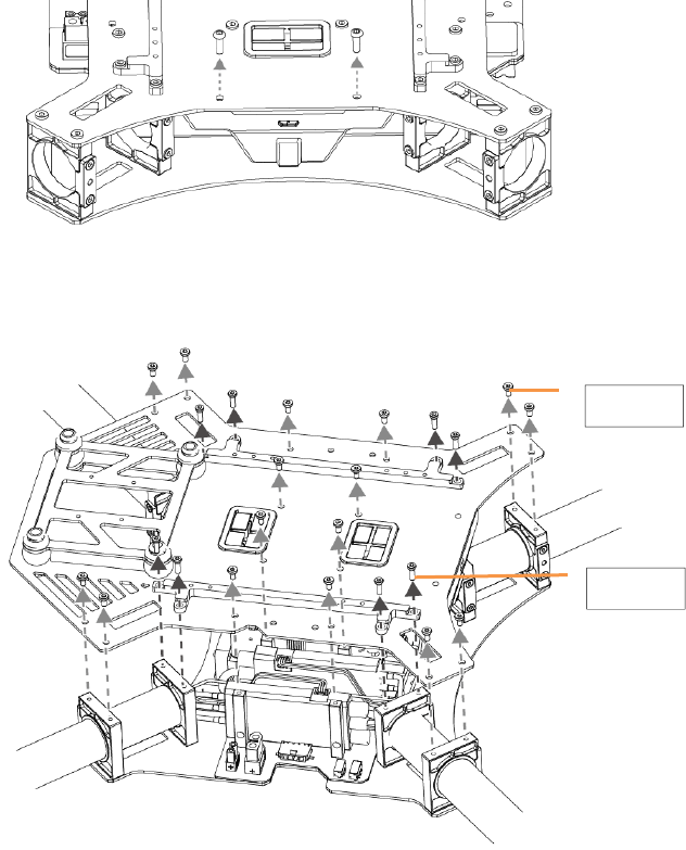
Mounting the Gimbal Lock and Wiring
1. Remove the two screws (M3x8 self-tapping) for the aircraft status indicator and then remove the indicator gently
to avoid cable damage.
2. Remove the 16 screws (M2.5x5) on the upper plate of the center frame and the eight screws (M2.5x8) on the
expansion bars. Then remove the expansion bars and the upper plate.
M2.5x8
M2.5x5
©2015 DJI. All Rights Reserved. 31
3. Plug one end of the 10-pin gimbal cable into the 10-pin port on the flight controller. Plug one end of the 8-pin
gimbal cable into the 8-pin port on the flight controller.
4. Place the other end of the gimbal cables towards the nose of the aircraft.
5. Replace the upper plate of the center frame and tighten the 16 screws (M2.5x5). Then replace the expansion bars
and tighten the 8 screws (M2.5x8).
6. Replace the aircraft status indicator and tighten the two screws (M3x8 self-tapping). Do not over tighten to avoid
damage to the screw holes.
7. Mount the gimbal mounting plate to the center frame using the four dampers.
10-
p
in Port
8-pin Port
Flight Controller
Aircraft Nose
©2015 DJI. All Rights Reserved. 32
8. Plug the other end of the 10-pin gimbal cable into the 10-pin port on the gimbal lock. Plug the other end of the
8-pin gimbal cable into the 8-pin port on the gimbal lock.
Gimbal Lock
9. Mount the gimbal lock to the mounting plate using the gimbal cable cover and four Phillips screws. Tighten the
four screws (M2) to mount the Gimbal Lock to the mounting plate.
8-pin Port
10-
p
in Port
Gimbal Cable Cover
Phillips Screws
Gimbal Lock
Mounting Plate for Gimbal
©2015 DJI. All Rights Reserved. 33
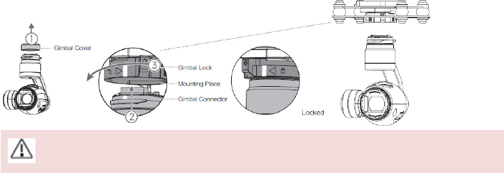
The quick-release mount of the DJI ZENMUSE X3 gimbal with camera allows you to mount and remove the camera
with ease. Follow the instructions below:
Mounting the Gimbal and Camera:
1. Remove Gimbal Cover.
2. Rotate the Gimbal Lock to the unlocked position (to the right when facing the nose of the aircraft). Insert the
gimbal by aligning the white mark on the Gimbal.
3. Rotate the Gimbal Lock back into the locked position. Ensure that the gimbal is securely locked.
Ensure the Micro-SD card is correctly inserted into the camera.
Removing the Gimbal and Camera:
Hold the upper part of the gimbal still. Rotate the Gimbal Lock to the unlocked position and then remove the
gimbal.
©2015 DJI. All Rights Reserved. 34
Using the DJI Intelligent Flight Battery
Introduction
The DJI Intelligent Flight Battery has a capacity of 4500mAh, voltage of 22.2V, and smart charge-discharge
functionality. It can only be charged with an appropriate DJI approved charger.
Intelligent Flight Battery Charger
Battery must be fully charged before using it for the first time. Refer to "Charging the Intelligent Flight
Battery" for more information.
DJI Intelligent Flight Battery Functions
1. Battery Level Display: LEDs display the current battery level.
2. Battery Life Display: LEDs display the current battery power cycle.
3. Auto-discharging Function: The battery automatically discharges to below 65% of total power when it is idle
(press the power button to check battery level will cause battery to exit idle state) for more than 10 days to
prevent swelling. It takes around 2 days to discharge the battery to 65%.It is normal to feel moderate heat
emitting from the battery during the discharge process. Discharge thresholds can be set in the DJI Pilot app.
4. Balanced Charging: Automatically balances the voltage of each battery cell when charging.
5. Over charge Protection: Charging automatically stops when the battery is fully charged.
6. Temperature Detection: The battery will only charge when the temperature is between 0°C (32°F) and 40°C
(104°F).
7. Over Current Protection: Battery stops charging when high amperage (more than 10A) is detected.
8. Over Discharge Protection: Discharging automatically stops when the battery voltage reaches 18V to prevent
over-discharge damage
9. Short Circuit Protection: Automatically cuts the power supply when a short circuit is detected.
10. Battery Cell Damages Protection: DJI Pilot app shows warning message when damaged battery cell is detected.
11. Battery Information History: Show the last 32 entries of battery information records that include warning
messages and so on.
12. Sleep Mode: Sleep mode is entered after 10 minutes of inactivity to save power.
13. Communication: Battery voltage, capacity, current, and other relevant information is provided to the aircraft’s to
the main controller.
Refer to Disclaimer and Intelligent Flight Battery Safety Guidelines before use. Users take full
responsibility for all operations and usage.
©2015 DJI. All Rights Reserved. 35
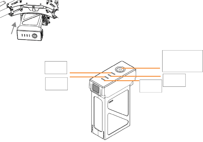
Using the Battery
Installing the Battery
Insert the Intelligent Flight Battery into the battery compartment as shown below.
Powering ON/OFF
Powering On: Press the Power Button once, then press again and hold for 2 seconds to power on. The Power LED
will turn red and the Battery Level Indicators will display the current battery level.
Powering Off: Press the Power Button once, then press again and hold for 2 seconds to power off.
Low Temperature Notice:
1. The performance of the intelligent Flight Battery is significantly reduced when flying in a low temperature
environments (those with air temperatures below 5℃). Ensure that the battery is fully charged and the cell
voltage is at 4.43 V before each flight.
2. Using the Intelligent Flight Battery in extremely low temperature environments (those with air temperatures
below -10℃) is not recommended. When flying in environments with temperatures between 5℃ and -10℃, the
Intelligent Flight Battery should be able to achieve the appropriate voltage levels (above 4.2 V), but it is
recommended that you apply the included insulation sticker to the battery in order to prevent a rapid drop in
temperatures.
3. If the DJI Pilot app displays the “Critical Low Battery Level Warning” when flying in low temperature
environments, stop flying and land the aircraft immediately. You will still be able to control the aircraft’s
movement when this warning is triggered.
4. Store the Intelligent Flight Battery in a room temperature environment and ensure that its temperature exceeds
5℃ before using it in the low temperature environment.
5. When using the M100 in a low temperature environment, begin by allowing the aircraft to hover at a low altitude,
for approximately one minute, to heat the battery.
6. To ensure optimum performance, keep the Intelligent Flight Battery’s core temperature above 20℃ when in
use.
LED1
Power Button
(
Built-in LED
)
LED3
LED2
LED4
©2015 DJI. All Rights Reserved. 36
Checking the Battery Level
The Battery Level Indicators display how much remaining power the battery has. When the battery is powered off,
press the Power Button once. The Battery Level Indicators will light up to display the current battery level. See
below for details.
The Battery Level Indicators will also show the current battery level during charging and discharging.
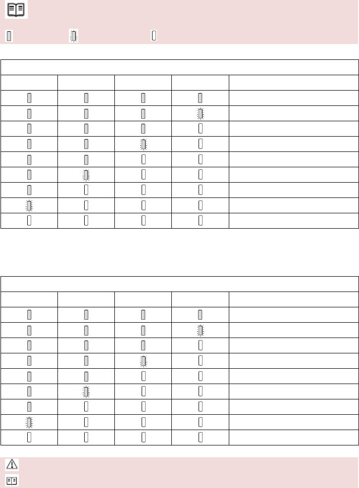
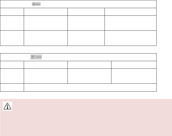
The indicators are defined below.
: LED is on. : LED is flashing. : LED is off.
Battery Level
LED1 LED2 LED3 LED4 Battery Level
87.5%~100%
75%~87.5%
62.5%~75%
50%~62.5%
37.5%~50%
25%~37.5%
12.5%~25%
0%~12.5%
=0%
Checking the Battery Life
The battery life indicates how many more times the battery can be discharged and recharged before it must be
replaced. When the battery is powered off, press and hold the Power Button for 5 seconds to check the battery life.
The Battery Level Indicators will light up and/or blink as described below for 2 seconds:
Battery Life
LED1 LED2 LED3 LED4 Battery Life
90%~100%
80%~90%
70%~80%
60%~70%
50%~60%
40%~50%
30%~40%
20%~30%
below 20%
When battery life reaches 0%, it can no longer be used
For more information about the battery, launch DJI Pilot app and check the information under the battery tab.
©2015 DJI. All Rights Reserved. 37
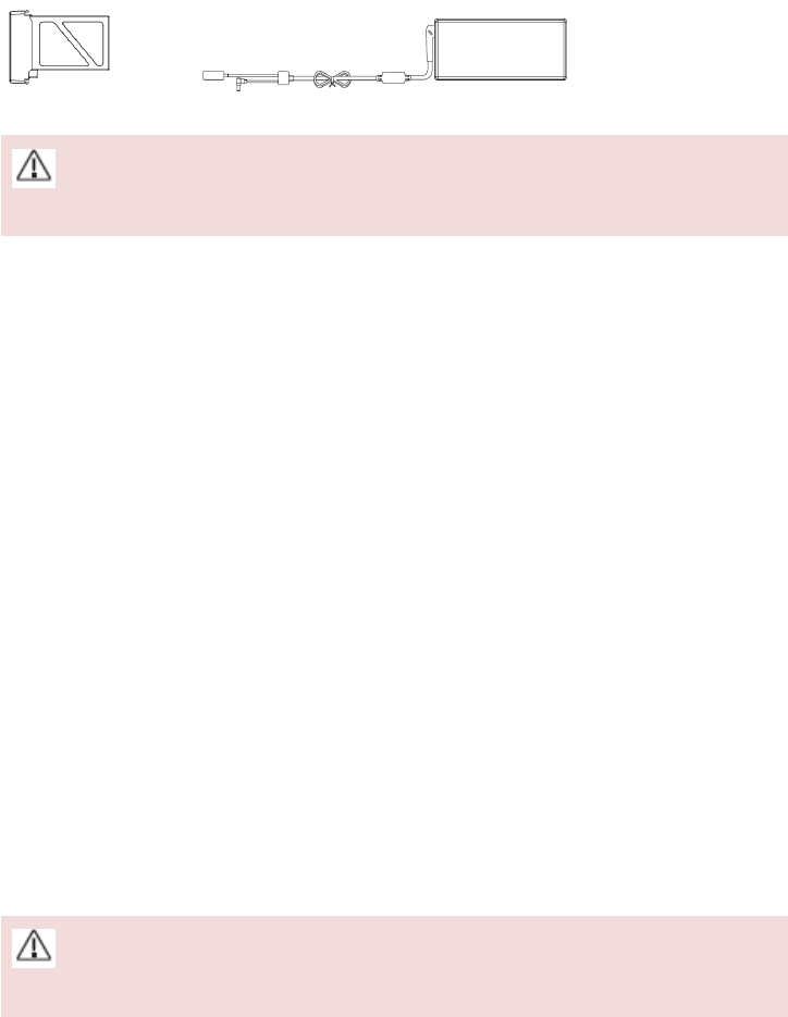
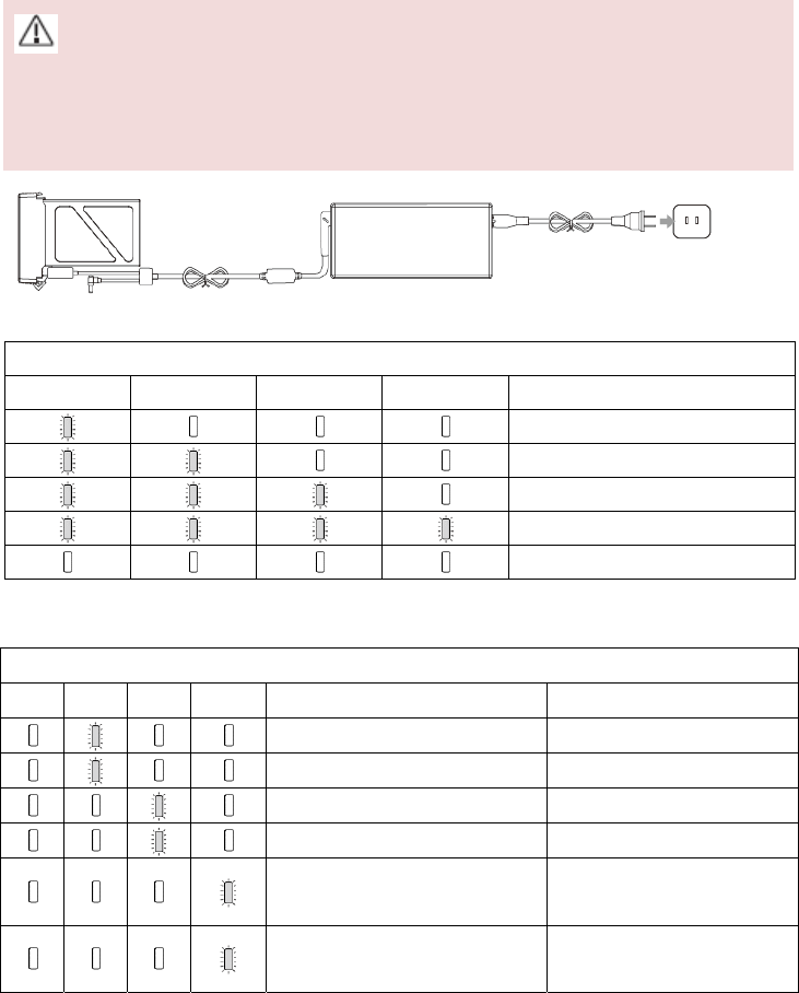
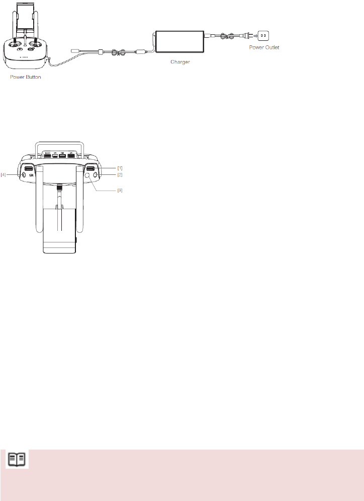
Charging the Intelligent Flight Battery
1. Connect Battery Charger to a power source (100-240V 50/60Hz).
2. Open the Protection Cap and connect the Intelligent Flight Battery to the Battery Charger. If the battery level is
above 95%, turn on the battery before charging.
3. The Battery Level Indicator will display the current battery level during charging.
4. The Intelligent Flight Battery is fully charged when Battery Level Indicators are all off.
5. Air cool the Intelligent Flight Battery after each flight. Allow its temperature to drop to room temperature before
storing it for an extended period.
Do not charge the Intelligent Flight Battery and remote controller with standard charger (model:
A14-100P1A) at the same time, otherwise the charger may overheat.
Always turn off the battery before inserting it or removing it from the M100. Never insert or remove a battery
when it is powered on.
Intelligent Flight Battery Charger Power Outlet
Battery Level Indicators while Charging
LED1 LED2 LED3 LED4 Battery Level
0%~25%
25%~50%
50%~75%
75%~100%
Fully Charged
Charging Protection LED Display
The table below shows battery protection mechanisms and corresponding LED patterns.
Battery Indicators while Charging
LED1 LED2 LED3 LED4 Blinking Pattern Battery Protection Item
LED2 blinks twice per second Over current detected
LED2 blinks three times per second Short circuit detected
LED3 blinks twice per second Over charge detected
LED3 blinks three times per second Over-voltage charger detected
LED4 blinks twice per second
Charging temperature is too low
(<0°C)
LED4 blinks three times per second
Charging temperature is too
high (>40°C)

©2015 DJI. All Rights Reserved. 38
After any of the above mentioned protection issues are resolved, press the button to turn off the Battery Level
Indicator. Unplug the Intelligent Flight Battery from the charger and plug it back in to resume charging. Note that
you do not need to unplug and plug the charger in the event of a room temperature error, the charger will resume
charging when the temperature falls within the normal range.
DJI does not take any responsibility for damage caused by third-party chargers.
How to discharge your Intelligent Flight Battery:
To effectively calibrate the battery capacity, it is recommended to charge and discharge the battery thoroughly
for every 10 charge-and-discharge cycle. User should install the battery onto the aircraft and then power on the
aircraft to initiate the discharge process, discharge the battery until the aircraft is powered off automatically.
User should then fully charge the battery to ensure the battery is working at its optimal.
Slow: Place the Intelligent Flight Battery into the M100’s Battery Compartment and power it on. Leave it on
until there is less than 5% of power left, or until the battery can no longer be turned on. Launch the DJI Pilot
app to check battery level.
Rapid: Fly the M100 outdoors until there is less than 5% of power left, or until the battery can no longer be
turned on.
©2015 DJI. All Rights Reserved. 39
Using the Remote Controller
Remote Controller Profile
The Remote Controller is a multi-function wireless communication device that integrates the video downlink ground
system and aircraft Remote Controller system. The video downlink and aircraft Remote Controller system operate
at 2.4 GHz with maximum transmission distance of 2km. The remote controller features a number of camera
functions, such as taking and previewing photos and video, and controlling gimbal motions. The remote controller is
powered by a 2S rechargeable battery. The current battery level is displayed by LEDs on the front panel of the
remote controller. (A DJI ZENMUSE X3 Gimbal with Camera is required when using the gimbal and camera
functions)
(1) Compliance Version: The Remote Controller is compliant with both CE and FCC regulations.
(2) Operating Mode: Control can be set to Mode 1, Mode 2.
(3) Mode 1: The right stick serves as the throttle.
(4) Mode 2: The left stick serves as the throttle.
Do not operate more than 3 aircrafts within in the same area (size equivalent to a soccer field) to prevent
transmission interference.
Preparing Remote Controller
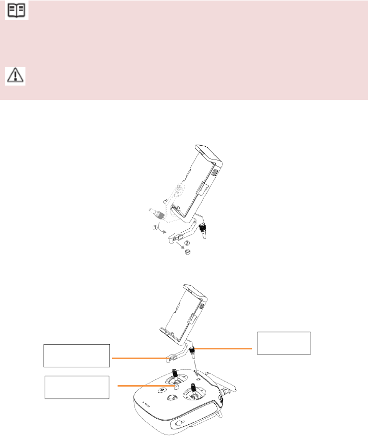
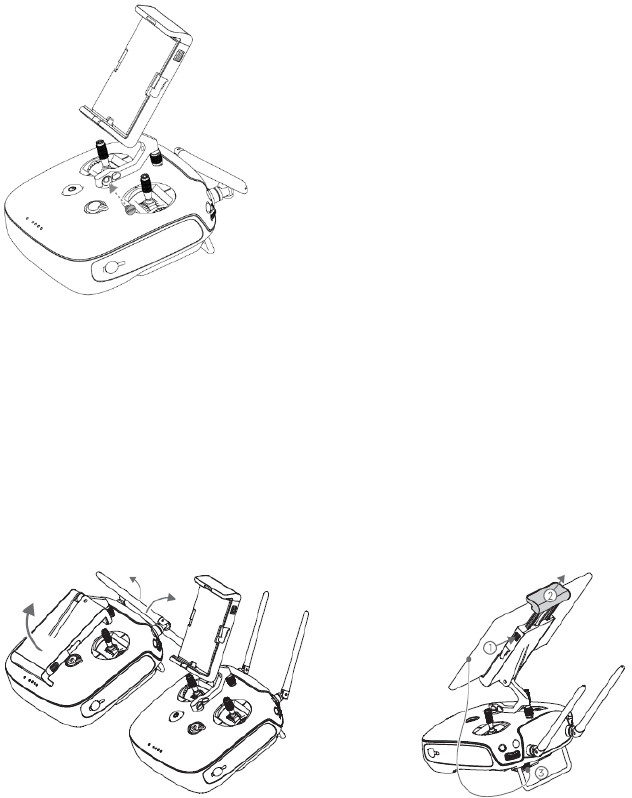
Mounting the Mobile Device Holder:
1. Unfold the Mobile Device Holder. Remove the securing screw with a screwdriver.
2. Plug the Mobile Device Holder into the mounting hole on the remote controller and tighten the top screw.
Top Screw
Mounting Hole
Metal Loop
©2015 DJI. All Rights Reserved. 40
3. Line up the hole on the Mobile Device Holder with the metal loop on the remote controller. Insert and tighten the
securing screw.
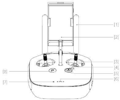
Tilt the Mobile Device Holder to the desired position then adjust the antenna as shown.
1. Press the button on the side of the Mobile Device Holder to release the clamp, adjust it to fit then attach your
mobile device.
2. Connect your mobile device to the remote controller with a USB cable.
3. Plug one end of the cable into your mobile device, and the other end into the USB port on the back of the remote
controller.
©2015 DJI. All Rights Reserved. 41
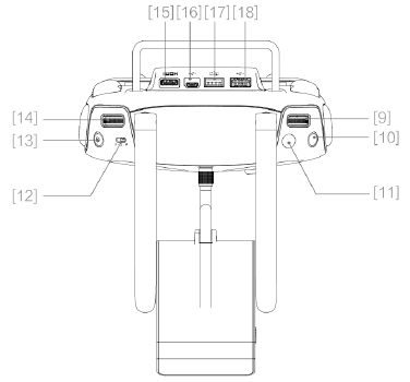
Remote Controller Diagram
[1] Antennas
Relays aircraft control and video signal.
[2] Mobile Device Holder
Mounting place for your mobile device.
[3] Control Stick
Controls aircraft orientation.
[4] Return Home (RTH) Button
Press and hold the button to initiate Return to Home (RTH).
[5] RTH LED
Circular LED around the RTH button displays RTH status.
[6] Battery Level LEDs
Displays the current battery level.
[7] Status LED
Displays the power status.
[8] Power Button
Used to power on or power off the remote controller.
©2015 DJI. All Rights Reserved. 42
[9] Camera Settings Dial
Turn the dial to adjust camera settings. Only functions when the remote controller is connected to a mobile
device running the DJI Pilot app.
[10] Playback Button
Playback the captured images or videos.
[11] Shutter Button
Press to take a photo. If in burst mode, the set number of photos will be taken with one press.
[12] Flight Mode Switch
Used to switch between P, A and F mode.
[13] Video Recording Button
Press to start recording video. Press again to stop recording.
[14] Gimbal Dial
Use this dial to control the tilt of the gimbal.
[15] Micro-USB Port
For connecting the remote controller to your computer.
[16] Mini-HDMI Port
Connect an HD compatible monitor to this port to get a live HD video preview of what the camera sees.
[17] CAN Bus Port
Reserved for future use.
[18] USB Port
Connect to mobile device to access all of the DJI Pilot app controls and features.
©2015 DJI. All Rights Reserved. 43
[19] GPS Module
Used to pinpoint the location of the remote controller.
[20] Back Left Button
Customizable button in DJI Pilot app.
[21] Power Port
Connect to a power source to charge the remote controller’s internal battery.
[22] Back Right Button
Customizable button in DJI Pilot app.
Remote Controller Operations
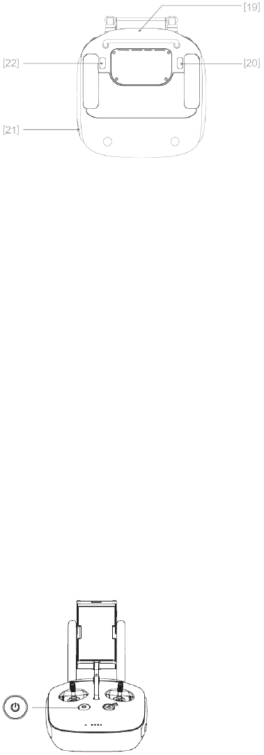
Powering On and Off the Remote Controller
The M100 remote controller is powered by a 2S rechargeable battery with a capacity of 6000mAh. The battery
level is indicated by the Battery Level LEDs on the front panel. Follow the steps below to power on your remote
controller:
1. When powered off, press the Power Button once and the Battery Level LEDs will display the current battery level.
2. Then, press and hold the Power Button to power on the remote controller.
3. The Remote Controller will beep when it powers on. The Status LED will blink green (slave remote controller
blinks solid purple) rapidly, indicating that the remote controller is linking to the aircraft. The Status LED will show a
solid green light when linking is completed.
4. Repeat step 2 to power off the remote controller after finish using it.
©2015 DJI. All Rights Reserved. 44
Charging Remote Controller
Charge the remote controller via supplied charger.
Controlling Camera
Shoot videos or images and adjust camera settings via the Shutter Button, Camera Settings Dial, Playback Button
and Video Recording Button on the remote control.
[1] Camera Settings Dial
Turn the dial to quickly adjust camera settings such as ISO and shutter speed without letting go of the remote
controller. Move the dial button to left or right to view the pictures or videos in playback mode.
[2] Playback Button
Press to view images or videos that have already been captured.
[3] Shutter Button
Press to take a photo. If burst mode is activated, multiple photos will be taken with a single press.
[4] Recoding Button
Press once to start recording video, then press again to stop recording.
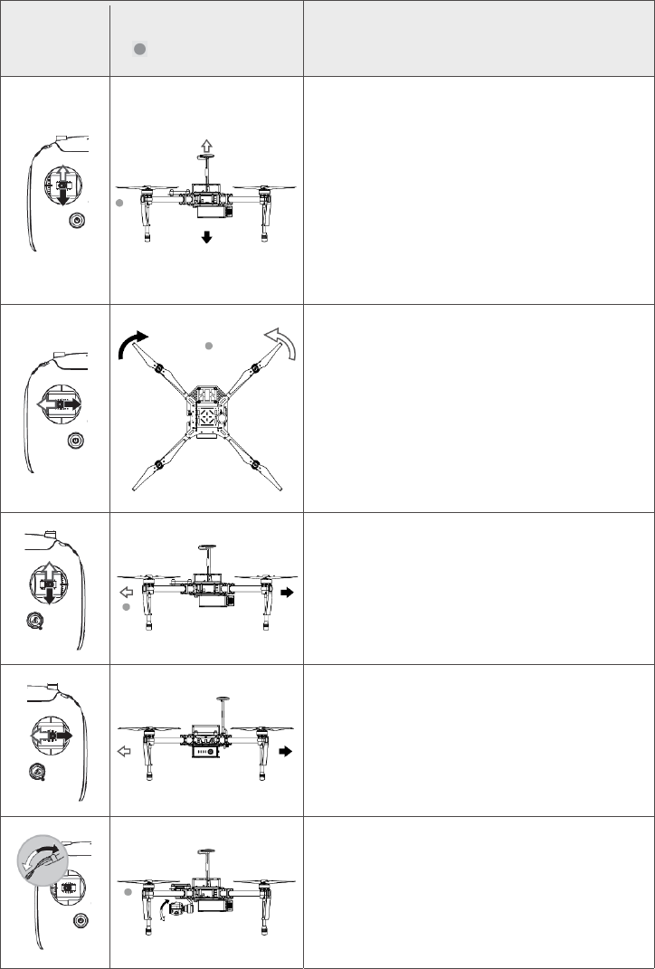
Controlling Aircraft
This section explains how to use the various features of the remote controller. The Remote Controller is set to
Mode 2 by default.
Stick Neutral/ mid point: Control sticks of the Remote Controller are placed at the central position.
Move the Stick: The control stick is pushed away from the central position.
©2015 DJI. All Rights Reserved. 45
Remote
Controller
(Mode 2)
Aircraft
( indicates nose direction) Remarks
Moving the left stick up and down changes the aircraft’s
elevation.
Push the stick up to ascend and down to descend.
Push the throttle stick up to takeoff.
When both sticks are centered, the M100 will hover in
place.
The more the stick is pushed away from the center position,
the faster the M100 will change elevation. Always push the
stick gently to prevent sudden and unexpected elevation
changes.
Moving the left stick to the left or right controls the rudder
and rotation of the aircraft.
Push the sick left to rotate the aircraft counter clock-wise,
and push the stick right to rotate the aircraft clockwise. If
the stick is centered, the M100 will stay facing its current
direction.
The more the stick is pushed away from the center position,
the faster the M100 will rotate.
Moving the right stick up and down changes the aircraft’s
forward and backward pitch.
Push the stick up to fly forward and down to fly backward.
The M100 will hover in place if the stick is centered.
Push the stick further away from the center position for a
larger pitch angle (maximum 35˚) and faster flight.
Moving the right stick control left and right changes the
aircraft’s left and right pitch.
Push left to fly left and right to fly right. The M100 will
hover in place if the stick is centered.
Push the stick further away from the center position for a
larger pitch angle (maximum 35˚) and faster flight.
Gimbal Dial: Turn the dial to the right, and the camera will
shift to point upwards. Turn the dial to the left, and the
camera will shift to point downwards. The camera will
remain in its current position when dial is static.
©2015 DJI. All Rights Reserved. 46
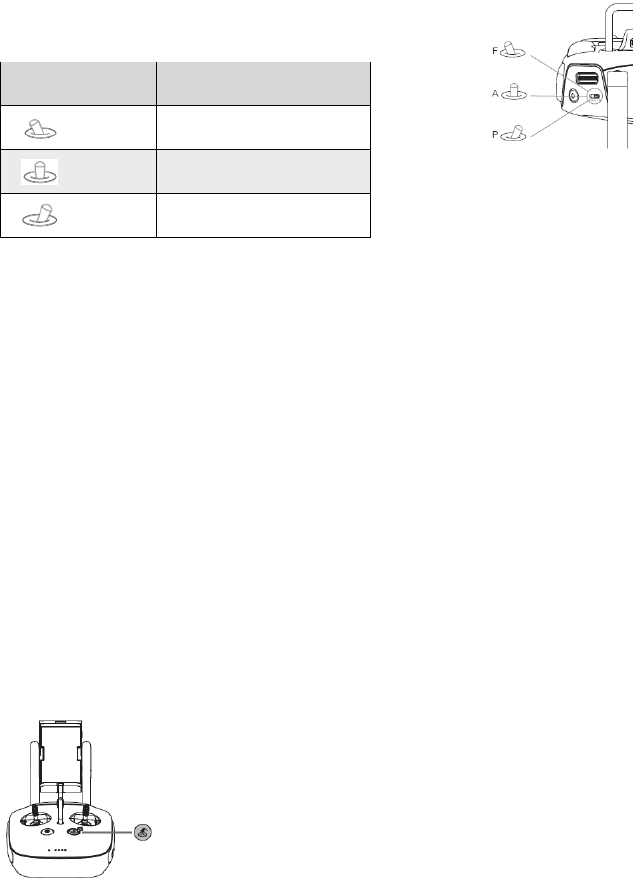
Flight Mode Switch
Toggle the switch to select the desired flight mode.
You may choose between; P mode, F mode and A mode.
Figure Flight Mode
F F mode
A A mode
P P mode
P mode (Positioning): P mode works best when GPS signal is strong. There are two different states of P mode,
which will be automatically selected by the M100 depending on GPS signal strength:
P-GPS: GPS and Vision Positioning both are available, and the aircraft is using GPS for positioning.
P-ATTI: GPS not available, aircraft is using only its barometer for positioning, so only altitude is controlled.
A mode (Attitude): The GPS is not used for holding position. The aircraft only uses its barometer to maintain altitude.
If it is still receiving a GPS signal, the aircraft can automatically return home if the Remote Controller signal is lost
and if the Home Point has been recorded successfully.
F mode (Function): The DJI SDK is required for this mode. For more information about the settings of this mode,
refer to “Basic Page” under the Using the Matrix PC Assistant (P53).
The Flight Mode Switch is locked in P mode by default. To unlock the switch, launch the DJI Pilot app, enter the
"Camera" page, tap "MODE", and then activate "Multiple Flight Mode".
RTH Button
Press and hold this button to start the Return to Home (RTH) procedure. The LED around the RTH Button will blink
white to indicate the aircraft is entering RTH mode. The aircraft will then return to the last recorded Home Point.
Press this button again to cancel the RTH procedure and regain the control of the aircraft.
Connecting Mobile Device
Tilt the Mobile Device Holder to the desired position. Press the button on the side of the Mobile Device Holder to
release the clamp, and then place your mobile device into the clamp. Adjust the clamp to secure your mobile device.
Then connect your mobile device to the remote controller with a USB cable. Plug one end of the cable into your
mobile device, and the other end into the USB port on the back of the remote controller.
©2015 DJI. All Rights Reserved. 47
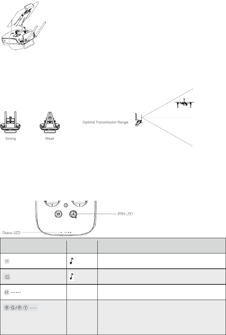
Optimal Transmission Range
The signal transmission between aircraft and remote controller perform best within the range that displayed in the
picture shown below:
Ensure the aircraft is flying within the optimal transmission range. Adjust the distance and position between the
operator and the aircraft to achieve optimal transmission performance.
Remote Controller Status LED
The Status LED reflects connection status between Remote Controller and aircraft. The RTH LED shows the Return
to Home status of the aircraft. The table below contains details on these indicators.
Status LED Alarm Remote Controller Status
— Solid Red chime The remote controller is not connected with the aircraft.
— Solid Green chime The remote controller is connected with the aircraft.
Slow Blinking Red D-D-D...... Remote controller error.
Red and Green/ Red and
Yellow Alternate Blinks
None HD Downlink is disrupted.
©2015 DJI. All Rights Reserved. 48
RTH LED Sound Aircraft Status
— Solid White chime Return to Home procedure begins.
Blinking White D . . . Sending Return to Home command to the aircraft.
Blinking White DD .. .. .. Aircraft Return to Home in progress.
The Remote Status Indicator will blink red, sound an alert, when the battery level is critically low.
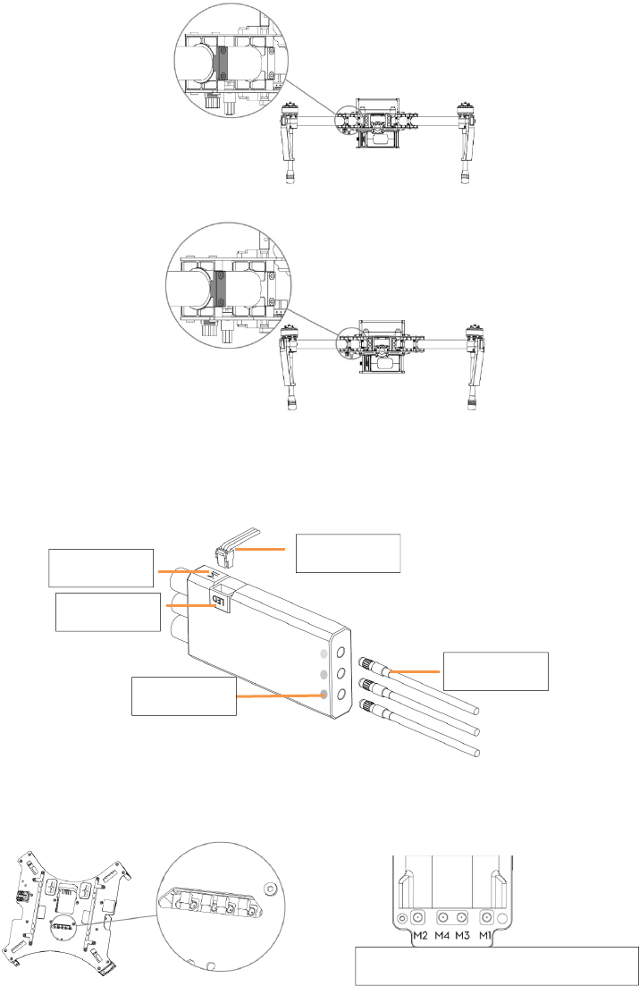
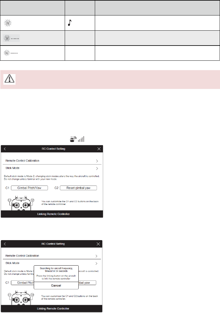
Linking the Remote Controller
The remote controller is linked to your aircraft before delivery. Linking is only required when using a new remote
controller for the first time. Follow these steps to link a new remote controller:
1. Power on the remote controller and connect to the mobile device. Launch DJI Pilot app.
2. Power on the Intelligent Flight Battery.
3. Enter “Camera” view and tap on and then tap “Linking Remote Controller” button as shown below.
4. The remote controller is ready to link. The Remote Controller Status Indicator blinks blue and "beep" sound is
emitted.
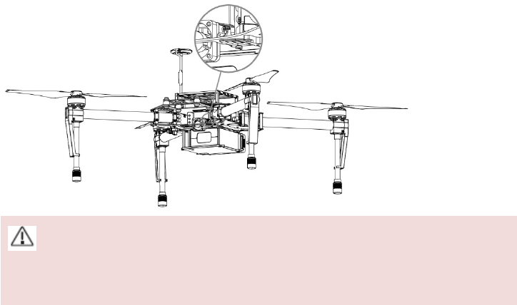
5. Locate the Linking button on the front of the aircraft, as shown in the figure shown below. Press the Linking
button to start linking. The Remote Controller Status Indicator will display solid green if Link is succeed.
©2015 DJI. All Rights Reserved. 49
Remote controller will disconnect from the linked aircraft if a new remote controller is linked to the same
aircraft.
Remote Controller Compliance Version
The remote controller is compliant with both CE and FCC requirements.
©2015 DJI. All Rights Reserved. 50
Return to Home (RTH) and Dynamic Home Point
Return to Home (RTH)
The Return to Home (RTH) brings the aircraft back to the last recorded Home Point. There are three cases that will
trigger RTH procedure; they are Smart RTH, Low Battery RTH and Failsafe RTH.
GPS Description
Home Point
The Home Point is the location at which your aircraft takes off when the GPS
signal is strong. You can view the GPS signal strength through the GPS icon
( ). If you are using the Dynamic Home Point setting, the Home Point will be
updated to your current position as you move around and when the Aircraft Status
Indicator blinks green.
Smart RTH
Using the RTH button on the remote controller (refer to “RTH button” on P46 for more information) or the RTH
button in the DJI Pilot app when GPS is available to enables smart RTH. The aircraft return to the latest recorded
Home Point, you may control the aircraft's orientation to avoid collision during the Smart RTH. Press the Smart RTH
button once to start the process, press the Smart RTH button again to exit Smart RTH and regain the control.
Low Battery RTH
The low battery level failsafe is triggered when the DJI Intelligent Flight Battery is depleted to a point that may
affect the safe return of the aircraft. Users are advised to return home or land the aircraft immediately when these
warnings are shown. DJI Pilot app will advise user to return the aircraft to the Home Point when low battery warning
is triggered. Aircraft will automatically return to the Home Point if no action is taken after 10 seconds countdown.
User can cancel the RTH by pressing once on the RTH button. The thresholds for these warnings are automatically
determined based on the current aircraft altitude and its distance from the Home Point.
Aircraft will land automatically if the current battery level can only support the aircraft to land to the ground from
the current altitude. User can use the remote controller to control the aircraft’s orientation during the landing
process.
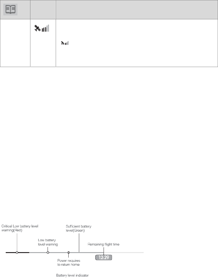
The Battery Level Indicator is displayed in the DJI Pilot app, and is described below.
©2015 DJI. All Rights Reserved. 51
Battery Level
Warning Remark Aircraft Status
Indicator DJI Pilot app Flight Instructions
Low battery
level warning
The battery
power is low.
Please land the
aircraft.
Aircraft status
indicator blinks
RED slowly.
Tap “Go-home” to have the
aircraft return to the Home
point and land automatically, or
“Cancel” to resume normal
flight. If no action is taken, the
aircraft will automatically go
home and land after 10 seconds.
Remote controller will sound an
alarm.
Fly the aircraft back and land
it as soon as possible, then
stop the motors and replace
the battery.
Critical Low
battery level
warning
The aircraft
must land
immediately.
Aircraft status
indicator blinks
RED quickly.
The DJI Pilot app screen will
flash red and aircraft starts to
descend. Remote controller will
sound an alarm.
The aircraft will begin to
descend and land
automatically.
Estimated
remaining flight
time
Estimated
remaining flight
based on
current battery
level.
N/A N/A N/A
When the critical battery level warning activates and the aircraft is descending to land automatically, you may
push the throttle upward to hover the aircraft and navigate it to a more appropriate location for landing.
Color zones and markers on the battery level indicator reflect estimated remaining flight time and are adjusted
automatically, according to the aircraft’s current status.
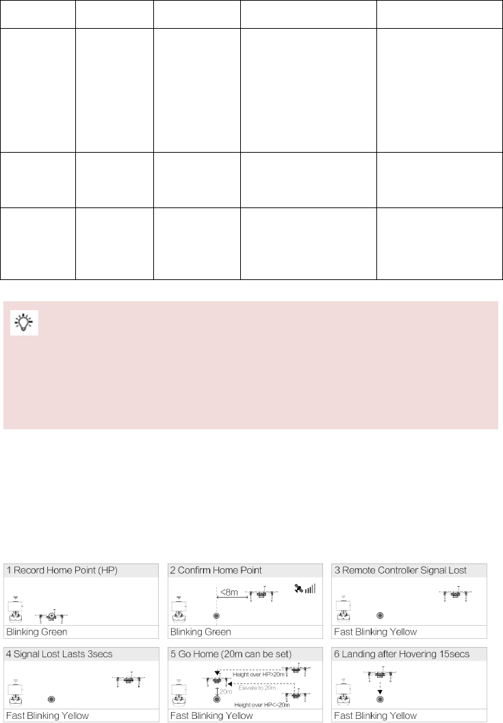
Failsafe RTH
Failsafe RTH is activated automatically if remote controller signal (including video relay signal) is lost for more than
3 seconds provided that Home Point has been successfully recorded and compass is working normally. Return home
process may be interrupted and the operator can regain control over the aircraft if a remote controller signal is
resumed.
Failsafe Illustration
©2015 DJI. All Rights Reserved. 52
Aircraft cannot avoid obstruction during the Failsafe RTH, therefore it is important to set a reasonable Failsafe
altitude before each flight. Launch the DJI Pilot app and enter “Camera” view and select “MODE” to set the
Failsafe altitude.
Aircraft will stop ascending and immediately return to the Home Point if you move the throttle stick during the
Failsafe.
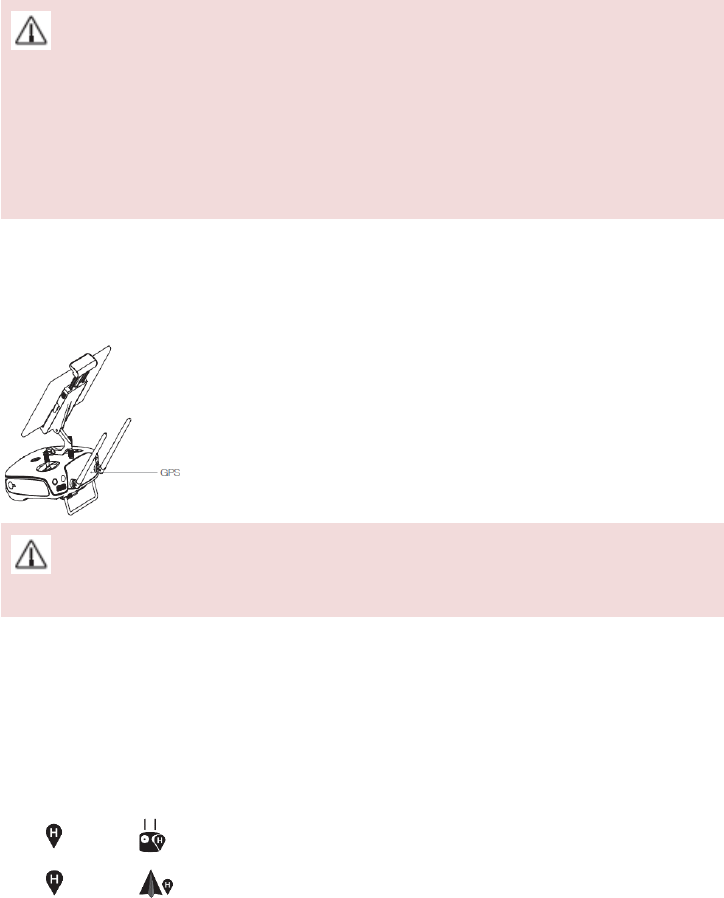
Dynamic Home Point
Dynamic home point is useful in situations when you are in motion and require a Home Point that is different from
the takeoff point. GPS module is located at the position shown in the figure below:
Ensure the space above the GPS module is not obstructed when using Dynamic Home Point.
There are two options for Dynamic Home Point.
1. Set the aircraft current coordinate as the new Home Point.
2. Set the remote controller’s coordinate as the new Home Point.
Follow the steps below to setup Dynamic Home Point:
1. Connect to the mobile device and launch the DJI Pilot app and go to the “Camera” page.
2. Tap“ ”and select“ ”, to reset the remote controller’s coordinates as the new Home Point.
3. Tap“ ”and select“ ”, to reset the aircraft’s coordinates as the new Home Point.
4. The aircraft status indicator blinks green to show Home Point is set successfully.
©2015 DJI. All Rights Reserved. 53
Using the Matrix PC Assistant
1. Download the driver installer and Assistant installer from the M100 download page.
2. Run the driver installer, and then run the Assistant installer. Follow the prompts to finish installation.
3. Turn on the Remote Controller, and then turn on the Intelligent Flight Battery in the aircraft. Connect the M100
to the computer with a Micro-USB cable. Do NOT disconnect until configuration is finished.
4. Run the Assistant. Register a DJI account and login, or login with your registered account. Wait for the M100 to
connect. Watch the indicators on the bottom of the screen. When connected, the Computer Connection status
will be solid green and Data Exchange Indicator will blink blue
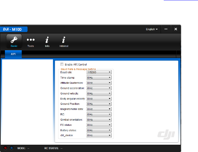
Basic Page:
If using the DJI SDK, select ‘Enable API Control’ to enable API control. The flight control system will be able to
communicate with external devices. You can control the aircraft using your own devices when the Flight Mode
Switch is toggled to F mode. Refer to the Onboard SDK Quick Start Guide (http://dev.dji.com ) for more
information about parameter settings.
©2015 DJI. All Rights Reserved. 54
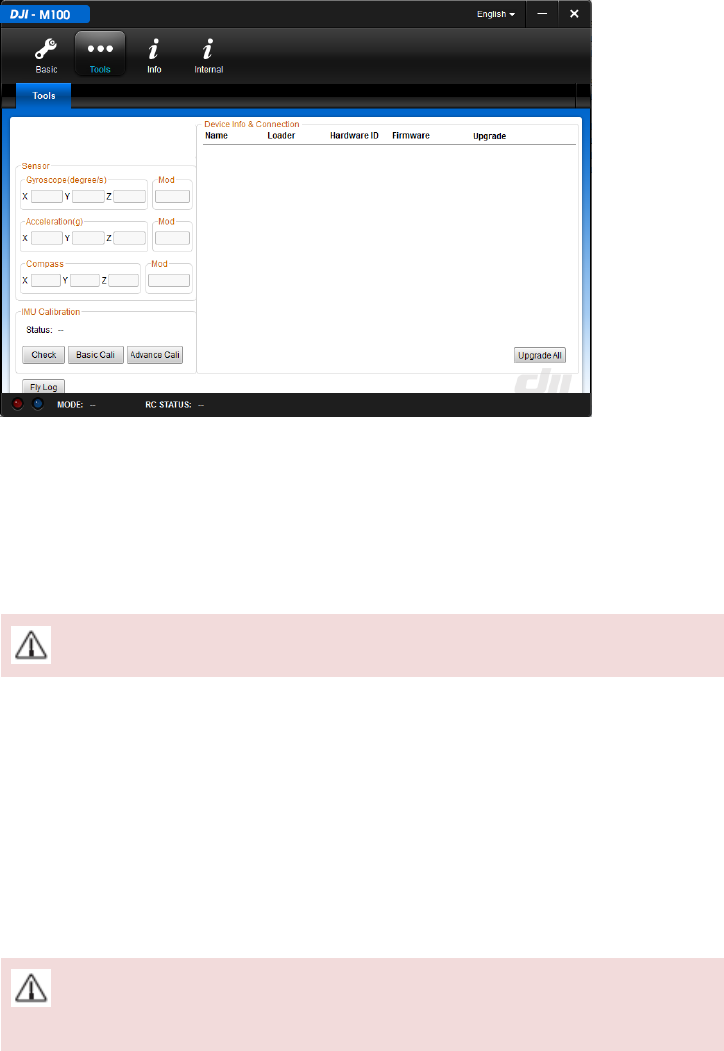
Tools Page:
1) ‘Sensor’ Section
View information on the gyroscope, acceleration and compass.
2) ‘IMU Calibration’ Section
Calibrate the IMU according to the gyroscope and acceleration sensor readings. Calibration is needed when:
a. Gyroscope Mod value exceeds 1.5.
b. Acceleration Mod value is below 0.98 or exceeds 1.02.
Place the aircraft on an even, flat surface when calibrating.
3) ‘Device Info & Connection’ Section
View the firmware version in this section. Click links to upgrade. To upgrade the Remote Controller firmware, follow
the instructions below:
Disconnect the aircraft from the computer. Connect the Remote Controller to the computer and ensure that the
Remote Controller is powered on. Click links to upgrade.
4) ‘Fly Log’ Button
Maintain the connection between the aircraft and the computer. Click this button and the computer will read the
flight logs from the aircraft. Send the data to DJI Support if you have any questions. Restart the Intelligent Flight
Battery in the aircraft to use the Assistant again.
Do NOT disconnect the aircraft from the computer or power off the Intelligent Flight Battery when
copying the flight logs.
©2015 DJI. All Rights Reserved. 55
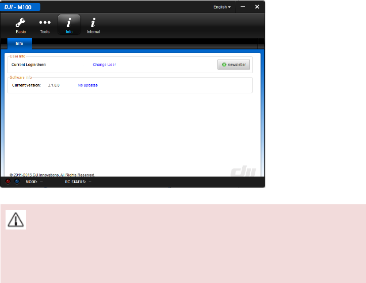
Info Page:
Change user and view the software information on this page.
The firmware version and the Assistant software version should be the same when using the software to
configure the M100, otherwise the software will not work. It is recommended to keep the firmware version and
Assistant Software version up to date to avoid this issue.

©2015 DJI. All Rights Reserved. 56
Using the SDK
Activate the Flying Platform
When “Enable API control” is enabled in the Assistant, the serial port and mode selection of the flight controller are
available. To respond to control commands from serial port, activate the flying platform as follows:
Connect the device which runs your SDK app to the aircraft. Ensure the mobile device which launches the DJI Pilot
app has access to the internet. Then the aircraft will have internet access through the Remote Controller link. Data
from the SDK app developed by users will trigger the activation procedure automatically (To do this, the functional
logic of coding should meet some requirements. Refer to the Onboard SDK Quick Start Guide for details,
http://dev.dji.com ). The SDK app itself should review and handle the activation result.
The ID of the SDK app and the SN of the aircraft will be uploaded to DJI server for recording. Other data will
not be uploaded.
©2015 DJI. All Rights Reserved. 57
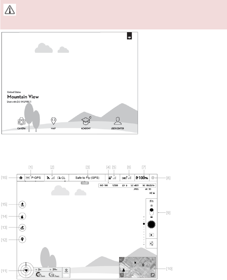
DJI Pilot App
Use this app to control the gimbal, camera and other features of your flight system. (A DJI ZENMUSE X3 Gimbal
with Camera is required when using gimbal and camera functions.) The app also comes with Map, Store a User
Center, for configuring your aircraft and sharing your content with friends. It is recommended that you use a tablet
for the best experience.
When connecting to the aircraft for the first time, ensure your mobile device has access to the internet,
and follow the instructions within the app.
Camera
The Camera page contains a live HD video feed from the camera (A DJI ZENMUSE X3 gimbal and camera is
required). You can also configure various camera parameters from the Camera page.
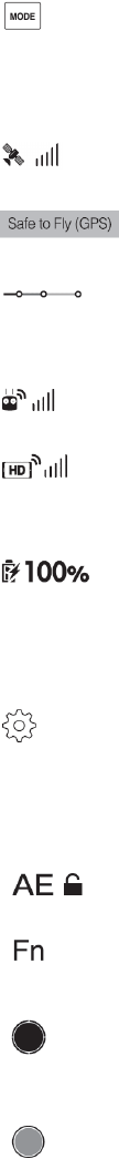
[1] Flight Mode
©2015 DJI. All Rights Reserved. 58
: The text next to this icon indicates the current flight mode.
Tap to enter MC (Main Controller) settings. Modify flight limits, perform compass calibration, and set the gain
values on this screen.
[2] GPS Signal Strength
: This icon shows the current strength of GPS signals. Green bars indicates adequate GPS strength.
[3] System Status
: This icon shows current aircraft system status, such as GPS signal health.
[4] Battery Level Indicator
: The battery level indicator dynamically displays the battery level. The color zones on the battery
level indicator represent different battery levels.
[5] Remote Controller Signal
: This icon shows the strength of remote controller signal.
[6] HD Video Link Signal Strength
: This icon shows the HD video downlink signal strength between the aircraft and the remote
controller.
[7] Battery Level
: This icon shows the current Intelligent Flight Battery level.
Tap to enter battery information menu, set the various battery warning thresholds and view the battery warning
history in this page.
[8] General Settings
: Tap this icon to enter General Settings page. Select parameter units, reset the camera, enable the quick
view feature, adjust the gimbal roll value and toggle flight route display on this page.
[9] Camera Operation Bar
Exposure Lock
: Tap to enable or disable the camera exposure lock.
Function
: Tap to adjust camera settings, such as video format and digital filters.
Shutter
: Tap this button to take a single photo.
Record
: Tap once to start recording video, then tap again to stop recording. You can also press the Video
Recording Button on the remote controller, which has the same function.
©2015 DJI. All Rights Reserved. 59
Playback
: Tap to enter playback page. You can preview photos and videos as soon as they are captured.
Camera Settings and Shooting Mode
: Tap to enter the Camera Settings page and switch from camera shooting mode from manual to auto.
[10] Map
Display the flight path of the current mission. Tap to switch from the Camera GUI to the Map GUI.
[11] Flight Telemetry
Flight Parameters:
Height: Vertical distance from home point.
Distance: Horizontal distance from home point.
Vertical Speed: Vertical flying speed.
Horizontal Speed: Horizontal flying speed.
Flight Attitude and Radar Function:
Flight attitude is indicated by the flight attitude icon.
(1) The red arrow shows which direction the aircraft is facing.
(2) Light blue and dark blue areas indicate pitch.
(3) Pitching of the boundary between light blue and dark blue area shows roll angle.
[12] Home Point Settings
: Tap this button to reset the current home point. You may choose to set the aircraft take-off location, the
remote controller’s current position, or the aircraft’s current position as the Home Point.
[13] Return to Home (RTH)
: Initiate RTH home procedure. Tap to have the aircraft return to the latest home point.

©2015 DJI. All Rights Reserved. 60
[14] Gimbal Operation Mode
Refer to “DJI ZENMUSE X3 Gimbal with Camera” under “Appendix” (P76) for more information.
[15] Auto Takeoff/Landing
: Tap to initiate auto takeoff or landing.
[16] Back
: Tap to return to the main GUI.
Map
User can view the current flight route in a larger map view in this page. You can also perform Auto take-off and
Landing in the page. Ensure your mobile device has access to the Internet. Due to the map data required, Wi-Fi
connection is recommended. Internet access is required to cache the map, if Wi-Fi is unavailable, mobile data
service is required.
Academy
Download user manual, view online videos. Also you can use the flight simulator to practice your flight skills.
User Center
You can sync the picture and videos to the mobile device, view the flight records and check your DJI account status
in the User Center. Use the DJI registered account to login to the User Center.
©2015 DJI. All Rights Reserved. 61
Flight
Once pre-flight preparation is complete, it is recommended to use the flight simulator to learn how to fly safely.
Ensure that all flights are carried out in a suitable location.
Flight Environment Requirements
1. Do not use the aircraft in severe weather conditions. These include wind speed exceeding 10m/s, snow, rain and
smog.
2. Only fly in open areas. Tall buildings and steel structures may affect the accuracy of the on-board compass and
GPS signal.
3. Avoid from obstacles, crowds, high voltage power lines, trees or bodies of water.
4. Minimize electromagnetic interference by not flying in area with high levels of electromagnetism, including
mobile phone base stations or radio transmission towers.
5. Aircraft and battery performance is subject to environment factor such as air density and temperature. Be very
careful when flying 14700 feet (4500 meters) or more above sea level as battery and aircraft performance may
be reduced.
6. The M100 cannot operate within the polar areas in “P” mode.
Flight Limits and Flight Restriction Area
Flight limits on height and distance can be set. The details of these flight limits are described in the following
section.
All unmanned aerial vehicle (UAV) operators should abide by all regulations from such organizations as the ICAO
(International Civil Aviation Organization), FAA and their own national airspace regulations. For safety reasons, the
flight limits function is enabled by default to help users use this product safely and legally. The flight limits function
includes height limits, distance limits and No Fly Zones.
When operating in P mode, height, distance limits and No Fly Zones work together to manage flight. In A mode only
height limits work and flights cannot go higher than 120 meters.
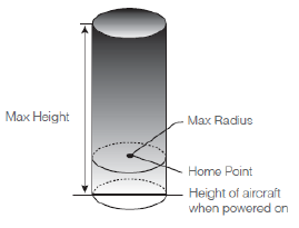
Max Height & Radius Limits
Max Height & Radius limit flying height and distance, and the user may change these settings in the DJI Pilot App.
Once complete, your M100 will fly in a restricted cylinder that is determined by these settings. The tables below
show the details of these limits.
©2015 DJI. All Rights Reserved. 62
GPS Signal Strong Blinking Green
Flight Limits DJI Pilot App Aircraft Status Indicator
Max Height Flight altitude must be
under the set height.
Warning: Height limit
reached.
None.
Max Radius Flight distance must be
within the max radius.
Warning: Distance
limit reached.
Rapid red flashing when close
to the max radius limit.
GPS Signal Weak Blinking Yellow
Flight Limits DJI Pilot App Aircraft Status Indicator
Max Height Flight height restricted to
120m and under.
Warning: Height limit
reached.
None.
Max Radius No limits
If you fly out of the limit, you can still control the M100, but cannot fly it further.
If the M100 flies out of the max radius in Ready to Fly (non-GPS) mode, it will fly back within range
automatically.
No-Fly Zones
All No-Fly Zones are listed on the DJI official website at http://flysafe.dji.com/no-fly. No-Fly Zones are divided into
Airports and Restricted Areas. Airports include major airports and flying fields where manned aircraft operate at low
altitudes. Restricted Areas include borders between countries or sensitive sites. The details of the No-Fly Zones are
explained below:
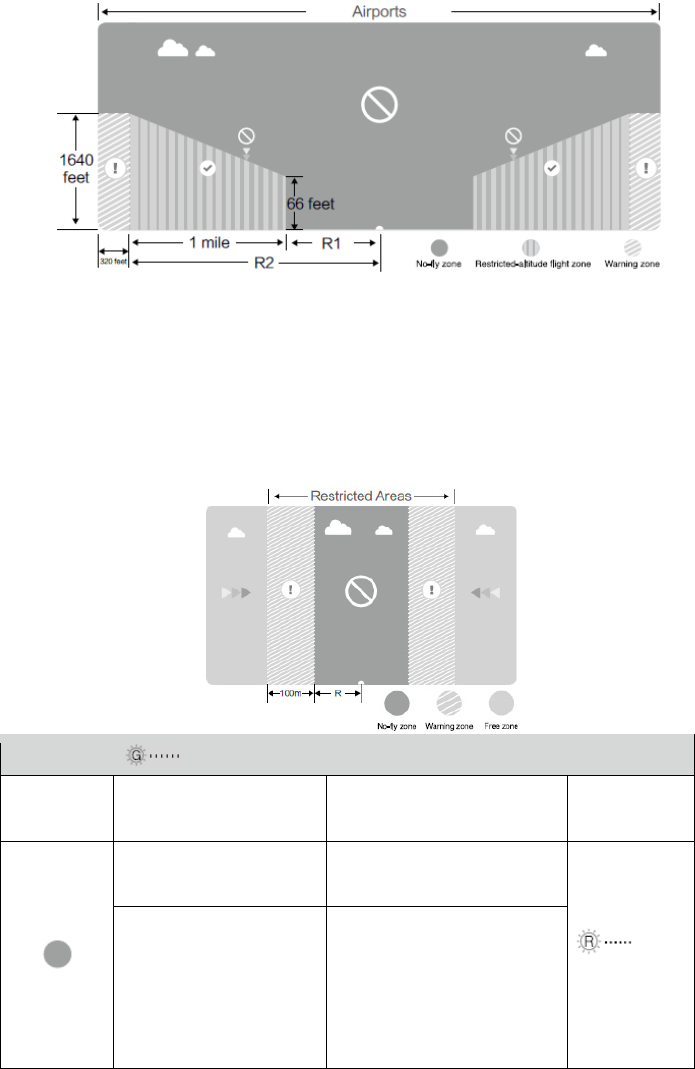
Airport:
(1) Airport No-Fly Zones are comprised of Takeoff Restricted Zones and Restricted-Altitude Zones. Each zone
features circles of various size.
(2) R1 depends on the size and shape of the airport, and is an area around the airport that is a Takeoff Restricted
Zone, inside of which take-off and flight is prevented.
(3) From R1 to R1+1 mile around the airport, the flight altitude is limited on a 15 degree incline, starting at 65 feet (20
meters) from the edge of airport and radiating outward. The flight altitude is limited to 1640 feet (500 meters) at
R1+1 mile.
(4) When the aircraft is within 320 feet (100 meters) of the No-Fly Zones, a warning message will appear in the DJI
Pilot app.
©2015 DJI. All Rights Reserved. 63
Restricted Areas:
(1) Restricted Areas do not have a flight altitude restriction.
(2) R around the designated Restricted Area is a Take-off Restricted Area. Aircraft cannot takeoff within this zone.
The value of R varies depending on the definition of the Restricted Area.
(3) A “warning zone” has been set around each Restricted Area. When the aircraft is within 0.6 miles (1 km) of this
zone, a warning message will appear in the DJI Pilot app.
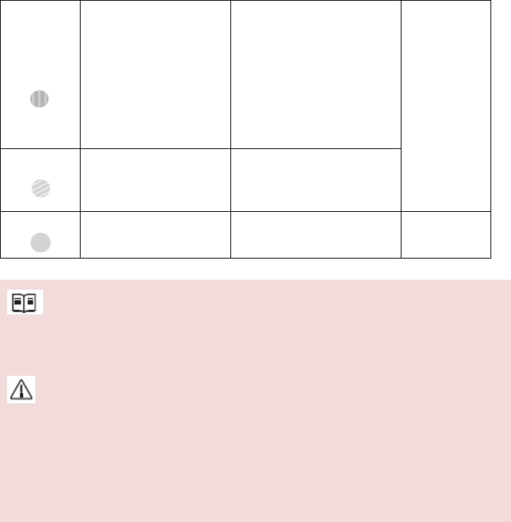
GPS Signal Strong Blinking Green
Zone Restriction DJI Pilot App Prompt Aircraft Status
Indicator
No-fly Zone
Motors will not start. Warning: You are in a No-fly zone.
Take off prohibited.
Red flashing
If the aircraft enters the
restricted area in A mode but
P mode activates the aircraft
will automatically descend to
land then stop its motors after
landing.
Warning: You are in a No-fly zone,
automatic landing has begun. (If
you are within 1.5 mile
radius)
©2015 DJI. All Rights Reserved. 64
Restricted-
altitude flight
zone
If the aircraft enters the
restricted area in A mode but
P mode activates, it will
descend to a safe altitude and
hover 15 feet below the safe
altitude.
Warning: You are in a restricted
zone. Descending to safe altitude.
(If you are between the range of 1.5
mile and 5 mile radius)
Warning: You are in a restricted
zone. Max flight height restricted
to between 10.5m and 120m. Fly
Cautiously.
Warning zone
No flight restriction applies,
but there will be warning
message.
Warning: You are approaching a
restricted zone, Fly Cautiously.
Free zone
No restrictions. None. None.
Semi-automatic descent: All stick commands are available except the throttle stick command during the descent
and landing process. Motors will stop automatically after landing.
When flying in the safety zone, aircraft status indicator will blink red quickly and continue for 3 seconds, then
switch to indicate current flying status and continue for 5 seconds at which point it will switch back to red
blinking.
For safety reasons, please do not fly close to airports, highways, railway stations, railway lines, city centers and
other special areas. Try to ensure the aircraft is visible.
Preflight Checklist
1. Remote controller, aircraft battery, and mobile device are fully charged.
2. Propellers are mounted correctly and firmly.
3. Motors can start and are functioning as normal.
4. DJI Pilot app connected to the aircraft.
Flight Status Indicator
The M100 comes with the Front LED, Rear LED and Aircraft Status Indicator. The positions of these LEDs are
shown in the figure below:
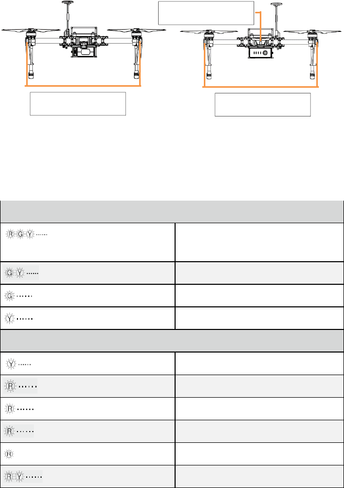
©2015 DJI. All Rights Reserved. 65
The Front and Rear LED show the orientation of the aircraft. The Front LED displays solid red and the Rear LED
displays solid green.
Aircraft Status Indicator shows the system status of the flight controller. Refer to the table below for more
information about the Aircraft Status Indicator:
Aircraft Status Indicator Description
Normal
Red, Green and Yellow Flash
Alternatively
Power on and self-check
Green and Yellow Flash Alternatively Aircraft warming up
Green Flashes Slowly Safe to Fly (P mode with GPS)
Yellow Flashes Slowly Safe to Fly (A mode but No GPS)
Warning
Fast Yellow Flashing Remote Controller Signal Lost
Slow Red Flashing Low Battery Warning
Fast Red Flashing Critical Low Battery Warning
Red Flashing Alternatively IMU Error
— Solid Red Critical Error
Red and Yellow Flash Alternatively Compass Calibration Required
Calibrating the Compass
IMPORTANT: Make sure to calibrate the compass in every new flight location. The compass is very sensitive to
electromagnetic interference, which can cause abnormal compass data leading to poor flight performance or even
failure. Regular calibration is required for optimum performance.
Front LED Rear LED
Aircraft Status Indicator
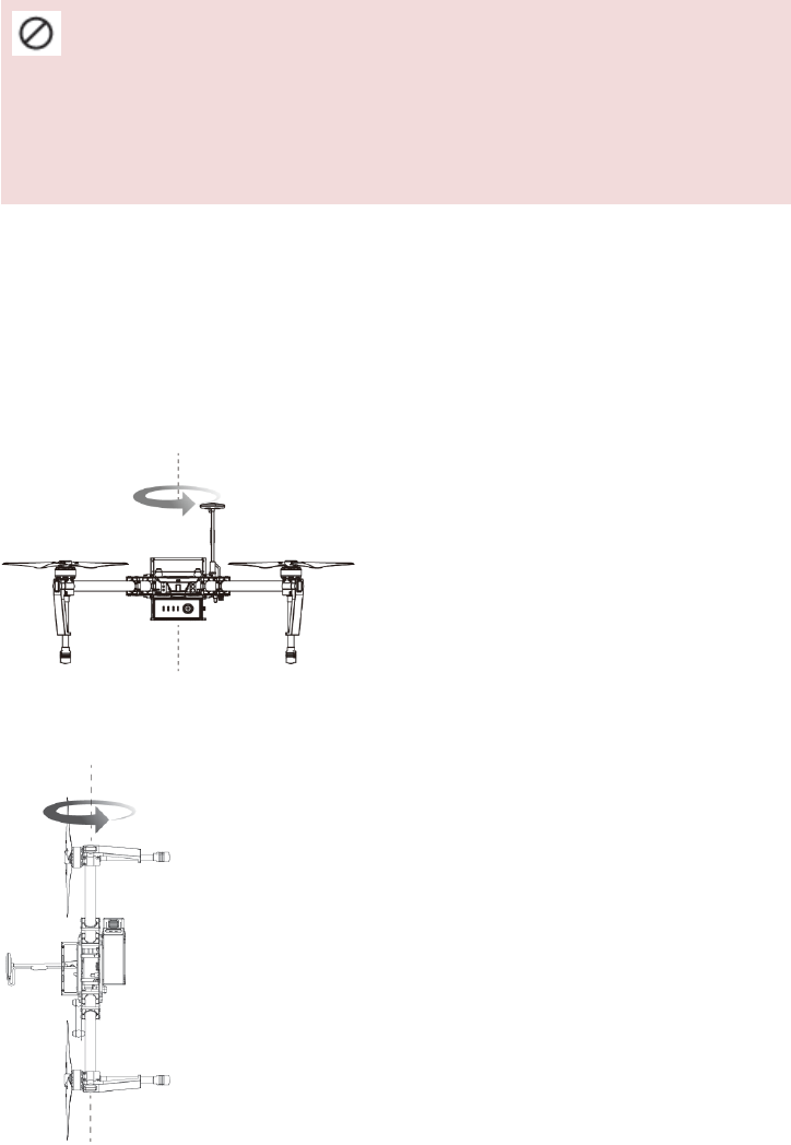
©2015 DJI. All Rights Reserved. 66
DO NOT calibrate your compass where there is a chance of strong magnetic interference, such as magnetite,
parking structures, and steel reinforcements underground.
DO NOT carry ferromagnetic materials with you during calibration such as keys or cellular phones.
DO NOT calibrate beside massive metal objects.
Calibration Procedures
Choose an open space to carry out the following procedures.
1. Ensure the compass is calibrated. If you did not calibrate the compass in the Checklist, or if you have changed
your position since last calibrating it, tap “MODE” in the app and select “Compass Calibration” to calibrate the
compass. Then follow the on-screen instructions.
2. Hold and rotate the aircraft horizontally 360 degrees, and the Aircraft Status Indicator will display a solid green
light.
3. Hold the aircraft vertically with nose pointing downward, and rotate it 360 degrees around the center axis.
Recalibrate the compass if the Aircraft Status Indicator show solid red.
©2015 DJI. All Rights Reserved. 67
If the Aircraft Status Indicator blinks red and yellow after the calibration, move your aircraft to a different
location to carry out compass calibration.
Calibrate the compass before each flight. Launch DJI Pilot App, follow the on-screen instruction to calibrate the
compass.
When to Recalibrate
1. When compass data is abnormal, and the Aircraft Status Indicator is blinking red and yellow.
2. When flying in a new location, or a location that is different from your last flight.
3. When the mechanical structure of the M100 has changed, i.e. changed mounting position of the compass.
4. When severe drifting occurs in flight, i.e. the M100 does not fly in straight lines.
Auto Take-off and Auto Landing
Auto Take-off
Use auto take-off to take off your aircraft automatically if the Aircraft Status Indicator displays blinking green.
Follow the steps below to use auto take-off:
1. Launch DJI Pilot app, enter “Camera” page.
2. Ensure the aircraft is in “P” mode.
3. Go through the pre-flight checklist.
4. Tap“ ”, and confirm flight condition. Slide to confirm and take-off.
5. Aircraft takes off and hovers at 1.5 meters above ground.
Auto-Landing
Use auto-landing to land your aircraft automatically if the Aircraft Status Indicator displays blinking green. Follow
the steps below to use auto-landing:
1. Ensure the aircraft is in “P” mode.
2. Check the landing area condition before tapping “ ”, to perform landing.
3. Aircraft lowers the landing gear and proceed to land automatically.
Starting/Stopping the Motors
Starting Motors
The Combination Stick Command (CSC) listed below are used to start the motors instead of simply pushing the
stick up. Ensure that you perform the CSC in one motion.
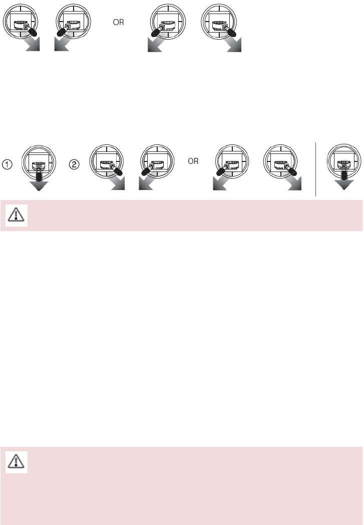
©2015 DJI. All Rights Reserved. 68
Stopping Motors
There are two methods to stop the motors.
Method 1: When the M100 has landed, push the throttle down, then conduct CSC. Motors will stop immediately.
Release both sticks once motors stop.
Method 2: When the aircraft has landed, push the throttle down and hold. The motors will stop after 3 seconds.
Do not perform CSC when aircraft is in midair, otherwise the motors will be stopped.
Flight Test
Take off/Landing Procedures
1. Place the aircraft on open, flat ground with battery indicators facing towards you.
2. Power on the remote controller and your mobile device, then the Intelligent Flight Battery.
3. Launch the DJI Pilot App and enter the Camera page.
4. Wait until the Aircraft Indicator blinks green. This means the Home Point is recorded and it is safe to fly now. If it
flashes yellow, it means Home Point is not recorded, and you should not take off.
5. Push the throttle up slowly to take off or using Auto Take-off to take off.
6. Shoot photos and videos using the DJI Pilot app.
7. To land, hover over a level surface and gently pull down on the throttle slowly to descend.
8. After landing, execute the CSC command or hold the throttle at its lowest position for 3 seconds or more until
the motors stop.
9. Turn off the Intelligent Flight Battery first, followed by the Remote Controller.
When the Aircraft Status Indicator blinks yellow rapidly during flight, the aircraft has entered Failsafe mode.
A low battery level warning is indicated by the Aircraft Status Indicator blinking red slowly or rapidly during
flight.

©2015 DJI. All Rights Reserved. 69
Appendix
Specifications
Structure
Diagonal Wheelbase 650 mm
Max. Dimensions (without GPS module) 842x842x230 mm
Weight (with TB47D battery) 2355 g
Weight (with TB48D battery) 2431 g
Max. Weight of Payload 3400 g
Optional Accessories
Expansion Bay Weight 45 g
Battery Compartment Weight 160 g
ZENMUSE X3 Gimbal with Camera Weight 247 g
Performance
Hovering Accuracy (P Mode) Vertical: 0.5 m, Horizontal: 2.5 m
Max. Angular Velocity Pitch: 300°/s, Yaw: 150°/s
Max. Tilt Angle 35°
Max. Ascent Speed 5 m/s
Max. Descent Speed 4 m/s
Max. Wind Speed Resistance 10 m/s
Max. Speed
22 m/s (ATTI mode, no wind)
15 m/s (GPS mode, no payload, no wind)
Hovering Time (with TB47D battery)
No payload: 22 min, with payload of 500 g: 17 min,
with payload of 1 kg: 13 min
Hovering Time (with TB48D battery)
No payload: 28 min, with payload of 500 g: 20
min, with payload of 1 kg: 16 min
Hovering Time (with two TB47D batteries) No payload: 33 min

©2015 DJI. All Rights Reserved. 70
Hovering Time (with two TB48D battery) No payload: 40 min
Hovering Time (with TB47D battery and ZENMUSE X3) No payload: 19 min
Hovering Time (with TB47D battery and ZENMUSE X3) No payload: 23 min
* The hovering time data is based on no-wind environment, hovering at 10 m above the sea level until landing with a battery level
of 10%
Propulsion System
Motor Model DJI 3510
Propeller Model DJI 1345s
ESC Model DJI E SERIES 620D
Flight Control System
Model N1
Other
Operating Temperature Range -10 to 40°C
Remote Controller
Name C1
Operating Frequency
922.7MHz~927.7 MHz (Japan Only)
5.725~5.825 GHz; 2.400~2.483 GHz
Transmitting Distance 2 km (Outdoor and Unobstructed)
Video Output Port USB, Mini-HDMI
Power Supply Built-in battery
Charging DJI charger
Mobile Device Holder Tablet or Smart Phone
Output Power 9 W
Operating Temperature Range -10 to 40°C

©2015 DJI. All Rights Reserved. 71
Storage Temperature Range
Less than 3 months: -20 to 45°C
More than 3 months: 22 to 28°C
Charging Temperature Range 0 to 40°C
Battery 6000 mAh LiPo 2S
Charger
Model A14-100P1A
Voltage 26.3 V
Rated Power 100 W
Battery (Standard)
Name Intelligent Flight Battery
Model TB47D
Capacity 4500 mAh
Voltage 22.2 V
Battery Type LiPo 6S High voltage battery
Energy 99.9 Wh
Net Weight 600 g
Operating Temperature Range -10 to 40°C
Storage Temperature Range
Less than 3 months: -20 to 45°C
More than 3 months: 22 to 28°C
Charging Temperature Range 0 to 40°C
Max Charging Power 180 W
Battery (Optional)
Name Intelligent Flight Battery
Model TB48D
Capacity 5700 mAh
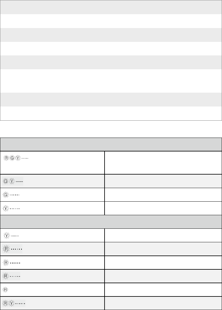
©2015 DJI. All Rights Reserved. 72
Voltage 22.8 V
Battery Type LiPo 6S
Energy 129.96 Wh
Net Weight 676 g
Operating Temperature Range -10 to 40°C
Storage Temperature Range
Less than 3 months: -20 to 45°C
More than 3 months: 22 to 28°C
Charging Temperature Range 0 to 40°C
Max Charging Power 180 W
Aircraft Status Indicator Description
Normal
Red, Green and Yellow Flash
Alternatively
Power on and self-check
Green and Yellow Flash Alternatively Aircraft warming up
Green Flashes Slowly Safe to Fly (P mode with GPS)
Yellow Flashes Slowly Safe to Fly (A mode but No GPS)
Warning
Fast Yellow Flashing Remote Controller Signal Lost
Slow Red Flashing Low Battery Warning
Fast Red Flashing Critical Low Battery Warning
Red Flashing Alternatively IMU Error
— Solid Red Critical Error
Red and Yellow Flash Alternatively Compass Calibration Required
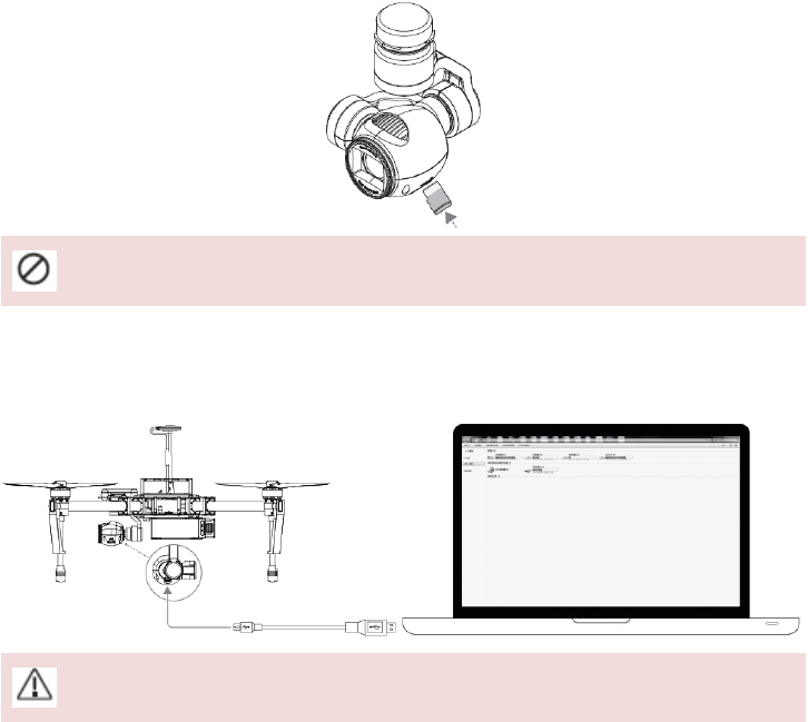
©2015 DJI. All Rights Reserved. 73
DJI ZENMUSE X3 Gimbal with Camera
Camera Profile
The on-board camera supports 4K video capture up to 4096x2160p24 and 12M pixel photos capture by using the
1/2.3 inch CMOS sensor. You may export the video in either MOV or MP4 format for editing. Available picture
shooting modes include burst, continuous, and timer mode. A live preview of what the camera is seeing before you
shoot videos and pictures is supported through the DJI Pilot App.
Camera Micro-SD Card Slot
To store your photos and videos, plug in the micro-SD card into the slot shown below before powering on the M100.
The camera supports up to a 64GB micro-SD card. A UHS-1 type micro-SD card is recommended, because the fast
read and write capability of these cards enables you to store high-resolution video data.
Do not remove micro-SD card from the M100 when it is powered on.
Camera Data Port
Power on the M100 and then connect a USB cable to the Camera Data Port to download photos or videos from the
camera to your computer.
Power on the aircraft before attempting to download the files.
Camera Operation
Use the Shutter and Record button on the remote controller to shoot the images or the videos through the
DJI Pilot app. For more information about how to use these buttons, refer to “Controlling Camera” P44.
ND Filter
Attach an ND filter to the front of the camera to reduce over-exposure and “jello” effect.
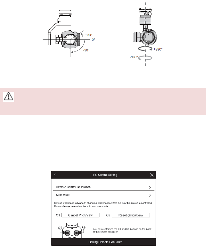
©2015 DJI. All Rights Reserved. 74
Gimbal
Gimbal Profile
The 3-axis Gimbal provides a steady platform for the attached camera, allowing you to capture stabilized images
and video. The Gimbal can tilt the camera up to 120 degrees and rotate 360 degrees.
Use the gimbal dial on the remote controller to control pitch movement of the camera by default. Note that you
cannot control the pan motion of the camera by default.
Use the gimbal dial on the remote controller to control the pitch movement of the camera, however, you
cannot control the pan movement of the camera.
Pan Control
Follow the instructions below to use the gimbal dial to control the pan movement of the gimbal:
1. Power on the aircraft and remote control, launch DJI Pilot app and enter “Camera” page.
2. Tap “RC Control Settings” icon and select either C1 or C2 customizable button as the gimbal pitch/yaw switching
button.
3. Select “Gimbal Pitch/Yaw” from the dropdown list.
Press C1 or C2 button to switch from pitch mode to yaw mode. You may use the gimbal dial to pan the gimbal under
yaw mode. Press C1 or C2 again to exit yaw mode.
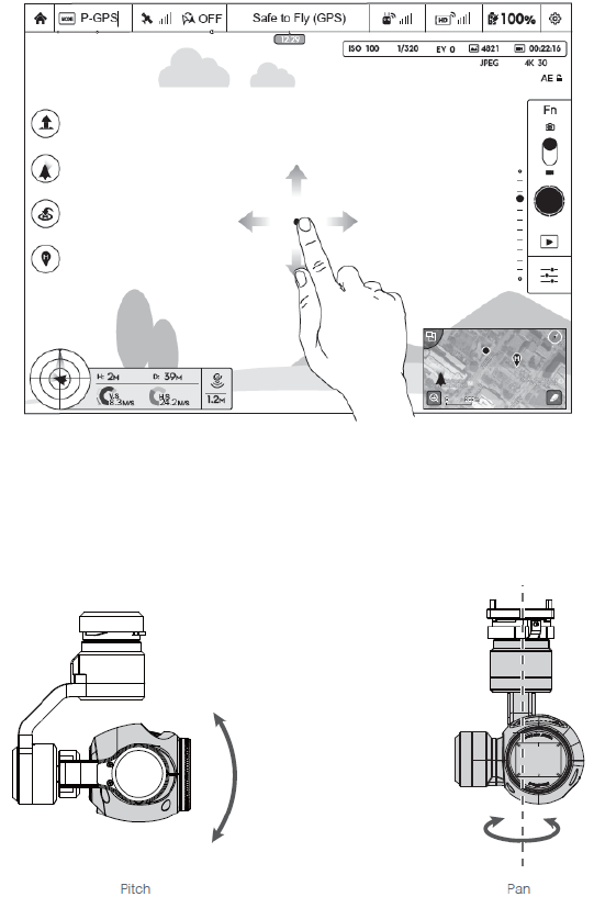
©2015 DJI. All Rights Reserved. 75
Using DJI Pilot App to Control Gimbal
Follow the steps below to use DJI Pilot app to control the gimbal orientation:
1. Launch DJI Pilot app, enter “Camera” page.
2. Tap and press on the screen until a blue circle is shown.
3. Slide to control the gimbal orientation within the “Camera” page as shown below.
Gimbal Operation Modes
Three Gimbal operation modes are available. Switch between the different operation modes on the Camera page of
the DJI Pilot App. Note that your mobile device must be connected to the remote controller for changes to take
effect. Refer to the table below for details:
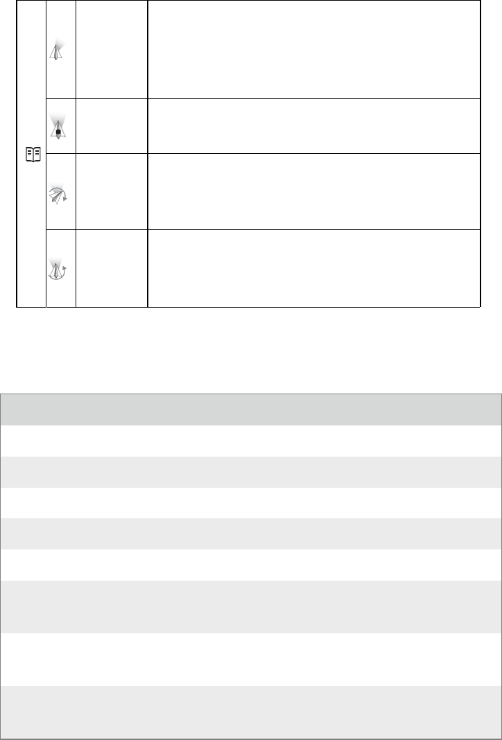
©2015 DJI. All Rights Reserved. 76
Follow Mode
The angle between Gimbal’s orientation and aircraft’s nose remains
constant at all times. One user alone can control the pitch motion of the
Gimbal, but a second user is required to control the pan motion using a
second remote controller.
FPV Mode
The Gimbal will lock to the movements of the aircraft to provide a
First-Person-View flying experience.
Free Mode
The Gimbal’s motion is independent of the aircraft’s orientation. One
user alone can control the pitch motion of the Gimbal, but a second user
is required to control the pan motion using a second remote controller.
Re-ali
g
nment
Tap to force the Gimbal orientation to re-align with aircraft’s orientation
by panning from gimbal’s current orientation. Pitch angle will remain
unchanged during the re-alignment.
Specifications
Gimbal
Model ZENMUSE X3
Output Power (With Camera) Static: 9 W; In Motion: 11 W
Operating Current Station: 750 mA; Motion: 900 mA
Angular Vibration Range ±0.03°
Mounting Detachable
Controllable Range
Pitch: -90° to +30°
Pan: ±320°ã
Mechanical Range
Pitch: -125°ã to +45°ã
Pan: ±320°
Max Controllable Speed
Pitch: 120°/s
Pan: 180°/s

©2015 DJI. All Rights Reserved. 77
Camera
Name X3
Model FC350
Total Pixels 12.76M
Effective Pixels 12.4M
Image Max Size 4000x3000
ISO Range 100-3200 (video) 100-1600 (photo)
Electronic Shutter Speed 8 s to 1/8000 s
FOV (Field Of View) 94°ã
CMOS Sony EXMOR 1/2.3¡±
Lens
20mm (35mm format equivalent) f/2.8 focus at )
9 Elements in 9 groups
Anti-distortion
Still Photography Modes
Single shoot
Burst shooting: 3/5/7 frames
Auto Exposure Bracketing (AEB): 3/5 bracketed frames at 0.7EV Bias
Time-lapse
Video Recording Modes
UHD (4K): 4096x2160p24/25, 3840x2160p24/25/30
FHD: 1920x1080p24/25/30/48/50/60
HD: 1280x720p24/25/30/48/50/60
Max Bitrate Of Video Storage 60 Mbps
Supported File Formats
FAT32/exFAT
Photo: JPEG, DNG
Video: MP4/MOV (MPEG-4 AVC/H.264)
Supported SD Card Types
Micro SD
Max capacity: 64 GB. Class 10 or UHS-1 rating required.
Operating Temperature Range 0ã to 40°ãC
©2015 DJI. All Rights Reserved. 78
Compliance Information
FCC Warning Message
Any Changes or modifications not expressly approved by the party responsible for compliance could void the
user’s authority to operate the equipment.
This device complies with part 15 of the FCC Rules. Operation is subject to the following two conditions: (1) This
device may not cause harmful interference, and (2) this device must accept any interference received, including
interference that may cause undesired operation.
FCC Radiation Exposure Statement:
This devices complies with FCC radiation exposure limits set forth for an uncontrolled environment. This
M100 should be installed and operated with minimum distance 20cm between the radiator& your body. This
transmitter must not be co-located or operating in conjunction with any other antenna or transmitter
Note: This equipment has been tested and found to comply with the limits for a Class B digital device, pursuant to
part 15 of the FCC Rules. These limits are designed to provide reasonable protection against harmful interference in
a residential installation. This equipment generates uses and can radiate radio frequency energy and, if not installed
and used in accordance with the instructions, may cause harmful interference to radio communications. However,
there is no guarantee that interference will not occur in a particular installation. If this equipment does cause
harmful interference to radio or television reception, which can be determined by turning the equipment off and on,
the user is encouraged to try to correct the interference by one or more of the following measures:
—Reorient or relocate the receiving antenna.
—Increase the separation between the equipment and receiver.
—Connect the equipment into an outlet on a circuit different from that to which the receiver is connected.
—Consult the dealer or an experienced radio/TV technician for help.
IC RSS warning
This device complies with Industry Canada licence-exempt RSS standard (s). Operation is subject to the following
two conditions: (1) this device may not cause interference, and (2) this device must accept any interference,including
interference that may cause undesired operation of the device.
Le présent appareil est conforme aux CNR d'Industrie Canada applicables aux appareils radio exempts de licence.
L'exploitation est autorisée aux deux conditions suivantes:
(1) l'appareil ne doit pas produire de brouillage, et
(2) l'utilisateur de l'appareil doit accepter tout brouillage radioélectrique subi, même si le brouillage est susceptible
d'en compromettre le fonctionnement.
©2015 DJI. All Rights Reserved. 79
IC Radiation Exposure Statement:
This equipment complies with IC RF radiation exposure limits set forth for an uncontrolled environment. This
transmitter must not be co-located or operating in conjunction with any other antenna or transmitter.
This M100 should be installed and operated with minimum distance 20cm between the radiator& your body.
Any Changes or modifications not expressly approved by the party responsible for compliance could void the
user’s authority to operate the equipment.
KCC Warning Message
“해당무선설비는 운용 중 전파혼신 가능성이 있으므로 인명안전과 관련된 서비스는 할 수 없습니다.”
“해당 무선설비는 운용 중 전파혼신 가능성이 있음”
NCC Warning Message
低功率電波輻射性電機管理辦法
第十二條經型式認證合格之低功率射頻電機,非經許可,公司、商號或使用者均不得擅自變更頻率、加
大功率或變更原設計之特性及功能。
第十四條低功率射頻電機之使用不得影響飛航安全及干擾合法通信;經發現有干擾現象時,應改善至無
干擾時方得繼續使用。前項合法通信,指依電信法規定作業之無線電通信。低功率射頻電機須忍受合法
通信或工業、科學及醫療用電波輻射性電機設備之干擾。

©2015 DJI. All Rights Reserved. 80
The content is subject to change.
Download the latest version from
www.dji.com/support