Saab Defense and Security USA SID915 STRUCTURAL INFORMATION DEVICE User Manual
Saab Defense and Security USA LLC STRUCTURAL INFORMATION DEVICE
User Manual
User
Guide
Urban Training Package
incl.
MILES
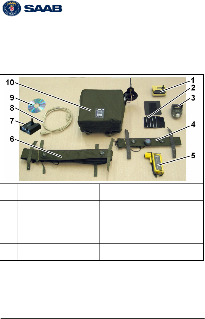
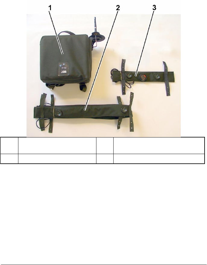
1 Overview
1
Structure Information De-
vice (SID)
6
SES Detector belt (option)
2
Installation kit (plate/velcro)
7
WLN Adapter II
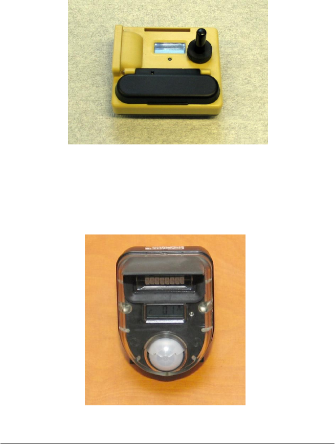
3
Room Association Device
(RAD)
8
Cable WLN Adapter - AAR
Computer
4
SES Detector/Reflector belt
(option)
9
Installation CD with WinEx-
con Building Setup Tool
5
CGUN
10
Structure Effects Simulator
(SES) (option)
© Saab Training Systems Final 2 8875 801-339
2
2 System Description
The Urban Training Package is a upgrade kit to facilitate instrumented
tactical urban training and enable instrumented players to be tracked
inside buildings where normally they cannot receive a GPS signal. The
package permits the simulation of indirect and direct fires on building
occupants taking in to account varying levels of structural ballistic
protection.
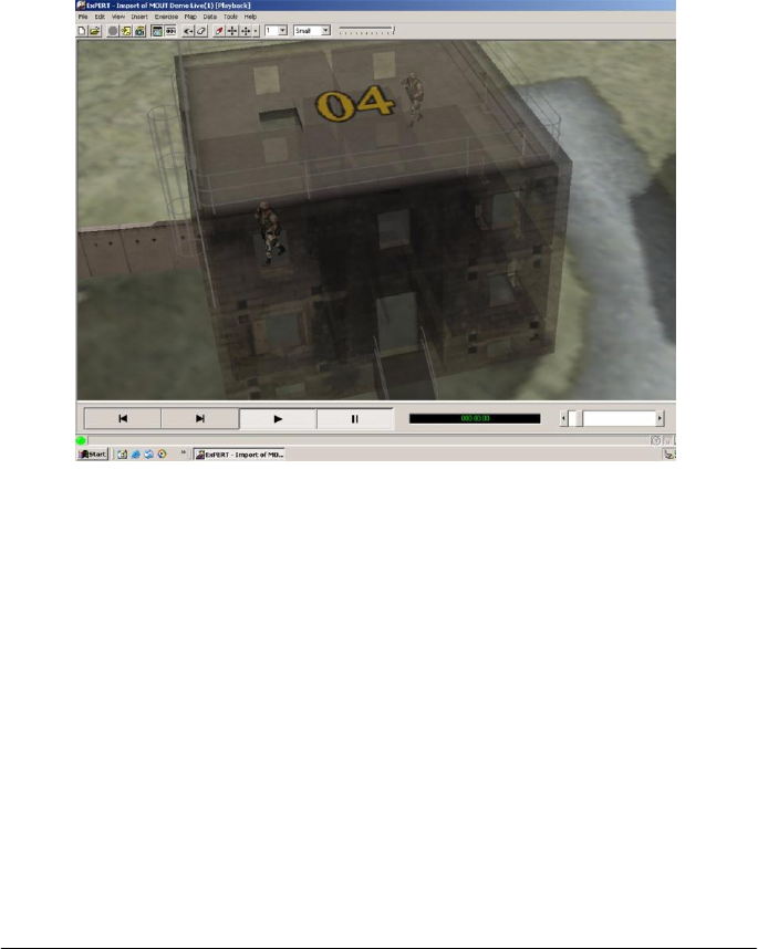
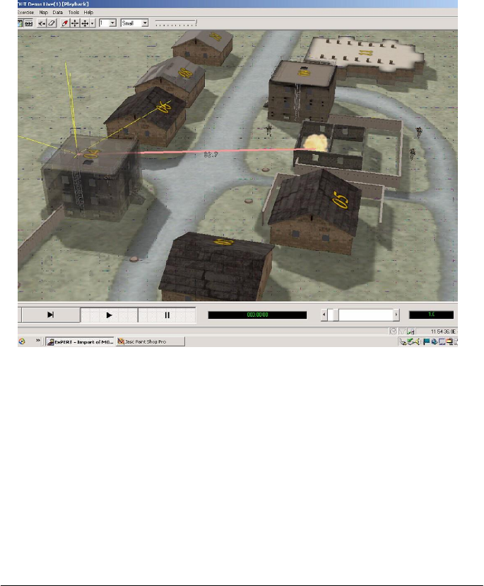
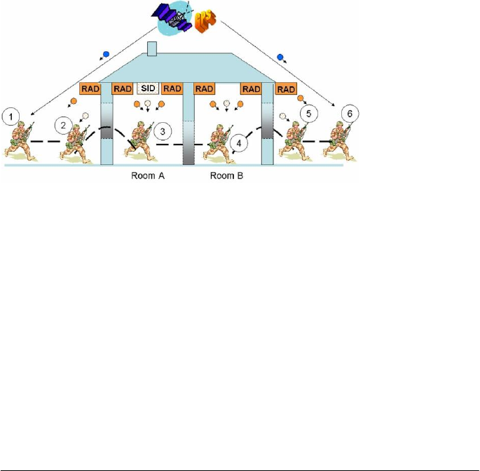
3
The system is designed for tactical urban training, typically up to
company level. At the tactical level, instrumented players are depicted
centrally in the room they occupy but not exactly where within the
room. An instrumented urban exercise is viewed via the Command
and Control C2 computer console in real time or in the AAR replay.
The exercise map/aerial photo of the urban training area in the C2
node requires a 2D or 3D depiction of the site buildings to be loaded.
The Urban Training Package is made up of three primary devices:
• Structural Information Device (SID)
• Room Association Device (RAD)
• Structure Effects Simulator (SES)
Structural Information Device (SID)
The SID is a short range radio device that is used to transmit
programmed building characteristics to instrumented players in the
vicinity prior to them entering the building. The Personnel Detection
Device (PDD) worn by a player receives data from the SID regarding
the following:
• Synthetic GPS positions of rooms, stair wells and corridors
• The ballistic protection of each room or zone for simulated indirect
or direct fires
4
A SID is placed in each building of interest in an urban exercise where
players are required to be tracked. A SID is programmed with the
building characteristics via a software Building Setup Tool loaded in to
a laptop and data transfer device called a WLN Adapter. Setup
information is contained in Chapter 4.
Room Association Device (RAD)
The RAD is used to identify which room or zone an instrumented
player has entered. It sends out a unique optical code to the PDD and
this data is compared with the stored SID data to establish which room
or zone the player is in. RADs are programmed with their location ID
via the Building Setup Tool.
5
1
Structure Effects Simula-
tor (SES)
3
SES Detector/Reflector Belt
2
SES Detector Belt
Structure Effects Simulator (SES)
The SES is a device to enable the simulation of direct fire weapons
effects simulators (DFWES) on building occupants in primary and
secondary rooms. This enables for example an instrumented sniper in
an up stairs room to be suppressed by a TWGSS or MILES 120mm
main gun engagement.
6
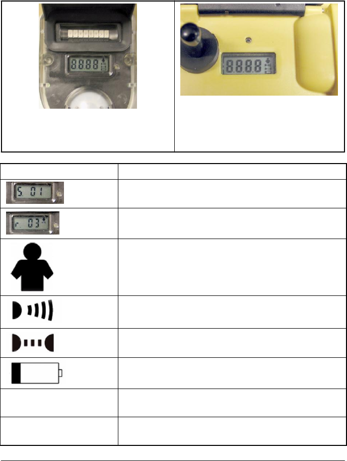
3 Display symbol description
The display symbols presented on the RAD display and on the SID
display are:
RAD Display overview
SID Display overview
(The Motion sensor symbol and the
IR communication symbol are not
available).
Display Symbol
Description
Structure ID. Identifies the selected structure/
building.
Room ID. Identifies the selected room.
Motion sensor activated (only RAD).
IR transmission activated (only RAD).
IR Communication activated.
Low battery status.
LED single red flash ev-
ery 3 seconds
Low battery status.
LED double red flash
every 3 seconds
ERROR - exchange the unit.
7
4 Setup
The player field position is based on a GPS receiver. The WinExcon
Building Setup Tool provides the player with additional data when
inside or adjacent to a building in situations when signals from the
GPS-satellites are unavailable or not reliable. The GPS position for
each room or part of a (larger) room will instead be communicated to
the player system from the added Urban Training package. This
enables the player system to react independently to AWES in the
same way as for outdoor positions. Once the player leaves the house
and has a good GPS-signal again the GPS receiver is used to position
the player. Hence the positioning technique is seamlessly integrated in
the player. The Room Association Function is implemented by Room
Association Devices (RAD) and Structure Information Devices (SID).
8
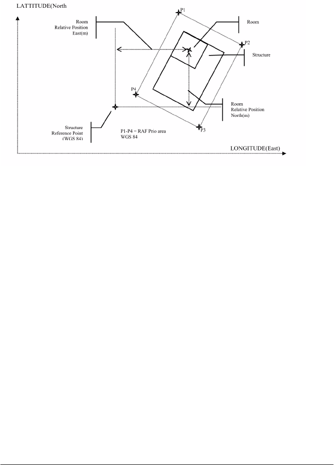
To perform Setup of the system, necessary required GPS information
and room attributes, has to be provided for chosen structure and
rooms.
The required information for each structure is:
• Reference point for each structure (GPS coordinates).
• RAF prio area for each structure (coordinates for P1 - P4). A
selected area, where the GPS is not allowed to override the Room
Association Function, when leaving building due to risk of bad GPS
coverage.
The required information for each room is:
• Relative position (north, east and altitude)
• AWES Protection (0-100%)
• Wall type (for example concrete, brick or wood)
• Room attributes (Confined Space, non Confined Space or outdoor)
1 To start the Set up program install the CD with WinExcon Building
Setup software. Or: Click the Building Setup Tool icon on the
screen.
9
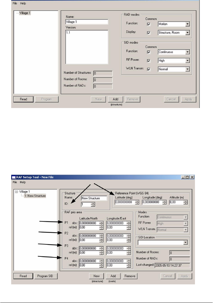
2 To create a village, select File, New. Enter Name and Version.
Click Apply.
3 To save the input, Select File, Save as. Select a File name and
select the directory or storage area. Click Save throughout the
Setup procedure continuously to prevent any information being
lost.
4 To create a structure, Click Add. Enter only required information
(ID, coordinates for Reference point and RAF prio area. Name is
optional). Click Apply.
10
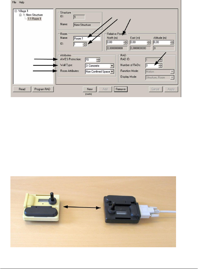
5 To create a room Click Add. Enter required information (Name, ID,
Relative position, Attributes (AWES protection, wall type and room
attributes) and number of RAD's required). Click Apply. To create
a new room, Click New.
6 To enter information about SID location, select required structure
and Click on the drop-down-list for the SID Location and select
room. Click Apply.
7 Connect the cable to the serial port on the computer.
8 Check if the battery is installed in the WLN adapter. If not, put in
the battery.
9 Connect the WLN adapter to the cable.
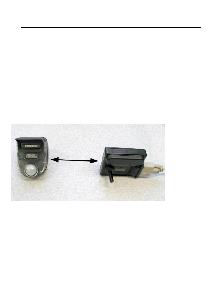
10 To prepare transferring data to the SID put the WLN adapter and
the SID close side by side with their IR windows aligned.
11
11 Check if the battery is installed in the SID. If the battery is installed,
take out the battery and wait until the display is turned off. Put in
the battery again.
Note!
A communication time limit of 30 seconds is valid for program-
ming the SID. If the time limit has exceeded, take out the battery
and wait until the SID display is turned off.
12 To program the SID, Select Structure in the Navigator, Click
Program SID. (If necessary, select Device and Port).
13 To start the transfer, Click Program . The transfer is ready when
the message "Transfer complete" is shown.
14 Remove the battery from the SID.
15 To prepare transferring data to the RAD, put the WLN adapter and
the RAD with their IR windows aligned with a distance of 20-30 cm.
Note!
Make sure the motion sensor is activated on the RAD display.
16 To program the RAD, Select Room in the selected structure in the
Navigator, Click Program RAD. (If necessary, select Device and
Port). The transfer is ready when message "Transfer complete" is
shown.
17 To print a report, Click on selected village in the Navigator and
select File, Print.
12
5 Installation
WARNING!
Battery Hazard
Follow standard procedure for use of Lithium batteries.
WARNING!
Do not install SIDs/RADs at a free-fall height greater than
3 meters. SIDs/RADs dislodged from heights greater than
3 meters may cause bodily injury.
WARNING!
Secure the SES with fastening straps when installed in a
high position.
Note!
Make sure the direction of the SID and the SES antenna is
vertical.
Note!
The SID shall be installed centrally on the ground floor in the
selected structure (building).
Note!
Minimum RAD installation height is 1.8 meters and maximum
installation height is 3 meters.
13
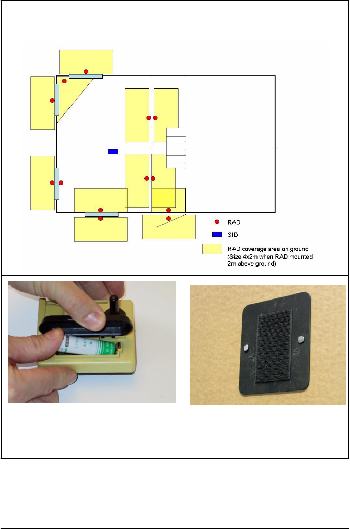
1. Install the equipment according to the installation plan .
Example of indoor and outdoor installation of RADs. The SID shall be
installed centrally on ground floor to get the optimal freuency range.
2. Take the SID and check if the
battery is installed. Make sure to use
Lithium battery 3.6V 2.25 AH LI AA.
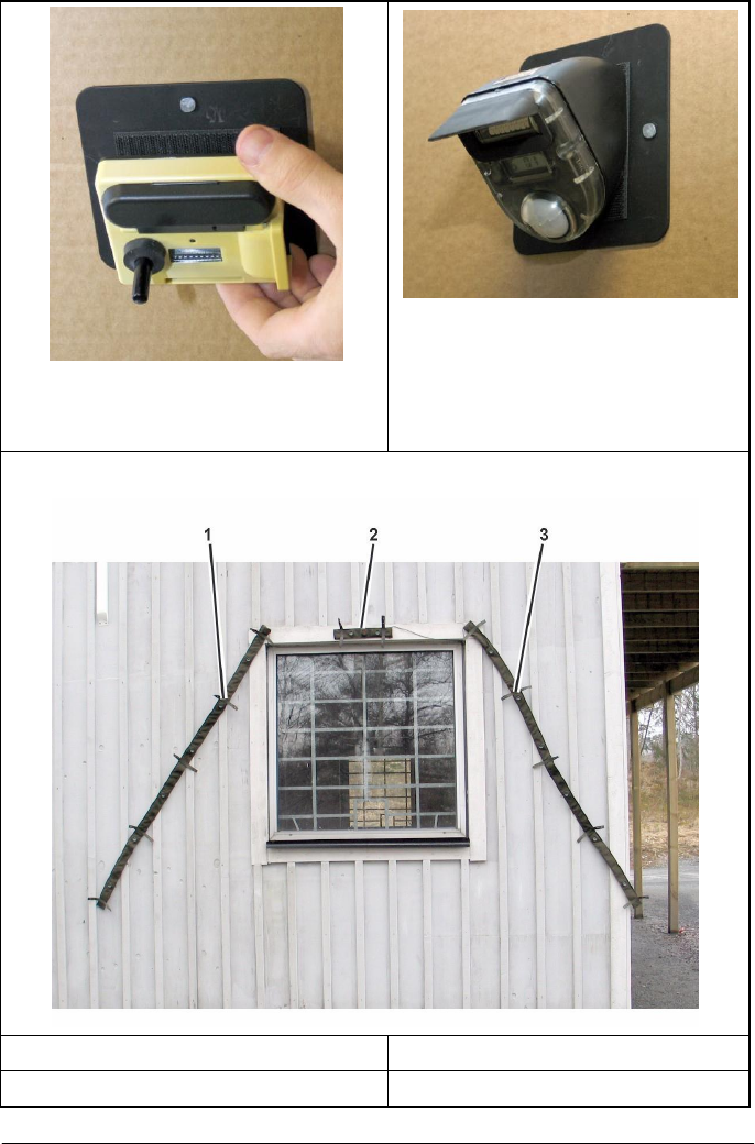
3. If necessary, prepare the
installation
of the
SID and RADs
by
installing the plate and/or velcro
kit.
14
4. Install the SID according to
information displayed on the SID
(S=structure ID and r=room ID).
5. Install the RADs according to
information displayed on the RAD
(S=structure and r=room ID).
6. Install the detector/reflector belt and the detector belts.
1. Detector belt
3. Detector belt.
2. Detector/Reflector belt
15
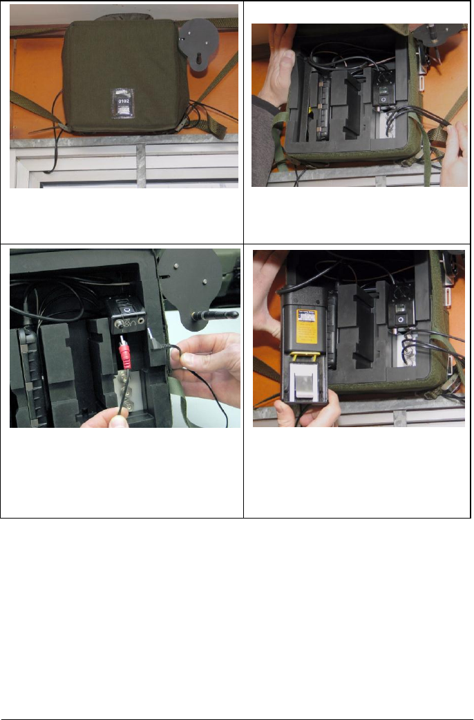
7. Install the SES in primary room.
Make sure the SID is installed and is
operating.
8. Open the SES flap and connect
the detector/reflector belts into the
SES.
9. As an option, it is possible to
connect an external speaker and a
visual hit indicator into the SES.
10a. Install Rechargeable
battery. Remove the Battery Unit
(BU) and insert the battery. Verify
that "Tampering kill" is heard from
the speaker.
16
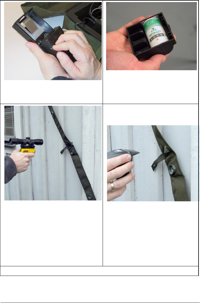
10b. Install Non-rechargeable
battery. Remove the BU. Remove
the battery holder from the BU.
10c. Put the battery in the battery
holder. Verify that "Tampering kill"
is heard from the speaker.
11. Use the CGUN and shoot a
RESET Command. Message
"RESET WALL TYPE NO" is heard
from the speaker. The speaker
confirm that wall type level in primary
room is set to default value given by
the SID. To start the configuration of
the RADs, shoot an ACCESS
Command with the CGUN.
12. The SES is generating a
"primary room" audio cue. Put one
RAD installed in primary room in
front of the laser detectors. Repeat
the procedure when SES is
generating a "secondary room"
audio cue. The SES will confirm
each Room ID.
13. Message "System OK" is heard when the system is ready.

17
6 CGUN Control Functions for
SES
During exercise the Observer/Controller has the ability to change
the wall type level for each SES individually. The changes are valid
for primary room, secondary room and adjacent room for the
specific SES.
Improve protection for a room
Use the CGUN and send the command DUG IN or RESURRECT
(MILES). The command will change the wall type for primary,
secondary and adjacent room at the same time. Repeat the
command to desired level. The speaker will confirm the new wall
type level for primary room. Maximum wall type level is 5.
Decrease protection for a room
Use the CGUN and send the command WOUNDED or KILLED
(MILES). Repeat the command to desired level. The speaker will
confirm the new wall type level for primary room. Minimum wall
type level is 1.
Reset of room
Use the CGUN and send a RESET command. The speaker will
confirm the command and the wall type level will be reset to
default value given from the SID.
Verify walltype
Use the CGUN and send the command TEST. The speaker will
confirm ID no (primary room no), time, set wall type level. Message
"System OK" will be confirmed by the speaker when the system is
ready. If message "System Error" is received, the SES unit has to
be exchanged.

18
7 Maintenance
Battery life time
SID
3.6V 2.25 AH LI AA
3 months
RAD
3V/0.85AH LI CR2
12 months
Change battery on SID and RAD when:
• The LED single red flash every 3 seconds on the SID display
and on the RAD display.
• A battery symbol is shown on the display.
No
te!
A screwdriver, Torx TX 8, is needed to open the RAD.
A continiously check of the installation kit (plate and velcro) should
be done. Exchange of the velcro should be done if needed.
8 Removal
1 Remove the RADs in each room.
2 If necessary, remove the installation kit (plate and velcro).
Check the velcro. Exchange the velcro if needed.
3 Remove the SID in each structure. Remove the battery.
4 If necessary, remove the installation kit (plate and velcro).
Check the velcro. Exchange the velcro if needed.
5 Disconnect the Detector/Reflector belts from the SES.
6 Remove the battery from the SES.
7 Remove the SES.
8 Remove the Detector/Reflector belt and the Detector belts.

19
9 Regulatory Statement
9.1 FCC Certification
The United States Federal Communication Commission (FCC) has
established certain rules governing the use of electronic equipment.
9.2 Part15, Class B
1 This system contains a device that is FCC certified, FCC ID:
R4ASID915
2 This device complies with Part 15 of FCC rules and operation and is
subject to the following two conditions:
2.1 This device may not cause harmful interference, and
2.2 This device must accept any interference received, including
interference that may cause undesired operation. This equipment has
been tested and found to comply with the limits for a Class B digital
device, pursuant to Part 15 of the FCC rules.
9.3 IC Certification
This system contains a device that is IC certified, IC: 4660D-SID915
IC RSS-GEN, Sec 7.1.3 Warning Statement- (Required for license-
exempt devices)
ENGLISH:
This device complies with Industry Canada license-exempt RSS
standard(s). Operation is subject to the following two conditions:
(1) this device may not cause interference, and
(2) this device must accept any interference, including interference that
may cause undesired operation of the device.
FRENCH:
Le présent appareil est conforme aux CNR d'Industrie Canada applicables
aux appareils radio exempts de licence. L'exploitation est autorisée aux
deux conditions suivantes :
(1) l'appareil ne doit pas produire de brouillage, et
(2) l'utilisateur de l'appareil doit accepter tout brouillage radioélectrique
subi, même si le brouillage est susceptible d'en compromettre le
fonctionnement.

20
IC RSS-GEN, Sec 7.1.2 Warning Statement- (Required for Transmitters)
ENGLISH:
Under Industry Canada regulations, this radio transmitter may only
operate using an antenna of a type and maximum (or lesser) gain
approved for the transmitter by Industry Canada. To reduce potential radio
interference to other users, the antenna type and its gain should be so
chosen that the equivalent isotropically radiated power (e.i.r.p.) is not
more than that necessary for successful communication.
FRENCH:
Conformément à la réglementation d'Industrie Canada, le présent
émetteur radio peut fonctionner avec une antenne d'un type et d'un gain
maximal (ou inférieur) approuvé pour l'émetteur par Industrie Canada.
Dans le but de réduire les risques de brouillage radioélectrique à
l'intention des autres utilisateurs, il faut choisir le type d'antenne et son
gain de sorte que la puissance isotrope rayonnée quivalente (p.i.r.e.) ne
dépassepas l'intensité nécessaire à l'établissement d'une communication
satisfaisante.
9.4 User Information
WARNING
!
Any changes or modifications not expressly approved by the party
responsible for compliance, namely Saab Defense and Security USA
LLC, could void the user's authority to operate the equipment.