Safe Zone Systems CTD1000 CONCEALED WEAPON RADAR DETECTOR User Manual CTD manual notes
Safe Zone Systems, Inc. CONCEALED WEAPON RADAR DETECTOR CTD manual notes
UserManual.wiki
>
Safe Zone Systems
>
CTD1000 User Manual
MANUAL
Navigation menu
Upload a User Manual
Namespaces
Wiki Guide
HTML
PDF
Info
Views
User Manual
Discussion / Help
Navigation
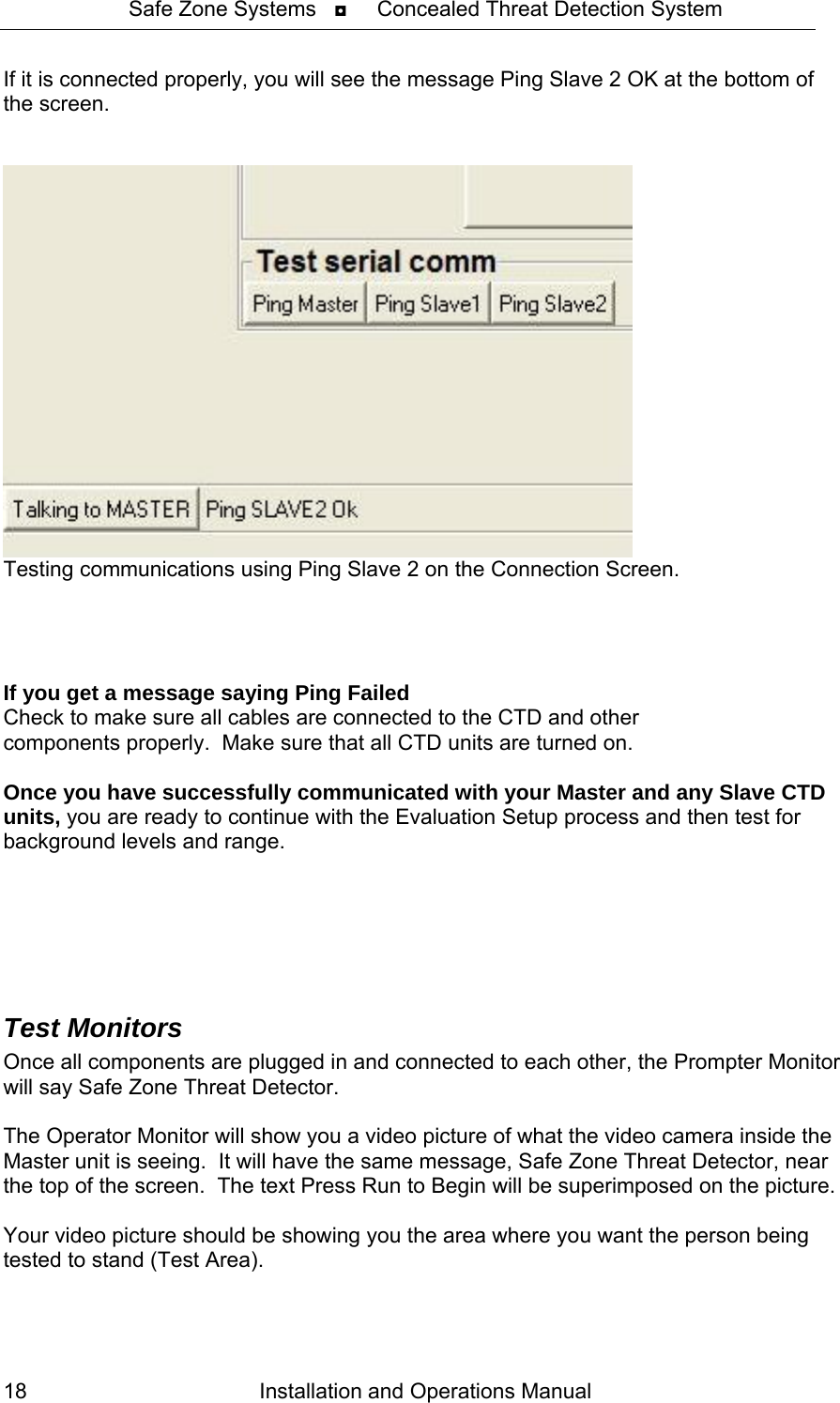
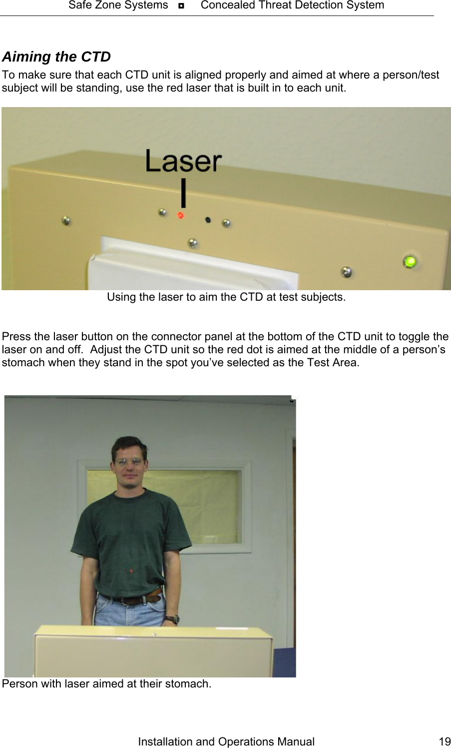
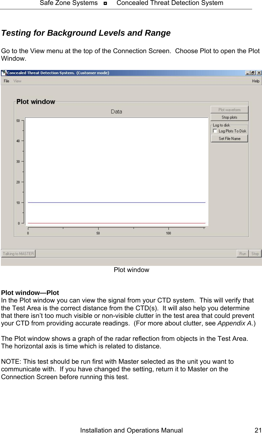
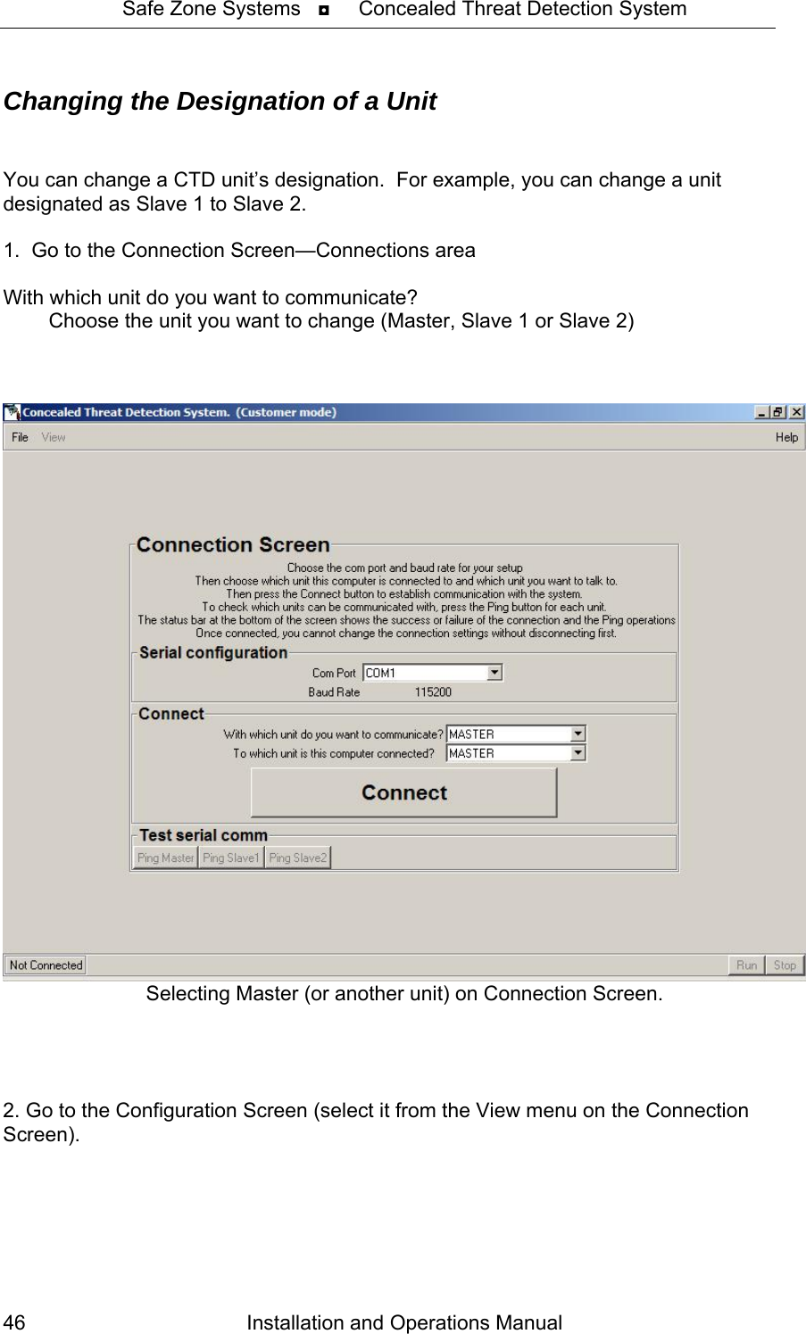
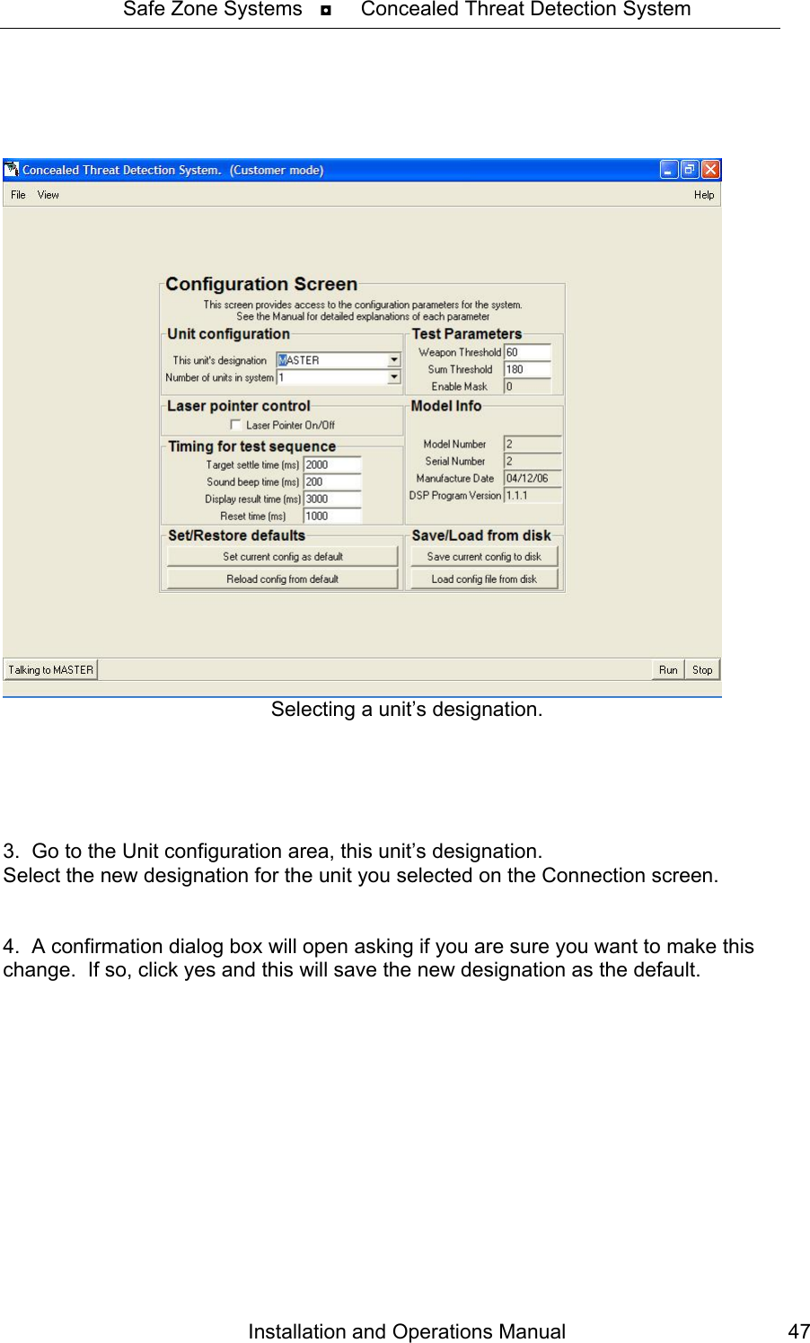
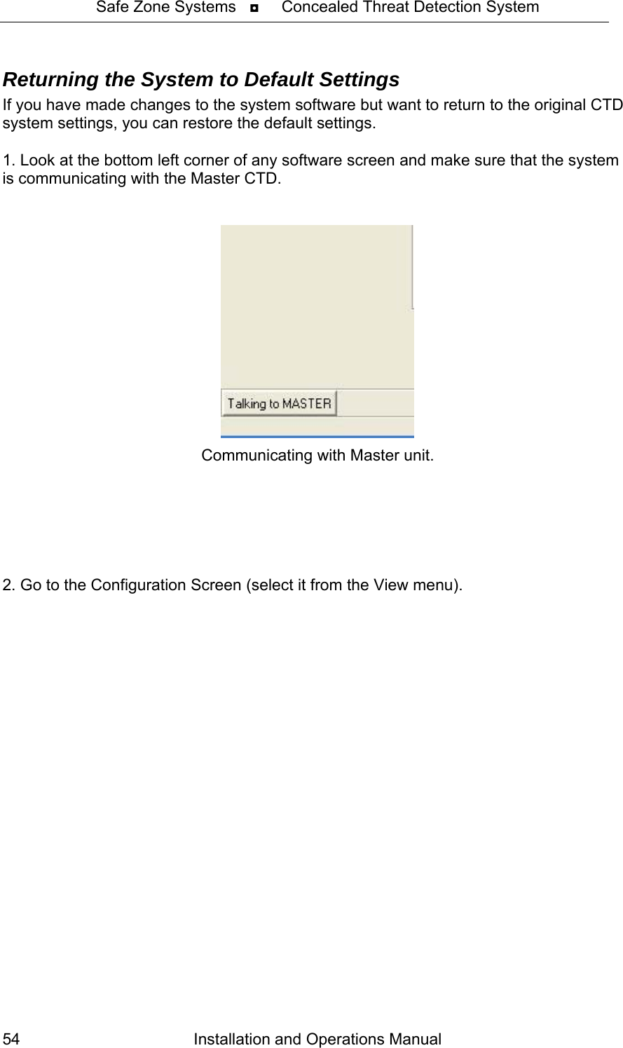
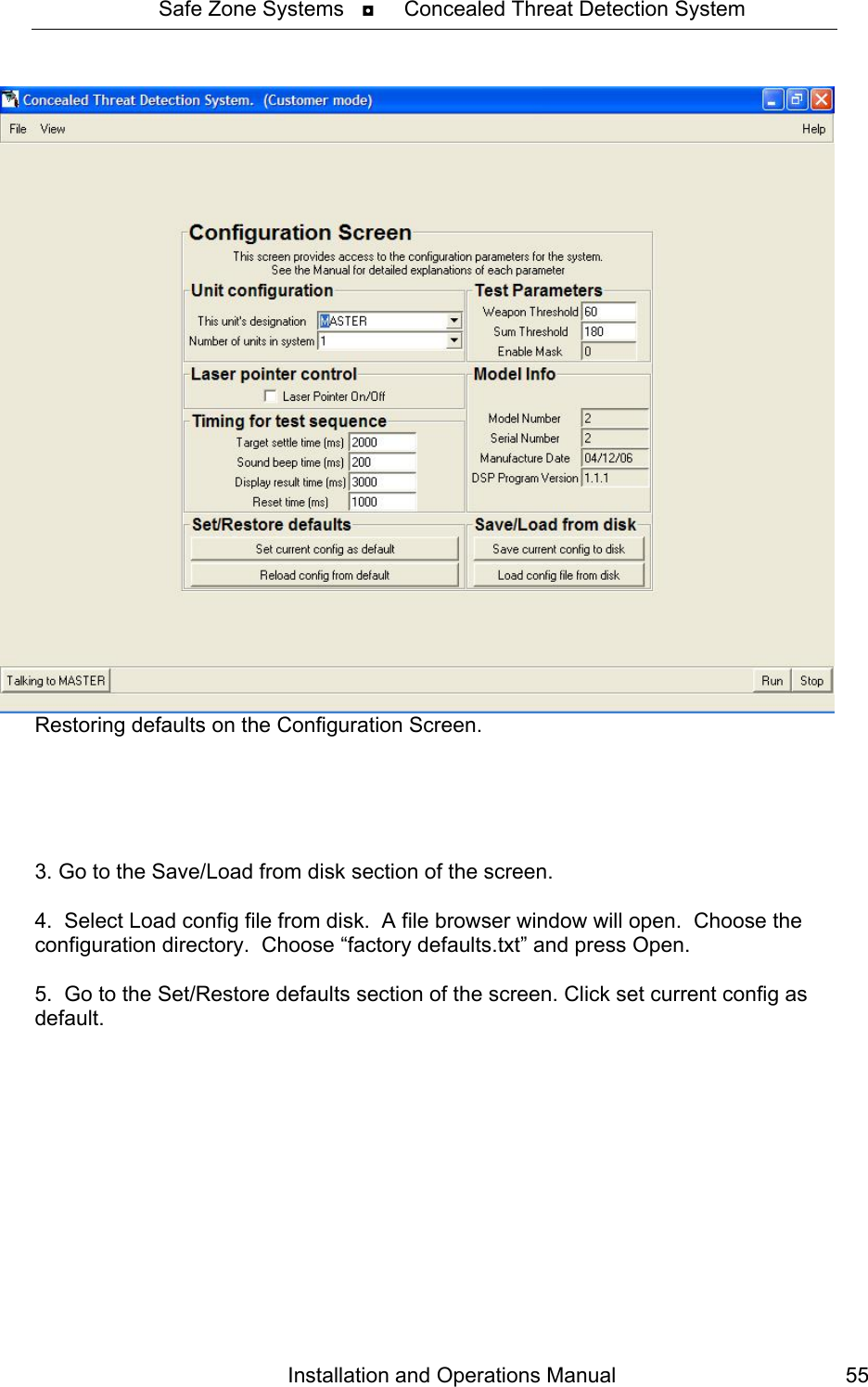
![Safe Zone Systems ◘ Concealed Threat Detection System Connection Instructions 1. Plug in cords to back of Master CTD unit • Plug in serial cable for portable computer. • Plug in keyboard cable. • Plug in two video cables. [Operator cable is the longer one (25 ft /7.62 meters). Prompter cable is the shorter one (6 ft. / 2 meters)]. The Operator Monitor will plug into the connection labeled Remote Output. The Prompter Monitor will plug into the connection labeled Prompt. • Plug in power supply cable and secure it with the Velcro strap so that it won’t pull out. • Display: This contact closure lets you perform a variety of functions, such as locking a door, or triggering an audible alarm. You can plug in the optional Display Box here. Back of Master CTD unit. 2. Plug in CTD unit(s) to electrical power receptacles 3. Connect CTD system components • Plug the power cords for the monitors into an electrical outlet. • Plug video cables from CTD unit into Auxiliary inputs on the monitors. • Plug keyboard cable coming from Master CTD unit into keyboard. • Plug serial cable into the portable computer (or use serial to USB adapter for computers without serial ports). Installation and Operations Manual 13](https://usermanual.wiki/Safe-Zone-Systems/CTD1000/User-Guide-824261-Page-16.png)