Safe Zone Systems CTD1000 CONCEALED WEAPON RADAR DETECTOR User Manual CTD manual notes
Safe Zone Systems, Inc. CONCEALED WEAPON RADAR DETECTOR CTD manual notes
MANUAL

Concealed Threat
Detector
Installation and Operations
Manual
CTD 1000 Series, version 01 A
Safe Zone Systems
7700 Ouray NW
Albuquerque, New Mexico 87120
USA

Safe Zone Systems ◘ Concealed Threat Detection System
Safe Zone Concealed Threat Detection System
Installation and Operations Manual
TABLE OF CONTENTS
INTRODUCTION............................................................................................................... 1
Check your environment—Site Survey.......................................................................... 1
Unpack parts from box(es) ............................................................................................ 1
Parts List.................................................................................................................... 2
Options List................................................................................................................ 2
User Supplied ............................................................................................................ 2
CTD Configurations ....................................................................................................... 2
Layout Diagrams ........................................................................................................... 3
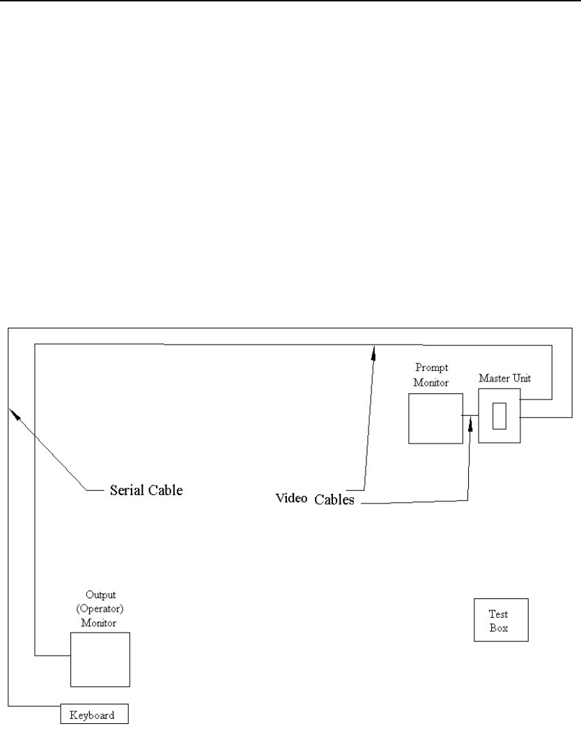
Layout for a CTD 1000 (single unit system)............................................................... 3
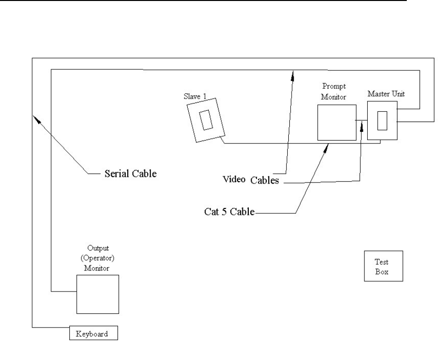
Layout for a CTD 1002 (two unit system) .................................................................. 4
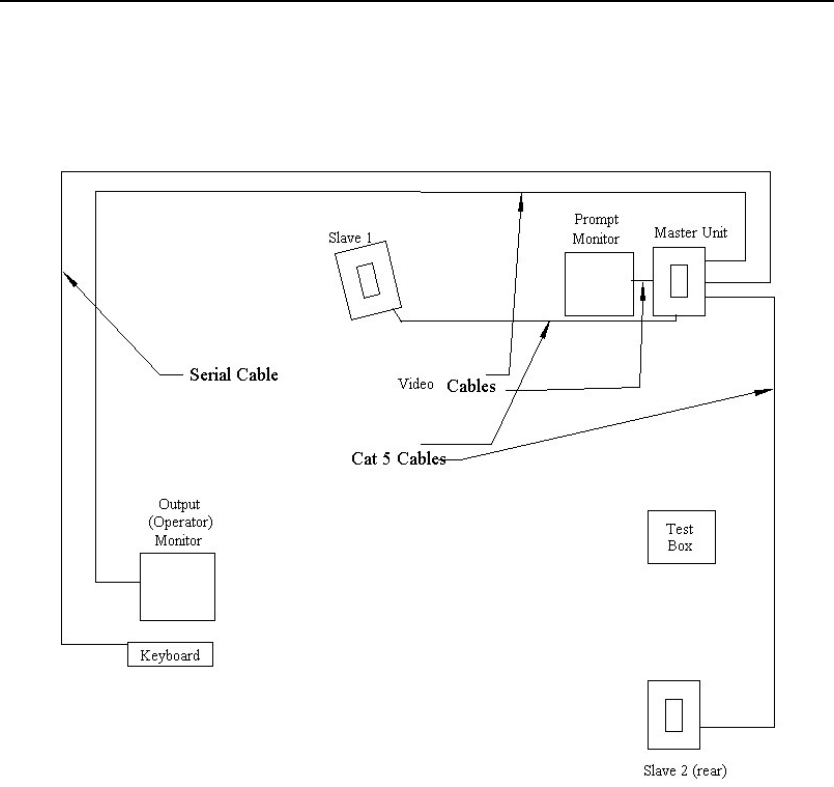
Layout for a CTD 1003 (three unit system)................................................................ 5
EVALUATION SETUP ...................................................................................................... 6
Get ready....................................................................................................................... 6
Dimension Guidelines.................................................................................................... 6
Position Components .................................................................................................... 7
CTD unit..................................................................................................................... 7
Prompter Monitor ....................................................................................................... 8
Operator Monitor and Keyboard ................................................................................ 8
Test Area ................................................................................................................... 8
Installing the Software ................................................................................................... 9
Computer System Requirements............................................................................... 9
Connections................................................................................................................. 10
Wiring Diagrams (CTD 1000, CTD 1002, CTD 1003).............................................. 10
Connection Instructions ........................................................................................... 13
Setting up Communications using the Software.......................................................... 15
Test Monitors...............................................................................................................18
Aiming the CTD ........................................................................................................... 19
Testing for Background Levels and Range ................................................................. 21
Testing for Background Levels ................................................................................ 22
Testing for Range—for CTD 1000, CTD1002, and CTD 1003 ................................ 24
Testing for Background Level and Range –only for CTD 1002 or CTD 1003.......... 28
Testing / Scanning Subjects ........................................................................................ 30
Test Results............................................................................................................. 35
PERMANENT INSTALLATION ....................................................................................... 37
Considerations............................................................................................................. 37
Weather ................................................................................................................... 37
Dust.......................................................................................................................... 37
Mounting .................................................................................................................. 37
Concealment............................................................................................................ 37
Operator’s Station....................................................................................................38
Security System Interface ........................................................................................ 38
Installation and Operations Manual i

Safe Zone Systems ◘ Concealed Threat Detection System
OPERATIONS................................................................................................................. 39
To Start Daily Operations ............................................................................................ 39
Keyboard Operations Menu......................................................................................... 39
To Run Tests ........................................................................................................... 40
Taking Readings...................................................................................................... 40
Results..................................................................................................................... 42
Response................................................................................................................. 43
Back Test (For 1000 or 1002)................................................................................. 43
OPTIMIZATION Field Adjustments ................................................................................. 44
Changing the Number of Units in a System ................................................................ 44
Changing the Designation of a Unit............................................................................. 46
Changing the Settle Time ............................................................................................ 48
Changing the Sound Beep Time ................................................................................. 50
Changing System Sensitivity (Thresholds).................................................................. 52
Returning the System to Default Settings.................................................................... 54
Changing the Operating Distance ............................................................................... 56
Changing the Neural Network ..................................................................................... 56
SOFTWARE REFERENCE............................................................................................. 57
Connection Screen ...................................................................................................... 57
Configuration Screen................................................................................................... 61
Plot Window................................................................................................................. 65
SERVICE AND MAINTENANCE..................................................................................... 66
Replacement Parts ...................................................................................................... 66
Technical Support........................................................................................................ 66
APPENDICES ................................................................................................................. 67
Appendix A Clutter..................................................................................................... 67
Appendix B The Testing Process ............................................................................... 68
Appendix C Radiation Safety...................................................................................... 70
Appendix D Technical Background on the CTD system............................................. 72
Glossary.......................................................................................................................... 73
Installation and Operations Manual ii

Safe Zone Systems ◘ Concealed Threat Detection System
INTRODUCTION
The Safe Zone Concealed Threat Detection System (CTD) is a fast, non-invasive threat
detection system designed to provide security against concealed bombs and weapons.
It scans people in real time, using low-power radar together with pattern recognition
software. With a detection rate in the high 90 percentiles, the Safe Zone CTD is a very
effective remote sensing system.
The CTD system works well with other security measures, and it transmits visible and
audible and electrical alerts. The electrical output can be used to perform actions such
as locking a door.
Small and lightweight, the system can be used in both permanent and portable
installations.
Check your environment—Site Survey
You, or someone in your organization, have probably already decided on a good location
to place the Safe Zone Concealed Threat Detection System (CTD). In order for the CTD
to operate well, that area should be cleared of any objects which might interfere with the
system’s radar signals.
The CTD transmits low-power radar signals and receives reflections of those signals.
Visible and non-visible clutter can contaminate the reflections. (For more information
about clutter, see Appendix A.)
Unpack parts from box(es)
Remove all of the parts from the boxes. Make sure that you have all the parts listed on
your packing list. See the Parts and Options Lists to see if there are any other parts or
options you might need.
Installation and Operations Manual 1

Safe Zone Systems ◘ Concealed Threat Detection System
Parts List
• CTD unit(s)—1 unit for CTD 1000, 2 units with CTD 1002, 3 units with CTD 1003
• CAT5 Ethernet cable to connect Master CTD unit to Slave unit(s)
• Power supply—1 for each CTD unit
• CTD Software CD
• Calibration and Spec Sheet—with your system’s specifications and calibration
information
Options List
• Operator Keyboard—for operator to control certain operations
• Keyboard adapter--DB9 to PS2 or DB9 to USB
• Serial USB cable—to connect Master CTD to your portable computer
• Keyboard Extension cable with PS-2 Connector —to connect keyboard to
CTD system
• Display box—has lights and sound beeper to give additional audible and visible
indications supplementing monitors
• Tripod adapter plate—to attach CTD to standard tripod
• Mounting Brackets--75mm or 100mm
• Antenna Shields
User Supplied
• Video monitors---(2) One Prompter video monitor and one Operator video
monitor
• Video cables—(2 composite) One for each of the video monitors
• Operator Keyboard—for operator to control certain operations
CTD Configurations
The Safe Zone CTD comes in one, two or three unit systems (CTD 1000, CTD 1002,
CTD 1003).
No matter which system you have, one unit is always designated as the Master.
Additional units are designated as Slave units.
• If you have a CTD-1000 system, the single unit will be the Master.
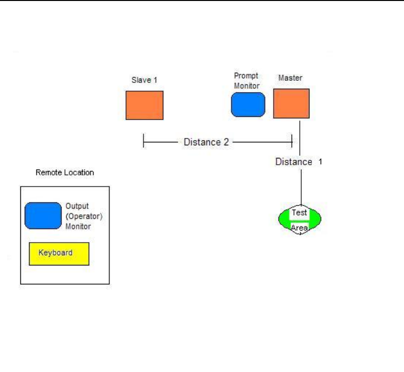
• If you have a CTD-1002 system, one unit will be the Master and the second unit
will be Slave 1.
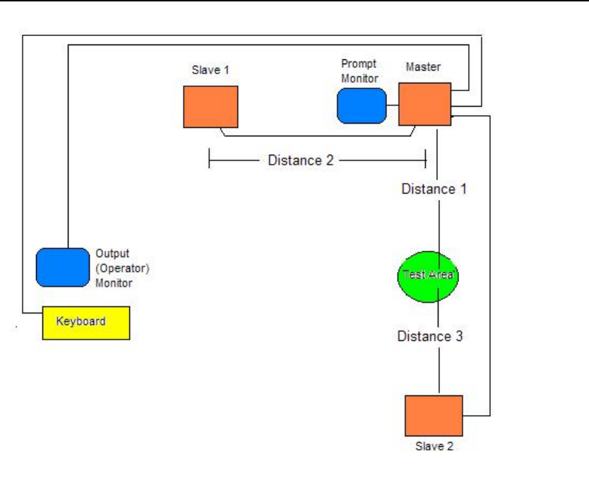
• If you have a CTD-1003 system, one unit will be the Master, one unit will be
Slave 1, and one unit will be Slave 2.
Installation and Operations Manual 2
Safe Zone Systems ◘ Concealed Threat Detection System
Layout Diagrams
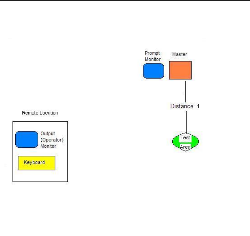
Layout for a CTD 1000 (single unit system)
Installation and Operations Manual 3
Safe Zone Systems ◘ Concealed Threat Detection System
Layout for a CTD 1002 (two unit system)
Installation and Operations Manual 4
Safe Zone Systems ◘ Concealed Threat Detection System
Layout for a CTD 1003 (three unit system)
Installation and Operations Manual 5

Safe Zone Systems ◘ Concealed Threat Detection System
EVALUATION SETUP
Before you install your CTD permanently, set up the components temporarily to test
operations and ensure the system is operating well in the environment you have
selected. Once you have everything adjusted to suit your needs, you can install all
components and wiring permanently.
Get ready
Before you begin the Evaluation Setup process, gather together the following items:
• Tape measure
• Portable Computer
• Masking tape
• Small Table(s): one table (or tripod) to set each unit on for Evaluation Setup.
• Plug adapter (if the plugs supplied on the power source will not fit your electrical
outlets.)
• Serial to USB adapter (only if your portable computer does not have serial port).
Dimension Guidelines
The Safe Zone CTD System is designed to operate with a distance of from 9 to 15 feet
(2.7 meters to 4.5 meters) between the units and the test subject. Look at the diagram
(and instructions) that match the system you have (CTD-1000, CTD-1002, or CTD-
1003).
Your CTD system has been optimized at the factory for the setup requested. Your CTD
unit(s) have been calibrated for specific distances. Look at the enclosed specifications
sheet and set up your system with the recommended distances between Master and
Slave units and the Test Area. Use the measurements on your specification sheet and
follow the diagram for your system.
If you want to change the distances between system components from what it was
calibrated for at the factory, please contact your sales representative.
Installation and Operations Manual 6
Safe Zone Systems ◘ Concealed Threat Detection System
Position Components
Following the diagram for your system and the measurements your system was
calibrated for, place the CTD unit(s), two Video monitors and keyboard as close to where
they will be in the permanent installation as possible. Mark off your planned Test Area
using tape. Make sure have enough clear space around all CTD components. Follow
the dimension diagram for your system.
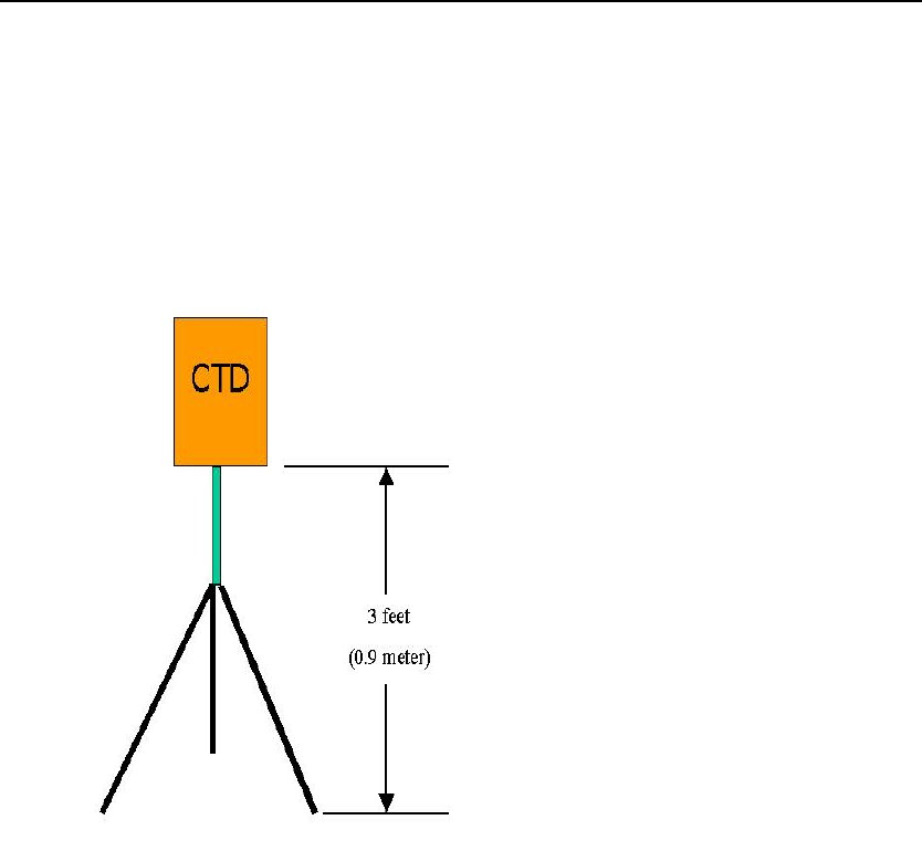
Set CTD unit height
CTD unit
The CTD unit(s) should be set so that each is pointed straight at the Test Area.
The unit should not be tilted up or down, but be level. Make sure the bottom of
the unit is about 3 feet (approx. 1 meter) from the ground or floor. The goal is for
the unit to be at about chest height of the average person.
Installation and Operations Manual 7

Safe Zone Systems ◘ Concealed Threat Detection System
Prompter Monitor
The Prompter Monitor will give instructions to the people you are testing. To
enable this, the monitor needs to be facing the Test Area. Place the
monitor just above or next to the Master CTD. You want your test subjects to
walk up to the Test Area, stand in the designated space, and face the
Prompter Monitor and Master CTD.
Operator Monitor and Keyboard
The Operator Monitor will display a video image of the test subject and test
results. The Operator Keyboard will let the operator start and stop the testing,
and perform other functions. For the Evaluation Setup phase, you can place
the Operator Monitor and Keyboard near each other, somewhere close by the
Master CTD unit. When you install the system permanently, you will probably
locate these out of sight of the Test Area, in a secure location.
Test Area
Designate an area approximately 2 feet x 2 feet (60cm x 60cm) where you will
want the people being tested to stand. You can mark this area with masking
tape, a car floor mat or another easily moved item during the Evaluation Setup
phase. When you install the system permanently, you can mark this area with
paint or other permanent material.
You might want to provide a container that test subjects can use to place their
personal belongings in while they are being tested. The container should be
placed about 5 feet (2 meters) off to the side of the test area so that it does not
show up in the beam of any unit.
Installation and Operations Manual 8

Safe Zone Systems ◘ Concealed Threat Detection System
Installing the Software
Computer System Requirements
• Portable computer running Microsoft Windows® 98, 2000 or XP
• 400Mhz processor minimum
• 128MB RAM
• Serial port (COM port) capable of 115200 baud or USB port
• USB to Serial adapter if your portable computer doesn’t have a serial port.
Install the software in the portable computer that you will use with the CTD system for
the Evaluation Setup.
To install the software, insert the CD. The installation wizard should run automatically.
If it does not, run the installation program from your CD player’s directory (the software
program file is called ctd.msi ). Once the software installation wizard has run, you
should have the CTD software listed on your Windows Start menu.
Installation and Operations Manual 9
Safe Zone Systems ◘ Concealed Threat Detection System
Connections
See the diagrams below and refer to the one for the CTD system you are installing (CTD
1000, CTD 1002, or CTD 1003). Instructions for making connections are on the pages
after these diagrams.
Wiring Diagrams (CTD 1000, CTD 1002, CTD 1003)
CTD 1000 wiring diagram
Installation and Operations Manual 10
Safe Zone Systems ◘ Concealed Threat Detection System
CTD 1002 wiring diagram
Installation and Operations Manual 11
Safe Zone Systems ◘ Concealed Threat Detection System
CTD 1003 wiring diagram
Installation and Operations Manual 12
Safe Zone Systems ◘ Concealed Threat Detection System
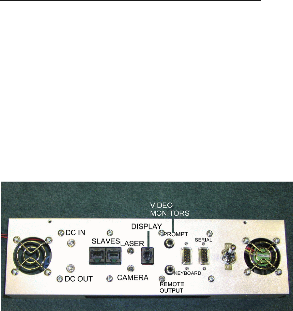
Connection Instructions
1. Plug in cords to back of Master CTD unit
• Plug in serial cable for portable computer.
• Plug in keyboard cable.
• Plug in two video cables. [Operator cable is the longer one (25 ft /7.62 meters).
Prompter cable is the shorter one (6 ft. / 2 meters)]. The Operator Monitor will
plug into the connection labeled Remote Output. The Prompter Monitor will plug
into the connection labeled Prompt.
• Plug in power supply cable and secure it with the Velcro strap so that it won’t pull
out.
• Display: This contact closure lets you perform a variety of functions, such as
locking a door, or triggering an audible alarm. You can plug in the optional
Display Box here.
Back of Master CTD unit.
2. Plug in CTD unit(s) to electrical power receptacles
3. Connect CTD system components
• Plug the power cords for the monitors into an electrical outlet.
• Plug video cables from CTD unit into Auxiliary inputs on the monitors.
• Plug keyboard cable coming from Master CTD unit into keyboard.
• Plug serial cable into the portable computer (or use serial to USB adapter for
computers without serial ports).
Installation and Operations Manual 13

Safe Zone Systems ◘ Concealed Threat Detection System
4. For two or three unit system (CTD1002, CTD 1003)
If you have a CTD 1002 or 1003 system, you now need to connect your Slave unit(s).
If you have a CTD 1000 system, you can go on to step 5.
• Plug in the power supply from the unit to an electrical outlet for each Slave unit.
• Plug a network cable into the network plug on each Slave unit.
• Plug the other end of the Network cable into either of the Master unit’s RJ-45
jacks.
5. For all systems
• Turn on the Master and Slave CTD units.
• Turn on the two monitors.
Connecting your computer to the CTD system
If you have not done so already, connect your portable computer to the Master CTD
Installation and Operations Manual 14
Safe Zone Systems ◘ Concealed Threat Detection System
Setting up Communications using the Software
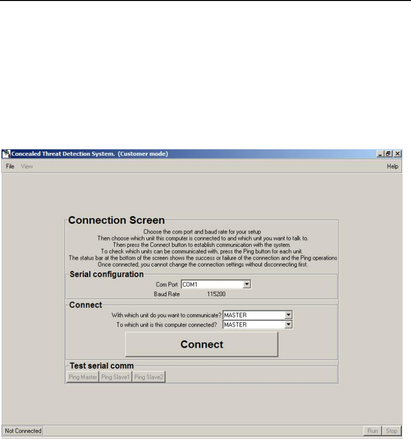
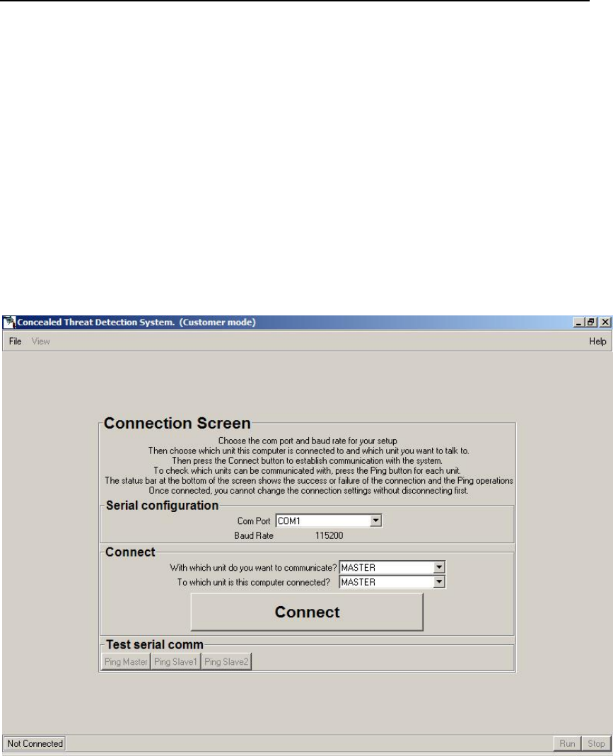
Start the CTD program. It will open to the Connection Screen.
You will use the Connection Screen to set up communications with your CTD system.
Once the CTD system is successfully connected, you will be able to access other CTD
software screens using the View button. Until the CTD is connected, the View button is
disabled.
Setting up communications using the Connection Screen.
1. Connection Screen--Serial Configuration
COM Port
Choose the appropriate COM port for your computer’s hardware configuration. If you
don’t know which port to select, just try one. You will be able to check if you have
selected the correct COM port when you test communications in the next step of the
process. If you have not selected the correct COM port, you will get an error message
and be able to try another COM port.
Baud Rate
The Baud Rate is set to 115200. This is the rate the CTD system requires. No
adjustments are necessary or possible.
Installation and Operations Manual 15
Safe Zone Systems ◘ Concealed Threat Detection System
2. Connection Screen--Connections
With which unit do you want to communicate?
Choose Master
For this part of the Evaluation Setup, we will be communicating with the Master CTD unit
whether you have a CTD1000, 1002, or 1003.
To which unit is this computer connected?
Choose Master
Your portable computer should be connected to the Master CTD, therefore make sure
Master is selected.
3. Connection Screen—Connect
• Click the Connect button.
This will begin communications between the computer and the CTD system.
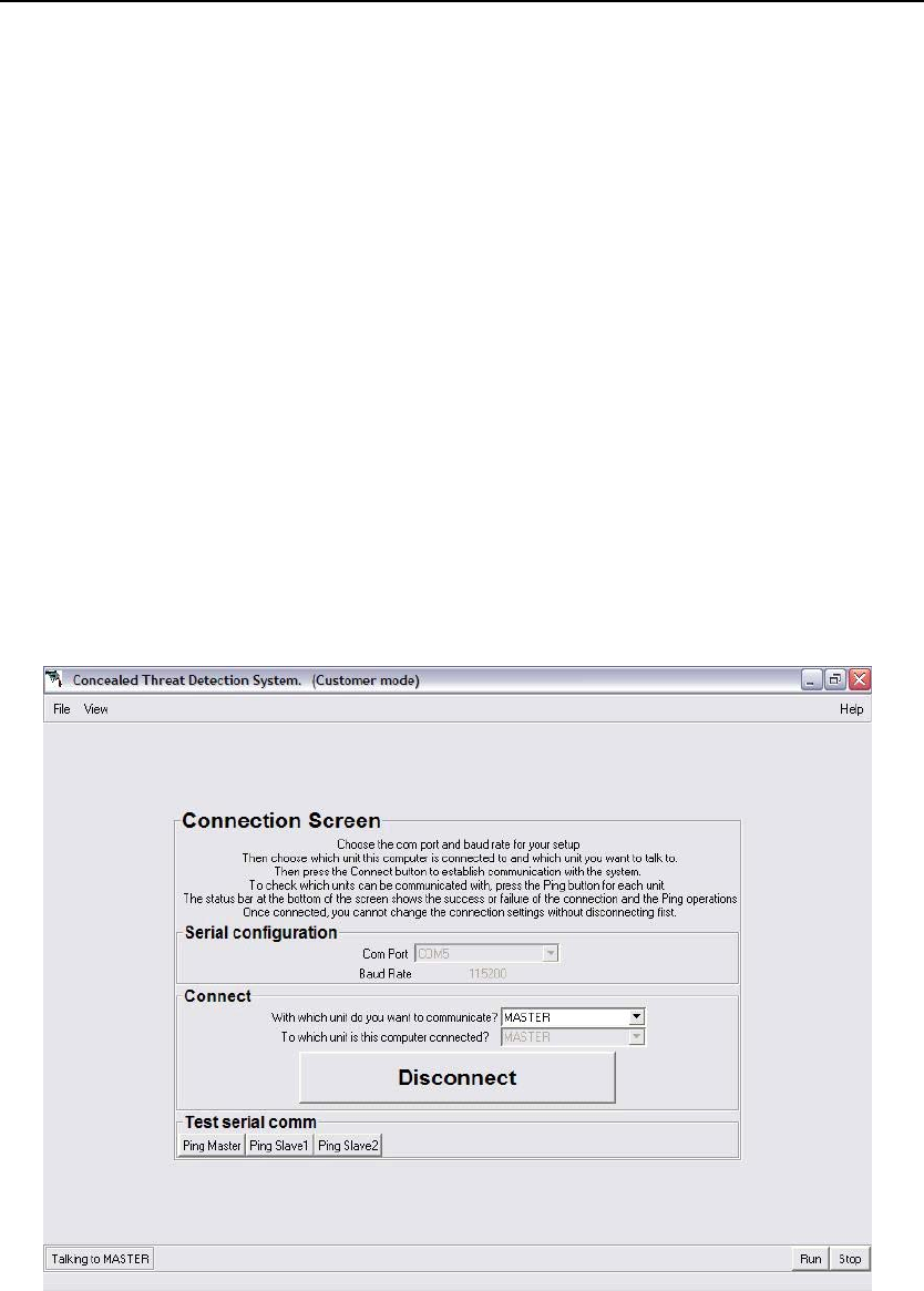
• The button should now say Disconnect.
• At the bottom left of the screen it should flash Connected and then say Talking to
Master.
• The View Menu at the top left of the screen should be enabled.
Connecting to the Master unit using the Connection Screen.
Note: If you are Connected, the Serial configuration and Connections items will be disabled. If
you want to change them later, you have to Disconnect by pushing the Disconnect button.
Installation and Operations Manual 16
Safe Zone Systems ◘ Concealed Threat Detection System
If you have a CTD 1000 (one CTD unit) you have completed the connection process.
You can go on to the Testing Background Levels and Range section.
If you are not getting a connection, you might see an error message like this: COM
port setup is good, but an attempt to Ping master unit failed. Check the power and cable
to the unit and try the Ping button.
Make sure your computer is properly connected and/or try another COM port.
If you have a CTD 1002 or CTD 1003, use Test serial comm. buttons to test
communication with your Slave 1 and/ or Slave 2 CTD units.
For CTD 1002
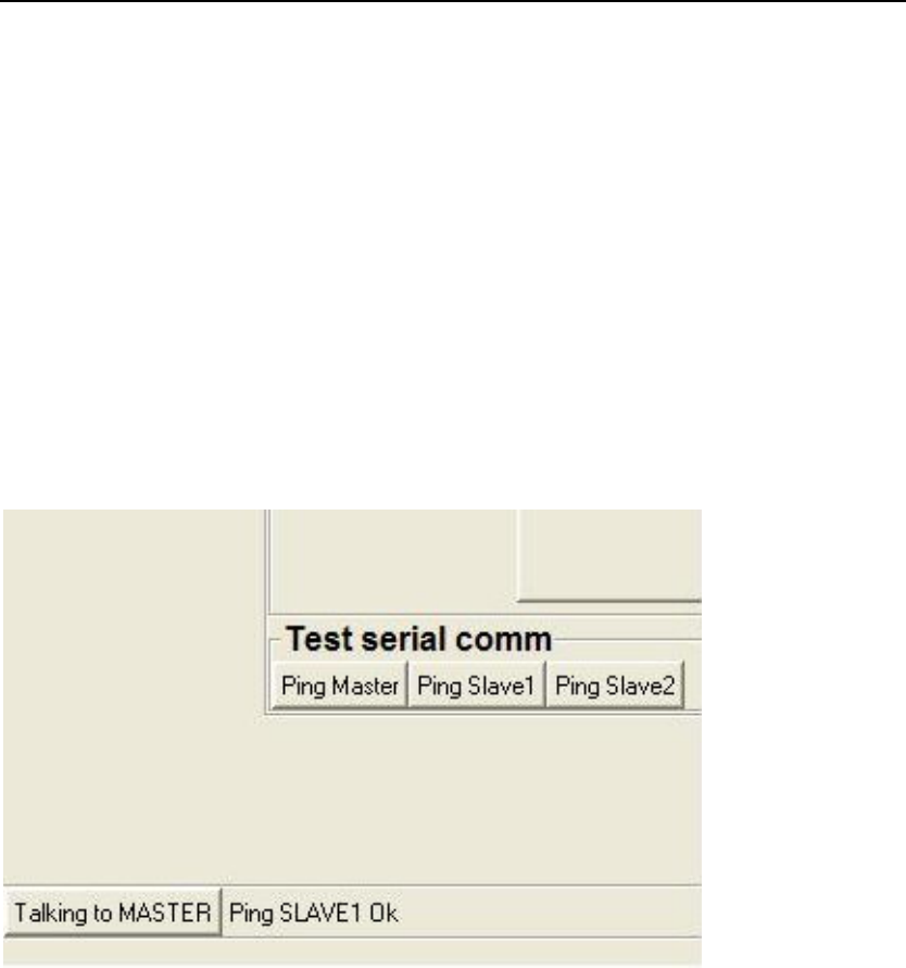
Click Ping Slave 1 at the bottom of the Connection Screen in the Test serial comm. area.
If it is connected properly, you will see the message Ping Slave 1 OK at the bottom of
the screen.
Testing communications using Ping Slave 1 on the Connection Screen.
For CTD 1003
Click Ping Slave 1 near the bottom of the Connection Screen in the Test serial comm.
area.
If it is connected properly, you will see the message Ping Slave 1 OK at the bottom of
the screen.
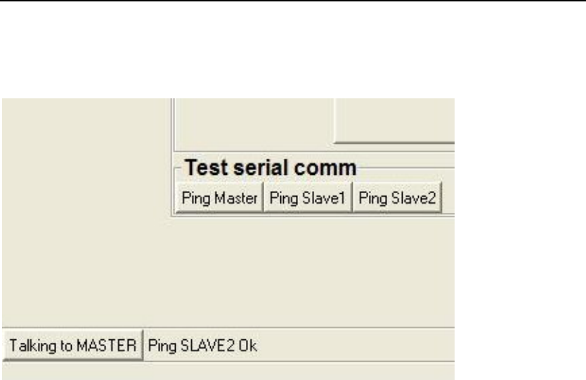
Click Ping Slave 2 at the bottom of the Connection Screen in the Test serial comm. area.
Installation and Operations Manual 17
Safe Zone Systems ◘ Concealed Threat Detection System
If it is connected properly, you will see the message Ping Slave 2 OK at the bottom of
the screen.
Testing communications using Ping Slave 2 on the Connection Screen.
If you get a message saying Ping Failed
Check to make sure all cables are connected to the CTD and other
components properly. Make sure that all CTD units are turned on.
Once you have successfully communicated with your Master and any Slave CTD
units, you are ready to continue with the Evaluation Setup process and then test for
background levels and range.
Test Monitors
Once all components are plugged in and connected to each other, the Prompter Monitor
will say Safe Zone Threat Detector.
The Operator Monitor will show you a video picture of what the video camera inside the
Master unit is seeing. It will have the same message, Safe Zone Threat Detector, near
the top of the screen. The text Press Run to Begin will be superimposed on the picture.
Your video picture should be showing you the area where you want the person being
tested to stand (Test Area).
Installation and Operations Manual 18
Safe Zone Systems ◘ Concealed Threat Detection System
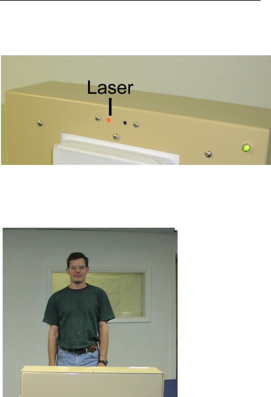
Aiming the CTD
To make sure that each CTD unit is aligned properly and aimed at where a person/test
subject will be standing, use the red laser that is built in to each unit.
Using the laser to aim the CTD at test subjects.
Press the laser button on the connector panel at the bottom of the CTD unit to toggle the
laser on and off. Adjust the CTD unit so the red dot is aimed at the middle of a person’s
stomach when they stand in the spot you’ve selected as the Test Area.
Person with laser aimed at their stomach.
Installation and Operations Manual 19

Safe Zone Systems ◘ Concealed Threat Detection System
Test the alignment of each CTD in your system by standing in the Test Area or having
another person stand there. Adjust each of your CTD units (Master and Slave(s) the
same way, using their lasers. Turn off the laser(s) when you are done by pressing the
laser button on each CTD unit.
SAFTETY NOTE: Although it is not a strong laser (only 1 milliwatt) you should turn the
laser off when you are done with testing so people can avoid inadvertent eye exposure.
Installation and Operations Manual 20
Safe Zone Systems ◘ Concealed Threat Detection System
Testing for Background Levels and Range
Go to the View menu at the top of the Connection Screen. Choose Plot to open the Plot
Window.
Plot window
Plot window—Plot
In the Plot window you can view the signal from your CTD system. This will verify that
the Test Area is the correct distance from the CTD(s). It will also help you determine
that there isn’t too much visible or non-visible clutter in the test area that could prevent
your CTD from providing accurate readings. (For more about clutter, see Appendix A.)
The Plot window shows a graph of the radar reflection from objects in the Test Area.
The horizontal axis is time which is related to distance.
NOTE: This test should be run first with Master selected as the unit you want to
communicate with. If you have changed the setting, return it to Master on the
Connection Screen before running this test.
Installation and Operations Manual 21
Safe Zone Systems ◘ Concealed Threat Detection System
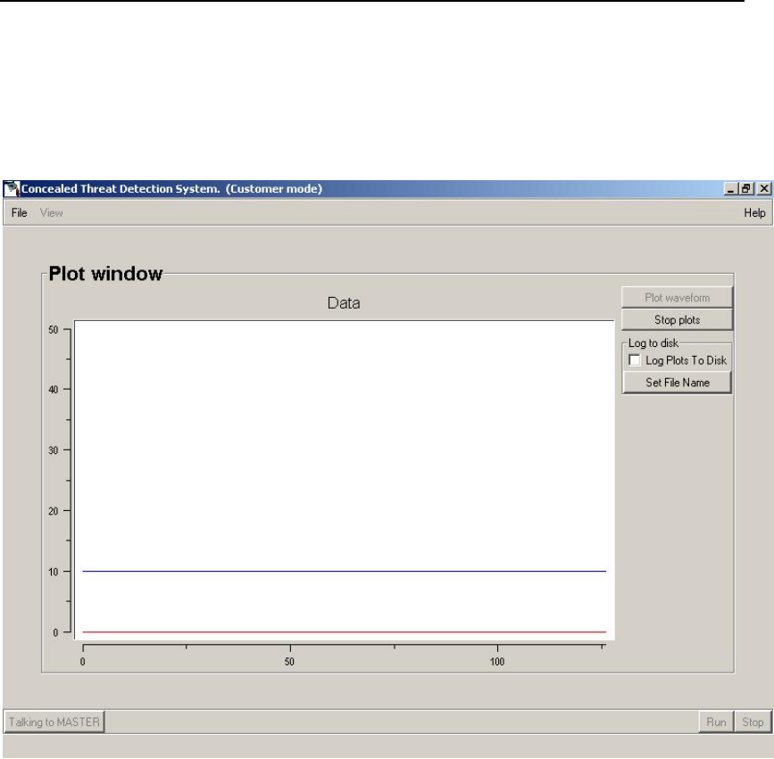
Testing for Background Levels
1. Click the Plot button.
• You should see a waveform displayed in the Plot window. It will show you the
radar reflection from objects in the test area.
• If there is no visible or non-visible clutter interfering and creating “noise”, the plot
should be two flat lines. Small ripples (less than 5 dB) are acceptable.
Plot window showing a “good” flat plot.
Installation and Operations Manual 22
Safe Zone Systems ◘ Concealed Threat Detection System
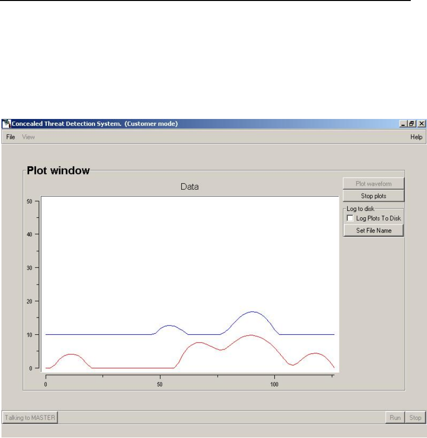
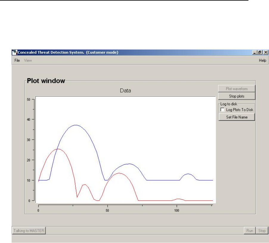
• If your waveform has responses greater than 5 dB, look for any objects in the test
area that might be causing this and remove them. These undesired responses
can interfere with the desired signal. Interference can be caused by things like
chairs, flowerpots, trash cans, or even a cable or electrical wire crossing the test
area. You can also try moving the CTD(s) slightly, if possible.
Plot window showing a “bad” wavy plot with possible interference.
• If the cause of the interference is not apparent, it could be non-visible clutter.
See Appendix A for more information about clutter, or contact your sales
representative for help.
Installation and Operations Manual 23
Safe Zone Systems ◘ Concealed Threat Detection System
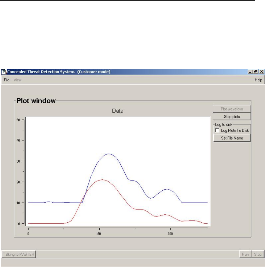
Testing for Range—for CTD 1000, CTD1002, and CTD 1003
1. Place an object such as a chair in the Test Area. If the object is at the correct
distance from the CTD you should observe a peak in the signal roughly in the center of
the graph. The object represents the Test Subject during this test.
“Good” plot with peak roughly in center.
Installation and Operations Manual 24
Safe Zone Systems ◘ Concealed Threat Detection System
• If the peak is to the left of center, the unit is too close to the Test Subject.
Plot with peak to left of center.
Installation and Operations Manual 25
Safe Zone Systems ◘ Concealed Threat Detection System
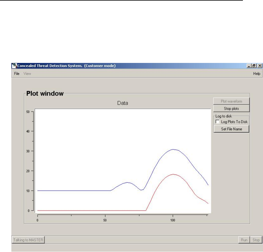
If the peak is to the right of center, the CTD unit is too far from the Test Subject.
Plot with peak to right of center.
• Adjust the chair or other object you are using as the Test Subject for this test until
the peak is in the center of the graph.
Installation and Operations Manual 26
Safe Zone Systems ◘ Concealed Threat Detection System
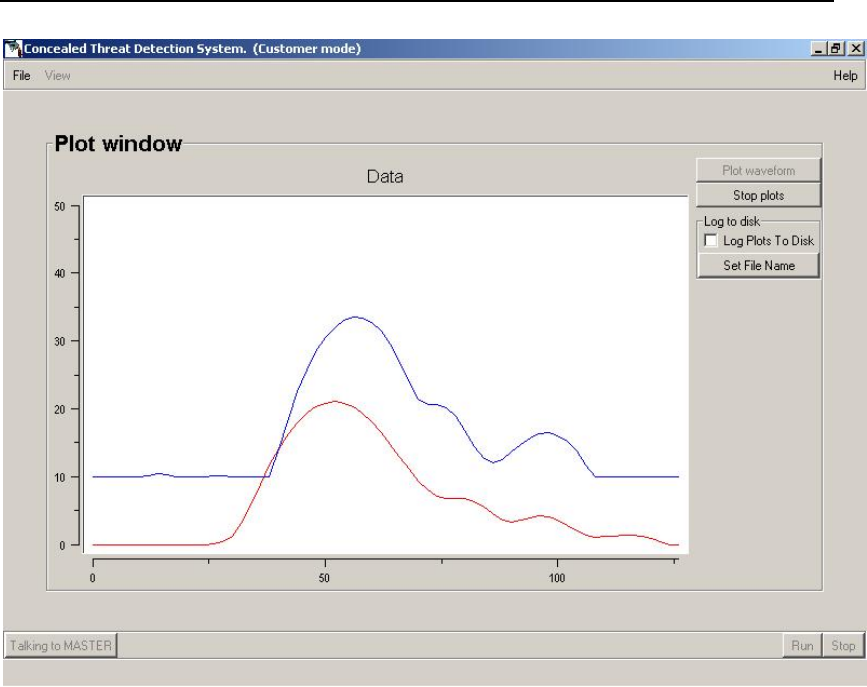
Plot showing “good” peak in center of graph.
2. Push the Stop button to stop the plotting operation. You must stop the plot before you
can continue on to other software screens and features.
• If you have a CTD 1000 (only one CTD unit), you are done with testing for
background levels and range.
• If you have a CTD 1002 or CTD 1003, go on to the next section to test the
background levels and range of your Slave unit(s).
• If you have moved your CTD(s) or Test Area while testing for Range, make
sure that the Master and Slave unit(s) are still the correct distances from each
other. Refer to the calibration and spec sheet that came in the box with your
system to see the correct distances and adjust components as necessary.
Installation and Operations Manual 27
Safe Zone Systems ◘ Concealed Threat Detection System
Testing for Background Level and Range –only for CTD 1002 or CTD
1003
After testing for background level and range while communicating with the Master CTD,
you need to test the Slave 1 and/or Slave 2 CTDs.
1. Push the Stop Button to stop the previous Plotting operation (if you have not
already done so).
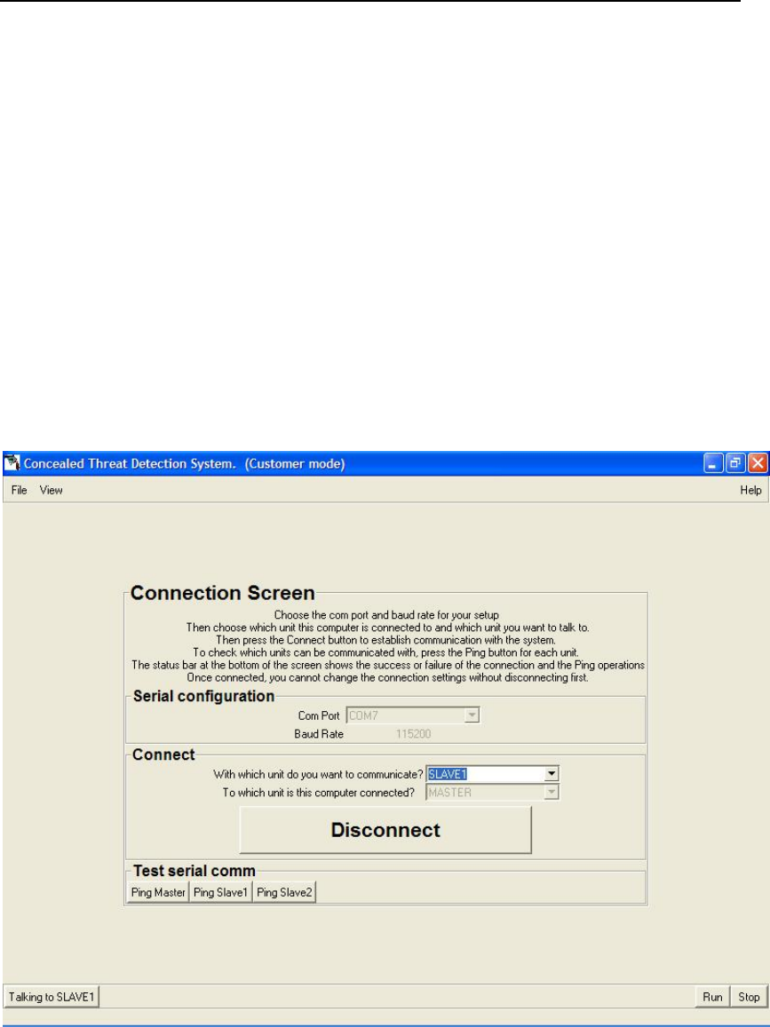
2. Go to View at the top left of the window and select Connection Screen.
3. In the Connections area of the Connection Screen go to “With which unit do you
want to communicate?” Select Slave 1.
4. Once you have selected Slave 1 the message in the bottom left of the screen
should say Talking to Slave 1.
Connection Screen selecting Slave 1.
Installation and Operations Manual 28

Safe Zone Systems ◘ Concealed Threat Detection System
View the plot
5. Go to View at the top left of the window and select the Plot Window.
6. Push the Plot button to see the waveform in the graph.
7. Follow all the steps in the Testing for Background Levels and Testing for Range
sections as you did for the Master CTD unit. The one exception is that you
should move the CTD units instead of the Test Area to center the plots on the
screen.
When you are finished with testing, push the Stop button to stop the plotting process.
You must stop the plot before you can continue on to other parts of the software.
• If you have a CTD 1002 (two CTD units), you are done with testing for
background levels and range.
• If you have a CTD 1003 (three CTD units), you now need to test the
background levels and range for your Slave 2 unit. Repeat the process you
followed for Slave 1, selecting Slave 2 as the unit you want to communicate with
on the Connection Screen.
• If you have moved your CTD(s) or Test Area while testing for Range, make
sure that the Master and Slave unit(s) are still the correct distances from each
other. Refer to the calibration and spec sheet that came in the box with your
system to see the correct distances and adjust components as necessary.
Installation and Operations Manual 29
Safe Zone Systems ◘ Concealed Threat Detection System
Testing / Scanning Subjects
Practice testing some people (sample test subjects) before you install the CTD system
permanently.
1. Go to the Connection Screen by opening the CTD software or by selecting
Connection from the View menu if you already have the software running. Make sure
that you are communicating with the Master CTD.
2. Connection Screen--Connections
With which unit do you want to communicate? Choose Master
Getting ready to test subjects using the Connection Screen.
Installation and Operations Manual 30
Safe Zone Systems ◘ Concealed Threat Detection System
3. Click the Run button at the bottom right of the Connections Screen.
If the button is inactive, it means you are not properly connected to the CTD
system. See the previous steps in this manual for more information.
4. After you push Run, the CTD system is ready to run tests.
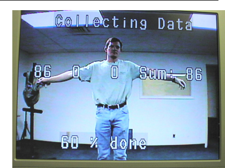
Your computer will be switched to the Status Screen. You will see the same status and
test result information on your portable computer as is shown on the Operator Monitor.
However, your computer will not display the video picture.
Status screen in the process of collecting data during a test.
While running a test, all other screens are disabled.
To stop the testing process, press the Stop button.
Installation and Operations Manual 31
Safe Zone Systems ◘ Concealed Threat Detection System
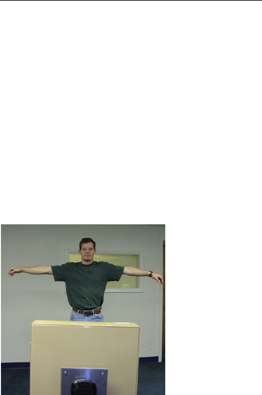
Have a person stand in the Test Area.
• The CTD system will automatically detect when a subject enters the Test Area
and begin the testing process.
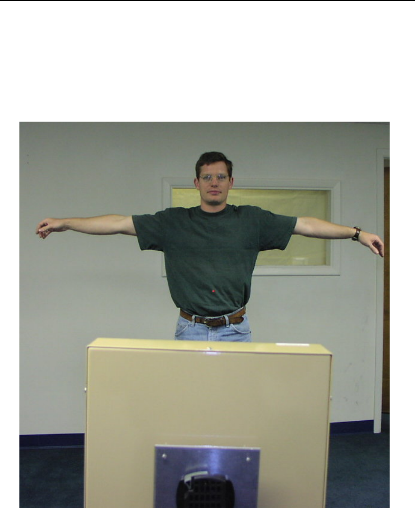
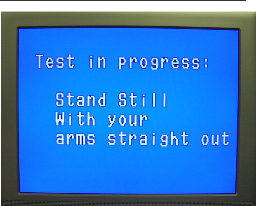
• The Prompter Monitor will give the test subject instructions. The instructions will
tell the person to stand still and to hold their arms out straight from their sides.
A person (Test Subject) properly positioned for threat testing.
Installation and Operations Manual 32
Safe Zone Systems ◘ Concealed Threat Detection System
Installation and Operations Manual 33
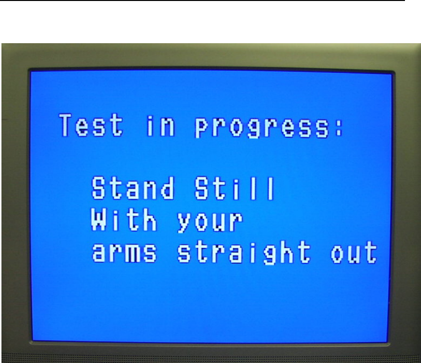
Prompter Monitor giving instructions to Test Subject.
• A “settle” time before the scan starts allows the test subject time to get in
position.
• The actual testing process takes from about four to six seconds. It is important
that the test subject stand still during this time.
Safe Zone Systems ◘ Concealed Threat Detection System
Test progress on Operator Monitor showing percent done.
• The Operator Monitor will show the test progress using numbers showing the
percent of the test completed.
• When the test is done, the results will appear instead of the percent of
completion (% done).
Installation and Operations Manual 34
Safe Zone Systems ◘ Concealed Threat Detection System
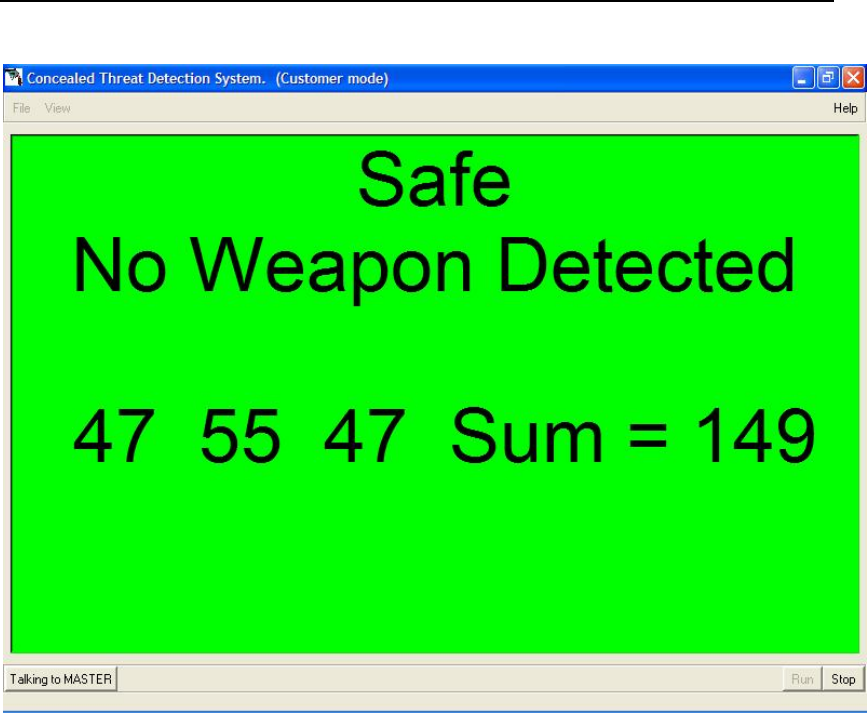
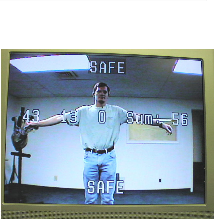
Test results for three readings.
Test Results
The results of the test will appear on the Operator Monitor and your portable computer
(when it is connected to the CTD). Results take the place of the percent done
information.
Results are in two parts. The first part is the scores. Individual scores from the two or
three scans run as part of each test will be shown along with the total score (Sum).
The second part of the results is the decision determined by the CTD software’s neural
network based on the scores and the thresholds selected for your installation. The
decision will be one of three possibilities: Safe, Caution or Threat. A Safe decision will
be shown on a green computer screen. A Threat Decision will be shown on a red
screen. An inconclusive, or Caution decision will be shown on a yellow screen.
Installation and Operations Manual 35
Safe Zone Systems ◘ Concealed Threat Detection System
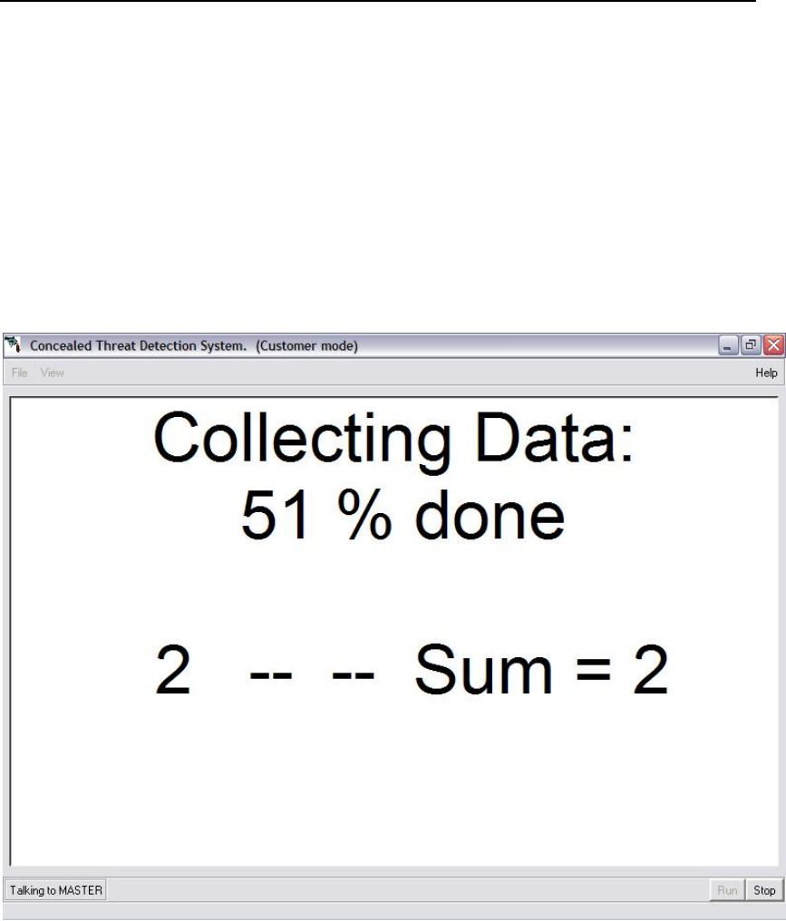
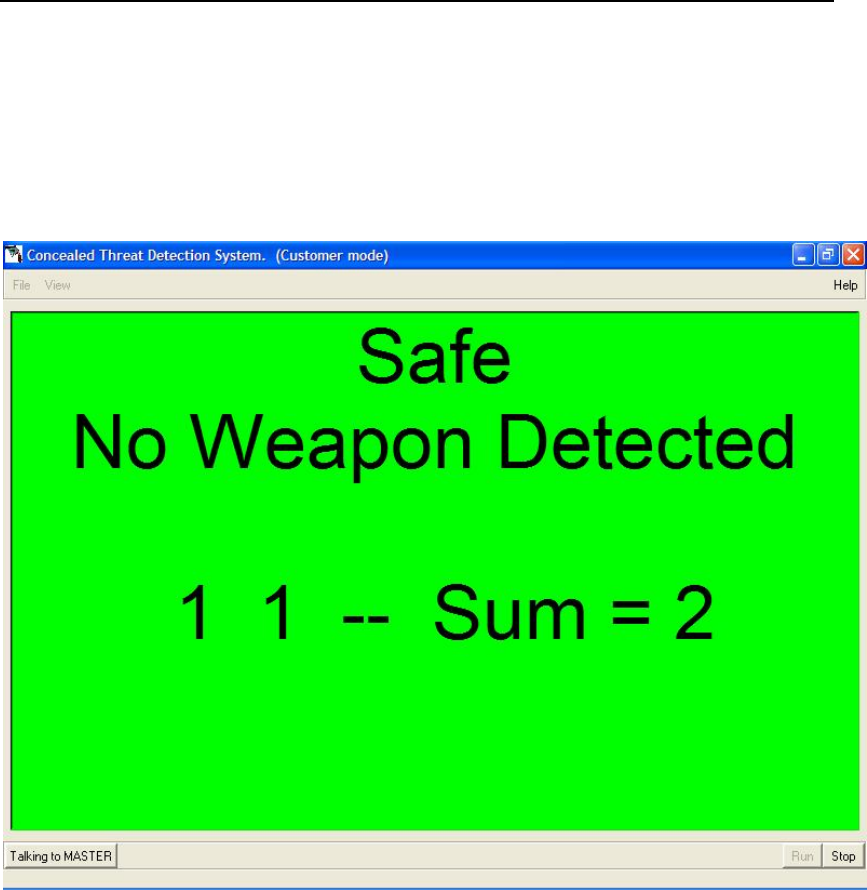
Generally the system takes three readings on each test subject. If a definite conclusion
is reached after the first two readings, the third reading is not taken. (If only two
readings are taken, the percent done shown on the Operator Monitor will not reach
100% but will finish at 66%.
Test results for two readings.
You need to decide what action(s) you would like the Operator to take at your installation
for results that are listed as Safe, Caution or Threat. You can also adjust your
thresholds to change what scores return each of these results.
Thresholds can be changed by using the Test Parameters section of the Basic
Configuration screen in the CTD software. For more information about Thresholds and
changing them, see Changing System Sensitivity (Thresholds) in the Optimization
section of this manual and Appendix B.
Installation and Operations Manual 36

Safe Zone Systems ◘ Concealed Threat Detection System
PERMANENT INSTALLATION
Once you’ve completed all the steps of the Evaluation Setup, you are ready to install the
CTD system permanently. You can mount equipment securely and run wiring so that it
is concealed.
Considerations
Weather
Use a non-conductive hood (plastic, wood, fiberglass or other material—not metal) over
the CTD unit(s) to protect them from excessive moisture.
The system has been tested to operate over a wide range of temperatures—from
-20oC to +50oC (-4oF to +131o F). If you’re mounting the CTD unit(s) on a wall that is
exposed to the sun, you must consider the sun load to prevent the outer box of the CTD
from exceeding the upper limits of the temperature range.
Dust
Gaskets or grommets can be used to keep excessive dust and/or sand from coming into
the openings where the wires exit the CTD box.
Mounting
You can use standard mounting brackets to mount the CTD unit(s) using either the
75mm or 100mm hole patterns. Obtain mounting brackets from Safe Zone or use
industry standard brackets you purchase locally.
Wires can be run out of the back or bottom of the CTD box. Simply move the back plate
of the box depending on which way you want the wires to run for your installation.
Concealment
If the CTD unit is to be concealed, it can be covered with a cloth, such as a tapestry.
The cloth should not have any metal threads or other conductive components in it. A
plastic covering can be used if it is less than .03” inches (0.75mm) thick.
NOTE: Once the CTD is covered, the radar will still function but the video camera and
laser will not be usable.
Installation and Operations Manual 37

Safe Zone Systems ◘ Concealed Threat Detection System
Operator’s Station
The operator’s station should be in a safe location, with some barrier between the
operator and the people being tested.
Security System Interface
The CTD can be linked to other sensors in a security system. Consult your sales
representative for interface information.
Installation and Operations Manual 38

Safe Zone Systems ◘ Concealed Threat Detection System
OPERATIONS
The CTD operator(s) should be trained how to turn the CTD system on and off, how to
respond to potential Threat readings, and how to use the Operator keyboard and its
commands to control certain operations.
Once the CTD system is permanently installed, daily operations can be controlled via the
Operator keyboard.
Optimization, diagnostics, or system changes can be performed using your portable
computer and the CTD software.
To Start Daily Operations
The operator needs to turn on the CTD unit(s) and the two video monitors (Operator and
Prompter).
Once all components are powered up, the operator has to Press R for Run on the
Operator keyboard.
Keyboard Operations Menu
The operator can press M on the keyboard to see the complete menu of keyboard
commands.
M for Menu
R for Run (defaults to a front reading)
S for Stop
L for Laser (toggles laser on and off)
F for Front reading (to revert to front after taking a back reading)
B for Back (for taking back readings with 1000 and 1002)
Installation and Operations Manual 39
Safe Zone Systems ◘ Concealed Threat Detection System
To Run Tests
The operator needs to make sure the system is running. If it is not yet running, the
operator should press R on the Operator keyboard to begin the process.
After Run is active, the CTD system is ready to run tests.
The operator can see the status and test result information on the Operator Monitor.
Container for personal belongings
Tell the subject to place any items they are carrying such as packages, briefcase etc. in
the container you have provided for this purpose. They can collect their belongings after
the test.
Tell the subject to stand in the Test Area.
The Prompter Monitor will also give the subject instructions, but verbal instructions can
supplement the screen instructions, if desired.
Taking Readings
The CTD system will automatically detect when a subject enters the Test Area and begin
the testing process, making its readings.
The Prompter Monitor will give the test subject instructions. The instructions will tell the
test subject to stand still and to hold their arms out straight from their sides.
A person properly positioned for threat testing.
Installation and Operations Manual 40
Safe Zone Systems ◘ Concealed Threat Detection System
Prompter Monitor with instructions for test subject.
A “settle” time before the scan starts allows the test subject time to get in position.
The actual testing process takes from about four to six seconds. It is important that the
test subject stand still during this time.
The Prompter Monitor will then show the test progress with numbers showing the
percent of the test completed as the test runs.
Installation and Operations Manual 41
Safe Zone Systems ◘ Concealed Threat Detection System
Results
When the test is done, the results will appear instead of the percent done (% done) on
the Operator Monitor.
Test results on Operator Monitor for three readings.
Results are in two parts. The first part is the scores. Individual scores from the two or
three scans run as part of each test will be shown along with the total score (Sum).
The second part of the results is the decision determined by the CTD software’s neural
network based on the scores and the thresholds selected for your installation. The
decision will be one of three possibilities: Safe, Caution or Threat.
Generally the system takes three readings on each test subject. If a definite conclusion
is reached after the first two readings, the third reading is not taken. (If only two
readings are taken, the percent completed shown on the Monitors will not reach 100%
but will finish at 66%.)
Installation and Operations Manual 42

Safe Zone Systems ◘ Concealed Threat Detection System
Response
If a Caution or Threat indication is seen, the operator will need to refer to their own
internal security procedures. It is your responsibility to train your operator(s) on what
action or actions you want them to take in various situations. You can also adjust your
thresholds to change what scores return each of these results.
Thresholds can be changed by using the Test Parameters section of the Basic
Configuration screen in the CTD software. For more information about Thresholds and
changing them, see the Optimization section of this manual and Appendix B.
Back Test (For 1000 or 1002)
Once the Front test is complete, the operator can tell the test subject to turn around.
Once the person is in place and has turned around, then the operator hits B for back on
the Operator keyboard. The CTD system will then take the back readings and results
will be displayed.
The operator then tells the test subject the test is done. With their back to the Prompter
Monitor, it will not be possible to give the test subject written commands on screen.
The CTD system will know when it is done with the back reading and will automatically
reset itself to do the front reading for the next test subject.
Installation and Operations Manual 43
Safe Zone Systems ◘ Concealed Threat Detection System
OPTIMIZATION Field Adjustments
Changing the Number of Units in a System
You can add or delete units from your CTD system.
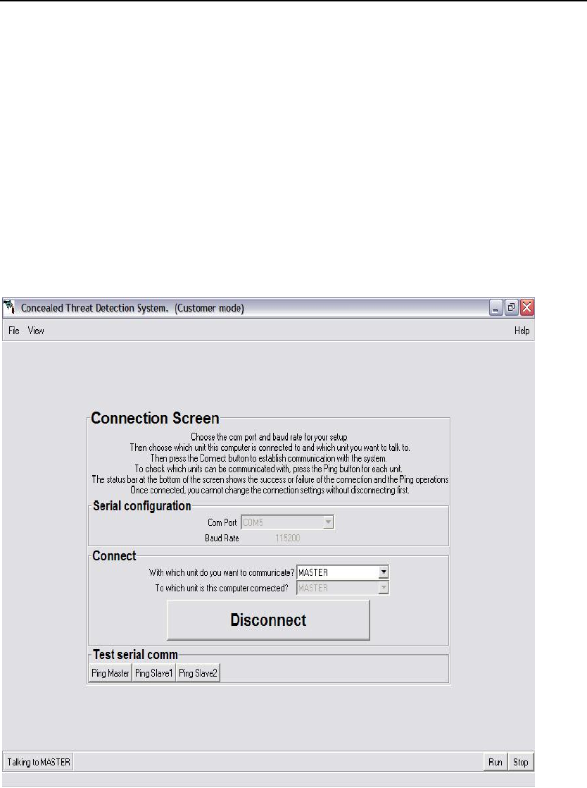
1. Go to the Connection Screen—Connections area
With which unit do you want to communicate?
Choose Master
Selecting Master on Connection Screen.
2. Go to the Configuration Screen (select it from the View menu at the top of the
Connection Screen).
Installation and Operations Manual 44
Safe Zone Systems ◘ Concealed Threat Detection System
Selecting number of units on Configuration Screen.
3. Go to the Unit configuration area, Number of units in system
Select the number of units from the list. This only needs to be done on the Master unit.
4. Save by selecting Set current config as default.
Installation and Operations Manual 45
Safe Zone Systems ◘ Concealed Threat Detection System
Changing the Designation of a Unit
You can change a CTD unit’s designation. For example, you can change a unit
designated as Slave 1 to Slave 2.
1. Go to the Connection Screen—Connections area
With which unit do you want to communicate?
Choose the unit you want to change (Master, Slave 1 or Slave 2)
Selecting Master (or another unit) on Connection Screen.
2. Go to the Configuration Screen (select it from the View menu on the Connection
Screen).
Installation and Operations Manual 46
Safe Zone Systems ◘ Concealed Threat Detection System
Selecting a unit’s designation.
3. Go to the Unit configuration area, this unit’s designation.
Select the new designation for the unit you selected on the Connection screen.
4. A confirmation dialog box will open asking if you are sure you want to make this
change. If so, click yes and this will save the new designation as the default.
Installation and Operations Manual 47

Safe Zone Systems ◘ Concealed Threat Detection System
Changing the Settle Time
You can change how long the CTD system allows for a test subject to get settled in the
Test Area before the test starts.
1. Look at the bottom left corner of any software screen and make sure that the system
is communicating with the Master CTD.
Communicating with Master unit.
2. Go to the Configuration Screen (select it from the View menu).
Installation and Operations Manual 48

Safe Zone Systems ◘ Concealed Threat Detection System
Installation and Operations Manual 49
Changing the target settle time on the Configuration Screen.
3. Go to the Timing for test sequence section.
Enter the number of milliseconds you would like for the target settle time. The factory
default is 2000 milliseconds (2 seconds).
4. Save the new Target settle time by selecting Set current config as default.

Safe Zone Systems ◘ Concealed Threat Detection System
Changing the Sound Beep Time
You can change how long the beep signaling completion of a test sounds. This beep
can only be heard if your CTD system includes the optional display box.
1. Look at the bottom left corner of any software screen and make sure that the system
is communicating with the Master CTD.
Communicating with Master unit.
2. Go to the Configuration Screen (select it from the View menu).
Installation and Operations Manual 50
Safe Zone Systems ◘ Concealed Threat Detection System
Installation and Operations Manual 51
Changing the sound beep time on the Configuration Screen.
3. Go to the Display Parameters section of the screen.
4. Enter the number of milliseconds you would like the beep to sound. The factory
default is 200 milliseconds. (0.2 seconds)
5. Save by selecting Set current config as default.
Safe Zone Systems ◘ Concealed Threat Detection System
Changing System Sensitivity (Thresholds)
The sensitivity of the testing process is set at the factory. However, you can change the
settings if you would like to make the testing process more or less sensitive. You might
do this if you feel you are getting too many false positives, for example. To learn more
about the test process, see Appendix B.
1. Look at the bottom left corner of any software screen and make sure that the system
is communicating with the Master CTD.
Communicating with Master unit.
2. Go to the Configuration Screen (select it from the View menu).
Installation and Operations Manual 52
Safe Zone Systems ◘ Concealed Threat Detection System
Changing the Test Parameters on the Configuration Screen.
3. Go to the Test Parameters section of the screen.
The Weapon Threshold is the score below which a Safe decision will be rendered for
any single reading. The Sum Threshold is the score below which a Safe decision will be
rendered for the sum of three readings. The Sum Threshold does not need to be set at
three times the Weapon threshold. A value that is 10 to 20% less than three times the
single reading (Weapon) threshold can give more accurate results in some situations.
4. Change settings
• To increase the sensitivity of the readings, lower the Weapon Threshold number
and/or Sum Threshold number.
• To decrease the sensitivity of the readings, raise the Weapon Threshold number
and/or Sum Threshold number.
5. Save by selecting Set current config as default.
Installation and Operations Manual 53
Safe Zone Systems ◘ Concealed Threat Detection System
Returning the System to Default Settings
If you have made changes to the system software but want to return to the original CTD
system settings, you can restore the default settings.
1. Look at the bottom left corner of any software screen and make sure that the system
is communicating with the Master CTD.
Communicating with Master unit.
2. Go to the Configuration Screen (select it from the View menu).
Installation and Operations Manual 54

Safe Zone Systems ◘ Concealed Threat Detection System
Installation and Operations Manual 55
Restoring defaults on the Configuration Screen.
3. Go to the Save/Load from disk section of the screen.
4. Select Load config file from disk. A file browser window will open. Choose the
configuration directory. Choose “factory defaults.txt” and press Open.
5. Go to the Set/Restore defaults section of the screen. Click set current config as
default.

Safe Zone Systems ◘ Concealed Threat Detection System
Changing the Operating Distance
To change the operating distance or range for your CTD system, you will need to obtain
a new neural networking training set from the factory. If you get new software and/or
hardware from the factory, you will be given instructions on how to install it.
If you are going to be using the system at extremely long or short ranges (operating
distances that are not between 9 and 15 feet / 2.7meters to 4.5meters), you may also
need to get a different antenna.
Contact your local sales representative for details.
Changing the Neural Network
If you want to allow the CTD system to detect different objects, or work in cluttered
environments, the neural network must be retrained for a specific installation or purpose.
Neural network training is done at the factory, but new training data can be loaded into
your units in the field by using the Load config from disk button on the Configuration
screen.
Contact your local sales representative for details.
Installation and Operations Manual 56
Safe Zone Systems ◘ Concealed Threat Detection System
SOFTWARE REFERENCE
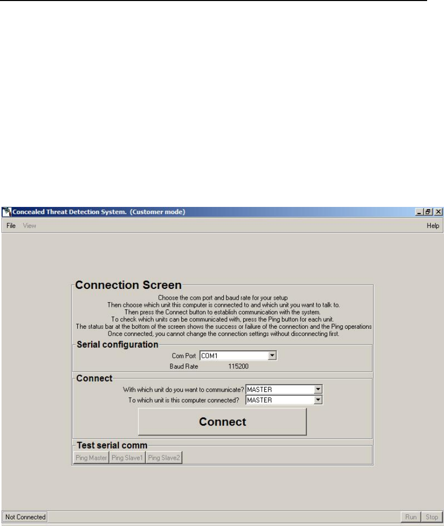
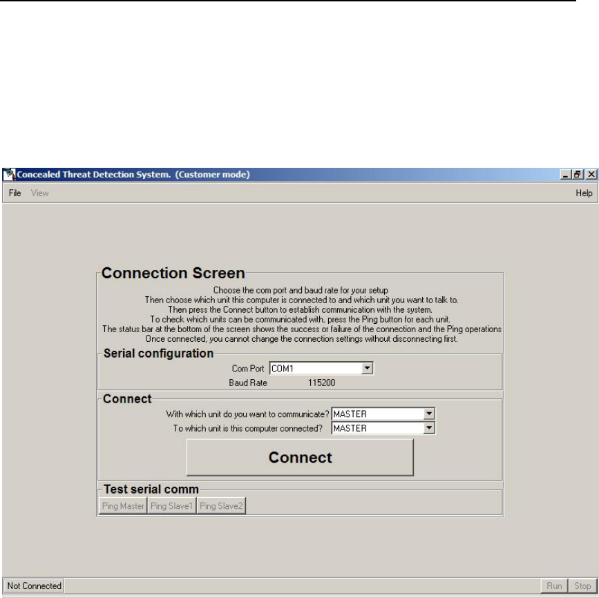
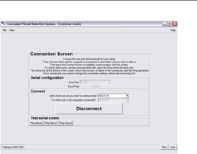
Connection Screen
Connection Screen when Not Connected.
Connection Screen (Not Connected)
Serial configuration section
COM Port
Choose the COM Port for your setup. Use the pulldown menu to select
one of the COM Ports listed.
Baud Rate
The baud rate is set at 115200. You cannot change this setting.
Installation and Operations Manual 57

Safe Zone Systems ◘ Concealed Threat Detection System
Connect section
With which unit do you want to communicate?
Choose which unit you want to communicate with from the pulldown menu.
You can choose from any of the units your system includes: Master,
Slave 1 or Slave 2.
To which unit is the computer connected?
Choose which unit you have your computer connected to. You can
choose from any of the units your system includes: Master, Slave 1 or
Slave 2.
Connect button
Press Connect when you have made your selections in the connect section
and are ready to connect your computer to the system.
Installation and Operations Manual 58
Safe Zone Systems ◘ Concealed Threat Detection System
Connection Screen when Connected.
Connection Screen (Connected)
Top menu bar
View
Click on View at the top left of the screen to see the dropdown menu and
access other CTD software screens.
File
Click on File at the top left of the screen to see the dropdown menu and
access File functions such as Save.
Installation and Operations Manual 59

Safe Zone Systems ◘ Concealed Threat Detection System
Connect Section
Disconnect
Press Disconnect to sever connections between your computer and the
CTD system.
Note: If you are Connected, the Serial configuration and Connections items will be
disabled. If you want to change them, you have to Disconnect by pushing the
Disconnect button.
Test Serial Comm section
Ping Master
Ping Slave 1
Ping Slave 2
These buttons let you test the serial communications between CTD system
unit(s)
Bottom menu bar
Run
Push Run to prepare the system to run tests. Your computer will be
switched to the Status Screen. You will see the same status and test result
information on your portable computer as is shown on the Operator
Monitor. However, your computer will not display the video picture.
Stop
Push Stop to take the system out of the run tests mode.
Installation and Operations Manual 60
Safe Zone Systems ◘ Concealed Threat Detection System
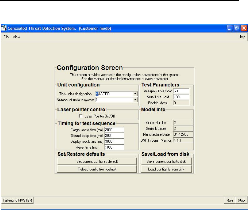
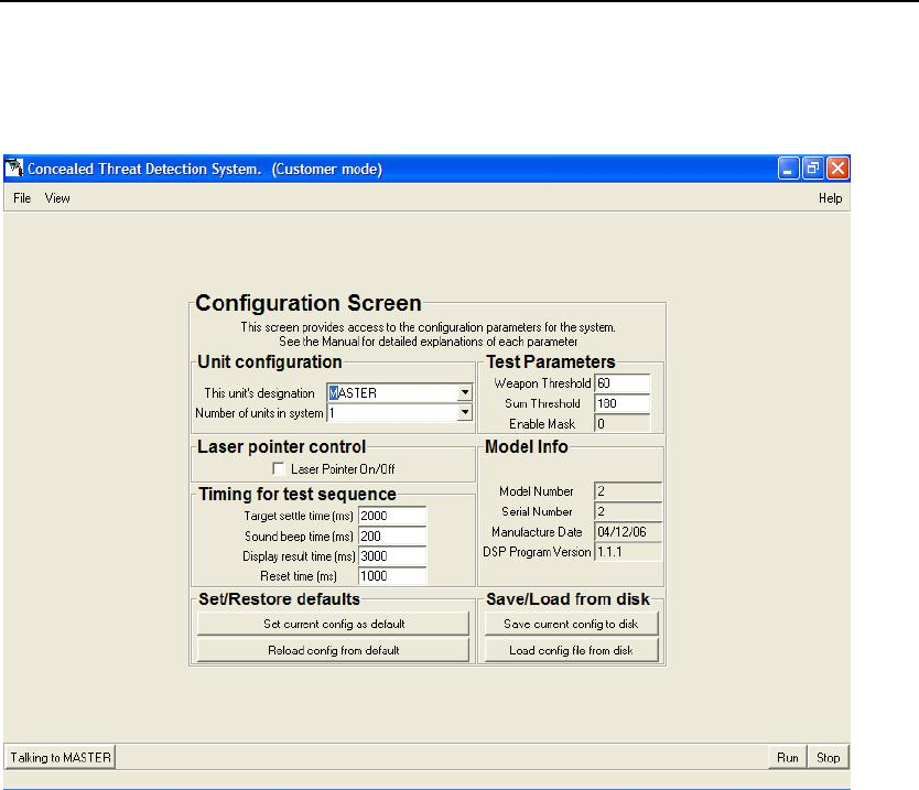
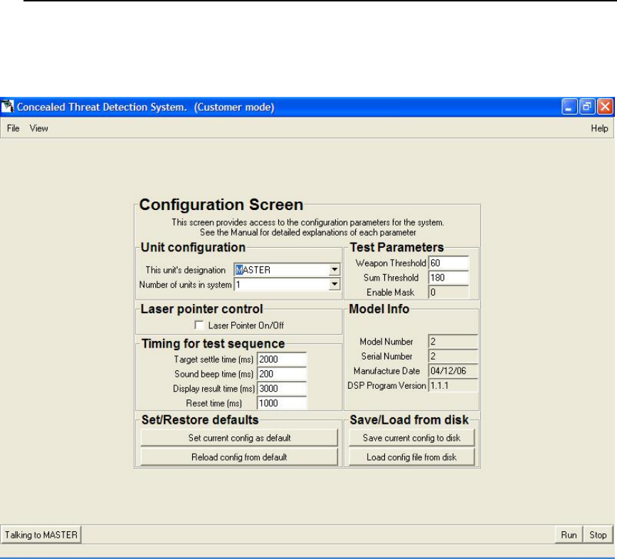
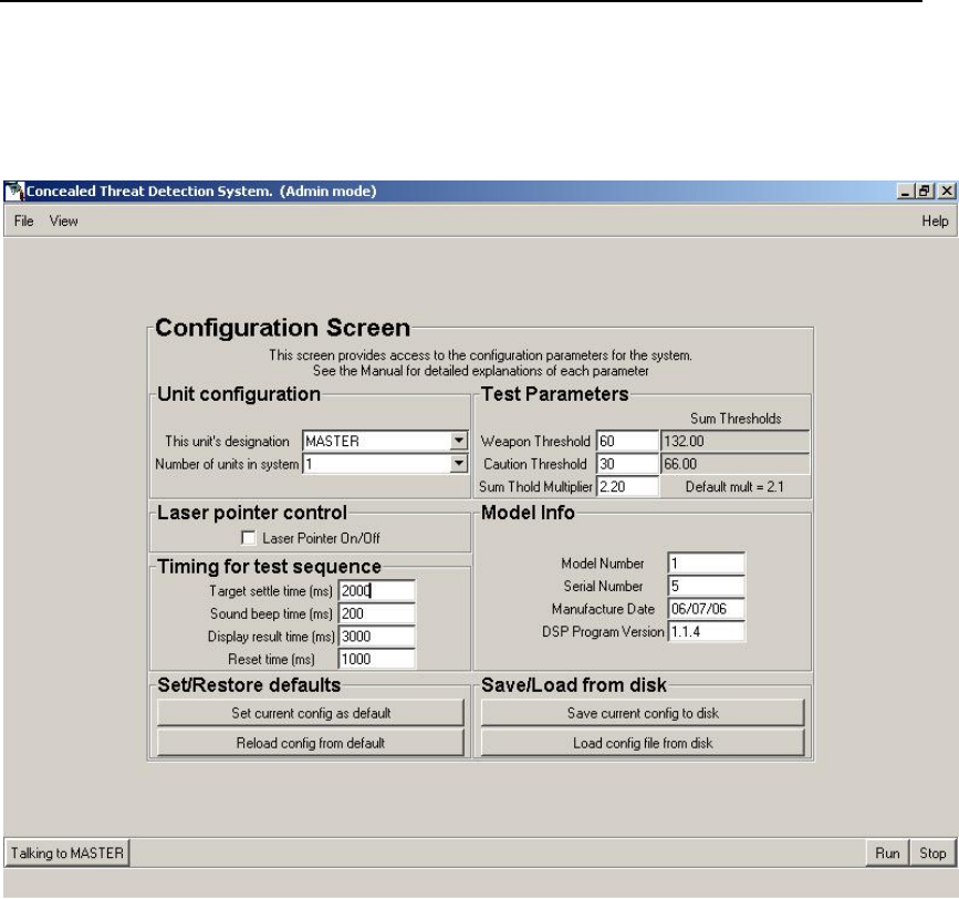
Configuration Screen
Configuration Screen.
Configuration Screen
Unit Configuration section
This unit’s designation
Here you can choose whether a unit will be designated as the Master,
Slave 1 or Slave 2. Use the pulldown menu.
Number of units in system
Here you use the pulldown menu to select change the number of units in
your CTD system.
Laser pointer control
You can check this box to turn the laser pointer on or off.
Installation and Operations Manual 61

Safe Zone Systems ◘ Concealed Threat Detection System
Timing for test sequence section
All settings in this section are in milliseconds (thousandths of a second).
Target settle time
You can adjust the time allowed for the test subject to get in position before the
test begins. If you find that subjects are not ready to be in the proper position,
standing still before the radar begins scanning, you can increase the target settle
time from what is set as the default.
Sound beep time
Here you can adjust the time that the beep signaling the end of the test sounds.
This beep can only be heard if your CTD system includes the optional display
box.
Display result time
Use this control to change the amount of time that the test result is displayed on
the monitor(s)
Reset time
Here you can adjust the amount of time it takes to reset the system between
tests.
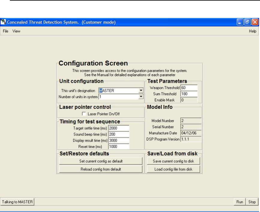
Test Parameters
Weapon Threshold
The Weapon Threshold is the score above which a Threat decision will be
rendered for any single reading. However, the CTD system requires two out of
three readings above this threshold for a Threat decision to be called.
• To increase the sensitivity of the readings, lower the Weapon Threshold number.
• To decrease the sensitivity of the readings, raise the Weapon Threshold number.
Caution Threshold
The Caution Threshold is the score above which a Caution decision will be
rendered for any single reading, provided that the scores are less than the Threat
Threshold.
Note: It is very possible for the scores of three separate readings to be in the
Caution range, but for their sum to exceed the Weapon Sum Threshold. In that
case, a Threat decision will be rendered. See the section on the Sum Threshold
Multiplier below, as well as Appendix B for more information.
• To increase the sensitivity of the readings, lower the Caution Threshold number.
• To decrease the sensitivity of the readings, raise the Caution Threshold number.
Installation and Operations Manual 62

Safe Zone Systems ◘ Concealed Threat Detection System
Sum Threshold Multiplier (Sum Thold Multiplier)
The Sum Threshold Multiplier is a number that is multiplied by the numbers
selected for the Caution and Weapon Thresholds. The resulting Sum Thresholds
are compared to the sum of the readings taken on a particular test subject.
If the sum of the readings exceeds the Caution or Weapon Sum Threshold, a
Caution or Threat screen will be displayed. This provides a second way of
scoring subjects to increase the CTD system’s accuracy.
The multiplier requires a minimum of two decimal places, and should be a
number between 2.00 and 3.00. The default value for the multiplier is 2.1.
Example: You set your Caution Threshold to 50 and your Weapon Threshold to
60. Your Sum Threshold Multiplier is set to 3.0. A test subject returns scores of
95, 50 and 50. You will get a Threat Screen even though two out of three of the
numbers are below your Weapon Threshold. This is because the Sum of the
multiplier times the Weapon Threshold (3 x 60 = 180) has been exceeded by the
sum of the three readings (195).
• To increase the sensitivity of the readings, lower the Sum Threshold Multiplier
number.
• To decrease the sensitivity of the readings, raise the Sum Threshold Multiplier
number.
When you save a new Sum Threshold Multiplier to disk, the Weapons Sum
Threshold and Caution Sum Threshold in the right column will be updated.
Enable Mask
This setting is set at the factory and cannot be changed.
Model Info section
These settings are set at the factory and cannot be changed by the user.
Set/Restore defaults section
Set current config as defaults
Use this button to save the changes you’ve made to various settings on the
Configuration Screen and have them become your new default settings.
Reload config from default
Use this button to restore the system defaults from memory. This will return the
system back to the settings that were set by the factory as defaults.
Installation and Operations Manual 63

Safe Zone Systems ◘ Concealed Threat Detection System
Save/Load from disk section
Save current config to disk
Use this button to save your current system configuration to a location in your
hard drive or on some other memory device.
Load config file from disk
Use this button to load a new configuration file that you may have received from
the factory into your CTD system.
Installation and Operations Manual 64
Safe Zone Systems ◘ Concealed Threat Detection System
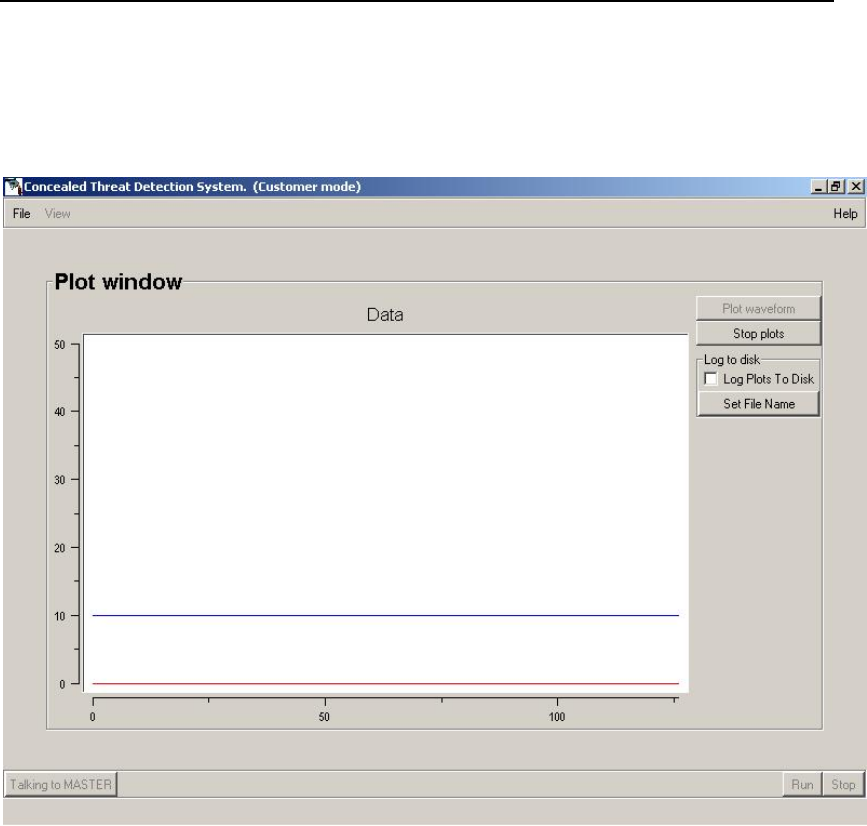
Plot Window
Plot window.
Plot window
Plot waveform
Click plot waveform to start the plotting process.
Stop plot
Click Stop plot to stop the plotting process.
Log to disk section
Log plots to disk checkbox
Check this box to record the plot waveforms. This can be helpful when
requesting remote assistance in diagnosing a situation.
Set File Name
Use this to name the recorded plotting data.
Installation and Operations Manual 65

Safe Zone Systems ◘ Concealed Threat Detection System
SERVICE AND MAINTENANCE
Replacement Parts
• Processor board
• Camera assembly
• Power supply board
• Interface connector board
• Microwave assembly
• Antenna
Technical Support
Contact your local sales representative with any technical questions. If you need to find
out who your local rep is, you can find their contact information at
www.safezonesystems.com/contact.html.
Installation and Operations Manual 66

Safe Zone Systems ◘ Concealed Threat Detection System
APPENDICES
Appendix A Clutter
As with any radar, the low-power radar in the Safe Zone CTD transmits a signal and
reflections of that signal are received and processed. In this case, we are interested in
the reflections caused by a small object (such as a gun or shrapnel) that is mounted on a
larger object, a human body. The body has a larger return than the object of interest.
Therefore, very sophisticated processing is needed to separate the two sources of
reflection. This requires the reflections to not contain contamination from extraneous
items. Thus, the area in which the subject is being examined should not contain close by
objects that will add random reflections to the return signal.
In some cases, such objects, referred to as clutter, may not be visible or apparent.
Examples of visible clutter are structural columns, furniture, trash cans, etc. Non-visible
clutter can be ceiling gratings, air conditioning ductwork, rebar in concrete floors, steel
studs in walls and other hidden plumbing. Therefore, one must consider the environment
when setting up a radar-based system. In particular, when the units are stood on a table
that has metal bars below the surface for strength, the antenna should be forward of
those bars.
If you are having problems detecting non-visible clutter, please contact your sales
representative. They can offer assistance by measuring the hidden clutter using
proprietary Safe Zone software.
Installation and Operations Manual 67

Safe Zone Systems ◘ Concealed Threat Detection System
Appendix B The Testing Process
The Safe Zone Concealed Threat Detection System uses a neural network (pattern
recognition software) to calculate a score representing the probability that a subject has
a weapon on his or her body.
A complete measurement consists of three rapidly consecutive readings. Each reading
produces a score between 0 and 99. If two out of three readings exceed the set Caution
threshold (e.g. 50), a Caution decision is rendered and a Caution (yellow) screen is
displayed. If two out of three readings exceed the set Weapon Threshold (e.g. 60), a
Threat decision is rendered and a Threat (red) screen is displayed.
Additionally, the Caution and Threat threshold numbers are multiplied by the Sum
Threshold Multiplier. The resulting Sum Thresholds are compared to the sum of the
readings taken on a particular test subject.
If the sum of the readings exceeds the Caution or Weapon Sum Threshold, a Caution or
Threat screen will be displayed. This provides a second way of scoring subjects to
increase the CTD system’s accuracy.
Example: You set your Caution Threshold to 50 and your Weapon Threshold to 60.
Your Sum Threshold Multiplier is set to 3.0. A test subject returns readings of 95, 50
and 50. You will get a Threat Screen even though two out of three of the numbers are
below your Weapon Threshold. This is because the Sum of the Multiplier times the
Weapon Threshold (3 x 60 = 180) has been exceeded by the sum of the three readings
(195). Note: It is very possible for the scores of three separate readings to be in the
Caution range, but for their sum to exceed the Weapon Sum Threshold. In that case, a
Threat decision will be rendered.
To see what your CTD system’s Threshold settings are, look at the CTD Software
Configuration screen’s Test parameters area.
Installation and Operations Manual 68
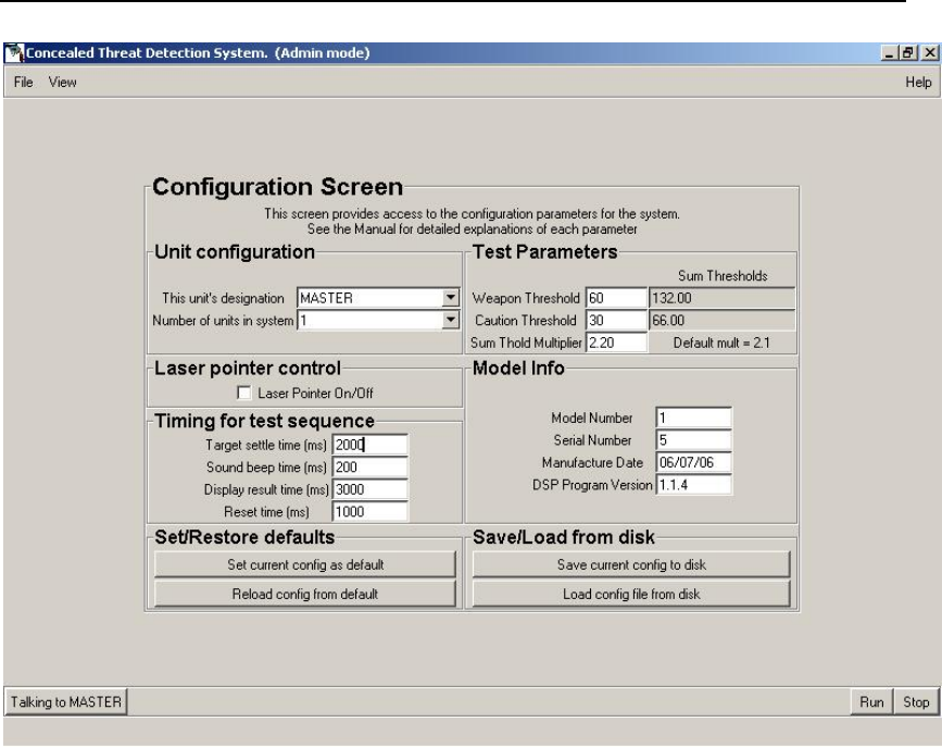
Safe Zone Systems ◘ Concealed Threat Detection System
Checking the Test Parameter settings on the Configuration Screen.
If you want to change the thresholds because, for example, you feel your CTD system is
returning too many false positives, you can adjust it using the CTD software. See
Optimizing the System, Changing System Sensitivity and/or the Configuration Screen
explanation in the Software Reference section of this manual.
Installation and Operations Manual 69
Safe Zone Systems ◘ Concealed Threat Detection System
Appendix C Radiation Safety
The CTD is a spread spectrum radar operating in the range of 10 GHz. Because it is a
low-power radar, it is very safe.
The average cell phone puts out four times as much power as the CTD system. Plus,
the cell phone is much closer to the user than the CTD system is to the test subjects.
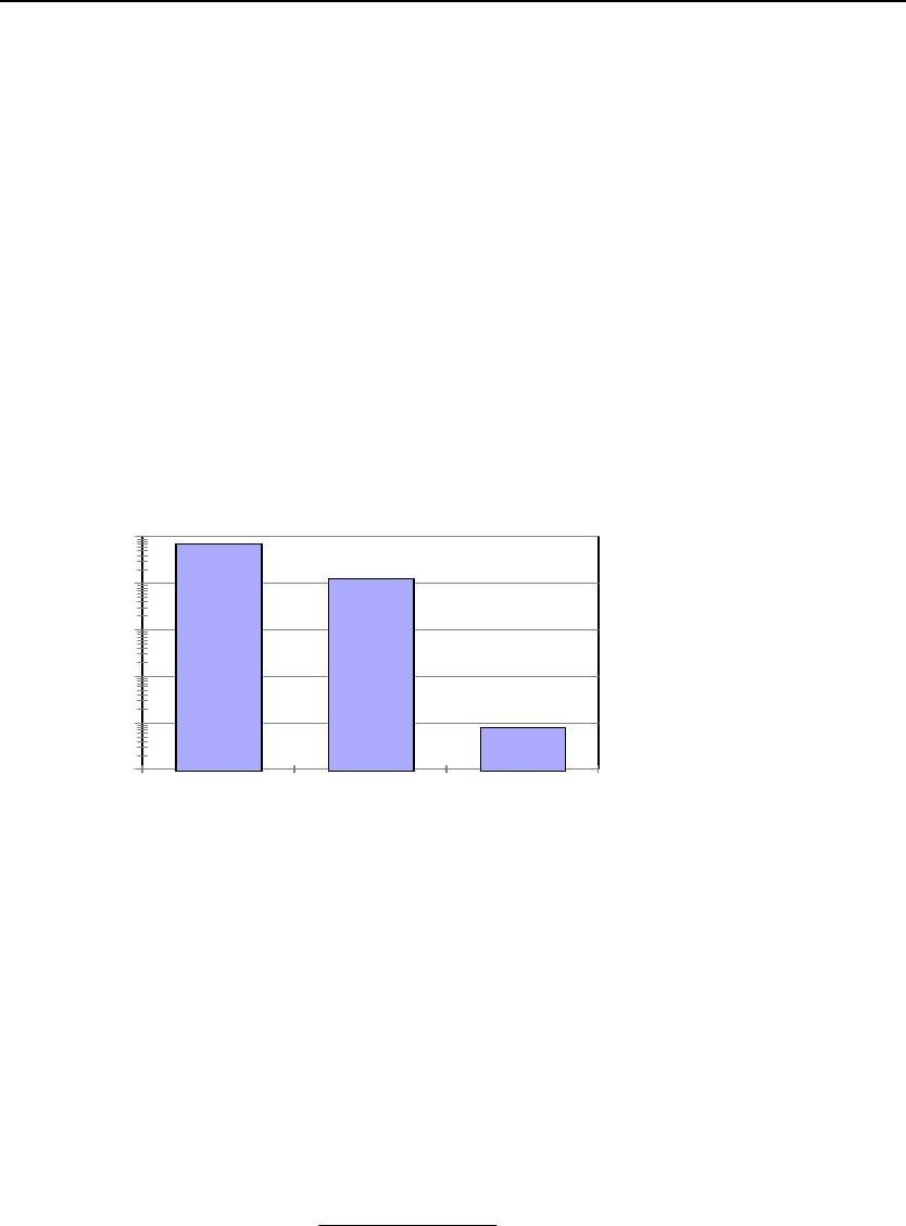
The CTD system operates at 1 / 10,000 of the safe level as defined by ANSI. Also, keep
in mind that the ANSI standard is for radiation exposure of six minutes but the CTD gives
test subjects only about 6 seconds of exposure.
0.0001
0.001
0.01
0.1
1
10
mw/sq cm
ANSI Safety Std
Cell Phone SZS CTD
Radiated Power Density
Logarithmic Comparison
Note that the vertical scale is logarithmic and the CTD-created radiation is on the order
of 1/10,000th of the safe level. If a linear scale is used, the CTD radiated level is too
small to be seen.
Formula
The typical range to target is 3 meters (300 cm). The peak transmitted power is 0.1 watts
and the antenna gain is 19 dB (numeric = 79). The waveform is interrupted CW with
about a 10% duty factor. The power density at a given target range is
P
P
G
R
dt
=
42
Π
Using these values, the power density at the target (or subject) is 7 X 10⁻⁶ watts per
square centimeter, or 7 X 10⁻³ milliwatts/cm2.
Installation and Operations Manual 70
Safe Zone Systems ◘ Concealed Threat Detection System
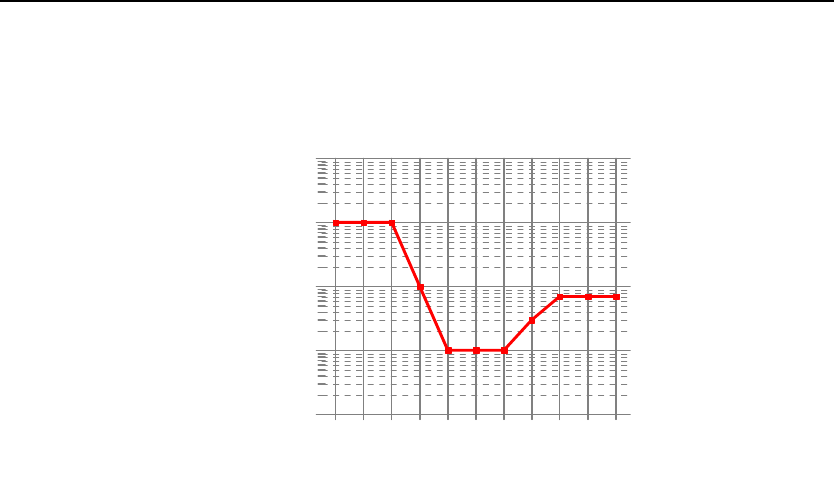
The ANSI C95.1-1982 Standard for full body illumination is shown in the ANSI diagram.
Note that this is for a 6 minute average. The maximum allowable value at 10 GHZ is
about 7mW/cm2. The Safe Zone CTD peak power is three orders of magnitude below
this figure, and when multiplied by the duty cycle to arrive at average power, the
exposure is about 7 X 10⁻⁴ mW/cm2. This is a safety margin of 4 orders of magnitude. As
the range is increased, the power density falls off in proportion to the square of the
range.
1E-1
1E0
1E1
1E2
1E3
mW/cm sq
0.3 10 300 10000
Frequency (MHz)
US ANSI C95.1-1982 Standard
Whole Body Radiation-6 minute average
Installation and Operations Manual 71

Safe Zone Systems ◘ Concealed Threat Detection System
Appendix D Technical Background on the CTD system
Radar
The Safe Zone CTD’s radar operates over a broad frequency range centered at 10GHZ.
It transmits a signal that is horizontally polarized, meaning that the electric field portion of
the electromagnetic wave is in the horizontal direction. When the wave is reflected from
a body, most of the reflected signal is returned in the same polarity, but some is
converted to vertical polarization (referred to as cross-pol), primarily due to the bone
structure of the body. Objects outside of the body, whether they are metallic or of a fairly
high dielectric constant, create a polarity conversion and return a significantly higher
amount of cross-pol than the body itself. The two polarity signals are separated at the
CTD and are independently received and processed.
Neural Network
When the return signals from the radar are received, they are mathematically processed
and a number of parameters are extracted and observed by the neural network (pattern
recognition software). At the factory, a number of people are tested using the CTD
system and their results are recorded. These people are tested in Safe and Threat
conditions. The information is fed to the neural network with the correct answer for each
person and condition. The pattern recognition software then weights the various
parameters for later use.
Installation and Operations Manual 72

Safe Zone Systems ◘ Concealed Threat Detection System
Glossary
clutter. Undesired objects causing undesired radar returns that tend to mask the
desired return. Clutter can be visible or nonvisible. For more information, see
Appendix A.
CTD. Concealed Threat Detection system.
measurement. A series of two or three readings that results in a test score.
neural network. Also called pattern recognition software. The CTD’s software includes
a neural network which allows it to compare test subject scans against those it has
learned previously in order to render a safe or threat reading. For more information, see
Appendix D.
reading. A number of sweeps, the results of which are averaged and combined.
system. A group of CTD radar units along with associated display and interface
equipment.
test subject. The person being tested by the CTD system.
test area. The area designated for the test subject to stand while being tested by the
CTD system. In order for the CTD system to take accurate readings, this area needs to
be a specific distance from the system components.
unit. (or CTD unit) A single radar instrument in the CTD system which can be
designated as Master, Slave 1 or Slave 2.
Safe Zone Systems
7700 Ouray NW
Albuquerque, New Mexico 87120
USA
www.safezonesystems.com
Safe Zone Concealed Threat Detection System is a trademark of Safe Zone Systems, Inc.
Installation and Operations Manual 73

Safe Zone Systems ◘ Concealed Threat Detection System
Warranty and Disclaimer
This product is warranted to be free of manufacturing and material defects for a period of
six (6) months from the date of shipment. If defects are discovered, contact Safe Zone
support for a resolution of the problem or a return authorization. Safe Zone will repair or
replace a defective unit at Safe Zone’s discretion. This warranty does not cover
damages inflicted by improper handling, customer neglect or operation in a manner for
which the product was not intended.
Safe Zone will not pay for loss of time, inconvenience, loss of use of your Safe Zone
product, damage to property or personnel or other incidental or consequential damages.
This warranty does not cover defects resulting from accidents, damage while in-transit to
our service location, alterations, unauthorized repair, failure to follow instructions,
misuse, fire, flood, and acts of God. We suggest that you retain your original packing
material in the event you need to ship your Safe Zone product. When sending your Safe
Zone product to a service location, include your name, address, phone number, proof of
date of purchase, and a description of the operating problem.
A Word about Concealed Material Detection
The Safe Zone Systems Concealed Threat Detector (CTD) has been designed to detect
unusual items hidden under people’s clothing from a standoff position. While it has a
high degree of accuracy, like any other detection equipment, the detection rate is not
100%. Laboratory testing and data collected from various field tests have shown
detection rates of 95% or better. As such, it is intended to be used as a first line
examination of people approaching a checkpoint or controlled area. It is not intended to
replace metal and trace chemical detectors.
The CTD has been calibrated and thresholds have been selected to automatically
produce an indication as to whether the artificial intelligence used for this process
decided upon a threat or safe condition. There are, naturally, conditions and items that
can produce a false reading in either a safe or threat condition. The effectiveness of the
system can be enhanced by introducing some level of human intelligence and decision-
making capability. That capability is offered to the user via a scoring system, or certainty
factor. This information can be viewed on the output signal, in the form of composite
video, which can be directly connected to a video monitor. Data is constantly being
collected to permit software upgrades to minimize the automated decision errors. These
upgrades will be announced as they become available.
Depending on the degree of security being sought at a particular location, the correct
combination of technologies needs to be selected. A security expert should be
consulted to aid in that selection. The CTD uses radar technology which can be
combined with metal detection, chemical vapor or trace detection and millimeter
scanning or array imaging. Each technology has its own advantages and drawbacks,
but the correct combination can offer an extremely high level of security.
Installation and Operations Manual 74