Safety Instruments ILUVMYZ7 Viking Z Seven SCBA User Manual Avon Viking Z Seven6 07
International Safety Instruments, Inc. Viking Z Seven SCBA Avon Viking Z Seven6 07
Users Manual

COPYRIGHT 2007 AVON - ISI 1
PREFACE
WARNINGS, CAUTIONS AND NOTES
Please read all carefully.
Failure to properly use and maintain this
product could result in injury or death.
INTENT
This manual is intended to acquaint owners and users with
the operation of the VIKING Z SEVEN, CBRN models of Self-
Contained Breathing Apparatus, and to provide important
safety information and limitations. All information, illustrations
and specifications in this manual are based on the latest
product information available at the time of printing. The right
is reserved to make changes at any time without notice.
IMPORTANT
ALL PERSONNEL USING THIS APPARATUS SHALL BE
THOROUGHLY TRAINED BY A QUALIFIED INSTRUCTOR
IN DONNING, OPERATION, INSPECTION AND EMERGEN-
CY OPERATION.
Equipment should be thoroughly INSPECTED, FUNCTION-
ALLY checked and cleaned after EACH exposure to intense
heat or harsh chemicals. UNDER A KNOWN CBRN CON-
TAMINATION EXPOSURE, proper DECONTAMINATION
AND DISPOSAL PROCEDURES MUST BE FOLLOWED in
accordance with local government instructions and/or proce-
dures. IF CONTAMINATED WITH LIQUID CHEMICAL WAR-
FARE AGENTS, DISPOSE OF THE SCBA AFTER DECON-
TAMINATION.
The VIKING SCBA is designed to be simple to use and easy
to maintain and will operate for many years if properly main-
tained and cleaned. The instructions for care and use given
in this manual must be read, understood and carefully fol-
lowed before the apparatus is used.
The procedures in this manual DO NOT render AVON-ISI lia-
ble for any losses or injury arising from any actions based on
use of same.
Spare parts and accessories are available through your local
AVON-ISI authorized distributor. Service beyond the scope of
this manual is not recommended. If a problem persists, the
apparatus should be removed from service, tagged for repair,
and forwarded to an AVON-ISI Certified Service Center or to
the AVON-ISI factory for evaluation and/or repair. Do not
mark the unit with inks or paints, which might be flammable,
or cover any approved labels, such as NIOSH labels.
TRAINING
AVON-ISI strongly recommends that the training program
used be consistent with NFPA 1500, Standard on Fire De-
partment Occupational Safety and Health Programs and
NFPA 1852, Standards on Selection, Care, and Maintenance
of Open –Circuit SCBA’s. Training and servicing programs
are available upon request. Please contact AVON-ISI or your
local distributor for further details.
APPROVALS
All Viking Z SEVEN SCBA are CBRN certified and NIOSH ap-
proved, meeting the NFPA 1981 Standard, 2007 Edition and
the NFPA 1982 Standard, 2007 Edition (when equipped with
PASS) requirements.
NIOSH/OSHA WARNINGS
The following warnings are given in accordance with accept-
ed safety conventions and/or NIOSH/OSHA requirements,
and apply to the use of breathing apparatus in general.
HEALTH LIMITATIONS: Wearers of the SCBA should be
certified medically fit prior to use. In addition, there are both
physiological and psychological limitations which should be
considered before using SCBA. They include, but are not lim-
ited to:
• Emphysema
• Chronic obstructive pulmonary disease
• Bronchial asthma
• X-ray evidence of pneumonia
• Evidence of reduced pulmonary function
• Coronary artery disease
• Severe or progressive hypertension
• Epilepsy (grand mal or petit mal)
• Pernicious anemia
• Diabetes (insipidus or mellitus)
• Breathing difficulties when wearing an SCBA
• Claustrophobia or anxiety when wearing an SCBA
• Abnormal EKG results from resting or stress tests
• Punctured or ruptured ear drum
WORKING TEMPERATURES: The VIKING SCBA is ap-
proved for respiratory protection during entry into or escape
from oxygen deficient atmospheres, gases, and vapors at
temperatures above -25°F. When used below freezing, care
must be exercised to prevent moisture from entering the de-
mand exhalation valve. The facemask should remain on the
docking hook when not in use. On the AirSwitch model, the
slide should be stored in the up position when not in use. For
the RDV demand valve, the RDV should be stored on the
docking station found on the waistbelt. This includes when
cylinders are being changed.
DURATION OF USE: Although the VIKING has been ap-
proved as either a 30-minute, 45-minute, or 60-minute breath-
ing apparatus, the wearer’s varying work rate, physical condi-
tion and other factors could substantially shorten the actual
usable duration of the unit.
SCBA LIMITATIONS: An SCBA can only protect the wear-
er’s respiratory system. Other protection may be neces-
sary to avoid contamination through skin absorption. If
these types of materials are suspected, an effective full-
body covering of impermeable material must be worn
with the SCBA. A universal Level A HazMat suit is avail-
able for the VIKING SCBA from HazMat suit manufactur-
ers.
FACIAL HAIR: Facial hair or any other items which may in-
terfere with the facemask-to-face seal, including the nosecup,
or the operation of the exhalation valve, must not be allowed.
These include beards, sideburns, mustaches, bangs, head
coverings, or anything else that may interfere with the correct
seal of the facemask and/or nosecup to the face.
COPYRIGHT 2007 AVON - ISI
2
EYE WEAR: Eye glasses shall not be used when the temple
bars interfere with the proper seal of the facemask to the
face. If a user must wear corrective lenses while wearing the
SCBA, they can be mounted in the facemask using a special
lens mounting kit (AVON-ISI p/n 136003) available from
AVON-ISI or through your local AVON-ISI authorized distribu-
tor.
MANUAL BYPASS: In compliance with NIOSH requirements,
the Viking SCBA has a manually operated bypass which pro-
vides a continuous flow of air to the facemask when required,
independent of normal operation of the regulator. The bypass
is opened by turning the red knob on the AirSwitch 90 de-
grees in the direction shown by the knob arrow. The RDV by-
pass opens by turning towards the user. Use of the bypass
will shorten the duration of the SCBA.
CAUTIONS AND LIMITATIONS FOR VIKING
Z SEVEN MODEL
D - Airline respirators can be used only when the respirators are supplied
with respirable air meeting the requirements of CGA G-7.1 Grade D or
higher quality.
E - Use only the pressure ranges and hose lengths specified in the User's
Instructions.
I - Contains electrical parts which have not been evaluated as an ignition
source in flammable or explosive atmospheres by MSHA/NIOSH.
J - Failure to properly use and maintain this product could result in injury
or death.
M - All approved respirators shall be selected, fitted, used and maintained in
accordance with MSHA, OSHA, and other applicable regulations.
N - Never substitute, modify, add, or omit parts. Use only exact replacement
parts in the configuration as specified by the manufacturer.
O - Refer to User's Instructions and/or maintenance manuals for information
on use and maintenance of these respirators.
S - Special or critical User's Instructions and/or specific use limitations
apply. Refer to User's Instructions before donning.
CAUTIONS AND LIMITATIONS FOR VIKING Z SEVEN
MODEL WITH CBRN PROTECTION APPROVAL
I - Contains electrical parts which have not been evaluated as an ignition
source in flammable or explosive atmospheres by MSHA/NIOSH.
J- Failure to properly use and maintain this product could result in injury
or death.
M - All approved respirators shall be selected, fitted, used and maintained in
accordance with MSHA, OSHA, and other applicable regulations.
N - Never substitute, modify, add, or omit parts. Use only exact replacement
parts in the configuration as specified by the manufacturer.
O - Refer to User's Instructions and/or maintenance manuals for information
on use and maintenance of these respirators.
S - Special or critical User's Instructions and/or specific use limitations
apply. Refer to User's Instructions before donning.
Q - Use in conjunction with personal protective ensembles that provide
appropriate levels of protection against dermal hazards.
R - Some CBRN agents may not present immediate effects from exposure,
but can result in delayed impairment, illness or death.
T - Direct contact with CBRN agents requires proper handling of the SCBA
after each use and between multiple entries during the same use.
Decontamination and disposal procedures must be followed. If
contaminated with liquid chemical warfare agents, dispose of the SCBA
after decontamination.
U - The respirator should not be used beyond 6 hours after initial exposure
to chemical warfare agents to avoid possibility of agent permeation.
WARNING
ONLY THOSE SCBA UNITS THAT DISPLAY THE
BELOW LABEL ON THE BACKFRAME AT THE AT-
TACHMENT OF THE CYLINDER SPOON ARE CERTI-
FIED AS CBRN AGENT APPROVED.
Note: If your department has both CBRN and non-CBRN ap-
proved units, be sure to check the backframe for this label
prior to donning an SCBA when using in environments where
there is the possibility of cbrn agents being
present. Failure to do so may result in
injury or death.
AVON-ISI ALSO DISPLAYS THIS
CBRN LABEL ON THE FACEMASK
OF CBRN AGENT APPROVED
UNITS. THE CBRN FACEMASK LA-
BELS ARE LOCATED INSIDE THE VISOR ON BOTH
THE RIGHT AND LEFT LOWER CORNERS.
ANY FACEMASK THAT DOES NOT HAVE THIS
ABOVE LABEL ON THE INSIDE VISOR SHOULD
NOT BE USED IN ENVIRONMENTS WHERE THERE
IS THE POSSIBILITY OF CHEMICAL WARFARE
AGENTS BEING PRESENT.
FACEMASKS, BACKFRAMES, O-RINGS, AND SEALS
ON AN AVON-ISI CBRN APPROVED VIKING SCBA
ARE NOT COMPATIBLE WITH NON-CBRN AP-
PROVED UNITS. DO NOT INTERCHANGE PARTS
WHEN DOING REPAIRS OR MAINTENANCE. CON-
SULT AVON-ISI CUSTOMER SERVICE FOR FUR-
THER DETAILS ON CBRN APPROVED PARTS.
S- SPECIAL OR CRITICAL USER’S INSTRUCTIONS
• Special or critical User's Instructions and/or specific use
limitations apply. Refer to User's Instructions before donning.
• Approved for respiratory protection during entry into or escape for
oxygen deficient atmospheres, gases and vapors at temperatures above -
25°F.
• Approved only when compressed gas container is charged with
air meeting the requirements of CGA G-7.1 Grade D or higher
quality that has a dew point of -65°F or lower and a maximum
particulate level of 5 mg/m3 air.
• The compressed gas container shall meet applicable DOT
specifications.
• When used as a combination apparatus, only 20% of the service
pressure may be used on entry.
COPYRIGHT 2007 AVON - ISI 3
All Viking Z SEVEN SCBA are NIOSH CBRN agent approved,
NIOSH approved and NFPA 1981Standard, 2007 Edition
compliant. The Viking Z SEVEN features a heads-up display
(HUD) that monitors cylinder pressure and an emergency RIC
connector that is used to refill the air of a down fire fighter.
The Viking Z SEVEN model has VAS (Voice Amplification
System) as a standard feature. Additional options of the Z
SEVEN model include radio interface, voice activated
communications, integrated PASS with data logging, buddy
breather, and airline. All Vikings are available with light
weight carbon cylinders in 30, 45 or 60 minute rated
durations.
The AVON-ISI Viking Z SEVEN is a self-contained, open-cir-
cuit, compressed-air breathing apparatus, which is approved
by the National Institute of Occupational Safety and Health
(NIOSH) and certified compliant to NFPA 1981Standard on
Open-Circuit Self-Contained Breathing Apparatus for Fire and
Emergency Service, 2007 Edition. Positive pressure inside
the facemask, both during inhalation and exhalation, ensures
that any leakage due to improper fit or component failure will
be an outward flow of air.
The Viking Z SEVEN SCBA consists of several major compo-
nents described in the following paragraphs.
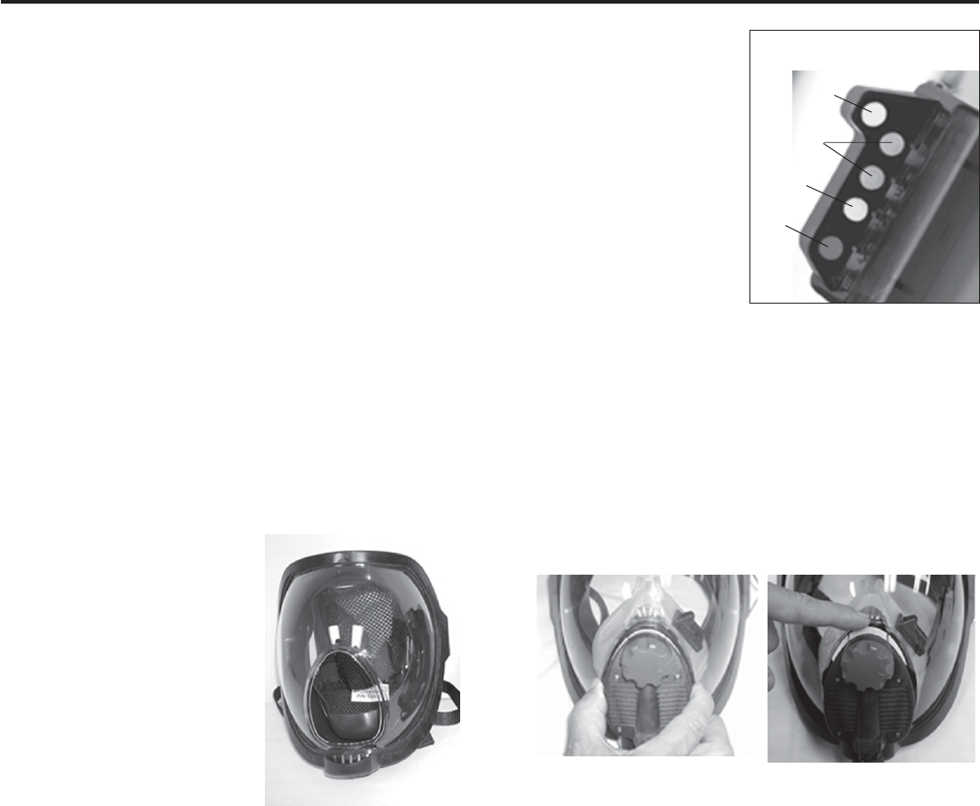
1.1 FACEMASK
The AVON-ISI full facemask as-
sembly has a two point pull-for-
ward Nomex net harness with an
optically-corrected, double curve
high-impact polycarbonate visor.
The visor’s scratch-resistant coat-
ing conforms to NFPA standards.
The interior of the visor has a per-
manent anti-fog coating. The
facemask standard seal is high-
strength butyl blend and has a
patented blended shape which
fits the firefighter's helmet without
readjustment. A standard black
inner-mask nosecup reduces
dead-air space and CO2 buildup. The facemask has CBRN la-
bels affixed at both lower corners of the visor.
1.0 DESCRIPTION OF VIKING Z SEVEN SCBA
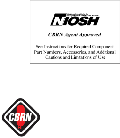
An in-mask HUD is mount-
ed to the inner-mask nose-
cup. The mask display in-
cludes five LEDs: red = ¼
full, yellow = ½ full, 1st
green = ¾ full, 2nd green =
full, and the last elevated
yellow = low battery indica-
tor. The HUD indicates re-
maining cylinder pressure
and provides the primary
end-of-service time alarm.
The HUD can also provide
additional status indicators
depending upon the op-
tions ordered.
1.2 AIRSWITCH
®
REGULATOR
The patented AirSwitch second stage regulator is incorporat-
ed into the facemask and combines the demand and exhala-
tion valves to greatly reduce breathing resistance. This also
allows for a longer duration of cylinder use. A speech dia-
phragm provides excellent clarity and voice reproduction
while incorporating the exhalation valve.
The AirSwitch features a fresh air mode which allows users
to go from cylinder air to outside air by depressing the two
control slide tabs inward and then raising the slide upwards
fully. Push down for cylinder or supplied air. The AirSwitch
should stay open prior to donning and doffing of the VIKING
SCBA. The AirSwitch is made of high performance engi-
neered plastics and incorporates a true manual bypass con-
trol for emergency use.
S- SPECIAL OR CRITICAL USER’S INSTRUCTIONS,
CONTINUED
• This approval applies only when the device is supplied with
respirable breathing air through 6 to 300 feet of hose at air
pressures between 80 to 120 pounds per square inch gauge or
from self contained air supply.
Note: Viking CBRN SCBAs are not approved for supplied air use
in confirmed or potential CBRN environments.
• If the supplied air fails, open the cylinder valve, unplug supply air
and proceed to fresh air immediately.
• Use adequate skin protection when worn in gases and vapors
that poison by absorption (example: hydrocyanic-acid gas).
yellow
(low battery)
green
yellow
red
DOWN FOR SUPPLIED AIRUP FOR AMBIENT AIR
COPYRIGHT 2007 AVON - ISI
4
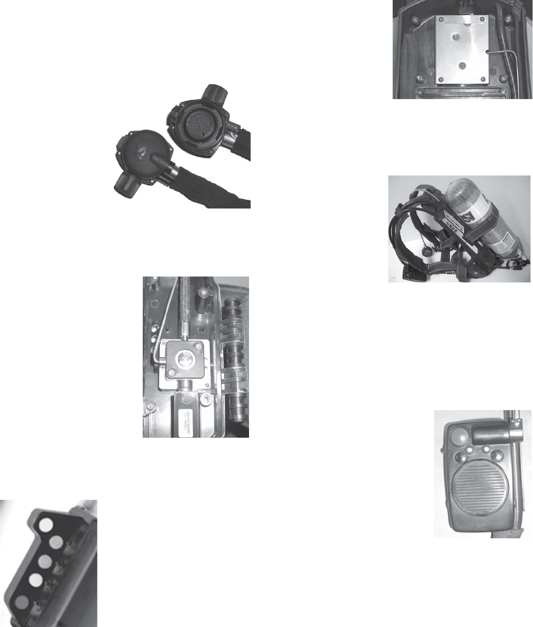
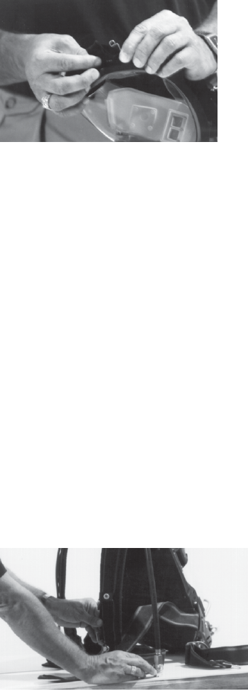
1.3 REMOVABLE DEMAND VALVE (RDV) REGULATOR
The Viking RDV regulator is a mask mounted second stage
regulator with a 1/8th turn positive locking mechanism, which
secures into the facemask. The RDV facemask incorporates a
speech diaphragm that provides excellent speech clarity even
under heavy breathing. The standard HUD is still inside the
facemask with the
microphone. Docking
the RDV on the
facemask also aligns
the electronic
connection in one
simple step. After
removing the RDV from
the facemask, it should
be stored in the
docking station on the
waistbelt strap to keep
free of dirt and debris.
1.4 FIRST STAGE PRESSURE REDUCER
Air leaves the cylinder, passes through a sintered bronze filter
in the handwheel elbow assembly, and then continues on
through a high pressure flexible
hose to the first-stage pressure
reducer where it is reduced to ap-
proximately 125 psi. The reducer
is a simple piston type that re-
quires no adjustment and incorpo-
rates an automatic, self-seating
pressure relief valve to protect the
low-pressure components down-
stream. It is made of high quality
aluminum, and is securely mount-
ed inside the backframe assem-
bly.
1.5 END-OF-SERVICE
INDICATORS
The primary End-of-Service indi-
cator is incorporated into the HUD. The display will flash a
single red LED at 23% to 27% of rated cylinder pressure per
NIOSH requirements. The primary end-of-service alarm
meets NFPA 1981, 2007 Edition requirements.
The secondary End-of-
Service indicator is a bell
mounted inside the back-
frame which is set to acti-
vate at 23-27% of rated
cylinder pressure per
NIOSH and NFPA re-
quirements.
1.6 BACKFRAME AND HARNESS
The backframe and harness assembly utilize ergonomic de-
sign principles to produce a comfortable, low profile unit that
evenly distributes the SCBA weight between the wearer’s
hips and shoulders.
The unique double-wall
backframe of the Viking
protects major airlines,
the first stage reducer,
bell alarm and digital
components. A quick-re-
lease cylinder band fits a
wide range of cylinders
with an infinitely adjust-
able latch to ensure a
tight fitting cylinder.
The harness material is NFPA compliant, custom woven
KEVLAR®. The upper harness has very resilient foam rubber
padding for added comfort and PBI/KEVLAR cover for maxi-
mum durability and protection. There is an optional back-
frame plate that can be ordered (p/n 099038) to reinforce the
upper harness straps for departments that do heavy simula-
tion training of fire fighter rescue operations. A lower lumbar
pad is standard for added comfort and support.
1.7 CONTROL CONSOLE
The control console and PASS
assembly communicate with each
other through a wireless network.
The network uses a discreet fre-
quency that eliminates noise and
resistance to other radio frequen-
cies. This wireless network joins
the Control Console and PASS
assembly together, allowing for
constant data to be exchanged.
There are two motion sensors on
the Z SEVEN, one in the Control
Console and one in the PASS assembly inside the back-
frame. When one assembly detects motion, the PASS will re-
set for 25 seconds.
Note: Only Duracell MN 1500 or Energizer E91
1.5 volt AA batteries are to be used with the battery
packs. Be sure to place batteries in the direction as
indicated on the battery compartment in order to pro-
long battery and fuse life.
red end of service
alarm
COPYRIGHT 2007 AVON - ISI 5
1.7.1 SERVICING CYLINDER VALVE
After each use, and prior to recharging, the cylinder valve
must be inspected for damage. If a new valve is replacing a
valve that was damaged in use, it will be necessary to hy-
drotest the cylinder before installing the new valve.
Note: Any maintenance on the valve that requires
disassembly should be conducted by an AVON-ISI
Authorized personnel or an AVON-ISI technician who
is well trained in the hazards of high pressure
equipment. Never attempt to remove the valve from
the cylinder while there is any pressure in the
cylinder. Open the valve completely to be sure it is
empty. If the gauge shows pressure but you think the
cylinder is empty, contact the AVON-ISI factory for
advice by calling 888-474-7233.
Note: Prior to revalving a cylinder, you must perform the fol-
lowing inspection:
• Remove o-ring from sealing threads on cylinder valve.
• Clean threads to remove any lubricant.
• Inspect the cylinder threads, ensuring the threads are not
distorted or cracked.
• Inspect the valve threads, ensuring the threads are not
distorted or cracked.
1.8 CYLINDER AND VALVE ASSEMBLY
A range of cylinder types and capacities are available on the
VIKING 2216 psi and 4500 psi models. (Please see the table
in Section 1.10 for specifics.)
The cylinder valve is of aluminum construction with a perma-
nent teflon coating. The valve outlet is a standard CGA-346
fitting on 2216 psi cylinders, and a standard CGA-347 fitting
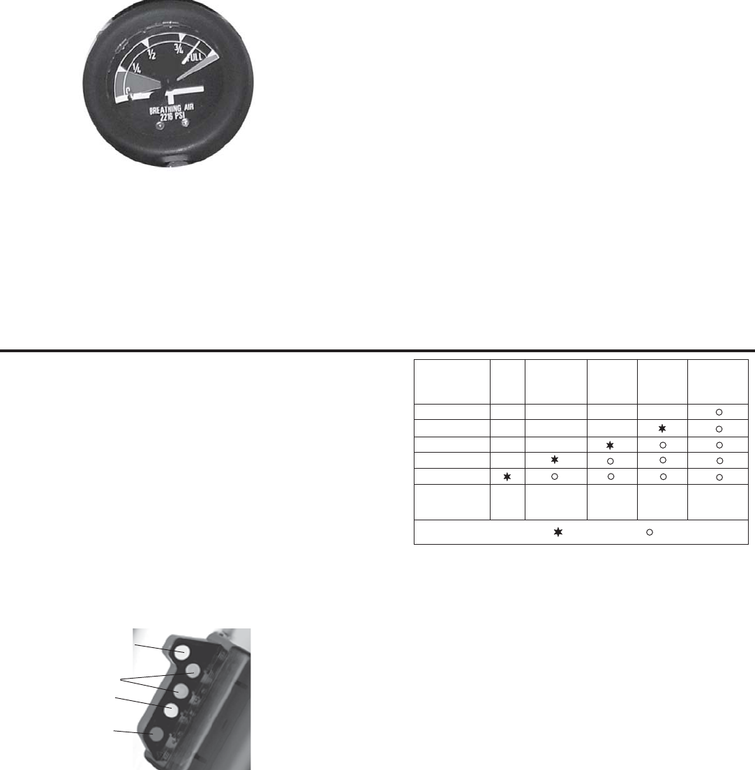
on 4500 psi cylinders. Each valve has a dual-reading pres-
sure gauge. Valve protection is provided by an elastomeric
bumper. See section 2.3.2 for inspection prior to use.
The valve can be used with AVON- ISI cylinder assemblies
between 23 cubic feet and 87 cubic feel. The cylinder valve
has a burst disc type safety device to protect the cylinder
from over pressurization.
The cylinders and valve are matched according to pressure.
The maximum pressure on the gauge built into the cylinder
valve should match the pressure rating on the cylinder. A
2216 psi valve will not fit into a 4500 psi cylinder and vice
versa. For easy recognition AVON- ISI has made 4500 psi
handwheels red and a 2216 psi handwheel black. (Exception:
all Viking ST models will have black handwheels no matter
what the pressure rating of the cylinder.)
The cylinder valve has two sets of male threads - one will
screw into the cylinder and the other is used to attach to the
pneumatics of the SCBA. The latter threads are referred to as
CGA (Compressed Gas Association) threads. It is important
to protect the CGA threads so that the pneumatics will always
screw onto them without doing damage to the handwheel on
the pneumatics.
If any threads are distorted or cracked, the parts should be
tagged “Out of Service” and be condemned.
HANDLING PRECAUTIONS:
NEVER LIFT OR CARRY UNIT BY THE HIGH PRES-
SURE HOSES. IF A HIGH PRESSURE HOSE BE-
COMES KINKED OR OTHERWISE DAMAGED, IT
SHOULD BE REPLACED. CHECK FOR DAMAGE
NEXT TO THE METAL ENDS OF THE HOSE.
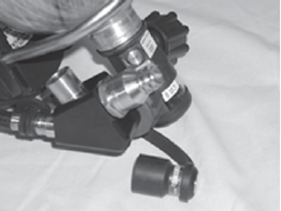
1.9 RAPID INTERVENTION CREW (RIC) FITTING
Every Viking Z SEVEN has a RIC fitting attached near the
handwheel that allows a downed fire fighter to have their cyl-
inder charged from an outside source. NFPA 1981, 2007 Edi-
tion requires this fitting on all SCBA’s manufactured for fire
fighters. The RIC fitting is compatible with other manufactur-
ers and is intended as an emergency refill only. The RIC fit-
ting will not work as a transfill system between two SCBA’s.
There is a dust cap cover for the fitting to prevent debris on
the fitting. See section 4.7 for detailed working instructions.

COPYRIGHT 2007 AVON - ISI
6
1.10 VIKING CYLINDER TABLE
aAll Carbon Cylinders have 5 year hydrostatic intervals.
024.037.00 2216 Aluminum 1287 liters, 45 cu. ft. 30 min. 20.5 lbs. 6.9 in. 5 years Life
024.035.00 2216 Hoop-Wrapped Glass 1301 liters, 45.5 cu. ft. 30 min. 16.0 lbs. 6.9 in. 3 years 15 years
124001 2216 Full Wrapped Carbon 1301 liters, 45 cu. ft. 30 min. 10.4 lbs. 6.8 in. 5 yearsa15 years
024.098.00 4500 Hoop-Wrapped Glass 1287 liters, 45 cu. ft. 30 min 15.9 lbs. 5.5 in. 3 years 15 years
124002 4500 Full Wrapped Carbon 1287 liters, 45 cu. ft. 30 min. 11.0 lbs. 5.4 in. 5 yearsa15 years
124003 4500 Full Wrapped Carbon 1887 liters, 66 cu. ft. 45 min. 14.8 lbs. 6.8 in. 5 yearsa15 years
124004 4500 Full Wrapped Carbon 2516 liters, 88 cu. ft. 60 min. 19.2 lbs. 7.1 in. 5 yearsa15 years
124027 4500 Hoop-Wrapped Glass 1287 liters, 45 cu. ft. 30 min 15.9 lbs. 4.0 in. 3 years 15 years
124028 4500 Full Wrapped Carbon 1287 liters, 45 cu. ft. 30 min 11.0 lbs. 5.4 in. 5 yearsa15 years
124029 4500 Full Wrapped Carbon 1887 liters, 66 cu. ft. 45 min 14.8 lbs. 56.8 in. 5 yearsa15 years
124030 4500 Full Wrapped Carbon 2516 liters, 88 cu. ft. 60 min 19.2 lbs. 7.1 in. 5 yearsa15 years
024.066.00 4500 Full Wrapped Glass 1282 liters, 45.3 cu. ft. 30 min 14.1 lbs. 5.6 in. 3 years 15 years
024.085.00 4500 Full Wrapped Glass 1854 liters, 65.5 cu. ft. 45 min 18.9 lbs. 6.8 in. 3 years 15 years
Part Pressure Material Free Air Capacity NIOSH Rated Cylinder & Cylinder Hydrostatic Cylinder
Number PSIG Duration @ Valve Charged Diameter Interval Lifeb
2.1 UNPACKING
Open the storage case or shipping container. Observe the
relative position and placement of the various components for
future repacking. Remove the SCBA from the container and
place on a clean dry surface. Remove the facemask from
protective bag. Remove battery pack from protective bag. In-
stall battery pack into backframe according to battery pack in-
stallation instruction in section 8.3. Install control console bat-
teries according to installation instructions in section 8.3.
2.2 INVENTORY AND EXAMINATION
Examine unit for physical condition and appearance of all
components. Be sure the following major components are in-
cluded:
•Facemask and regulator assembly in storage bag
•Backframe and harness assembly
•Cylinder and valve assembly
•Batteries for control console
•Backframe battery pack with batteries if equipped with
PASS
•Options ordered with unit: buddy breather, airline, etc.
2.3 ROUTINE CHECKS AND INSPECTIONS
The following procedure shall be used for new incoming units
and daily inspections of the apparatus. An SCBA not routine-
ly used, but kept for emergency use, shall be inspected at
least monthly. All other breathing apparatus shall additionally
be inspected after each use.
NOTE: BLACK KELAR CYLINDER BAGS (PART #: 138082, 138091, 138092, 138093) ARE OPTIONAL COSMETIC COVERS THAT MAY BE PURCHASED TO COVER CYLINDERS.
2.0 ROUTINE CHECKS
WARNING
THE APPARATUS MUST NOT BE USED UNTIL THE
FOLLOWING TESTS HAVE BEEN SUCCESSFULLY
COMPLETED. ANY DISCREPANCY NOTED DURING
THE PRE-USE CHECK AND INSPECTION SHALL BE
CORRECTED ONLY BY AUTHORIZED PERSONNEL
PRIOR TO USE OF THE APPARATUS.
2.3.1 Visually inspect complete apparatus for worn or
aged parts and damaged components.
2.3.2 Basic cylinder inspection shall include:
A. Inspect gauge for damage.
B. Inspect cylinder for mechanical damage (cracks,
dents, gouges) or signs of heat or chemical damage.
(Refer to CGA C-6.2 Guideline for Visual Inspection
and Requalification of Fiber Reinforced High
Pressure Cylinders for all wrapped cylinders.)
C. Check that hydrostatic test date on cylinder is
current.
D. Check that cylinder valve threads are not
damaged.
E. Check that the valve body is not bent.
F. Check that the burst disc outlet is clean and free
of debris.
G. If any item listed above is noted, depressurize
cylinder to a slight positive pressure, tag, and take
out of service.
COPYRIGHT 2007 AVON - ISI 7
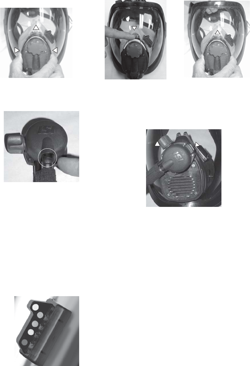
2.3.3 AirSwitch:
Open control
slide on
AirSwitch by
pressing inward
and upward on
two protruding
tabs on both
sides of control
slide. Also make
sure the red
bypass knob is
in the closed position (i.e. fully turned clockwise
when looking at front of mask). See paragraph
3.1.9 for connection instructions.
RDV: Push inward
on the RDV First
Breath Button. Also,
make sure the red
bypass knob is in
the closed position.
2.3.4 Ensure high pres-
sure handwheel is tightened completely prior to
opening the cylinder valve. Open the cylinder valve
slowly by turning the cylinder valve knob counter-
clockwise to the fully open position. The console
should emit an audible chirp. The bell should acti-
vate and then shut off. There should be no air flow
from the facemask. If air is flowing, check that the
bypass valve is closed.
WARNING
ENSURE THAT ONLY A 2216 PSI CYLINDER IS
USED WITH LOW PRESSURE PNEUMATICS AND A
4500 PSI CYLINDER IS USED WITH HIGH PRES-
SURE PNEUMATICS.
2.3.5 CHECK CYLINDER PRESSURE: The heads-up
display will have four lights "on" when the cylinder
is full. When the cylinder
pressure is between 3/4
and 7/8, the top green
light will be flashing and
the analog pressure
gauge readout should
read at or above the 7/8th
level. If the top green
light is "off" or below the
specified levels, refill the
cylinder or replace with a
fully charged cylinder.
2.3.6 AirSwitch: While holding the facemask, push
down on the top of the control slide to close the Air-
Switch and QUICKLY push back to the UP position.
First 4 lights of
the HUD shows
cylinder pressure
bypass latch
There should be a rush of air when the slide is
pushed down, and the air flow should stop when the
slide is in the UP position.
RDV: RDV can be attached from either left or right
orientation. Dock RDV into facemask by turning the
RDV until the bypass knob is facing either the 1
o'clock or 4 o'clock position depending on user com-
fort. Place RDV into mask and rotate till latch is in the
12 o'clock position (1/8th turn to lock). Inhale to ac-
tive airflow. Attempt to rotate RDV to ensure RDV is
locked.
2.3.7 Open bypass and check for constant air flow. Close
bypass.
2.3.8 BATTERY CHECK: If the batteries are low, the top
yellow LED on the HUD will be "ON". In addition, if
equipped with PASS, the control console will make a
beeping noise every 15 seconds to alert the status of
the PASS battery and the console LED will be red.
See paragraph 8.3 to replace the batteries.
2.3.9 LEAK TEST: For the Airswitch, ensure the control
slide is in the up position and the bypass is closed.
For the RDV, push inward on the first breath button to
stop airflow and make sure bypass is closed. Using a
full cylinder, open the cylinder valve slowly until the
pneumatics are completely pressurized. Allow pres-
sure to stabilize for 30 seconds. Close cylinder valve
for one minute. Open cylinder valve slowly and ob-
serve the analog gauge needle movement. If the nee-
dle on the gauge moves more than 1/8th inch, the Vi-
king should be removed from service and tagged for
repair.
COPYRIGHT 2007 AVON - ISI
8
TECHNICIAN MAINTENANCE
AT LEAST ONCE PER YEAR, THE ENTIRE SCBA
SHOULD BE PLACED OUT OF SERVICE AND
TAGGED FOR ANNUAL FLOW TESTING BY AN
AVON-ISI AUTHORIZED TRAINED TECHNICIAN.
2.4 SCBA RETIREMENT
Over the course of time, the Viking SCBA needs to be evalu-
ated on its' overall condition. Inspect the Viking's harness as-
sembly for frayed, deteriorating harness', stress cracks in the
backframe and in general, it's overall condition. Another con-
sideration is passing the annual dynamic flow testing require-
ments. Over time components may need to be replaced or
consideration must be made to retire the SCBA.
Fire Department that plans on retiring their SCBA's or no
longer meet the current NFPA requirements, should review
NFPA 1852, 2002 Edition, section 4.3 and 4.6 for guidelines
on retiring an SCBA.
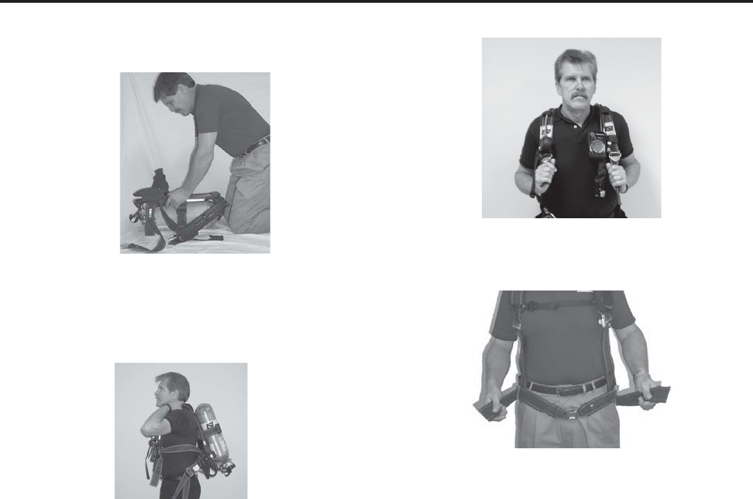
3.1 DONNING PROCEDURES
3.1.1 Position the VIKING SCBA on the ground with the
cylinder valve facing away from the wearer.
3.1.2 Spread the shoulder straps and fold open the side
arms. Ensure all strap assemblies (side and waist)
are fully extended and waist belt buckle assembly is
not connected. Reach inside the harness assembly
and grasp the frame with both hands.
3.1.3
Swing the unit up and over the head, making sure that
the elbows extend through the loops formed by the
shoulder straps. Allow the unit to slide down the back.
3.1.4 Pull directly down on the shoulder straps to adjust
position of unit on back, attach chest strap.
3.1.5 Connect the waistbelt buckle and adjust waistbelt to
a comfortable snug fit by pulling simultaneously on both left
and right adjustment straps. Tuck the excess waistbelt and
shoulder strap pull-downs inside the waistbelt.
2.3.10 LOW PRESSURE ALARM TEST: Gradually reduce
the system pressure by slightly opening the bypass
valve. Verify that the bell sounds and the mask dis-
play blinks a single red LED as the needle from the
analog gauge is at the 1/4th increment.
2.3.11 Check the RIC fitting to ensure the dust cover is in
place.
IMPORTANT
COMPLETE ALL ROUTINE CHECKS AND INSPECTION
PROCEDURES OUTLINED IN SECTION 2 BEFORE START-
ING DONNING PROCEDURES, SECTION 3.
WARNING
IF ANY OF THE PREVIOUS TESTS FAIL, REMOVE
APPARATUS FROM SERVICE, TAG, AND RETURN
FOR REPAIR BY AVON-ISI AUTHORIZED
PERSONNEL.
3.0 DONNING PROCEDURES AND SAFETY CHECKS
COPYRIGHT 2007 AVON - ISI 9
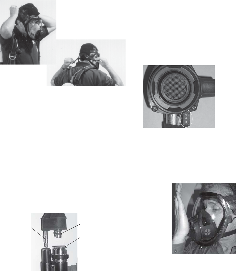
3.1.8 To connect the facemask to the Viking unit, connect
electronics plug partially into socket, then connect
facemask plug into connector. Press firmly in to lock
both fittings into each socket. A click should be
heard when it is locked in place securely.
Note: When connecting the facemask hose to the
connector, make sure both hoses are connected and
the socket sleeve has moved forward. If socket
sleeve has moved forward without the facemask
hose connected, air will leak out of the socket
connector.
For the RDV mask, the HUD electronic connection
is made when the RDV is docked into the facemask.
Prior to donning the RDV, ensure that the contact
pins are free of any debris.
Note: In an IDLH atmosphere, such as a CBRN response,
ensure that the facemask is connected to the
pneumatic connection prior to entering the
hazardous area to prevent contamination.
Note: Prior to docking the RDV, the user can perform a
negative pressure check on the AVON-ISI mask.
Place your hand to block off the RDV opening in the
facemask. Inhale slightly and hold your breath.
Facemask should move inward slightly and stay in
that position unit user exhales. It may be difficult to
perform this with a gloved hand. Annual fit testing is
required to ensure proper fit.
Note: It is not necessary to perform a negative pressure
check on the AirSwitch because it is designed as a
positive pressure facemask. AVON-ISI recommends
annual fit testing to ensure a proper fitting facemask.
Pull straps
FORWARD
on net
harness
3.1.6 Don AirSwitch mask: With the control slide in the
"up" position and with one hand on the head harness
straps, put chin into facemask first and then pull
harness straps over head. Position facemask so that
chin fits snugly into chin cup and pull the two
harness adjusters forward evenly. Pull net toward
base of the skull to ensure it is seated fully.
Don RDV mask: Do not dock the RDV regulator until
after the mask is donned. With one hand on the
head harness straps, place chin into facemask and
then pull harness strap over users head. Position
facemask so the chin fits securely in the chin cup
and pull the two harness adjusters forward evenly.
Pull net toward base of the skull to ensure it is
seated fully.
IMPORTANT
DO NOT OVERTIGHTEN THE FACEMASK. DOING SO MAY
CAUSE DISCOMFORT OR FACEMASK DEFORMATION
AND LEAKAGE.
3.1.7 Ensure the AirSwitch control slide is in the UP
(open) position, and the bypass valve is closed.
WARNING
BE SURE TO ALIGN THE CONNECTOR AND FACE-
MASK PLUG CORRECTLY AS SHOWN ABOVE.
DAMAGE WILL RESULT TO THE PIN IN THE CON-
NECTOR IF THE ELECTRONICS PLUG IS MISTAK-
ENLY PUSHED INTO IT.
facemask plug
electronics
plug
connector
contact
pins
COPYRIGHT 2007 AVON - ISI
10
AVON-ISI offers facemasks in three different sizes to
ensure a proper fit. Refer to the AVON-ISI Instruction
Sheet for the Viking Facemask (p/n 084022, a/w
A49022) for proper sizing of the facemask.
3.1.9 Ensure high pressure handwheel is tightened com-
pletely prior to opening the cylinder valve. Open the cylinder
valve slowly by turning the cylinder valve counterclockwise to
the fully OPEN position. The control console should emit an
audible chirp.If equipped with PASS, the PASS should emit
an audible chirp. The bell should activate and then shut off
and the HUD should be "on", showing quarter increments of
cylinder pressure. The yellow "low battery" LED will light and
then turn off.
Note: On the RDV, the HUD will activate AFTER the RDV
is docked into the facemask.
3.1.10 AirSwitch: To activate cylinder airflow push down
on the control slide.
RDV: To activate air flow, remove RDV from docking
station on waistbelt and dock the RDV on the face-
mask by orientating the bypass valve in the 1 o'clock
or 4 o'clock position, push RDV into the front open-
ing, and rotate 1/8th turn. Inhale to activate airflow.
WARNING
IF USER IS UNABLE TO ACTIVATE THE “FIRST
BREATH” OPEN BYPASS IMMEDIATELY, REMOVE
RDV, CLOSE CYLINDER VALVE AND TAG “OUT OF
SERVICE”.
3.2 SAFETY CHECKS
WARNING
THESE SAFETY CHECKS MUST BE PERFORMED
BEFORE ENTERING A HAZARDOUS AREA. FAIL-
URE TO PERFORM THESE CHECKS MAY RESULT
IN RESPIRATORY INJURY OR DEATH.
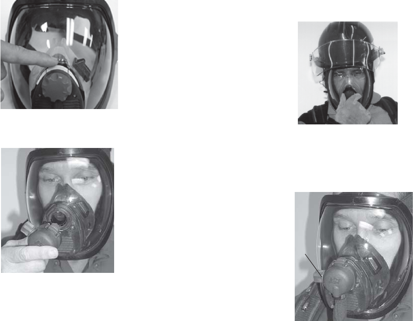
3.2.1 AirSwitch positive pressure fit check: With cylin-
der valve open, push down on the control slide to activate air
supply and breathe normally.
RDV positive pressure fit check: With the mask
donned and the RDV docked, inhale to activate air-
flow.
Insert two fingers between the facemask and face. Gently lift
the facemask seal away from the face and ensure a good
outward flow of air, showing that the facemask pressure is
positive. Reseal facemask and stop breathing for 3 seconds.
There should be no sound of air leaking from the regulator,
and there should be no airflow sensed in the eye region of
the mask.
3.2.2 ALARM CHECK: Close the cylinder valve and con-
tinue to breathe normally. As the air reaches the ¼ full level
the red LED light should flash rapidly and all other lights
should be out. The secondary bell alarm should also activate.
3.2.3 Open cylinder valve. Take two to three deep breaths
to ensure you are getting adequate air into the facemask. The
facemask should not move towards your face.
3.2.4 AIRSWITCH BYPASS CHECK: The red bypass
knob is located in the center of the AirSwitch. Turn the by-
pass knob clockwise as viewed inside the mask (the direction
shown by the knob arrow) to open the bypass valve. A con-
stant flow of air should pass into the facemask. Turn the knob
in the opposite direction to turn the bypass valve off.
RDV BYPASS CHECK: The bypass knob on the
RDV is located on the right side (from the wearer
view). To open, rotate knob towards the user fully. A
constant flow of air should pass into the facemask.
Turn the knob in the opposite direction to close.
3.2.5 RECHECK CYLINDER PRESSURE: Check the
heads-up display. Four lights should be "on". The
top green light may be flashing, indicating at least 7/
8th full.
Verify the analog gauge is at or above the 7/8th level.
bypass
COPYRIGHT 2007 AVON - ISI 11
IMPORTANT
THE USER SHOULD BE TRAINED ON HOW TO HANDLE A
POSSIBLE EMERGENCY BEFORE ENTERING A HAZARD-
OUS AREA.
The Viking SCBA can be equipped with a variety of fully-inte-
grated solid state features that offer safety and communica-
tion advantages for the user. Review section 9 for detailed in-
structions of available options.
4.1 READING THE HEADS-UP DISPLAY (HUD)
4.1.1 The HUD includes five LED lights: two green, two
yellow and one red. Each of the 4 LEDs in a row represents a
quarter increment of the rated service pressure. As cylinder
pressure decreases, the LEDs change status. At full rated
service pressure, all four LEDs are on. As cylinder pressure
drops below full, the top green LED begins blinking. At ¾
rated service pressure, the top green LED turns off and the
next green LED begins blinking. At ½ rated service pressure,
the second green LED turns off and the yellow LED begins
blinking. At ¼ rated service pressure, the yellow LED turns
off, and the red LED blinks at a fast rate. The top offset
yellow light is a low battery indicator. Refer to the following
table for more information regarding mask pressure display
interpretation.
3.2.6 BATTERY CHECK: The top yellow LED will be "ON"
when the control console batteries are low. If the
pass batteries are low, displays red LED on console
and the pass alarm will chirp every 15 seconds. The
LED on the console will be red. If the SCBA shows a
low battery warning, replace batteries in accordance
with section 8.3.
3.2.7 VAS CHECK
3.2.7.1 Turn SCBA on by either opening cylinder valve or by
manually depressing on buttons.
3.2.7.2 Hold mask up to face and speak into mask.
3.2.7.3 Listen to speech emanating from VAS speaker and
ensure its intelligibility and function.
WARNINGS
IF ANY OF THE ABOVE CHECKS FAIL, DO NOT
PROCEED. REMOVE THE APPARATUS FROM SER-
VICE, TAG, AND RETURN FOR REPAIR BY AVON-
ISI AUTHORIZED PERSONNEL.
USE OF THE BYPASS IN NON-EMERGENCY SITUA-
TIONS WILL SUBSTANTIALLY REDUCE DURATION
OF THE APPARATUS.
THE BYPASS WILL NOT FUNCTION IF THE CYLIN-
DER IS OUT OF AIR.
4.0 DURING USE
Remaining
Cylinder
Pressure
Full
Full → 3/4
3/4 → 1/2
1/2 → 1/4
Below 1/4
Low battery:
console
RED
•
•
•
•
YEL-
LOW
•
•
•
GREEN
•
•
•
GREEN YEL-
LOW
• = On = Blinking = Off
•
4.2 NORMAL USE
4.2.1 Monitor cylinder pressure for remaining air supply
using the HUD. Cylinder pressure can also be moni-
tored with the analog pressure gauge. Refer to chart
in paragraph 4.1.1 for the LED light sequence.
4.2.2 The end-of-service-time alarms (mask display and
bell) activate when there is approximately 25% of the
full air supply remaining. Egress when alarms acti-
vate. WARNING: 25% OF A FULL CYLINDER MAY
BE INSUFFICIENT IN SOME CIRCUMSTANCES TO
SAFELY EXIT FROM AN IDLH ATMOSPHERE. One
example would be a long-distance ingress through a
continuous IDLH atmosphere. In such situations, be-
gin egress prior to activation of the end-of-service-
time indicator.
4.3 CBRN SPECIFIC ACTIONS
Hazardous materials, such as CBRN agents, may
not present immediate effects from exposure, but
can result in delayed impairment, illness, or death.
Use the AVON-ISI Viking with CBRN agent approval
in conjunction with personal protective ensembles
that provide appropriate levels of protection against
dermal hazards. Refer to page 2 of this manual,
yellow
yellow (B)
(low battery)
green
red
COPYRIGHT 2007 AVON - ISI
12
Cautions and Limitations for CBRN Protection Ap-
proval.
4.4 INSTRUCTIONS FOR CHANGING CYLINDERS
4.4.1 Make sure cylinder valve is closed and all air is re-
leased from the pneumatic system.
4.4.2 Pull outward on the upper portion of the locking
latch to release tension.
4.4.3 Disconnect handwheel from cylinder valve and re-
move cylinder by sliding cylinder upward through
cylinder band.
4.4.4 Insert new full cylinder by sliding down through cyl-
inder band until cylinder rests against bottom retain-
er. Connect handwheel to cylinder valve and posi-
tion cylinder.
4.4.5 Close the locking latch.
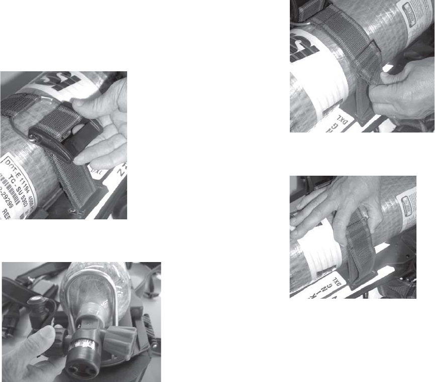
4.5 CYLINDER BAND ADJUSTMENT
4.5.1 Pull outward on the upper portion of the locking
latch to release tension.
4.5.2 To loosen the cylinder band, grab the inner cylinder-
band strap and pull out/away from the adjustment
latch.
To tighten the cylinder band, grab the outer cylinder
band trap and pull up/away from the adjustment
latch. Slide the slack across the inner strap.
4.5.3 Further adjust cylinder band length until tight. Make
sure that the locking latch is in the open position.
Slide the slack across the lower strap.
4.5.4 Close the locking latch.
Note: Over tightening latch can break the latch. Cylinder
band should hold cylinder firmly.
4.6 EMERGENCY EGRESS INDICATORS
If any of the following situations occur, egress immediately:
A. Exposure to flashover
B. Exposure to high temperature
C. Harness failure
D. Chattering or unusual noises from SCBA
E. Submersion in water (Note: In this situation the VI-
KING will continue to supply air on demand to a
depth of at least 3 meters.)
F. SCBA subjected to high impact such as a fall
G. Air flow decreases such that the facemask moves in-
ward toward the face during inhalation (Note: In this
situation, open bypass to provide extra, constant
flow.)
H. Air flows constantly at a high rate (Note: In this situa-
tion, adjust the flow rate by slowly closing the cylin-
der valve until a comfortable flow rate is established.
The flow rate should match the bypass flow rate dur-
ing normal operation.)
COPYRIGHT 2007 AVON - ISI 13
II. Digital pressure gauge, mask pressure display, or
other digital options cease to function properly.
J. End-of-service indicators activate.
K. Chemical agent egress indicators:
1. Dizziness
2. Partial loss of vision
3. Shortness of breath
4. Restricted breathing
5. Localized pain
6. Redness of skin
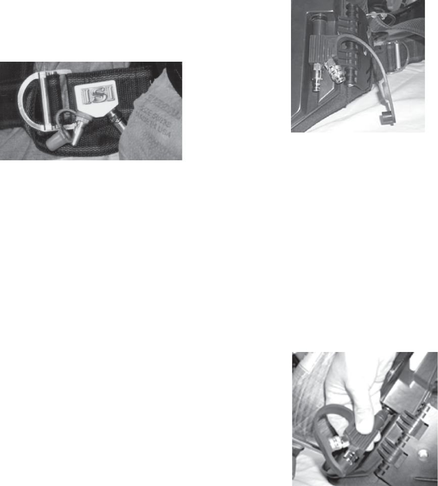
4.7 RIC FITTING PROCEDURES
The RIC fitting is designed as an emergency refill only and
has specific uses and functions per NFPA 1981, 2007
Edition. The system can only be used to fill approved SCBA
cylinders. The RIC fitting has an internal balanced piston
that prevents over pressurization of a cylinder. A check valve
prevents fire fighters from transfilling SCBA’s, or any other
unapproved use on AVON-ISI products. Users will be able to
have a 4500 psi cylinder as a supplied air system and
connect to a 2216 psi SCBA RIC connector. Air will stop
flowing automatically from the high-pressure cylinder when
the correct pressure (2216 or 4500) is achieved.
To recharge a cylinder on a downed fire fighter, an approved
charging hose must be used. The AVON-ISI Rescuer uses
the following approved hoses: a 3 foot RIC Charging Hose
(p/n 162051), a 6 foot RIC Charging Hose (p/n 162052), or a
10 foot RIC Charging Hose (p/n 162053) for filling the
cylinder in IDLH atmospheres.
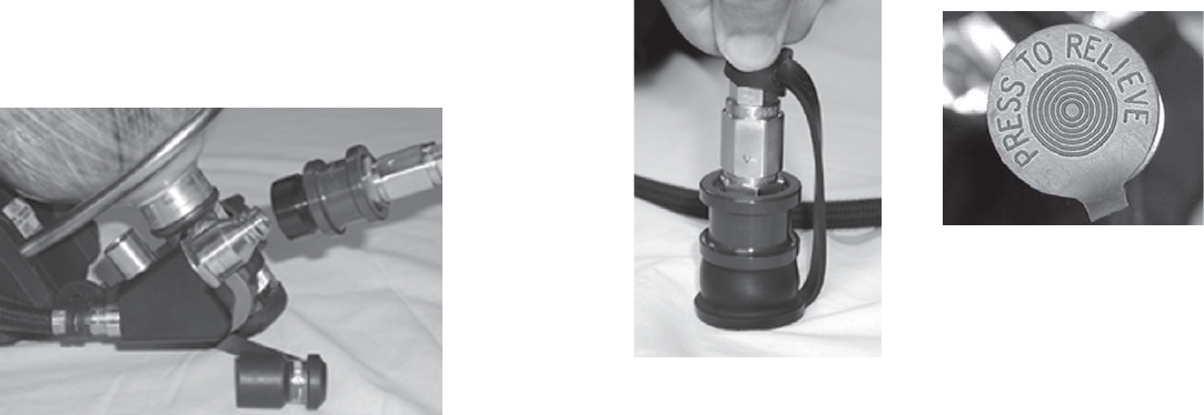
4.7.1 Open cylinder valve of supplied air and remove the
dust cap from the RIC charging hose. Inspect the
fire fighters cylinder for damage and ensure that the
cylinder valve is fully opened.
WARNING
CYLINDERS THAT ARE DAMAGED MAY SUDDEN-CYLINDERS THAT ARE DAMAGED MAY SUDDEN-
CYLINDERS THAT ARE DAMAGED MAY SUDDEN-CYLINDERS THAT ARE DAMAGED MAY SUDDEN-
CYLINDERS THAT ARE DAMAGED MAY SUDDEN-
LY RUPTURE IF CHARGED.LY RUPTURE IF CHARGED.
LY RUPTURE IF CHARGED.LY RUPTURE IF CHARGED.
LY RUPTURE IF CHARGED.
4.7.2 Remove dust cap from the RIC fitting on the SCBA
and attach the RIC charging hose to it. Listen for
leaks on the SCBA that is being filled. Recharging
will take between 2-4 minutes, depending on the
cylinder duration and pressure. When the pres-
sures equalize, unplug the charging hose from the
SCBA and replace dust covers and exit. During a pro-
longed rescue, users can leave the supplied air cylin-
der plugged into the downed fire fighter’s SCBA, add-
ing additional duration to the cylinder.
Note: If any time during charging, a leak is detected; dis-
continue charging and exit IDLH atmosphere immedi-
ately.
Note: In a non-emergency situation, cylinders shall not be
refilled through the RIC.
4.7.3 Once clear of an IDLH atmosphere, close the cylinder
valve on the RIC charging hose. Ensure there is no
debris in the dust cap prior to pushing on the dust
cap. The bottom of the dust cap reads "press to re-
lieve". With dust cap in place, push down on dust cap
on a hard surface to bleed pressure.
4.7.4 Top off cylinder attached to charging hose before
next use to ensure proper service time.
IMPORTANT
DO NOT REMOVE ANY EQUIPMENT UNTIL YOU ARE
CLEAR OF AN IDLH ATMOSPHERE.
bottom of RIC
charging hose
COPYRIGHT 2007 AVON - ISI
14
5.1 DOFFING
5.1.1 AirSwitch: Push the control slide UP on the Air-
Switch.
5.1.2 RDV: Push first breath button inward to stop airflow.
Push locking latch outward and rotate 1/8th turn to
remove RDV.
RDV: Dock on RDV docking station on waistbelt.
5.1.3 Loosen head harness straps fully and remove face-
mask.
5.1.4 Close the cylinder valve by turning it fully clockwise.
5.1.5 Release air pressure in the system by opening the
bypass until the air flow stops, then closing it.
5.1.6 Turn off all the electronics on the Z SEVEN model by
simultaneously depressing the buttons on both side
of the control console.
5.1.7 Place facemask on the shoulder harness clip.
5.1.8 Unfasten the waistbelt and loosen shoulder straps.
Extend shoulder straps and waistbelt fully. Unhook
chest strap.
5.1.9 Remove the apparatus.
WARNING
DURING COLD WEATHER OPERATIONS, THE AIR-
SWITCH REGULATOR SHOULD BE STORED IN THE
CLOSED POSITION (CONTROL SLIDE DOWN) TO
PREVENT ICE BUILDUP INSIDE THE REGULATOR.
THIS PRACTICE IS NECESSARY AS ICE MAY IN-
TERFERE WITH THE SEALS OF THE AIRSWITCH
REGULATOR WHILE IN USE.
5.1.10 Remove the cylinder and tag it for refilling. See Sec-
tion 8.2 for instructions.
5.1.11 Do not store or place apparatus in ready position un-
til after performing “After Use Cleaning” Section 6.
WARNING
SCBA USED IN A HAZMAT OR CBRN ENVIRON-
MENTS MUST GO THROUGH DECONTAMINATION
PROCEDURES. IF THE SCBA IS CONTAMINATED
WITH CBRN AGENTS, DISPOSE OF THE SCBA AF-
TER DECONTAMINATION, IN ACCORDANCE WITH
LOCAL GOVERNMENT INSTRUCTIONS OR PROCE-
DURES.
USE IN CONJUNCTION WITH PERSONAL PROTEC-
TIVE ENSEMBLES THAT PROVIDE APPROPRIATE
LEVELS OF PROTECTION AGAINST DERMAL HAZ-
ARDS.
SOME CBRN AGENTS MAY NOT PRESENT IMMEDI-
ATE EFFECTS FROM EXPOSURE, BUT CAN RE-
SULT IN DELAYED IMPAIRMENT, ILLNESS, OR
DEATH. DIRECT CONTACT WITH CBRN AGENTS
REQUIRES PROPER HANDLING OF THE SCBA AF-
TER EACH USE AND BETWEEN MULTIPLE EN-
TRIES DURING THE SAME USE. DECONTAMINA-
TION AND DISPOSAL PROCEDURES MUST BE FOL-
LOWED. IF CONTAMINATED WITH LIQUID CHEMI-
CAL WARFARE AGENTS, DISPOSE OF THE SCBA
AFTER DECONTAMINATION IN ACCORDANCE
WITH LOCAL GOVERNMENT INSTRUCTIONS OR
PROCEDURES.
THE RESPIRATOR SHOULD NOT BE USED BE-
YOND 6 HOURS AFTER INITIAL EXPOSURE TO
5.0 AFTER USE PROCEDURES

COPYRIGHT 2007 AVON - ISI 15
CHEMICAL WARFARE AGENTS TO AVOID POSSI-
BILITY OF AGENT PERMEATION.
IMPORTANT
Direct contact with CBRN agents requires proper handling of
the SCBA after each use and between multiple entries during
the same use. Decontamination and disposal procedures
must be followed. If contaminated with liquid chemical war-
fare agents, dispose of the SCBA after decontamination. For
complete instructions on decontamination procedures for a
chemical environment, please reference National Institute
Standard Technology (NIST) Special Publication 981 at
www.counterterrorism.org/pdf/nistspecialpub981.pdf.
WARNING
TO AVOID DAMAGE TO THE VISOR, DO NOT
PLACE THE FACEMASK DOWN ON ROUGH SUR-
FACES.
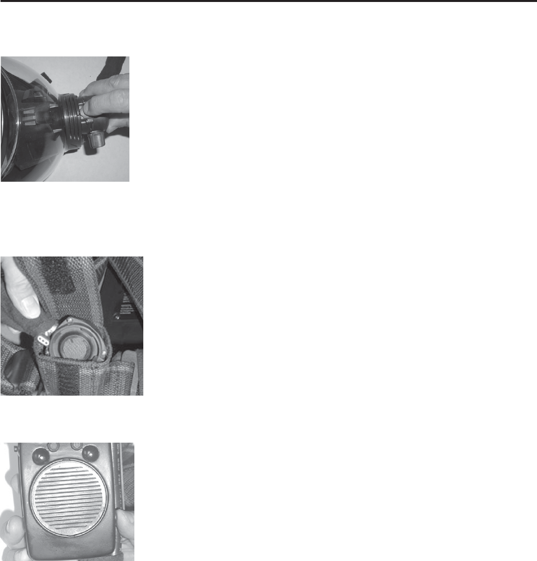
6.1 CLEANING AIRSWITCH REGULATOR AND
FACEMASK
6.1.1 Disconnect facemask hose by pushing connector
into socket and pulling back on the socket sleeve.
The electronics will unplug with the facemask hose.
Open the AirSwitch.
6.1.2 Wash the facemask in cool to warm soapy water.
Use a mild, non-detergent, dish washing soap (e.g.
Ivory). The heads-up display is completely submers-
ible.
Note: Do not immerse the hose end and electrical connec-
tor in water.
6.1.3 After rinsing, shake to remove excess water, plug
into low pressure line and close AirSwitch to allow
free-flow for a few seconds. Repeat process several
times.
NOTE: Where further cleaning due to heavy contamination
is required, clean with AVON-ISI recommended dis-
infectant/cleaner (p/n 013004) after rinsing the face-
mask. Use of other disinfectants may cause damage
to SCBA components.
6.1.4 When dry, polish the visor inside and out with a soft
clean, lint-free cloth.
6.1.5 Ensure all head harness straps are fully extended,
6.0 AFTER USE CLEANING
ready for use.
electrical
connector

COPYRIGHT 2007 AVON - ISI
16
NOTE: Cylinders that are tagged for repair should always be
stored empty with the cylinder valve closed to prevent
contamination or condensation inside the cylinder.
8.2.2 Prior to filling cylinder, follow the basic inspection
procedures outlined in paragraph 8.1.1
8.2.3 Cylinder air shall meet or exceed the standards in
NFPA 1500, paragraph 7.9.1.
8.2.4 Fill cylinder to maximum rated pressure (FULL).
Wait at least 30 minutes to allow cylinder to cool,
then add extra air to return to full at room tempera-
ture. (Note: pressure drops when cylinder tempera-
ture drops.)
8.3 BATTERY PACKS
BATTERIES FOR CONTROL CONSOLE: The
control console battery pack powers the HUD, VAS
and radio interface. The battery pack accommodates
six alkaline batteries. The low battery indicator is the
in-mask HUD offset top yellow light, displaying a solid
yellow light. The LED light on the console will be red.
BATTERIES FOR PASS: The PASS battery pack
within the backframe powers only the PASS option. It
accommodates two sets of four AA alkaline batteries.
Each set of four is independent of the other in case of a
battery failure. As battery voltage drops, each set of four
batteries switch to the highest voltage side available until
the HUD low battery indicator shows that all eight
batteries need replacing. The low battery indicator is the
in-mask HUD offset top yellow light, displaying a solid
yellow light. The control console will also emit an audible
NOTE: The Viking SCBA facemask and elastomers should be
inspected periodically for cracks, abrasions, cuts and signs
of heat or chemical damage. If detected, the unit should be
taken out of service until repaired.
8.1 MAINTENANCE INTERVALS
8.1.1 Perform annual dynamic flow test using Posichek III
with AVON-ISI software as outlined in NFPA 1852.
8.1.2 Every three years disassemble, clean and inspect o-
rings on major components.
8.2 CYLINDER FILLING PROCEDURES
8.2.1 Basic cylinder inspection shall include:
A. Inspect gauge for damage.
B. Inspect cylinder for mechanical damage (cracks,
dents, gouges) or signs of heat or chemical
damage. (Refer to CGA C-6.2 "Guideline for
Visual Inspection and Requalification of Fiber
Reinforced High Pressure Cylinders" for all
wrapped cylinders.)
C. Check that hydrostatic test date on cylinder is
current.
D. Check that cylinder valve threads are not
damaged.
E. Check that the valve body is not bent.
F. Check that the burst disc outlet is clean and free
of debris.
G. If any item listed above is noted, depressurize
cylinder to a slight positive pressure, tag, and
take out of service.
7.1 SCBA STORAGE
7.1.1 Complete routine checks and inspection procedures
outlined in Section 2.3 of this manual.
7.1.2 Ensure complete apparatus is clean and dry.
7.1.3 Ensure AirSwitch is in the UP position, and the by-
pass knob is in the CLOSED position.
7.1.4 Ensure RDV is stored in RDV docking station.
7.1.5 Ensure facemask and head harness straps are fully
extended. Unplug facemask assembly and store in
case, positioned to avoid distortion.
7.1.6 Ensure shoulder and waistbelt straps are fully ex-
tended.
7.1.7 Place the complete apparatus in the storage case or
suitable storage place so it can be easily reached for
emergency use.
7.1.8 Mounting SCBA in vehicle: When storing the SCBA
using mounting brackets, ensure that brackets are se-
cure and that no sharp objects will come in contact with
the SCBA. Ensure that the brackets do not interfere
with the backframe components.
7.1.9 Ensure control console is turned off and is clean and
dry.
7.0 SCBA STORAGE
8.0 USER MAINTENANCE
COPYRIGHT 2007 AVON - ISI 17
chirp every 12 seconds and the console LED pass
light will be red.
Note: Electronics will operate at least two hours in low
battery mode.
Battery life depends on many variables. Some fire
departments may use the Viking once every day for
six months before they have to change batteries.
Another fire department may only use the Viking
once a month. Both batteries may have to be re-
placed within six months. The difference is the
amount of power loss from using the electronic op-
tions. The Viking Z SEVEN has several options that
can increase battery consumption. The VAS draws
about 700 ma. and radio communications draws
about 250 ma. The rest of the lights that use LED’s
draw very little power. Heat and cold also affect bat-
tery life. During internal heat tests (160 ºF) and cold
tests (-25º F) battery life dropped by 50%.
WARNING
WHEN REPLACING THE AA BATTERIES, ENSURE
THAT THE BATTERIES ARE NOT INSTALLED
BACKWARDS WITHIN THE BATTERY PACK. RE-
VERSING THE POLARITY OF THE BATTERY FOR
EVEN ONE SECOND CAN CAUSE THE BATTERY
TO LEAK OVER TIME. IF A BATTERY IS IN-
STALLED BACKWARDS, DO NOT USE THIS BAT-
TERY BUT DISPOSE OF THIS BATTERY. FAILURE
TO REPLACE THIS BATTERY WILL CAUSE COR-
ROSION OVER TIME AND CAUSE A COMPLETE
BATTERY FAILURE.
Note: Only Duracell MN 1500 or Energizer E91 AA batteries are
approved for use through intrinsic safety standards for use
on the Viking SCBA.
8.3.1 CONTROL CONSOLE BATTERY PACK REMOVAL:
Remove the two screws on the back cover of the
console. Seperate the cover from the console base.
It may be necessary to carefully pry the cover off.
The batteries are in pairs of two.
8.3.2 CONTROL CONSOLE BATTERY REPLACEMENT:
Remove old batteries, observice the polarity. Install
new batteries using new alkaline MN 1500 or E 91
AA batteries. Ensure that each battery touches each
contact point. Tighten screws to secure back con-
sole cover. Do NOT over-tighten.
8.3.3 PASS BATTERY PACK INSTALLATION: Ensure
battery pack seal is in place, free from debris, and
that the “T” guard between the battery clips is in
place, protecting against shorting out the battery
fuse. Push battery pack into battery compartment
such that the clips snap over the two brass contact
pins. The control console will turn on, emit an audi-
ble chirp, and then turn off. Secure battery pack to
backframe with four Torx screws.
8.3.4 PASS BATTERY PACK REMOVAL: Completely
loosen four Torx screws which secure the battery
pack to the backframe. Begin lifting battery pack out
of the battery compartment by prying with a coin or
flat-head screwdriver under the battery pack recess.
8.3.5 PASS BATTERY REPLACEMENT: With the battery
pack removed from the backframe, remove old batteries from
battery pack and replace with new AA alkaline batteries. En-
sure that each battery is properly installed, noting polarity as
shown in battery compartment and battery compartment tray.
Ensure that each battery touches both battery pack contacts.
Ensure battery pack seal is in place, free from debris. Prior to
placing the battery pack within the backframe, ensure that the
“T” guard between the battery posts is in place, protecting
against shorting out the battery fuse. Push battery pack into
battery compartment such that the clips snap over the two
brass contact pins. The control console will turn on, emit an
audible chirp, and then turn off. Secure battery pack to back-
frame with four Torx screws.
8.4 NET HEAD HARNESS REPLACEMENT
Tools Required: Harness tool
8.4.1 Pull up on top retaining clip that holds head harness
in place. Slide harness through the clip and pull
through bracket. Repeat on other side. Remove low-
er strap from adjuster.
8.4.2 Position new head harness to match up with face-
mask.
8.4.3 Slide head harness through the two top visor brack-
ets using harness tool or jeweller screwdriver to pull
harness through opening.
8.4.4 Slide retaining clip through head harness and lock in
place.
8.4.5 Attach lower straps through adjuster rollers.
8.5 BACKFRAME HARNESS REMOVAL FOR
CLEANING AND DECONTAMINATION
8.5.1 Upper Shoulder Strap Removal/Installation
8.5.1.1 Separate lower shoulder straps from upper shoulder
straps by passing straps through buckles.
8.5.1.2 Pull z-fold through plastic tabs on left shoulder
strap.
COPYRIGHT 2007 AVON - ISI
18
.5.1.3 Pull comm cable through Kevlar loops.
.5.1.4 Slide backframe cap up to provide access to upper
shoulder strap brackets.
.5.1.5 Push upper shoulder straps into backframe approxi-
mately one inch. Turn brackets upright and pull out
of backframe.
.5.1.6 Pass upper shoulder straps through backframe cap
slots to remove backframe cap.
.5.1.7 For installation, reverse the above steps.
.5.2 Side Arm Removal/Installation
Tools required: two T-25 torx, Loctite 222
.5.2.1 Remove any accessory that is attached to waist belt
strap.
.5.2.2 Remove side arms by using two torx drivers to un-
screw the bottom screw.
9
T
o
e
s
to
N
9
9
8.5.2.3 To install, reverse the above steps and use Loctite
222 on the lower sidearm screws before tightening.
8.5.3 Lower Shoulder and Waistbelt Strap Removal and
Installation
8.5.3.1 Separate lower shoulder straps from upper shoulder
straps by passing straps through buckles.
8.5.3.2 Remove waistbelt straps by passing waistbelt straps
through lower shoulder strap buckles.
8.5.3.3 The male belt buckle is attached to the left side of
the backframe. The female belt buckle is attached to
the right side of the backframe (from the user's per-
spective).
8.5.3.4 Pass right lower shoulder strap through right side
arm. Starting on the outside, pass strap through side
arm until buckle is positioned 3" from side arm. Pass
back to the outside, then inside, then outside, and
then inside. Pass right lower shoulder strap through
right upper shoulder strap buckle. Do not pass strap
through two slots at bottom of side arm. Repeat in-
structions for left lower shoulder strap.
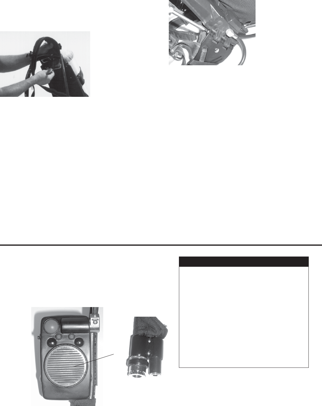
# Description
1 PASS Panic button
2 Shift key: select voice level activation
3 Function key: select On/Off for VAS
4 Right LED: green = console power on
red = low battery indicator
5 Left LED: green = PASS on
flashing red = PASS pre or full
alarm
6 PTT - push to talk button for radio com
7 Center speaker for VAS and radio com
8 PASS reset buttons power on/off buttons
9 Radio interface connection
10 Facemask interface power cable
11 Pressure transducer connection
Chart for Control Console Keys and Description
.1 CONTROL CONSOLE KEYS & FUNCTIONS
.1.1 The control console is mounted on the upper left
shoulder strap. As with the HUD, the console turns
on automatically when the cylinder valve is opened.
The control console has several function buttons.
Please review the following diagram for locations
and the chart for function. All locations are from
the user's perspective.
9.0 VIKING Z SEVEN OPTIONS
Note: At 3.8V, low battery indicators will display
<120 psi = HUD will not display any lights
Auto off delay - after cylinder is closed, console
will turn off automatically after 2 minutes on non-
pass units.
7
23
564
8
111
8
(not pictured)
9
10

COPYRIGHT 2007 AVON - ISI 19
Level HUD LED Pattern
1 Flashing Red
2 Red, Flashing Yellow
3 Red, Yellow, Flashing Green
4 Red, Yellow, Green, Flashing Green
5 Red, Yellow, Green, Green
6 Flashing Red, Low bat
7 Red, Flashing Yellow, Low Bat
8 Red, Yellow, Flashing Green, Low Bat
9 Red, Yellow, Green, Flashing Green, Low Bat
10 Red, Yellow, Green, Green, Low Bat
1 2 3 4 5 6 7 8 9 10
9.1.2.3 RADIO INTERFACE
When the Z SEVEN is equipped with radio interface,
it has the ability to significantly decrease the back-
ground noise of outgoing transmissions. This is due
to the placement of the sealed microphone inside
the nosecup, which is well insulated from ambient
noise. Incoming transmissions are broadcast from
the console speaker. On units designed for use by
law enforcement, incoming transmissions are re-
cieved through an optional ear speaker.
A separate radio lead is required to integrate the
console to the radio. The radio connects to the inter-
face cable on the lower control console.
There are two ways to key the radio and transmit: in
the manual mode, press and hold the Push-To-Talk
button (PTT) on the side of the console. As an indi-
cation that the PTT button has been pressed, the
right LED indicator light turns green on in the con-
sole display and a solid green light on the HUD. If
VAS is installed with Radio Interface, the VAS is dis-
abled whenever the radio is keyed.
To activate the hands free VOX mode, press and re-
lease the PTT button twice within one second (dou-
ble click). A flashing red light will illuminate on the
control console display. In this mode, the radio is
keyed automatically whenever the SCBA senses
user speech. The HUD will illuminate only the top
green (full) light whenever user speech has keyed
the radio. When speech has ended, the unit auto-
matically turns off the amplifier to conserve the bat-
tery and the HUD again monitors cylinder pressure.
To end the hands free mode, double click the PTT
button again.
.1.2 COMMUNICATIONS
The Viking Z SEVEN is available with several communication
ptions. The microphone is a standard feature and is mount-
d inside the facemask on the nosecup. It offers excellent
peech clarity. All communications have a noise suppressor
o reduce exhaled breathing air noise.
Note: The Viking Z SEVEN electronics and pneumatics
turn on automatically when the cylinder valve is
opened. The SCBA electronics can be turned on
manually by depressing the lower two ON/OFF but-
tons on the console.
.1.2.1 VOICE AMPLIFICATION SYSTEM (VAS)
The VAS uses a sealed, in-mask microphone to cap-
ture the user's voice, amplifies it, and then broad-
casts it from the speaker on the console. This is par-
ticularly useful in communicating with other people
nearby when the SCBA is in the positive pressure
mode. VAS is preset to be voice activated. You must
speak slightly louder than normal to activate VAS.
The VAS is on standby mode whenever the SCBA
cylinder is opened. When speech is sensed, it turns
on the amplifier and sends it to the console. Shortly
after speech ends, the amplifier goes back into
standby mode.
VAS can be turned off if the user desires. To turn off
the VAS, the cylinder valve must be opened and
power activated to the control console. To disable
the VAS, push inward on the Function key and push
the PTT button. An audible chirp should be heard.
VAS is now in the off setting. To turn VAS back on,
repeat the above function. When the Viking SCBA is
powered down, the system will defaut to VAS "on"
when the electronics are activiated.
9.1.2.2 VOICE ACTIVATION LEVELS
The microphone activation level is adjustable for in-
dividual preference. Push the Shift button on the
front of the console inward and hold. The HUD face-
mask display will flash the preset point of the voice
activation level. To change the settings, while hold-
ing the Shift key, push the PTT button once. This will
raise the activation point. Continue to push the PTT
to your personal preference. Release the Shift key to
set activation level. To go from Level 4 to Level 1,
hold the Shift key inward and push the PTT button
again.
There are four set points for the voice activation lev-
el. Level 1 is the most sensitive activation point up to
a Level 4 being the least sensitive activation point.
Each level will be displayed a specific number of
HUD light(s) that activate. With each increased level,
less inhalation breathing noise is heard, but voice
must be raised higher to begin amplification in order
for the microphone to detect speach. The settings
are a follows:
Amount breathing noise
amplified
COPYRIGHT 2007 AVON - ISI
20
9.1.3 VIKING Z SEVEN PASS
The PASS on the Viking Z Seven is an NFPA 1982
compliant Personal Alert Safety System (PASS) that
is integrated with the SCBA and with the other elec-
tronic systems. It requires no adjustments.
The PASS is automatically activated when the
cylinder is opened or may be manually turned on by
pushing both "ON/OFF" side buttons on the console
simultaneously. Once turned on, it normally operates
in the “sensing” mode where it looks for motion at the
console.
9.1.3.1 PASS Operating Instructions
WARNING
ALWAYS TEST THE PASS PRIOR TO ENTRY INTO
A HAZARDOUS ATMOSPHERE. IF THE LOW BAT-
TERY WARNING SIGNAL ACTIVATES, INSTALL
NEW BATTERIES AFTER USE OR PRIOR TO USING
THE VIKING Z SEVEN. THE CONTROL CONSOLE
WITH PASS SHOULD BE POSITIONED FLAT
AGAINST THE SHOULDER STRAP.
When the PASS is turned on, a chirp will be heard on
the control console speaker, followed by a chirp from the
PASS alarm on the backpack. Additionally, the left LED users
prospective on the console display will slowly flash green
when PASS is on. When there is a lack of motion sensed at
the control console or PASS device in backframe for over 25
seconds, the PASS will go into pre-alarm and sound an audi-
ble warning that will progressively get louder until the PASS
goes into full alarm. While in pre-alarm, the red (¼ full) and
top green (full) lights on the HUD will flash and the PASS LED
light on the console will change to rapidly flashing red. In pre-
alarm, motion to the control console or pushing the side but-
tons on the console will return the PASS to the sensing mode.
If no motion is sensed for a full 35 seconds (including the pre-
alarm warning), the PASS will go into full alarm and can only
be reset by pushing in on the two side ON/OFF buttons on the
console.
9.1.3.2 PASS Safety Certification and Approval
• The Viking Z SEVEN with PASS is Certified Intrinsi-
cally Safe for use in Class 1, Division 1, Group A, B, C
and D Hazardous Locations.
• NFPA Specification: Meets the current NFPA 1981,
2007 edition specifications and NPFA 1982, 2007
edition.
• NIOSH Specification: Meets the standards of 42CFR,
Part 84
9.1.3.3 PASS Specifications
Alarm level: greater than 95 dbA @ 3 m (approximately
10 ft)
Visual / Audio Indicators:
Turn ON Chirp from Console speaker, then chirp from
PASS alarm, and flashing green PASS light.
Turn OFF Low beep from console speaker
Pre-alarm (No motion sensed for 25 seconds):
PASS light turns from green to red and flash
rate increases
End lights on mask display flash alternately
Pre-alarm warning with increasing sound
level
Alarm (No motion sensed for 35 seconds):
PASS alarm sounds
PASS LED light on console flashes red
Mask display shows cylinder pressure
Maintenance After each use, clean the control console with a
damp cloth and warm water. Do not use cleaning
solvents. Inspect each unit for signs of physical
damage.
Life Depending on the frequency of use, the PASS
may have to be retired from service if severely
damaged.
9.1.3.4 PASS Limitations
The VIKING Z SEVEN is designed to meet the de-
sign and performance requirements for Personal
Alert Safety Systems (PASS) to be used by firefight-
ers engaged in rescue, fire fighting, and other haz-
ardous duties defined in the NFPA 1982 Standard
on PASS, 2007 edition. Failure to ensure that the Vi-
king Z SEVEN PASS is fully operational prior to use
may expose the user to serious injury or death. Al-
though the Viking Z SEVEN PASS meets the current
standards, there is no guarantee against PASS fail-
ure. Most performance properties of the PASS can-
not be tested by users in the field.
9.1.3.5 PASS Warranty
AVON-ISI warrants the Viking Z SEVEN PASS to be
free from defects in workmanship and materials for a
period of one year from date of purchase. AVON-ISI
will not repair or replace any merchandise that has
been damaged from accident, misuse, or abuse
while in the possession of the end-user. AVON-ISI
shall not be liable for any direct, incidental or other
consequential loss or damage arising out of the fail-
ure of the device to operate. PASS issues may be
reported to AVON-ISI Customer Service at (888)
474-7233. After working with the manufacturer to re-
solve any issues, they may be reported to SEI at
(703) 525-2354.
9.2 VIKING STEALTH MODE
The Viking Z-ST model designed for law enforcement has the
capability of turning off the control console. The Stealth Mode
is a standard feature of the Viking Z-ST.
On units with the stealth mode option, depress the funtion
key and the PPT button on the control console for one sec-
ond to turn off VAS. The HUD will still display cylinder pres-
sure and acknowledge radio transmissions. All communica-
tions will be received through the optional ear piece interface
cable. To reset to normal mode, depress the function key and
PTT button on the control console for one second.
COPYRIGHT 2007 AVON - ISI 21
Viking SCBA.
9.3.2.1 The EAS tether is designed so you do not have to
unplug the regulator hose from the facemask in an
IDLH atmosphere. The EAS tether includes two feet
of retractable hose stored within the backframe. The
end of the hose includes two couplings, one male
and one female, and a combination handle/dust cap.
When stored, the EAS handle is located on the lower
right side of the backframe (from the user’s perspec-
tive). In an emergency, the EAS tether is pulled out
of the backframe and connected to another EAS teth-
er forming a four foot long combined tether hose.
9.3.2.2 If the EAS is used, egress immediately to a safe, re-
spirable atmosphere. The rescuer must monitor their
cylinder air closely due to increased air consumption.
9.3.2.3 Although the EAS is a NIOSH accepted SCBA ac-
cessory, NIOSH does not approve the use of EAS
devices. Use of the EAS voids NIOSH approvals
while in use.
9.3.2.4 REMOVE THE EAS TETHER: Using your right
hand, reach back above the cylinder valve knob and
locate the buddy breather handle. Pull down on the
handle and completely pull out the hose. The tether
is approximately two feet long.
9.3.2.5 CONNECT TO ANOTHER EAS TETHER: Each
EAS tether includes both male and female quick
connect couplings. Connect one coupling, either
male or female, to the opposite coupling on the other
EAS tether. Air will start to flow immediately.
9.3.2.6 Egress to a safe, respirable atmosphere and then
disconnect EAS tethers.
9.3.2.7 To store EAS tether, while the SCBA pneumatics are
pressurized, push the hose length back into the
backframe. Snap the handle into the backframe and
replace dust caps.
IMPORTANT
9.3 ADDITIONAL OPTIONS
9.3.1 AIRLINE DESCRIPTION, LIMITATIONS &
OPERATION
Note: Airline options are available on all models of the Vi-
king SCBA.
9.3.1.1 The Airline Attachment is located on the left waist-
belt strap. It is approved with Hansen HK. Hansen
HK couplings include locking devices.
IMPORTANT
Only Hansen HK airline fittings are offered on CBRN certified
units.
The use of airline attachments on CBRN approved units are
not NIOSH CBRN approved for use in confirmed or potential
CBRN environments.
9.3.1.2 When using supplied air, the user must ensure that
the cylinder valve is closed. Failure to do so may re-
sult in reduced cylinder duration.
9.3.1.3 Airline respirators can be used only when the respi-
rators are supplied with respirable air meeting the re-
quirements of CGA G-7.1 Grade D or higher quality.
9.3.1.4 When used as a combination apparatus, only 20% of
the service pressure may be used on entry.
9.3.1.5 This approval applies only when the device is sup-
plied with respirable breathing air through 6 to 300
feet of hose at air pressures between 80 to 120
pounds per square inch gauge or from self contained
air supply.
9.3.1.6 Follow Donning Procedures located in Section 3.0
and Safety Checks in Section 3.2.
9.3.1.7 Plug airline hose from Viking into supplied airline
hose. Supplied air pressure shall be between 80 to
120 psi. Close cylinder valve and continue to
breathe normally. If supplied air is interrupted, open
cylinder valve fully, unplug airline hose and then
egress to a safe area.
9.3.1.8 Take necessary actions to monitor the supplied air
source pressure while operating with supplied air.
9.3.1.9 To transfer from supplied air to cylinder air, open
cylinder valve first. Disconnect supplied air hose by
retracting coupling sleeve.
9.3.2 ESCAPES AIR SYSTEM (EAS) DESCRIPTION,
LIMITATIONS & OPERATION
Note: The EAS option is available on all models of the
Pull Down

COPYRIGHT 2007 AVON - ISI
22
International Safety Instruments, Inc. (AVON-ISI) warrants
the VIKING SCBA to the original owner to be free from de-
fects in materials and workmanship from the date of shipment
from AVON-ISI’s factory for 15 years of this product. To main-
tain this warranty, the purchaser must perform maintenance
and inspections as prescribed in the owner’s instruction man-
ual, which shall include prompt replacement or repair of de-
fective parts, and replacement of parts per the maintenance
schedule as prescribed in the owner’s instruction manual.
This warranty does not apply to expendable or consumable
parts whose normal life expectancy is less than one (1) year.
AVON-ISI’s obligation under this warranty is limited to replac-
ing or repairing, at AVON-ISI’s option, any defective part if re-
turned to AVON-ISI in Lawrenceville, GA, or an AVON-ISI au-
thorized service center. Shipping charges are to be prepaid
by the buyer. Upon inspection, AVON-ISI will repair all prod-
ucts that prove to have been defective due to defects in ma-
terials and/or workmanship. AVON-ISI shall be released from
all obligations under this warranty in the event repairs or
modifications are made by persons other than its own or au-
thorized service personnel, or if the warranty claim results
from misuse of the product.
AVON-ISI warrants the Viking Digital’s solid- state compo-
nents to be free from defects in workmanship and materials
for a period of one (1) year from the date of purchase.
In addition, this warranty does not apply to elastomer or rub-
ber components since they can be adversely affected by un-
due exposure to heat, sun, water, chemicals, ozone, or other
deteriorating elements. Also excluded from this warranty are
facemask lenses, compressed-air cylinders and parts that be-
come defective through normal use. The decision as to what
constitutes normal use shall be made solely by AVON-ISI.
AVON-ISI will not repair or replace under warranty any mer-
chandise that has been damaged from accident, alteration,
misuse, or abuse while in the possession of the end-user.
AVON-ISI shall not be liable for any direct, incidental or other
consequential loss or damage arising out of the failure of the
device to operate.
THIS WARRANTY IS EXPRESSLY IN LIEU OF ALL OTHER
WARRANTIES, EXPRESSED, IMPLIED, OR STATUTORY,
AND IS STRICTLY LIMITED TO THE TERMS HEREOF.
AVON-ISI SPECIFICALLY DISCLAIMS ANY WARRANTY OF
MERCHANTABILITY OR OF FITNESS FOR A PARTICULAR
PURPOSE. AVON-ISI neither assumes nor authorizes any
other person or firm to assume on AVON-ISI’s behalf any lia-
bility in any way connected with the sale of AVON-ISI prod-
ucts.
To validate this warranty, the Warranty & Registration Card
supplied with the apparatus MUST be detached, completed,
and returned to AVON-ISI WITHIN 30 DAYS of purchase.
10.0 VIKING SCBA WARRANTY

COPYRIGHT 2007 AVON - ISI 23
If corrections by a Certified AVON-ISI Service Technician DO NOT resolve the
problem, tag the unit "Out of Service" and have the SCBA serviced by an
AVON-ISI Certified Service Center.
Pressure Display on wrong setting.
May be on 2216 (low pressure) when
4500 (high pressure) unit.
Lights in the facemask turn on
slowly as cylinder is opened. Bad
transducer
1. Radio
2. Interface lead
1. Facemask board
2. Bad speaker or speaker wire
3. Control Console
4. Turn VAS "on"
Poor facemask electronics contact
Two lights "on" with full cylinder
Cylinder pressure, slow reacting
Radio interface interference
VAS not working
VAS with static noise
Turn on Control Console and check
pressure: should read "22" for low
pressure and "45" for high pressure. If
on wrong setting, remove battery pack,
push and hold in PTT button and
install battery pack. Cycle back and
forth using PTT button
Tag for repair
1. Check radio on another Viking
2. Check interface lead on another
Viking. If background noise, touch
lead at Viking connection to ground
connection. If noise stops, need new
interface lead.
1. Tag for repair
2. Tag for repair
3. Tag for repair
4. Tag for repair
Lubricate facemask electronics plug
with diolectric grease.
PROBLEM POSSIBLE CAUSE CORRECTION
11.0 TROUBLESHOOTING GUIDE
Note: Only AVON-ISI trained technicians are qualified to perform repairs that require any adjustments or replacement of parts. This
troubleshooting guide is to help aid the user in determining the cause of the problem and not meant to be a quick guide in doing re
pairs.

COPYRIGHT 2007 AVON - ISI
TABLE OF CONTENTS
PREFACE-IMPORTANT POINTS 1
Intent 1
Training 1
Approvals 1
NIOSH warnings 1
Cautions and Limitations 2
Special or Critical User Instructions 2
1.0 DESCRIPTION OF VIKING SCBA 3
1.1 Facemask 3
1.2 AirSwitch Regulator 3
1.3 RDV Regulator 3
1.4 First Stage Pressure Reducer 3
1.5 End-of-Service Alarms 4
1.6 Backframe and Harness 4
1.7 Control Console 4
1.8 Cylinder and Valve Assembly 4
1.9 Rapid Intervention Crew Fitting 5
1.10 Viking Cylinder Table 5
2.0 ROUTINE CHECKS 6
2.1 Unpacking 6
2.2 Inventory and Examination 6
2.3 Routine Checks and Inspections 6
2.4 SCBA Retirement 7
3.0 DONNING PROCEDURES AND SAFETY
CHECKS 8
3.1 Donning Procedures 8
3.2 Safety Checks 10
4.0 DURING USE 11
4.1 Reading the Heads-Up Display 11
4.2 Normal Use 12
4.3 CBRN Specific Actions 12
4.4 Instructions for Changing Cylinders 12
4.5 Cylinder Band Adjustment 12
4.6 Emergency Egress Indicators 12
4.7 RIC Fitting Procedures 13
5.0 AFTER USE PROCEDURES 14
5.1 Doffing 14
6.0 AFTER USE CLEANING AND CYLINDER
CHANGING 15
6.1 Clean AirSwitch Regulator/Facemask 15
6.2 Clean RDV Facemask 15
6.3 Cleaning SCBA 15
7.0 SCBA STORAGE 16
7.1 SCBA Storage 16
8.0 USER MAINTENANCE 16
8.1 Maintenance Intervals 16
8.2 Cylinder Filling Procedures 16
8.3 Battery Pack 16
8.4 Facemask Harness Replacement 17
8.5 Backframe Harness Removal 17
9.0 VIKING OPTIONS 18
9.1 Control Console Keys & Functions 18
9.2 Stealth Mode 20
9.3 Additional Options 20
10.0 WARRANTY 22
11.0 TROUBLESHOOTING GUIDE 23

COPYRIGHT 2007 AVON - ISI
Viking Z SEVEN SCBA
User's Manual
AVON- ISI
922 Hurricane Shoals Road
Lawrenceville, GA 30043
Phone: 770-962-2552
Fax: 770-963-2797
www.intsafety.com
Part Number: 084126 Rev. A
Artwork Number: A49257 Rev. A
February 19, 2007
ISO 9001 Certified
WARNING
Disassembly of the components beyond the procedures described herein shall not be
performed. Additional disassembly may cause component damage and shall only be per-
formed by ISI authorized personnel or the factory.
VIKING Z SEVEN CBRN MODELSVIKING Z SEVEN CBRN MODELS
VIKING Z SEVEN CBRN MODELSVIKING Z SEVEN CBRN MODELS
VIKING Z SEVEN CBRN MODELS
VIKING Z SEVEN 2216 PSI, 30 MINUTE
NIOSH APPROVAL TC-13F-XXX
VIKING Z SEVEN 4500 PSI, 30 MINUTE
NIOSH APPROVAL TC-13F-XXX
VIKING Z SEVEN, 4500 PSI, 45 MINUTE
NIOSH APPROVAL TC-13F-XXX
VIKING Z SEVEN, 4500 PSI, 60 MINUTE
NIOSH APPROVAL TC-13F-XXX
AVON - ISI