Safety Technology 34080 Transmitter for use in a wireless alert system User Manual
Safety Technology International, Inc. Transmitter for use in a wireless alert system
Contents
- 1. User Manual
- 2. User Manual Rev
User Manual

Rhein Tech Laboratories, Inc. Client: STI
360 Herndon Parkway Model: STI-34080
Suite 1400 Standards: FCC 15.231/IC RSS-210
Herndon, VA 20170 ID’s: TXL34080/6335A-34080
http://www.rheintech.com Report #: 2013282
26 of 29
Appendix L: Manual
Please refer to the following pages.
STI (Europe) - Unit 49G Pipers Road, Park Farm Ind. Estate, Redditch, Worcs. UK
Tel: +44 (0) 1527 520999 - Fax: +44 (0) 1527 501999
info@sti-europe.com - www.sti-europe.com
STI (Europe) - Spain C/La Union 25, Altea, Alicante, Espana
Telefono/Fax: +34 966 880785 - Movil: +34 664 828977
educardo@sti-europe.com - www.sti-europe.es
STI, Inc. - 2306 Airport Rd., Waterford, Michigan 48237, USA
Tel: 248-673-9898 - Fax: 248-673-1246
info@sti-usa.com - www.sti-usa.com
Euro Stopper® STI-15000 Series
The Euro Stopper is a sleek protective cover that offers protection
against tampering, vandalism and damage from accidental activation.
Specifications
• Input power 3V Lithium CR123A, 12-24 VDC - remote power
• Flammability: UL94 V-2
• Temperature range:
· Polycarbonate Rated: -40° to 121°C (-40° to 250°F)
· Electronics Operating Range: -10° to 49°C (14 to 120° F)
· Note: below -10°C a remote power source is recommended
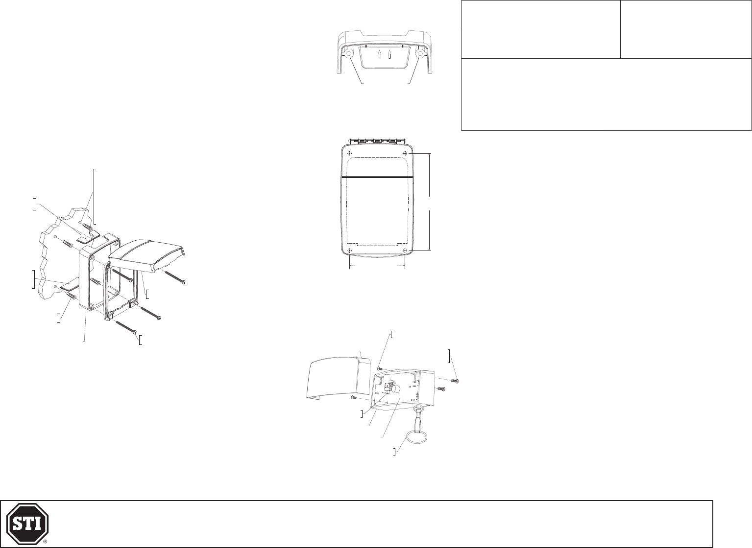
Mounting Instructions
1. Position the Euro Stopper® over the device to be protected, open the front
cover of the Euro Stopper® and mark the position for the four (4) mounting
screws.
2. Drill holes and attach the Euro Stopper® to the wall using the screws provided.
See Fig. 1 for drill sizes.
3. If a surface spacer is included, ensure the isolated (inner) mounting columns
are at the top (Fig. 2).
Note: The spacer is not reversible; arrows are marked upwards on the removable
plastic windows for your convenience (Fig. 2).
WHEN USING ANCHORS,
DRILL 1/4 in. (7mm)
DIA. HOLES 1 1/4 in.
(31.75mm) DEEP
IF USING SCREWS ONLY, DRILL
9/64 in. (3.5mm) DIA. HOLES
1 1/4 in. (31.75mm) DEEP
EURO STOPPER
ASSEMBLY
SCREWS
(4) PROVIDED
32mm SPACER
ANCHORS
(4) PROVIDED
WINDOW
FOR SPACER
(2) PROVIDED
WINDOW
FOR CONDUIT
4. The 32mm (1.25”) and 50mm (2”) surface spacer provides cable entry
facilities for conduit, cable and trunking.
5. For surface installations, use the windows attached to the spacer to ll
in any unused cable/conduit entry points.
MOUNTING COLUMNS
Fig. 1
Fig. 2
86mm (3.4 in.)
TEXT HERE
152mm
(6 in.)
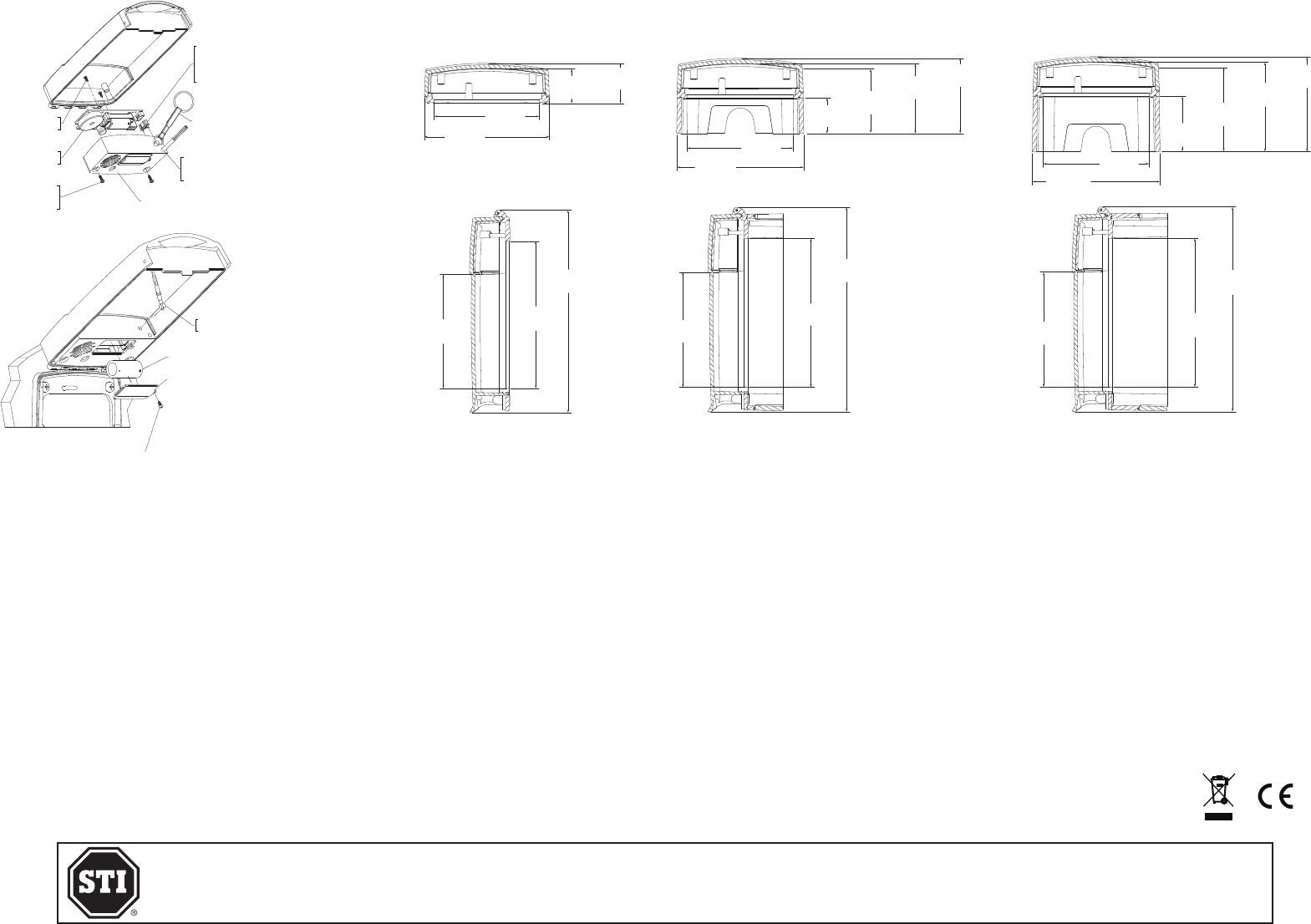
Circuit Board Operations
1. On initial installation, activate the battery by removing the battery
cover using a small Phillips screwdriver. Remove red tape.
2. To adjust the volume using the Hi/OFF/Lo switch, remove horn case
(see Fig. 4 for location).
3. If using 12/24VDC & Relay Cord:
a. Remove horn case or keep off after adjusting volume.
b. Remove PCB by removing the two (2) screws as shown in Fig. 5.
Lift PCB as far as the wires allow.
c. Drill a 5mm hole (3/16”) at the witness point shown on Fig. 5.
d. Then insert the wire harness cord into the socket as shown in Fig. 5.
e. Leaving a small amount of slack, push the harness into the drilled
outlet hole.
f. Secure PCB into place and reattach horn case with two (2) provided
screws.
g. CAUTION: The relay will not operate with the service pin in
place.
Fig. 3
Alarm Current:
3V Battery 12V 24V Volume
- Standby 10µA 500µA 550µA Distance 1M (3 Ft) 3M (10 Ft)
- Low 40mA 38mA 22mA Low 72 dB 64 dB
- High 105mA 125mA 95mA High 96 dB 88 dB
Wire Description
RED + REMOTE INPUT Form “C”
BLACK - POWER 12-24VDC Dry Contact Relay
BLUE COMMON - 30VDC, 1A
GREEN NC: NORMALLY CLOSED - 125VAC, 0.5A
YELLOW NO: NORMALLY OPEN - 60VDC, 0.3A
12/2013
}
}
SERVICE PIN
(1) PROVIDED
M276 HORN CASE
34080 PCB SOUNDER
#4 x .312 in.
HI-LOW SCREW
(2) PROVIDED
#2 x .25 in. SMS
(2) PROVIDED
M272 HORNSHELL
VOLUME SWITCH
HI/OFF/LO
Fig. 4
STI (Europe) - Unit 49G Pipers Road, Park Farm Ind. Estate, Redditch, Worcs. UK
Tel: +44 (0) 1527 520999 - Fax: +44 (0) 1527 501999
info@sti-europe.com - www.sti-europe.com
STI (Europe) - Spain C/La Union 25, Altea, Alicante, Espana
Telefono/Fax: +34 966 880785 - Movil: +34 664 828977
educardo@sti-europe.com - www.sti-europe.es
STI, Inc. - 2306 Airport Rd., Waterford, Michigan 48237, USA
Tel: 248-673-9898 - Fax: 248-673-1246
info@sti-usa.com - www.sti-usa.com
SERVICE PIN
(1) PROVIDED
#2 x .25 in. SMS
M277 BATTERY COVER
CR123A BATTERY
Fig. 6
Optional Wireless Transmitter Version
1. The supervised wireless sounder version is capable of transmitting a 433MHz alert to any
STI Receiver (range up to 500 ft.)
2. When lifting the cover, the wireless Euro Stopper® will send an alert to an STI receiver. For
enrolling this device, refer to STI receiver installation instructions.
3. On closing the cover, the wireless Euro Stopper® will send a restore signal to an STI receiver.
4. CAUTION: This device will transmit an alert even with the service pin in place.
Replacing the Battery
1. The Euro Stopper® sounder will emit an audible beep when the battery becomes low.
2. Lift cover and insert the service pin.
3. Using a small Phillips screwdriver, remove the battery cover.
4. Replace 3V CR123A Lithium battery, taking care to observe the polarity as marked.
5. Reassemble the battery cover and screws, then remove the service pin to arm.
Optional Break Seals
1. There are two (2) locking tabs, one (1) on each side of the frame. Choose which side the
break seal is to be located, close the cover and carefully drill a 3mm (.118”) diameter hole
at the witness point.
2. Once the device is ready to be protected, remove the service pin (if applicable), close the
cover and lock the break seal in place.
A
A
BB 104mm
(4.11 in.)
185mm
(7.30 in.)
135mm
(5.30 in.)
32mm
(1.25 in.)
37mm
(1.45 in.)
94mm
(3.70 in.)
114mm
(4.50 in.)
C
C
DD 104mm
(4.11 in.)
135mm
(5.30 in.)
185mm
(7.30 in.)
32mm
(1.26 in.)
58mm
(2.30 in.)
63mm
(2.48 in.)
68mm
(2.68 in.)
94mm
(3.70 in.)
115mm
(4.53 in.)
C
C
DD 135mm
(5.30 in.)
185mm
(7.30 in.)
1.4mm
(4.11 in.)
50mm
(1.97 in.)
76mm
(3 in.)
81mm
(3.2 in.)
86mm
(3.39 in.)
94mm
(3.70 in.)
116mm
(14.56 in.)
A
A
BB
104mm
(4.11 in.)
185mm
(7.30 in.)
135mm
(5.30 in.)
32mm
(1.25 in.)
37mm
(1.45 in.)
94mm
(3.70 in.)
114mm
(4.50 in.)
C
C
DD 104mm
(4.11 in.)
135mm
(5.30 in.)
185mm
(7.30 in.)
32mm
(1.26 in.)
58mm
(2.30 in.)
63mm
(2.48 in.)
68mm
(2.68 in.)
94mm
(3.70 in.)
115mm
(4.53 in.)
C
C
DD 135mm
(5.30 in.)
185mm
(7.30 in.)
1.4mm
(4.11 in.)
50mm
(1.97 in.)
76mm
(3 in.)
81mm
(3.2 in.)
86mm
(3.39 in.)
94mm
(3.70 in.)
116mm
(14.56 in.)
A
A
BB 104mm
(4.11 in.)
185mm
(7.30 in.)
135mm
(5.30 in.)
32mm
(1.25 in.)
37mm
(1.45 in.)
94mm
(3.70 in.)
114mm
(4.50 in.)
C
C
DD 104mm
(4.11 in.)
135mm
(5.30 in.)
185mm
(7.30 in.)
32mm
(1.26 in.)
58mm
(2.30 in.)
63mm
(2.48 in.)
68mm
(2.68 in.)
94mm
(3.70 in.)
115mm
(4.53 in.)
C
C
DD 135mm
(5.30 in.)
185mm
(7.30 in.)
1.4mm
(4.11 in.)
50mm
(1.97 in.)
76mm
(3 in.)
81mm
(3.2 in.)
86mm
(3.39 in.)
94mm
(3.70 in.)
116mm
(14.56 in.)
A
A
BB 104mm
(4.11 in.)
185mm
(7.30 in.)
135mm
(5.30 in.)
32mm
(1.25 in.)
37mm
(1.45 in.)
94mm
(3.70 in.)
114mm
(4.50 in.)
C
C
DD
104mm
(4.11 in.)
135mm
(5.30 in.)
185mm
(7.30 in.)
32mm
(1.26 in.)
58mm
(2.30 in.)
63mm
(2.48 in.)
68mm
(2.68 in.)
94mm
(3.70 in.)
115mm
(4.53 in.)
C
C
DD 135mm
(5.30 in.)
185mm
(7.30 in.)
1.4mm
(4.11 in.)
50mm
(1.97 in.)
76mm
(3 in.)
81mm
(3.2 in.)
86mm
(3.39 in.)
94mm
(3.70 in.)
116mm
(14.56 in.)
A
A
BB 104mm
(4.11 in.)
185mm
(7.30 in.)
135mm
(5.30 in.)
32mm
(1.25 in.)
37mm
(1.45 in.)
94mm
(3.70 in.)
114mm
(4.50 in.)
C
C
DD 104mm
(4.11 in.)
135mm
(5.30 in.)
185mm
(7.30 in.)
32mm
(1.26 in.)
58mm
(2.30 in.)
63mm
(2.48 in.)
68mm
(2.68 in.)
94mm
(3.70 in.)
115mm
(4.53 in.)
C
C
DD 135mm
(5.30 in.)
185mm
(7.30 in.)
1.4mm
(4.11 in.)
50mm
(1.97 in.)
76mm
(3 in.)
81mm
(3.2 in.)
86mm
(3.39 in.)
94mm
(3.70 in.)
116mm
(14.56 in.)
A
A
BB 104mm
(4.11 in.)
185mm
(7.30 in.)
135mm
(5.30 in.)
32mm
(1.25 in.)
37mm
(1.45 in.)
94mm
(3.70 in.)
114mm
(4.50 in.)
C
C
DD 104mm
(4.11 in.)
135mm
(5.30 in.)
185mm
(7.30 in.)
32mm
(1.26 in.)
58mm
(2.30 in.)
63mm
(2.48 in.)
68mm
(2.68 in.)
94mm
(3.70 in.)
115mm
(4.53 in.)
C
C
DD
135mm
(5.30 in.)
185mm
(7.30 in.)
1.4mm
(4.11 in.)
50mm
(1.97 in.)
76mm
(3 in.)
81mm
(3.2 in.)
86mm
(3.39 in.)
94mm
(3.70 in.)
116mm
(14.56 in.)
Caring for Polycarbonate
Rinse with warm water to remove dust and dirt. Wash with soap or mild detergent. Concentrated solutions and those including
(but not limited to) alkalis, strong acids, ethers, amines, aromatic hydrocarbons and alcohols can cause considerable harm to
this product. Rinse once more then dry with a soft cloth or chamois. DO NOT use sharp objects that may scratch the surface.
Exercise caution when using water inside the enclosure and ensure the unit is completely dry inside before reassembling.
Warranty
Three (3) year guarantee against breakage of polycarbonate in normal use (one (1) year on electronic components).
Warranty form at www.sti-usa.com/wc14
IMPORTANT NOTICE
This device complies with Industry Canada license-exempt RSS standard(s). Operation is subject to the following two
conditions: (1) this device may not cause interference, and (2) this device must accept any interference, including interference
that may cause undesired operation of the device.
Le présent appareil est conforme aux CNR d’Industrie Canada applicables aux appareils radio exempts de licence. L’exploitation
est autorisée aux deux conditions suivantes : (1) l’appareil ne doit pas produire de brouillage, et (2) l’utilisateur de l’appareil
doit accepter tout brouillage radioélectrique subi, même si le brouillage est susceptible d’en compromettre le fonctionnement.
Contains FCC ID: TXL34080 Model: STI-34080
Fig. 7
DIMENSIONAL DRAWINGS
Surface Mount 32mmFlush Mount Surface Mount 50mm
12/2013
OPTIONAL 5 PIN
CONNECTOR
WIRE HARNESS
12/24 VDC
SERVICE PIN
#2 x .25 SMS
(2) PROVIDED
34080
PCB SOUNDER
#4 x .312
HI-LOW SCREW
(2) PROVIDED M276 HORN CASE
DRILL
3/16 in. (5mm)
HOLE THRU
Fig. 5
END
VIEW
SIDE
VIEW
IC: 6335A-34080