Sagem Wireless 95310001 Wireless Local Loop Terminal User Manual H S EN COURS TRA TRA 2
Sagem Wireless Wireless Local Loop Terminal H S EN COURS TRA TRA 2
Users Manual
S
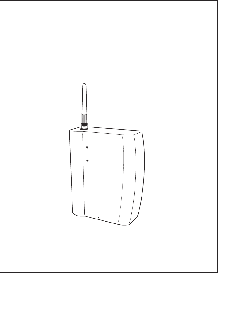
BASIC GUIDE to the Digital Terminal
MODEL RT30F - PCS

1
Welcome to the world of the SAGEM SA local radio loop. We congratulate you on your
purchase of a GSM digital terminal SAGEM RT-30.
We would like to draw your attention to the fact that this GSM terminal has been approved
in accordance with the relevant European Standard. To get the most out of your digital
terminal and the services associated with it, we recommend that you carefully read through
this Basic Guide and keep it near your digital terminal.
PLEASE NOTE
Depending on the configuration of the networks and the associated conditions of
subscription, some functions may not be available (these are indicated by an
asterisk *).
The SAGEM logo and trademark are the property of SAGEM SA.
AT is a registered trade mark of Hayes Microcomputer Products, Inc.
Hayes is a registered trade mark of Hayes Microcomputer Products, Inc.
Windows is a registered trade mark of Microsoft Corporation.
All other trade marks or product names are trade marks or product names of the respective title holders.
ZAMBUUUJO.p65 10/04/02, 18:431

2
GENERAL RECOMMENDATIONS .................................................................. 3
Safety instructions ........................................................................................ 3
Electrical safety ............................................................................................ 4
FCC Recommandations Safety information for Wireless local loop
Terminal ........................................................................................................ 5
YOUR TERMINAL ............................................................................................. 9
Your box contains ......................................................................................... 9
Description of your terminal ......................................................................... 9
Connectors ................................................................................................. 10
Lamps ......................................................................................................... 11
Battery .......................................................................................................... 11
INSTALLING AND USING THE TERMINAL FOR THE FIRST TIME ............... 12
Installing your terminal ............................................................................... 13
Connecting line / battery / power supply .................................................... 15
Before connecting, real carefully safety instructions p3 ............................ 16
Commissioning ......................................................................................... 16
Check the field strength ............................................................................. 17
Your first call ............................................................................................... 17
SERVICES AVAILABLE ON THE TERMINAL ................................................. 18
Conference calls * ...................................................................................... 18
Double call (Call hold / Call wait) * ............................................................ 19
Answering device * ..................................................................................... 19
Call forwarding * ......................................................................................... 20
Fax application * ......................................................................................... 20
Data application * ....................................................................................... 21
ADVICE IN THE EVENT OF A PROBLEM ...................................................... 31
Total lack of response from the terminal ................................................... 31
Interruptions during a call .......................................................................... 31
Tone errors ................................................................................................. 31
Generated tones ........................................................................................ 32
Contents
CONTENTS
To make this manual easier to read, carefully study the topics covered and note their
location in the guide:
ZAMBUUUJO.p65 10/04/02, 19:062
3
GENERAL RECOMMENDATIONS
This equipment has to be imperatively installed, tested and serviced by
qualified personnel. Before opening the equipment, always unplug all connectors and
read carefully all safety instructions. After installation or service, the cover must imperatively
be closed and fastened to base with the tie or the screw provided by the manufacturer,
in order to ensure end user safety against electric shocks.
No operator serviceable parts. Refer servicing to qualified personnel. To prevent electric
shocks, do not remove cover.
Safety instructions
Do not allow a child to play with your terminal. He could be injured if he tries to take it
apart (aerial, etc.).
Electronic medical equipment
As with any device which uses radio frequencies, a cellular terminal may adversely affect
the operation of some types of electronic medical equipment if they are not adequately
shielded against interference. This may also apply to medical devices which are carried
in or on the human body (including some types of cardiac stimulator and hearing aids)
and appliances used in the home (dialysis machines in particular).
Contact your doctor or the manufacturer of the device in order to find out whether any
special precautions should be taken.
Potentially explosive areas
Although it can only happen under exceptional circumstances, your terminal or its
accessories are capable of generating sparks which could, in turn, cause an explosion or
start a fire in some potentially hazardous locations (filling stations, etc.). It may also interfere
with remotely-controlled explosive triggering devices, in quarries for example. We therefore
strongly recommend that you do not install your terminal in any of these locations.
The use of your equipment is subject to safety regulations, which are designed to protect
the user and his environment.
Safety instructions
!
ZAMBUUUJO.p65 10/04/02, 18:433
4
GENERAL RECOMMENDATIONS
Electrical safety
Do not install the terminal in a damp room, bathroom, laundry room or in a kitchen
within 1.5 metres of the sink.
This terminal should be used at temperatures between 5°C and 40°C.
In districts which are subject to frequent storms, use a suitable surge arrester to protect
the terminal against electrical overloads.
Electrical connection: 230 V mains power supply, single-phase alternating current, with
the exception of IT installations as defined in Standard EN 60-950.
Note: As an option, you may have a 110V power supply instead of 230V version.
Before powering on your unit, make sure the mains outlet it is connected to, meets the
requirement printed on the warning label on the separate power supply (voltage, current,
frequency of power network).
Note: the mains power supply voltage is classified as excessive according to the criteria
of Standard EN 41-003. As a precaution, in the event of danger, mains adapters should
act as circuit breakers to isolate the 230 V or 110 V or power supply. They must be
located near the terminal and must be easily accessible.
The equipment must only be used with the mains adapter supplied.
In Europe, this unit includes the stamp, following the 73/23/EEC, 89/336/EEC and
93/68/EEC directives.
Telephone line connection:The telephone line is classified as TNV-2 according to EN
60950. Therefore, the line must not be installed outside the building.
Compatibility with your phone
Before connecting your phone to your digital terminal, check the documentation
supplied with the terminal for any information relating to safety.
Make sure that you only connect the terminal to approved phones and in accordance
with current regulations.
Problems with interference
The terminal is a transmitter which uses radio frequencies. For this reason it may
sometimes receive and generate interference which may adversely affect its own
performance as well as the performance of other electrical equipment in the immediate
vicinity (terminals, television sets, microcomputers, etc.).
Make sure that you carefully follow the instructions for connecting your terminal to the
mains power supply.
Recommendations for emergency numbers
The terminal operates with the aid of radio signals on cellular and terrestrial networks.
For this reason, it is not possible to guarantee that every call will be put through. In
addition, you cannot rely solely on a wireless device for urgent communications
(medical emergencies for example).
Electrical safety
ZAMBUUUJO.p65 10/04/02, 18:434

5
FCC Recommandations Safety information for
Wireless local loop Terminal
Use of your Terminal is subject to safety rules designed to protect the user and his or
her environment.
Exposure to Radio Frequency Signals
Your Wireless local loop Terminal is a low power radio transmitter and receiver. When
it is ON, it receives and also sends out radio frequency (RF) signals.
In August, 1996, the Federal Communications Commissions (FCC) adopted RF
exposure guidelines with safety levels for Wireless Terminal. Those guidelines are
consistent with the safety standards previously set by both U.S. and international
standards bodies:
ANSI C95.1 (1992)*
NCPR Report 86 (1986)*
ICNIRP (1996)*
(*) American National Standards Institute; National Council on Radiation Protection and
Measurements; International Commission on Non-Ionizing Radiation Protection.
Those standards were based on comprehensive and periodic evaluations of the relevant
scientific literature. For example, over 120 scientists, engineers, and physicians from
universities, government health agencies, and industry reviewed the available body of
research to develop the ANSI Standard (C95.1).
The design of your phone complies with the FCC guidelines (and those standards).
Safety Operation Requirement
Do not operate your Phonecell when any person is within 20 cm of the antenna.
Antenna Care
Use only the supplied or an approved replacement antenna. Unauthorized antennas,
modifications, or attachments could damage the Terminal and may violate FCC
regulations.
Phone Operation
Tips on efficient operation: for your Terminalto operate most efficiently: do not touch the
antenna unnecessarily when the Terminal is in use. Contact with the antenna affects
call quality and may cause the Terminal to operate at a higher power level than otherwise
needed.
Electronic Devices
Most modern electronic equipment is shielded from RF signals. However, certain
electronic equipment may not be shielded against the RF signals from your Wireless
Terminal
Pacemakers
The Health Industry Manufacturers Association recommends that a minimum
separation of six (6) inches be maintained between a Wireless Terminal and a
pacemaker to avoid potential interference with the pacemaker. These recommendations
are consistent with the independent research by and recommendations of Wireless
Technology Research.
ZAMBUUUJO.p65 18/04/02, 16:175

6
Persons with pacemakers:
•Should ALWAYS keep the phone more than six inches from their pacemaker when the
phone is turned ON;
•If you have any reason to suspect that interference is taking place, turn your Terminal
OFF immediately.
Hearing Aids
Some digital Wireless Terminal may interfere with some hearing aids. In the event of
such interference, you may want to consult your service provider.
Other Medical Devices
If you use any other personal medical device, consult the manufacturer of your device to
determine if they are adequately shielded from external RF energy. Your physician may
be able to assist you in obtaining this information.
Turn your Terminal OFF in health care facilities when any regulations posted in these
areas instruct you to do so. Hospitals or health care facilities may be using equipment
that could be sensitive to external RF energy.
Posted Facilities
Don’t install your Wireless Terminal in any facility where posted notices so require.
Blasting Areas
To avoid interfering with blasting operations, Don’t install your Wireless Terminal when
in a ”blasting area” or in areas posted: ”Turn off two-way radio”. Obey all signs and
instructions.
Potentially Explosive Atmospheres
Don’t install your Wireless Terminal when in any area with a potentially explosive
atmosphere and obey all signs ans instructions. Sparks in such areas could cause an
explosion or fire resulting in bodily injury or even death.
Areas with a potentially explosive atmosphere are often but not always clearly marked.
They include fueling areas such as gasoline stations; below deck on boats; fuel or
chemincal transfer or storage facilities; vehicles using liquefied petroleum gas (such
as propane or butane); areas where the air contains chemicals or particles, such as
grain, dust, or metal powders; and any other area where you would normally be advised
to turn off your vehicle engine.
Electrical Safety
Only use the appropriate chargers recommended in the manufacturer’s catalog. Using
another charger may prove dangerous and could invalidate the warranty of your Wireless
Terminal.
The main power socket should be easily accessible.
Make sure that the main voltage corresponds to the level marked on the charger
identification plate.
General Precautions
Do not try to open your Wireless Termianl and repair it yourself. The manufacturer
cannot be held liable for any resulting damage.
Any work done by an unqualified and unauthorized person will invalidate your warranty.
Do not install your Wireless Terminal in humid places (bathroom, swimming pool, etc.).
Protect it from splashing water and other liquids.
ZAMBUUUJO.p65 10/04/02, 18:516

7
Do not expose your Wireless Terminal to extreme temperatures.
Keep your Wireless Terminal out of reach of small children. Do not allow them to play
with it, it is not a toy. Only use your Wireless Terminal with original accessories. Failure
to comply with these rules will invalidate your warranty.
Remember to dicsconnect the charger before removing the battery.
The physical and chemical processes used in rechargeable batteries mean that
temperature limits must be followed during rapid charging. Your Terminal automatically
protects the batteries from extreme temperatures.
If the Wireless Terminal is disconnected from the battery for an extended period of time,
it will lose the time and the recorded messages.
WARNING
The manufacturer cannot be held liable for any failure to comply with the above
recommendations or for any misuse.
Emergency Calls
IMPORTANT
This Wireless Terminal, like any PCS phone, operates using radio signals, PCS and
landline networks, and user-programmed functions. As a consequence a connection in
all conditions cannot be guaranted.Therefore you should never rely solely upon any
PCS phone for essential communications (e.g. medical emergencies).
To make or receive any calls, this phone must be switched on and in service area with
adequate PCS signal strength. Emergency calls may not be possible on all PCS
networks or when certain network services and/or phone features are in use. Check
with local Service Providers.
When making an emergency call, remember to give all the necessary information as
accurately as possible. Remember that your PCS Wireless Terminal may be the only
means of communication at the scene of an accident - do not terminate the call until
given permission to do so.
If certain features are in use (such as Keyguard), you may first need to turn those
features off before you can make an emergency call. Consult this manual and your local
PCS Service Provider.
Emergency Calling
If the phone is not on, press .
Key in emergency number for your present location (e.g. 911 or other official emergency
number).
Press .
If you dial 911 during a call, the phone terminates the current call and attempts to make
a call to the emergency number 911.
ZAMBUUUJO.p65 10/04/02, 18:437

8
FCC/INDUSTRY CANADA NOTICE
Your Wireless Terminal may cause TV or radio interference (e.g when using telephone
in close proximity of receiving equipment). The FCC/INDUSTRY CANADA can require
you to stop using your Wireless Terminal if such interference cannot be eliminated. If
you need assistance, contact your local dealer.
This device complies with parts 24 of the FCC rules. Operation is subject to the condition
that this device does not cause harmful interferences.
ZAMBUUUJO.p65 10/04/02, 18:438
9
YOUR TERMINAL
Your terminal - Description
Your box contains
• One digital terminal SAGEM RT-30 with a backup battery enclosed
• One power adapter
• One basic guide.
• One line cable.
• One installation kit.
Description of your terminal
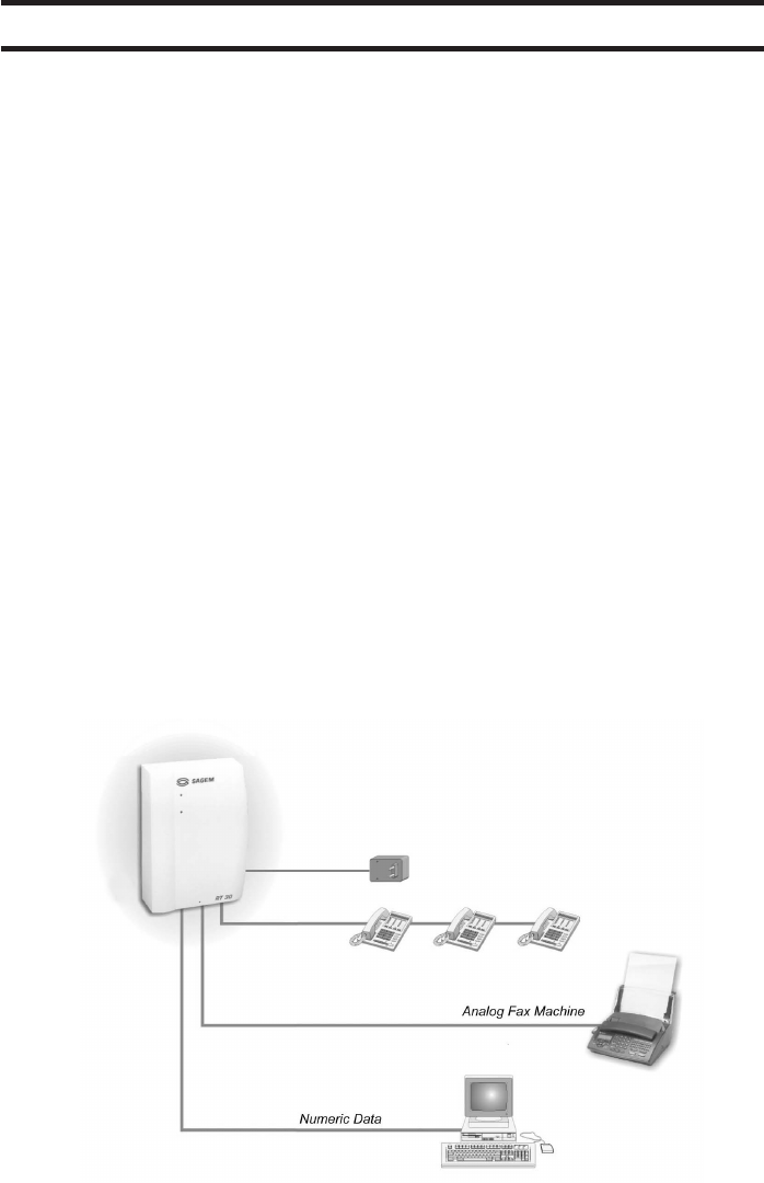
Your terminal connects the subscriber to the network over a radio link (GSM radio standard).
It is located on the subscriber’s premises and installed on the wall. The figure below
shows the possible connections of your terminal:
• 1 to 3 standard telephones
• Analog G3 fax machine
• Digital terminal (PC or fax machine)
• Power supply adapter
• External antenna, optional
• 2 screws and plugs for fixing the terminal on the wall.
ZAMBUUUJO.p65 10/04/02, 18:439
10 Your terminal - Description
YOUR TERMINAL
Connectors
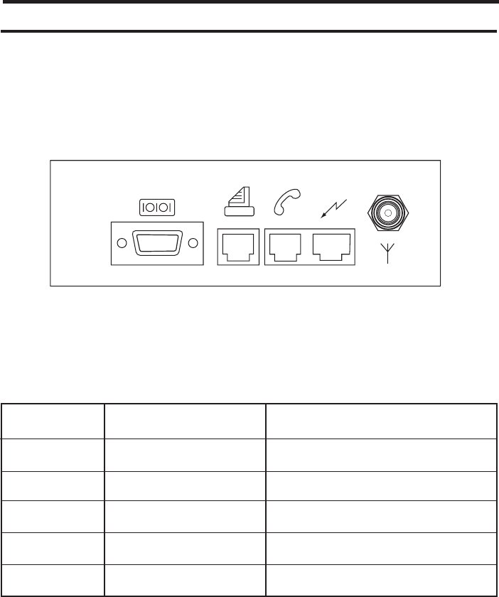
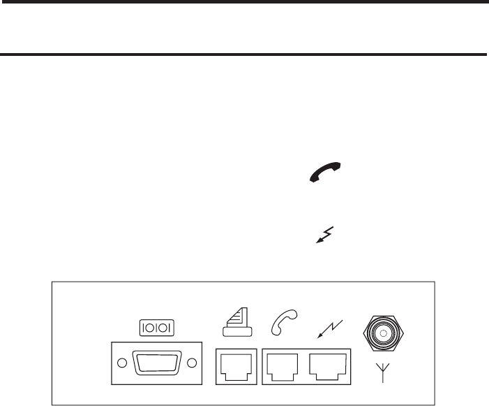
The figure below gives the location of each connector.
The table below gives the meaning of each connector.
Connector Type Connection for
J1 Data 9 points, RS232 PC or digital fax machine
J2 RJ11 female Fax machine
J3 RJ11 female Phone
J4 RJ45 female Power adapter
J5 TNC / BNC or mini UHF External antenna if needed
J1 J2 J3 J4 J5
ZAMBUUUJO.p65 10/04/02, 18:4410
11Your terminal - Description
YOUR TERMINAL
Lamps
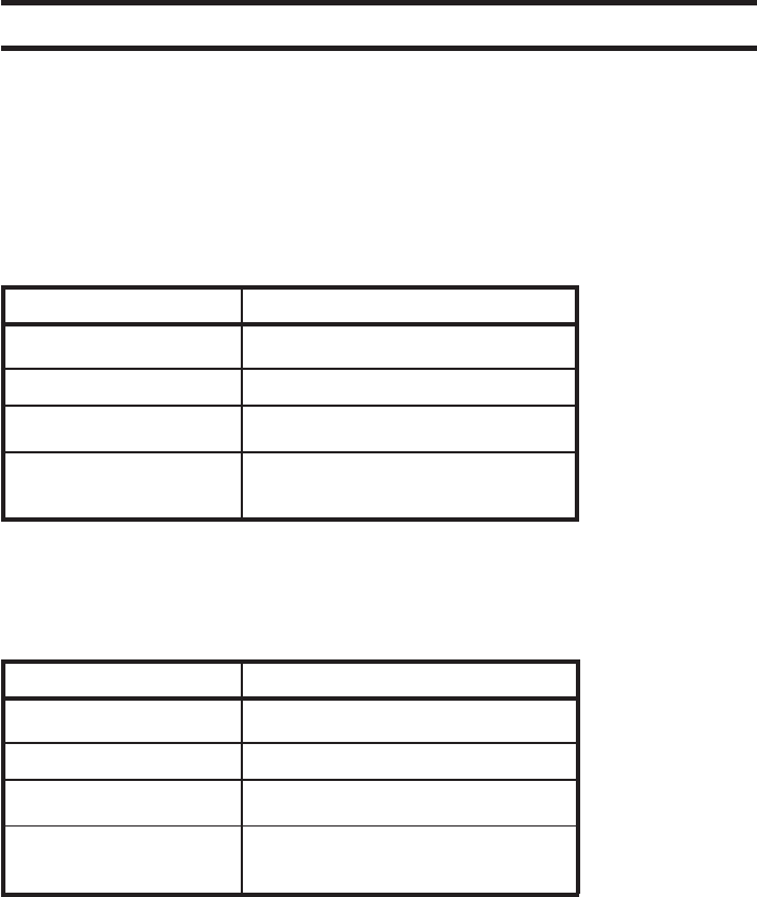
The tables below give the meaning of the 2 lamps on the front panel.
Upper lamp (red)
Lower lamp (green: operating with power supply, red: operating with backup battery,
depending on model)
Battery
A battery backup is integrated in your terminal, it is disconnected after the factory tests
and for storage. You are required to connect it.
With the battery, in case of mains failure your terminal works properly during 1 hour (talk
time) or 6 hours (stand-by).Dependent on operating conditions and network configuration.
Status Function
Off Power off
On Power on
Slow flashing Off hook
Rapid flashing SIM card missing or waiting for
PIN code entry
Status Function
Off Call forward inactive
On Call forward active
Slow flashing SMS or voice mail notification
Rapid flashing Searching network or
network not available
ZAMBUUUJO.p65 10/04/02, 18:4411
12
INSTALLING AND USING THE TERMINAL FOR THE
FIRST TIME
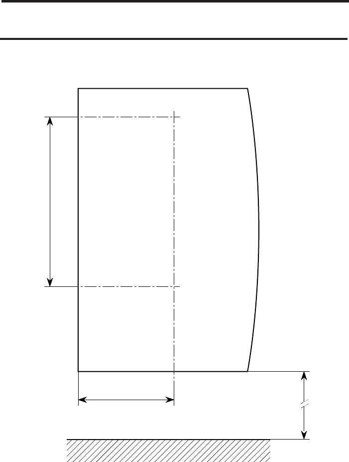
Installing your terminal
145
74.5
> 300
Dimensions in mm
ZAMBUUUJO.p65 10/04/02, 18:4412
13
Installing your terminal
INSTALLING AND USING THE TERMINAL FOR THE
FIRST TIME
Installing your terminal
Where should you install your terminal?
In order to prevent any interference between your terminal and other electrical
equipment in the immediate vicinity (phones, television sets, microcomputers, etc.),
which could result in extraneous noise, make sure that you install your terminal at a
distance of at least 2 m from any of these types of equipment.
However, if there is no sign of any interference, you can reduce this distance.
Distance between your phone and the terminal
Make sure that, when your phone is connected to the terminal, the distance
between them is at least 2 m. If you become aware of interference, move the phone
and its cord further away from the terminal, until the interference disappears.
Wall installation
Required tools
• One hammer drill + set of drills
• One 500 mm spirit level
• One flat blade screwdriver
• One 2-meter tape measure.
Procedure:
1. Mark out the positions of the fixing holes, either using the drilling template (part of
the packaging: cut it) or by marking two points 145 mm apart in a vertical line.
Vertical attachment 300 mm from the ground (terminal low point) (see Figure on
opposite page).
2. Check the vertical alignment of the points using the spirit level.
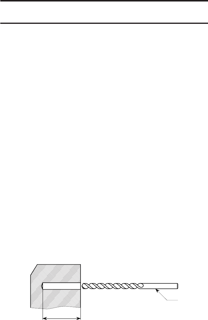
3. Drill to a diameter of 5 mm and a depth of 25 mm.
ÿ 5
25
ZAMBUUUJO.p65 10/04/02, 18:4413
14
INSTALLING AND USING THE TERMINAL FOR THE
FIRST TIME
4. Fit the expansion plug supplied with the terminal.
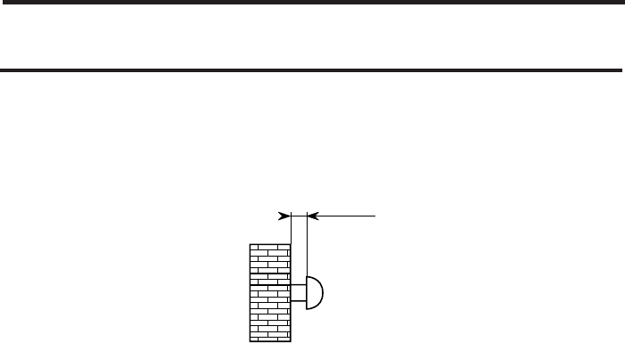
5. Insert the two screws in the plugs, leaving a 2.5 mm minimum space between
the wall and the screw head.
6. Offer up the backplate (the keyholes) to the two screwheads, position the
backpate on the screws and slide it down.
7. Moderatly tighten the bottom screw to prevent the terminal from becoming
detached.
For attachment on wood-type materials:
8. Prepare per steps 1 and 2.
9. Drill a 2 mm dia. 20 mm deep pilot hole.
10. Screw the two screws, leaving a 2.5 mm minimum space between the wall and
the screw head.
11. Carry out steps 6 and 7.
2.5 mm
Installing your terminal
ZAMBUUUJO.p65 10/04/02, 18:4514
15
INSTALLING AND USING THE TERMINAL FOR THE
FIRST TIME
This equipment has to be imperatively installed, tested and serviced by
qualified personnel. After installation or service, the cover must imperatively be closed
and fastened to base with the tie or the screw provided by the manufacturer, in order to
ensure end user safety against electric shocks.
No operator serviceable parts. Refer servicing to qualified personnel. To prevent electric
shocks, do not remove cover.
Connecting line / battery / power supply
The various accessories supplied have to be installed carefully before powering the
equipment.
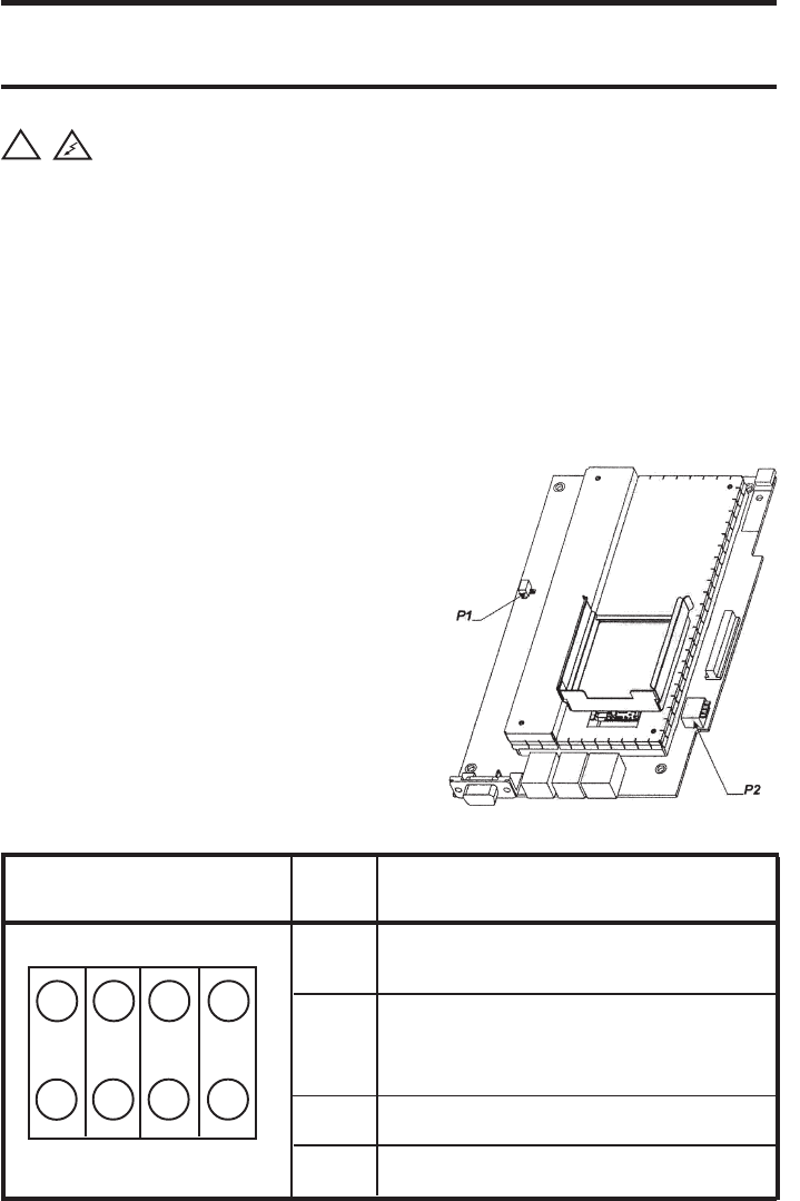
Configuration of P2 Point Position of the button
of P2
1 A: Internal antenna (Position by default)
B: External antenna
2 A: Power supply disabled
B: Power supply enable (Position for
operation)
3 Reserved
4 Reserved
A A A A
BB B B
1234
Configuration of the terminal
1. Disconnect the power supply.
2. Open the cover of the terminal.
3. Check if the battery is connected (the plug
must be inserted in connector P1).
4. If the battery is connected go to step 6.
5. Connect the wire connecting the battery
to connector P1, on the printed circuit
board of the terminal.
6. Configure DIP switch P2 as indicated in
figure below.
7. Close the cover of the terminal.
8. Fasten to the base with the tie or screw
provided.
Installing your terminal
!
ZAMBUUUJO.p65 10/04/02, 18:4515
16
Before connecting, read carefully safety instructions p3
Line
1. Connect your phone set to the other end of your phone cord.
2. Plug the phone cord into the RJ11connector J3 .
Power supply
1. Plug the power supply cable to the connector J4 .
2. Plug the other end of the power supply cable into a 230 V electrical socket outlet.
Commissioning
After having powered the terminal, you will see the lamps successively blinking as below
(it generally takes less than 1 minute, depending on network):
1. Both lamps on the front panel of the terminal flash alternatively to indicate that the
terminal is initializing.
2. At the end of initialization, both upper and lower lamps flash rapidly during
1 second.
3. If necessary, enter you PIN code as indicated in paragraph Your first call p13.
4. The lower lamp is on, meaning the terminal is ready to use.
Your terminal is now installed !
Check the signal strength.
You can now make your first calls !
INSTALLING AND USING THE TERMINAL FOR THE
FIRST TIME
Installing your terminal
J1 J2 J3 J4 J5
ZAMBUUUJO.p65 10/04/02, 18:4616

17
INSTALLING AND USING THE TERMINAL FOR THE
FIRST TIME
Check the field strength
The upper lamp on the terminal will flash rapidly if the field strength is incorrect or if
there is no connection to the phone network.
If necessary, connect an external antenna to the device. Move the external antenna to a
position where the coverage is at its maximum.
The external antenna should preferably be inside building to avoid overvoltages due to
lightning. If not, it is the responsability of installer to provide adequate overvoltage
protections on external antenna. The installation must be done by qualified personal.
Your first call
Note: In case of a problem at any step of the operations, you can re-initialize the
device and disconnecting the battery, wait for 1 minute and connect it again.
This operation should only be done by the qualified personnel.
Making your first call
1. Lift the handset; il you hear a 2 bip/second tone in the handset, enter your PIN
code and validate using #. This action is only done when you use your terminal
for the first time. You should hear a continuous dialling tone inviting you to dial
and the lower lamp on your terminal should be blinking.
2. You can then proceed as if you were using a conventional fixed phone.
3. When you replace the handset, the lower lamp stops blinking.
Receiving calls
1. When you receive a call, your phone rings (activation by the terminal).
2. When you lift the handset, the lower lamp blinks slowly.
3. You can speak to the caller.
Your first call
ZAMBUUUJO.p65 10/04/02, 18:4617

18
SERVICES AVAILABLE ON THE TERMINAL
Conference calls
Conference calls *
To manage conference calls, use the R button on your handset as indicated below:
3-party conference call
This service allows you to speak to several persons at the same time.
To set up a Conference call :
1. Dial the first party number. You are then in conversation with him (Mr X).
2. Press R then 2 on the phone to put Mr X on hold.
3. Dial the second party number (Mr Y). He comes on the line.
4. Press R followed by 3 to be connected with both Mr X and Mr Y.
Note: If you replace your handset, all calls are released.
You can also set up a Conference Call if you are already in conversation and you receive
a call waiting tone :
1. Press R then 2 on the phone to put the first conversation on hold and to activate
the waiting call. You can now speak to the second party.
2. Press R then 3 on the phone to be in 3-party conference call.
ZAMBUUUJO.p65 10/04/02, 18:4618
19Double call / Answering device
Double call (Call hold / Call wait) *
Using the “double call” service, you can converse with two callers alternatively. If you are
engaged on a “double call” and a third caller wishes to contact you, he will then be directed
to your voice messaging service*, where he can leave a message for you.
You are engaged on a call with Mr X and a second caller Mr Y rings you; this is indicated
to you by a call waiting tone.
You then have three options:
Button pressed Meaning
R followed by 2Current call put on hold and activation of the waiting call
R followed by 0Rejection of the call on hold or of the waiting call
R followed by 1Terminate the current call and switch to the call on hold
or to the waiting call
You can accept the new call
1. Press R followed by 2. Mr X is put the on hold. Mr Y will come on the line.
2. To switch from one call to another, press R then 2.
3. To terminate the calls, replace the handset.
You can terminate your first call and accept the call on hold
1. Press R followed by 1.
You can reject the new call in order to stay on the line to your first caller
1. Press R then 0.
Answering device *
The terminal is not equipped with an answering device. However, it manages the
messaging service provided by the network Operators*.
With the answering device activated (by means of call forwards to your voice mail), none
of the calls are lost and your caller is always able to leave a message for you.
If a message has been left, this is indicated by a shrill beep in the phone and the upper
lamp flashing slowly on the front of your terminal.
SERVICES AVAILABLE ON THE TERMINAL
ZAMBUUUJO.p65 10/04/02, 18:4619

20 Call forwarding / Fax application
Type Interrogation Activation Deactivation
Unconditional (CFU) *#21# **21* <Number> # ##21#
Busy (CFB) *#67# **67* <Number> # ##67#
No reply (CFNRy) *#61# **61* <Number> # ##61#
Network problem *#62# **62* <Number> # ##62#
(unavailable)
(CFNRE - not reachable)
SERVICES AVAILABLE ON THE TERMINAL
Result of interrogation:
bass beep: service not activated
shrill beep: service activated
Fax application *
• Plug your analog fax machine (G3) into the RJ11 connector J2. The fax line is
dedicated only to send or receive fax.
Receive
• When you receive a fax call, only the fax machine rings (the phones connected to
the J3 connector does not ring).
• During the fax call, the phone line is not available.
Transmit
• When you send a fax, the phone line is not available.
Call forwarding *
Setting up call forwards enables you to switch the incoming calls to another phone
number. This number can be the Network voice mail number or any number, provided
the subscription allows it (*).
Several types of call forwarding are available:
•Unconditional call forwarding (all incoming calls are forwarded to the number
recorded).
•Call forwarding, busy (engaged) (when you are engaged in a call, and somebody
else tries to call you, his call is directly forwarded to the number recorded).
•Call forwarding, no reply (when you are not at home or you do not answer, the
incoming call is forwarded to the number recorded).
•Call forwarding, network problem (if the terminal is not reachable the incoming
calls are directly forwarded to the number recorded).
ZAMBUUUJO.p65 10/04/02, 18:4620
21
SERVICES AVAILABLE ON THE TERMINAL
Data application
Data application *
Cable installation
A cable (in option) allows you to connect your terminal directly via the DB 9 pts plug to
the serial port on a computer (RS232 - V24).
Modem installation
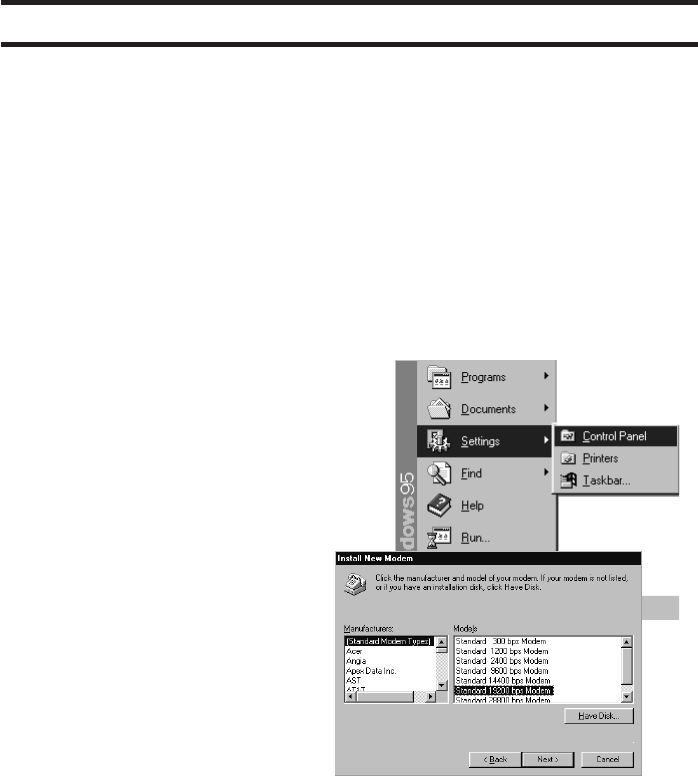
- Driver installation for Windows™ 95/98
• Click on Start, at the bottom left of
the screen, then without releasing the
mouse button, select Settings >
Control Panel.
• In the window which is displayed,
double-click on the Modems icon:
the Modems Properties window is
displayed. Click on Add: the Install
New Modem window appears.
Check the Don’t detect my modem
box and click on Next >.
If a modem is already installed, the
Modems Properties window is
displayed: click on Add, the Install
New Modem window is displayed.
• In the new window, click on Standard
Modem Types in the left hand
column and on Standard 19200 bps
Modem in the right hand column,
then click on Next >.
• In the new window, select the port to
which the phone is connected: e.g.
Communications Port (COM1),
then click on Next >.
• The computer installs the driver and
a success message is displayed.
Click on Finish then on Close in the
Modems Properties windows.
Installation is completed.
ZAMBUUUJO.p65 10/04/02, 18:4621
22 Data application
SERVICES AVAILABLE ON THE TERMINAL
- HyperTerminal installation for Windows™ 95/98
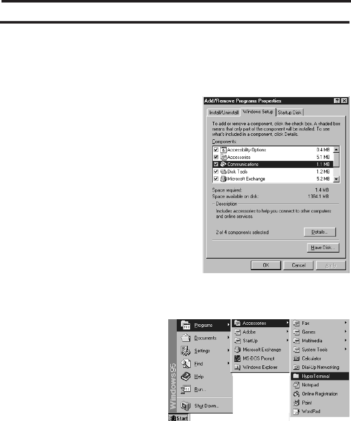
• From the Control Panel, double-click
on the Add/Remove Programs icon.
In the new window, click on
Windows Setup, then double-click
on Communications.
• In the new window, check the Dial-
Up Networking and HyperTerminal
boxes, then click on OK; click on OK.
Installation is completed.
- HyperTerminal configuration
HyperTerminal allows you to transfer files to or from a remote PC equipped with a
modem.
• Click on Start, then without
releasing the mouse button,
select Programs >
Accessories > HyperTerminal
or Programs > Accessories >
Communications >
HyperTerminal.
• In the HyperTerminal window,
double-click on the HyperTerminal
icon to run the application. The New
Connection, Connection
Description windows appear. Enter
a name (File transfer, for example),
the choice of associated icon is
unimportant. Click on OK.
ZAMBUUUJO.p65 10/04/02, 18:4622
23Data application
SERVICES AVAILABLE ON THE TERMINAL
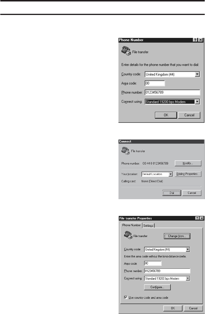
• In the new window, the name chosen
and the associated icon are
displayed. Select Standard 19200
bps Modem then enter the phone
number. Click on OK.
• In the new window, click on Modify…
The File transfer Properties window
appears.
If you do not want to Use country
code and area code, suppress the
tick in the box.
• Click on Configure…
ZAMBUUUJO.p65 10/04/02, 18:4623
24 Data application
SERVICES AVAILABLE ON THE TERMINAL
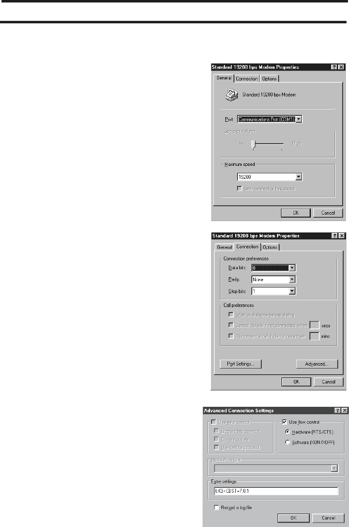
In the new window, check if the
parameters are correct (COM1,
19200). Click on Connection.
• Fill in the window as follows:
Data bits : 8
Parity : None
Stop bits : 1
• Click on Advanced… and fill in the
window as follows:
• Tick the box Use flow control for
Hardware.
Extra settings: &K3+CBST=7,0,1
• To close, click on OK, OK, OK,
Cancel.
Save under the chosen name (File
transfer, for example)
K4
ZAMBUUUJO.p65 10/04/02, 18:4624
25Data application
SERVICES AVAILABLE ON THE TERMINAL
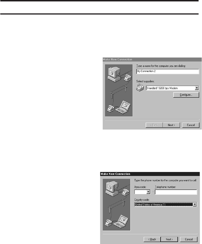
Internet application
Parameter configuration in the computer
To log onto the Internet from your PC,
you will have to set up a «Dial-Up
Networking» connection.
To do this, go to My Computer/Dial-
Up Networking and select Make New
Connection.
Give your connection a name and
select Standard 19200 bps Modem
(*).
Click on Configure… and check that
the parameters are as follows:
Maximum speed : 19200
Data bits : 8
Parity : None
Stop bit : 1
Flow control : hardware
Additional parameters : &K3+CBST=7,0,1
Then click on Next.
Enter the phone number of your
Internet service provider. Click on
Next and confirm by clicking on
Finish.
To access the Internet, start up your
Dial-Up Networking connection; you
must then enter the user name and
the password. When the connection
is established, start up your browser.
(*) If the Standard 19200 bps Modem is not in the list, click on Cancel then refer to the
chapter entitled MODEM INSTALLATION to install it.
ZAMBUUUJO.p65 10/04/02, 18:4625
26 Data application
SERVICES AVAILABLE ON THE TERMINAL
Special cases
Some service providers automatically create a Dial-Up Networking connection for
certain types of modems when the Internet browser is being installed. You are advised
to choose a Standard 19200 bps Modem type connection.
If this is not available, select any connection. When the browser has been installed,
go to My Computer/Dial-Up Networking and open the connection corresponding to
your service provider. Then, change the parameters as shown in the previous section.
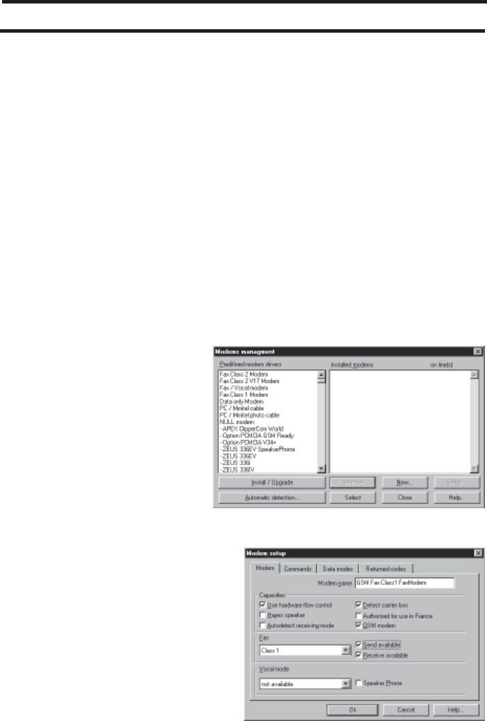
Fax application
• Using RTE FOTOWIN
• Start the application.
• Click on Setup: the window Line
Setup appears. Click on Modem
to create a new modem.
• Click on New and fill the Modem
tab as follows:
ZAMBUUUJO.p65 10/04/02, 18:4626
27
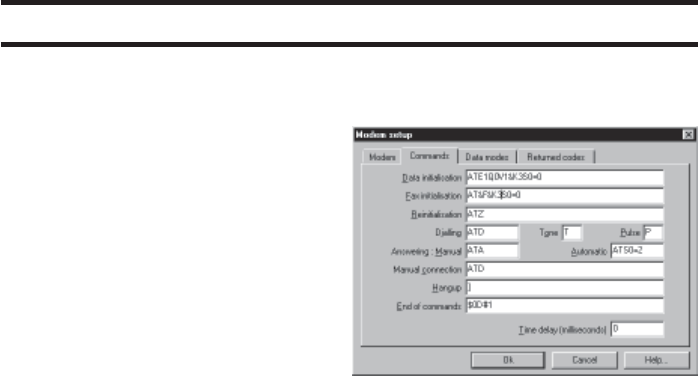
• Select the Command tab and fill it
as follows:
• Click on OK then on Close to
return to the window Line setup.
Select the modem created and the
serial port wanted then click on
OK.
• The application initializes the
modem and goes into waiting
state.
AT commands
Notation [-] = optional parameter
The following AT commands are handled by the phone:
ATE[0|1]<CR> Command echo:
0= off
1= on.
ATV[0|1]<CR> Answers to AT commands:
0= digital format
1= text format.
ATQ[0|1]<CR> 0= Answers to AT commands are sent to the computer.
1= Answers to AT commands are not sent to the computer.
ATD<number>[;]<CR>
or
ATDP<number>[;]<CR> Dialing.
or
ATDT<number>[;]<CR>
The characters for: ‘P’ or ‘p’ (pulse), ‘T’ or ‘t’ (tone), ‘W’ or ‘w’ (wait), ‘,’
(pause) are accepted and indifferent.
«;» at the end of the command, before <CR>, means: phone call (as
opposed to data call).
Data application
SERVICES AVAILABLE ON THE TERMINAL
ZAMBUUUJO.p65 10/04/02, 18:4627

28 Data application
SERVICES AVAILABLE ON THE TERMINAL
ATA<CR> Answer a call.
ATH[0]<CR> Disconnect existing link.
ATS0=i<CR> Answer calls after ”n“ rings.
i = 0: no automatic off-hook.
ATBi<CR> Data rate selection:
ATB7 : Analogue modem 2400 (V22BIS)
ATB11 : Analogue modem 4800 (V32)
ATB13 : Analogue modem 9600 (V32)
ATB25 : UDI 2400 - ISDN call
ATB27 : UDI 4800 - ISDN call
ATB29 : UDI 9600 - ISDN call.
AT\N4<CR>
or RLP.
AT\N6<CR>
AT\N0<CR> Non RLP.
A/ Repetition of the previous line.
During a data call:
+++ Return to command mode (Allows to hang up using ATH as soon as
the modem has sent OK).
Note: The commands may be combined:
For example
ATE0V0<CR>
ATV0E0<CR>
ATE0<CR> then ATV0<CR>
are equivalent.
ZAMBUUUJO.p65 10/04/02, 18:4628

29
Depending on model, the following commands are available:
AT&F To recover the default setting.
AT&kn Flow control
n = 0: no flow control
n = 3: hardware flow control (RTS/CTS)
n = 4: software flow control (XON/XOFF)
AT&W Writes the user configuration in saved memory. ATZ command initializes
the phone with this configuration.
AT&V Gives the current configuration, the user configuration and the default
settings.
For example
AT&V
ACTIVE PROFILE:
B29E0 Q0 V1 \N0\V0+CMFG1
S00:001 S07:000
STORED PROFILE:
B13E1 Q1 V1 \N4\V1+CMFG0
S00:000 S07:000
DEFAULT SETTINGS:
B11E1 Q0 V1 \V4\V0+CMFG0
S00:000 S07:000
OK
ATI0 to 9 ATI commands give information about the model, type, software version,
etc.
Data application
SERVICES AVAILABLE ON THE TERMINAL
ZAMBUUUJO.p65 10/04/02, 18:4629

30 Data application
SERVICES AVAILABLE ON THE TERMINAL
Your questions answered
This section describes the most common problems encountered whilst installing data
transmission systems.
The terminal does not respond to the AT commands:
- Check that your HyperTerminal session parameters are correct.
- Check that your cable is connected.
- Check that you are connected to the correct COM port on your PC. To ensure that this
is the case, use an HyperTerminal session described previously.
The modem must respond to the AT commands. Example : type ATZ then <Enter>.
The modem responds OK.
The terminal responds to the AT commands. It dials, then cuts off immediately:
- Check that your terminal supports the DTR signal. If not, type the following commands:
at&d0 and at&w.
- If your terminal supports the DTR signal, check the condition of your cable.
- Check that a DATA type option is available with your subscription.
Special characters appears on your PC screen during an incoming call:
- Change the speed of the serial link on your computer so that it corresponds to the
speed of your terminal.
ZAMBUUUJO.p65 10/04/02, 18:4630

31
ADVICE IN THE EVENT OF A PROBLEM
Advice in the event of a problem
Before contacting the Customer Service Department, you can try and identify the problem
with the aid of the following checklist:
Total lack of response from the terminal
• Check that the phone is connected to the terminal.
• Check that the terminal is connected to the mains power supply, check the socket
outlet and the connecting cable.
• Check the field strength (see page 12).
Interruptions during a call
• Check the field strength (see page 12).
Tone errors
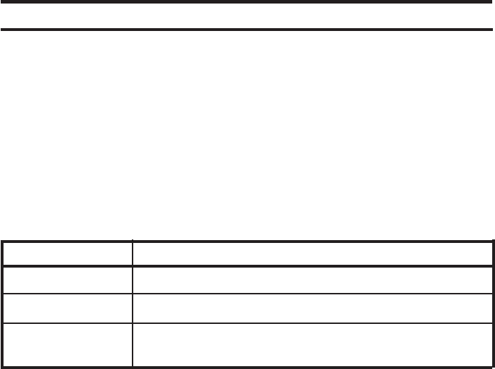
Tone and sound Explanation Action
------- continuous beeps No SIM card or auto
SIM code pin loading
Humming in the Interference between Move them at least
handset your phone and the 2 metres apart
terminal
Loud tone and busy tone No network available Change the position
after the number has been of the terminal or check
dialled and upper lamp subscription
rapidly flashing
No sound If after hang off during Wait and try again
15 seconds, there may
be a temporary fault on
the phone network
Your caller cannot hear The field strength is Change installing position
you too weak
You cannot hear The terminal may be Disconnect the terminal
anything when you lift disconnected from the completely then reconnect
the handset mains power supply it and check the lamps
ZAMBUUUJO.p65 10/04/02, 18:4631
32
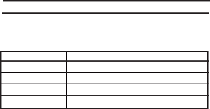
Generated tones
Type Values
Dial tone 425 Hz continuous for 15 seconds
Congestion / busy tone 425 Hz intermittent Ton: 300 ms / Toff: 300 ms
Confirmation beep 950 Hz, Ton: 100 ms
Abort beep 300 Hz, Ton: 100 ms / Toff: 500 ms /Ton: 100 ms
Note: The tones may leave different characteristics according to versions.
1 beep of confirmation: active service or OK
1 beep of abort: inactive service
2 beeps of abort: errors
When a signal indicating that the phone network is unavailable is received, the engaged
(busy) signal is transmitted down the line in place of the dialling tone.
If you lift the receiver when the PIN code has not been validated, a series of beeps is
superimposed over the dialling tone.
In every case, access to the emergency service is still possible.
ADVICE IN THE EVENT OF A PROBLEM
Advice in the event of a problem
ZAMBUUUJO.p65 10/04/02, 18:4632