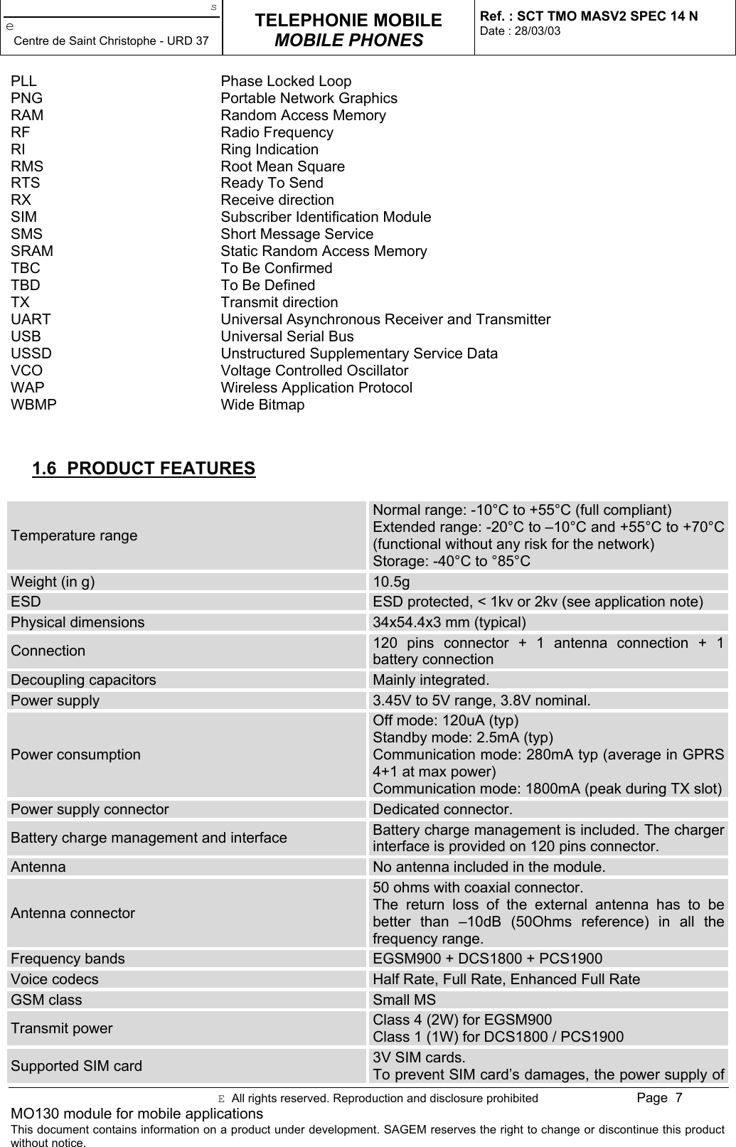
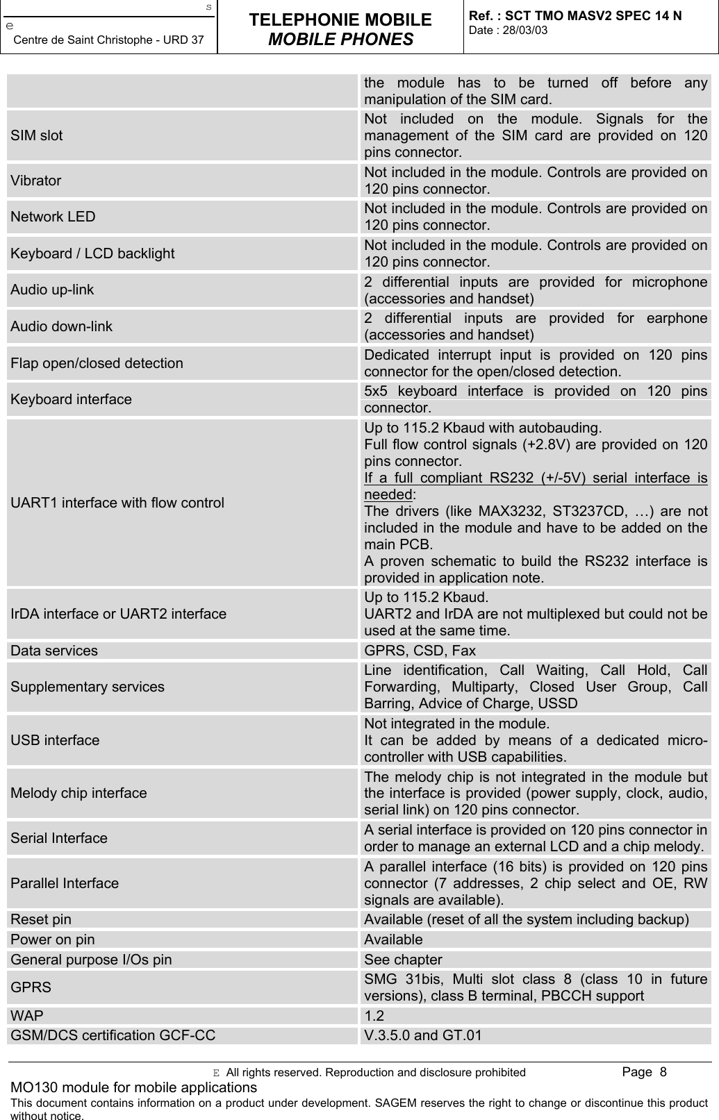
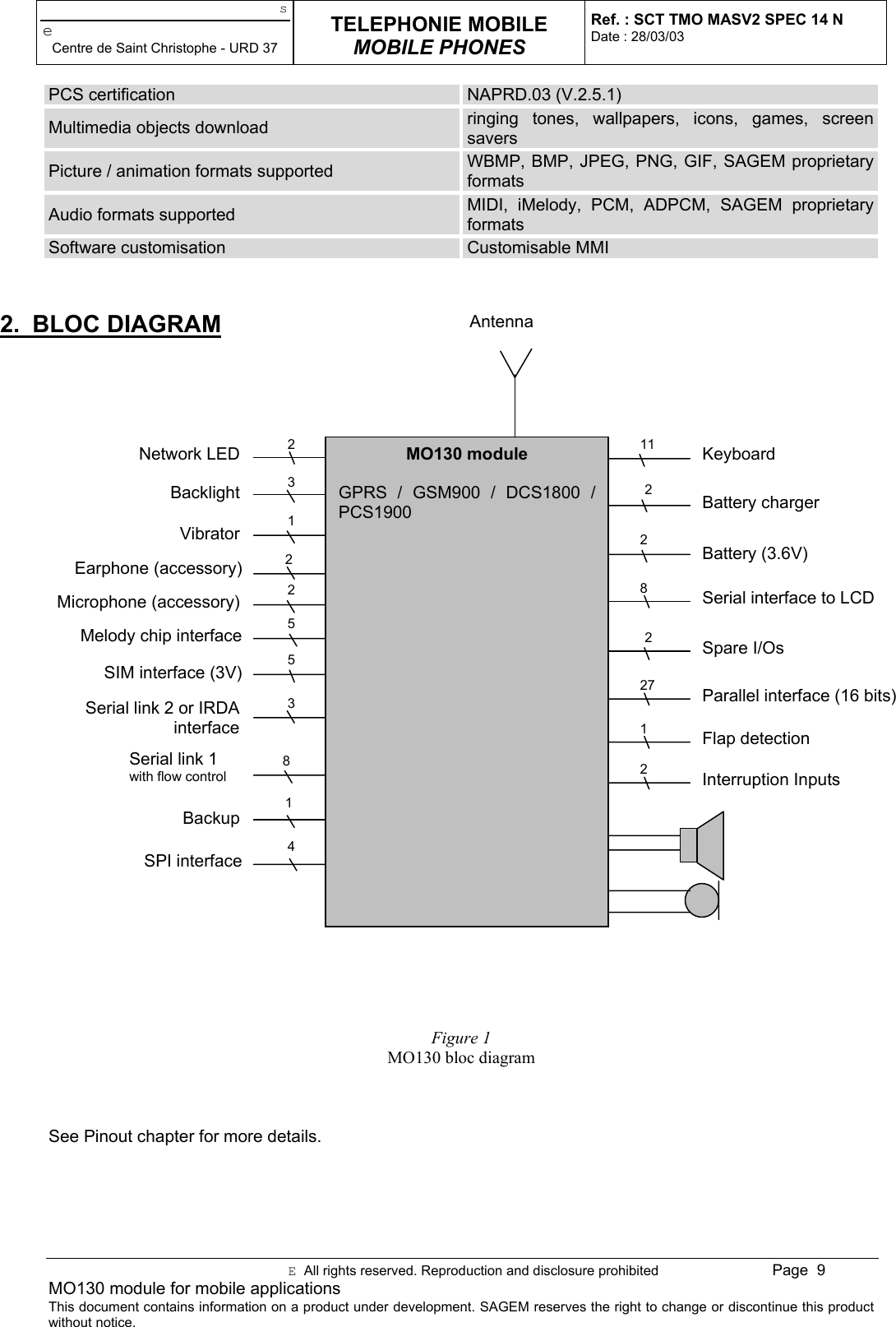
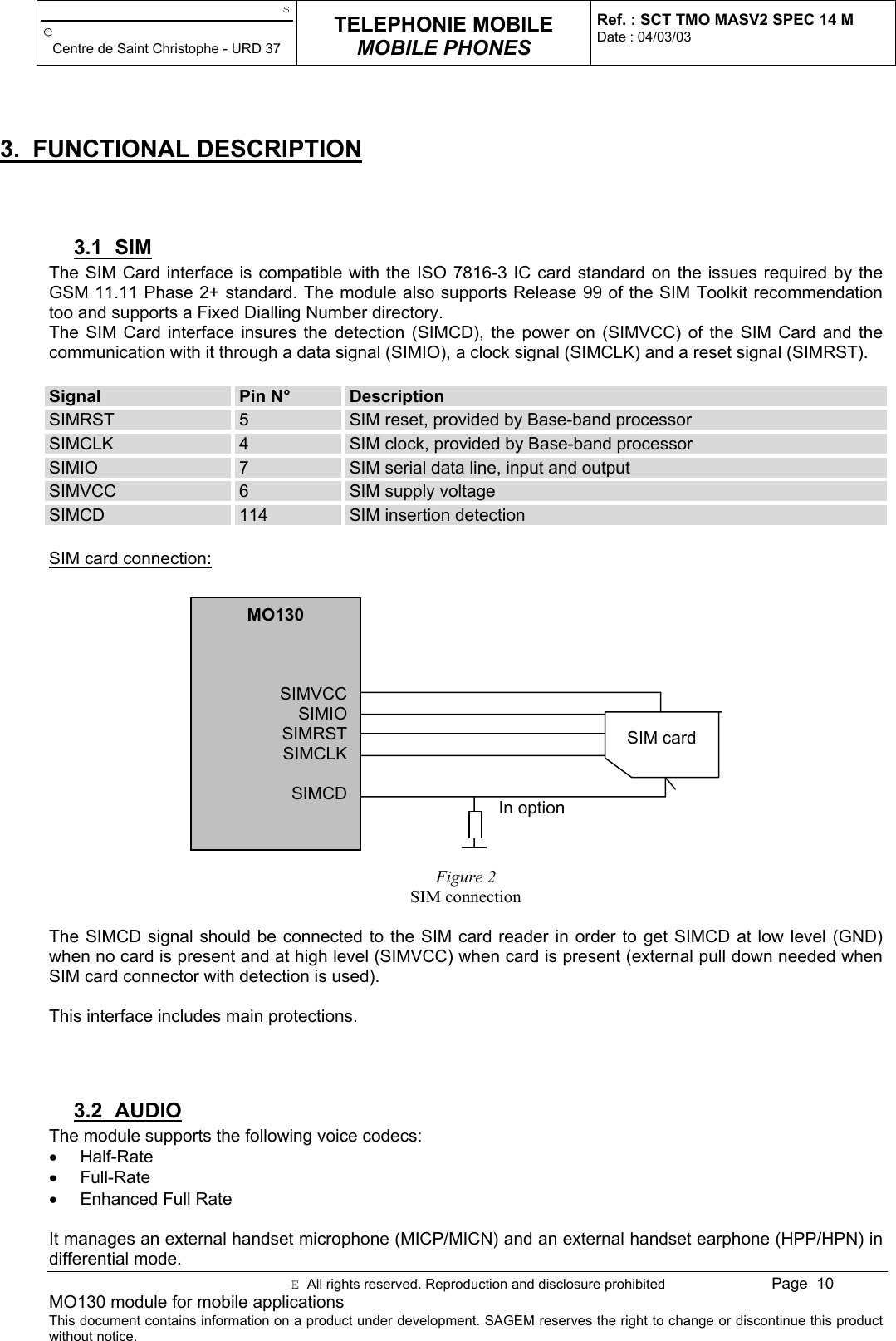
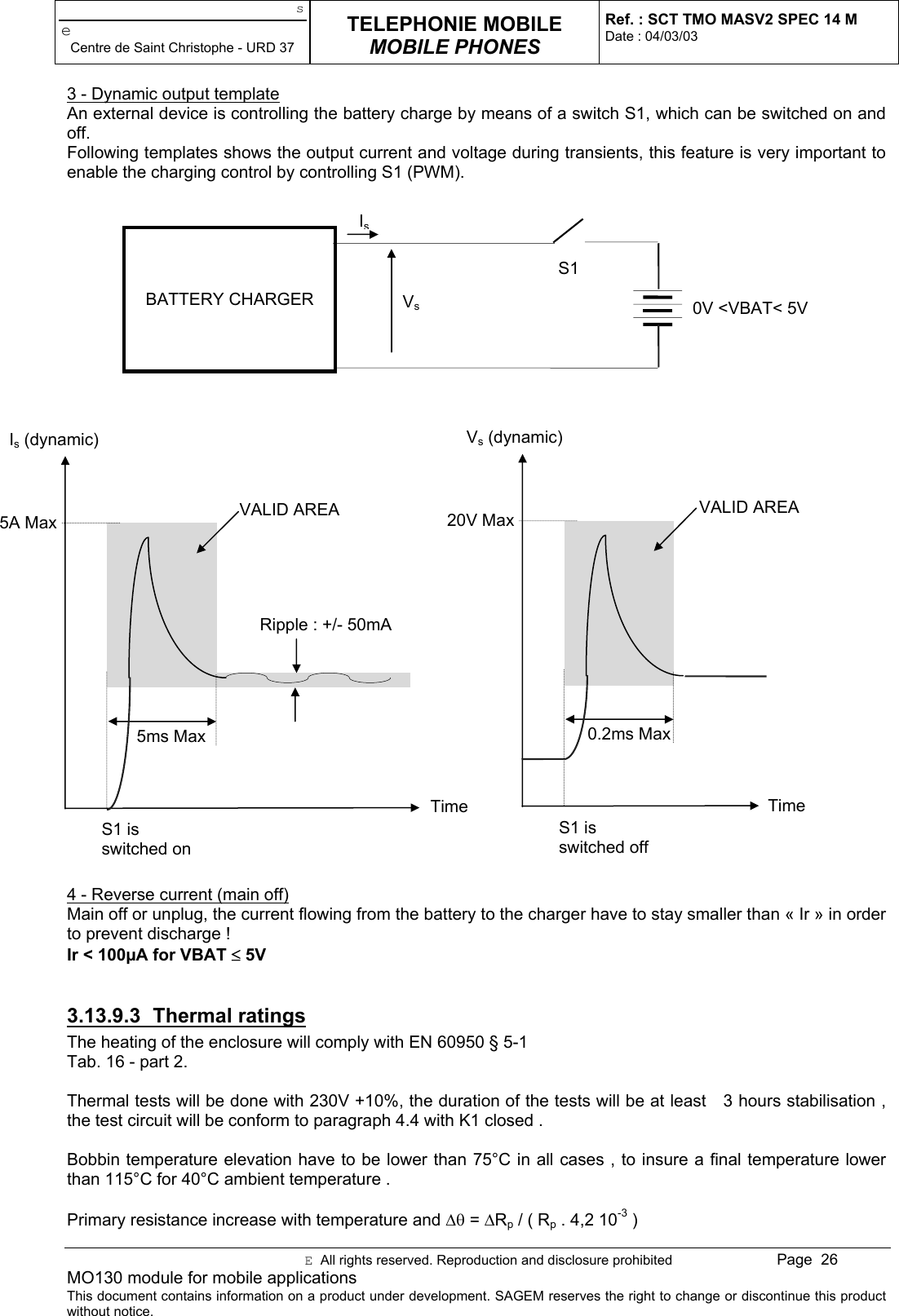
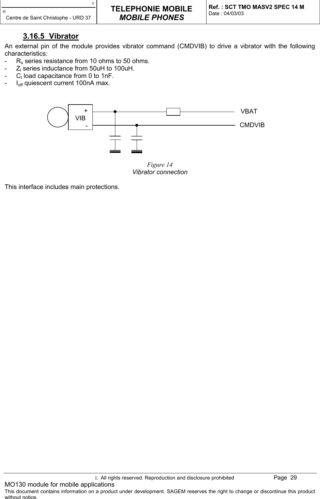
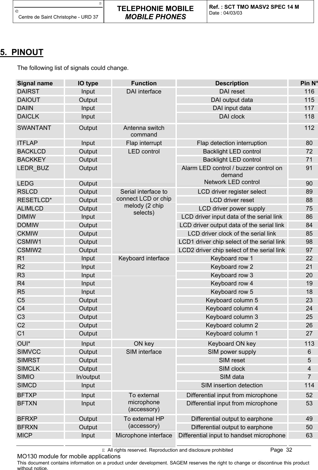
Sagem Wireless 95MASV2C Transmitter module for mobile applications User Manual SCT TMO MASV2 SPEC 14 N1

Sagem Wireless Transmitter module for mobile applications SCT TMO MASV2 SPEC 14 N1

Users Manual

seCentre de Saint Christophe - URD 37TELEPHONIE MOBILEMOBILE PHONESRef. : SCT TMO MASV2 SPEC 14 MDate : 04/03/03E  All rights reserved. Reproduction and disclosure prohibited Page  1MO130 module for mobile applicationsThis document contains information on a product under development. SAGEM reserves the right to change or discontinue this productwithout notice.MO130 MODULE FORMOBILE APPLICATIONSPREADING:Company Name Original Copies 1stpageSAGEM SA / SCT F. ROMAOO. HOLINT. GLASSONF. BULTEAUP. CAILLETF. HADDEDR. PATINECP. RATAJCZYKE. SOUBRANEJC. SURBONR. CRITONT. FEIXC. LABAUMEA. SEVENSJM. ROBERTM. BAPSERESR. ALLIOTD. QUIQUEREZP. QUENTING. BADUELA. LAFOURCADESecretariat 38 (Archive)CONCLUSION OR SUMMARY  :This document gives an overview of the MO130 module: a miniature, single-side board, tri-band GSM/GPRSmodule, ready for integration in mobile application like vehicle-mounted or vending machines…It describes the main functionalities of this module as well as the electrical interfaces, the mechanicalspecification (dimension, form…) and the electrical specification of the module.APPROBATION :Writer Project manager IPDEName : E. SOUBRANE T. GLASSON O. HOLINDate : 28/03/03 28/03/03 28/03/03Signature :
seCentre de Saint Christophe - URD 37TELEPHONIE MOBILEMOBILE PHONESRef. : SCT TMO MASV2 SPEC 14 MDate : 04/03/03E  All rights reserved. Reproduction and disclosure prohibited Page  2MO130 module for mobile applicationsThis document contains information on a product under development. SAGEM reserves the right to change or discontinue this productwithout notice.
seCentre de Saint Christophe - URD 37TELEPHONIE MOBILEMOBILE PHONESRef. : SCT TMO MASV2 SPEC 14 NDate : 28/03/03E  All rights reserved. Reproduction and disclosure prohibited Page  1MO130 module for mobile applicationsThis document contains information on a product under development. SAGEM reserves the right to change or discontinue this productwithout notice.MO130 MODULEFOR MOBILE APPLICATION
seCentre de Saint Christophe - URD 37TELEPHONIE MOBILEMOBILE PHONESRef. : SCT TMO MASV2 SPEC 14 NDate : 28/03/03E  All rights reserved. Reproduction and disclosure prohibited Page  2MO130 module for mobile applicationsThis document contains information on a product under development. SAGEM reserves the right to change or discontinue this productwithout notice.REVISIONSVersion Date Writer SubjectA 17/01/02 E. Soubrane Document creationB 25/02/02 E. Soubrane Modification: 120 pin connector pinoutC 02/05/02 E. Soubrane Modification: Battery connector pinout and functioningmodes description, consumptionD 11/08/02 E. Soubrane Pinout modifications, sensitivity, audio.E 28/06/02 E. Soubrane V56, sensitivityF 23/07/02 E. Soubrane DTR, DSR modificationG 06/09/02 E. Soubrane LEDs connection precision, mechanical dimensionprecision, maximum capacitance on parallel busH 13/09/02 E. Soubrane VBACKUP, IO description, SIMCDI 14/11/02 E. Soubrane BACKLCD/BACKKEY, Battery connectorJ 06/01/03 E. Soubrane /T. GlassonIO description precision, mechanical scheme update,humidity constraints. Compliance with FCCguidelines, GCF-CC (V.3.5.0)K 06/02/03 E. Soubrane Reset input level, V56 voltage in OFF modeL 11/02/03 T. Glasson Certification procedure warningsM 04/03/03 E. Soubrane VBAT maxN 28/03/03 T. Glasson Certification clarifications
seCentre de Saint Christophe - URD 37TELEPHONIE MOBILEMOBILE PHONESRef. : SCT TMO MASV2 SPEC 14 NDate : 28/03/03E  All rights reserved. Reproduction and disclosure prohibited Page  3MO130 module for mobile applicationsThis document contains information on a product under development. SAGEM reserves the right to change or discontinue this productwithout notice.INDEX1. OVERVIEW................................................................................................................................................................. 51.1 OBJECT OF THE DOCUMENT................................................................................................................. 51.2 REFERENCE DOCUMENTS..................................................................................................................... 51.3 STANDARDS COMPLIANCE .................................................................................................................... 51.4 COMPLIANCE WITH FCC GUIDELINES .................................................................................................. 61.5 TERMS AND ABBREVIATION .................................................................................................................. 61.6 PRODUCT FEATURES ............................................................................................................................. 7BLOC DIAGRAM................................................................................................................................................................. 93. FUNCTIONAL DESCRIPTION.................................................................................................................................. 103.1 SIM .......................................................................................................................................................... 103.2 AUDIO ..................................................................................................................................................... 103.3 DISPLAY.................................................................................................................................................. 113.4 PARALLEL INTERFACE ......................................................................................................................... 123.5 SPI INTERFACE...................................................................................................................................... 153.6 DATA ....................................................................................................................................................... 163.6.1 Data services .......................................................................................................................... 163.6.2 IrDA......................................................................................................................................... 163.6.3 UART 2 ................................................................................................................................... 163.6.4 V24 ......................................................................................................................................... 163.7 MULTIMEDIA........................................................................................................................................... 163.8 MELODIES GENERATION...................................................................................................................... 173.9 ANTENNA................................................................................................................................................ 173.10 KEYPAD .................................................................................................................................................. 193.11 DAI........................................................................................................................................................... 193.12 CLOCKS .................................................................................................................................................. 193.13 POWER MANAGEMENT AND CHARGE................................................................................................ 203.13.1 Battery..................................................................................................................................... 203.13.2 VRDBB.................................................................................................................................... 203.13.3 VRDBBDC .............................................................................................................................. 203.13.4 VRIO ....................................................................................................................................... 203.13.5 V56 ......................................................................................................................................... 203.13.6 Vbackup.................................................................................................................................. 203.13.7 Charge .................................................................................................................................... 213.13.8 AC/DC switching charger........................................................................................................ 223.13.8.1 Operating temperature............................................................................................................................................223.13.8.2 Electrical ratings.....................................................................................................................................................223.13.8.3 Thermal ratings ......................................................................................................................................................233.13.9 Simple battery charger............................................................................................................ 233.13.9.1 Operating temperature............................................................................................................................................233.13.9.2 Electrical ratings.....................................................................................................................................................243.13.9.3 Thermal ratings ......................................................................................................................................................263.14 ACCESSORIES....................................................................................................................................... 273.15 MANUFACTURER MMI CUSTOMIZATION ............................................................................................ 273.16 OTHER FUNCTIONS .............................................................................................................................. 273.16.1 Flap......................................................................................................................................... 273.16.2 Buzzer..................................................................................................................................... 273.16.3 Backlight ................................................................................................................................. 273.16.3.1 Red or Green LEDs ................................................................................................................................................273.16.3.2 Blue and White LEDs.............................................................................................................................................283.16.3.3 Multicolour LEDs and EL film ..............................................................................................................................283.16.4 Network LED........................................................................................................................... 283.16.5 Vibrator ................................................................................................................................... 294. OPERATING MODES............................................................................................................................................... 304.1 MODES DESCRIPTION .......................................................................................................................... 304.1.1 No supply................................................................................................................................ 304.1.2 OFF......................................................................................................................................... 304.1.3 Active ...................................................................................................................................... 304.1.4 Standby................................................................................................................................... 304.2 TRANSITIONS DESCRIPTION ............................................................................................................... 31
seCentre de Saint Christophe - URD 37TELEPHONIE MOBILEMOBILE PHONESRef. : SCT TMO MASV2 SPEC 14 NDate : 28/03/03E  All rights reserved. Reproduction and disclosure prohibited Page  4MO130 module for mobile applicationsThis document contains information on a product under development. SAGEM reserves the right to change or discontinue this productwithout notice.4.2.1 Power_on................................................................................................................................ 314.2.2 Power_off................................................................................................................................ 314.2.3 Switch_on ............................................................................................................................... 314.2.4 Switch_off ............................................................................................................................... 314.2.5 Wake up.................................................................................................................................. 315. PINOUT .................................................................................................................................................................... 326. ELECTRICAL SPECIFICATION................................................................................................................................ 356.1 VBAT ....................................................................................................................................................... 356.2 POWER SUPPLIES................................................................................................................................. 366.2.1 VRDBB (120 pin connector, pin 3) .......................................................................................... 366.2.2 VRIO (120 pin connector, pin 2).............................................................................................. 366.2.3 V56 (120 pin connector, pin 74) .............................................................................................. 366.2.4 ALIMLCD (120 pin connector, pin 75)..................................................................................... 376.3 DAI INTERFACE...................................................................................................................................... 386.4 NETWORK LED....................................................................................................................................... 386.5 BACKLIGHT ............................................................................................................................................ 386.6 SERIAL INTERFACE FOR LCD .............................................................................................................. 386.7 KEYBOARD INTERFACE........................................................................................................................ 396.8 VIBRATOR CONTROL ............................................................................................................................ 396.9 V24 .......................................................................................................................................................... 396.10 IRDA ........................................................................................................................................................ 396.11 CHARGER............................................................................................................................................... 396.12 RESET..................................................................................................................................................... 406.13 SPARE IO................................................................................................................................................ 406.14 CLOCKS .................................................................................................................................................. 406.15 PARALLEL INTERFACE ......................................................................................................................... 406.16 JTAG INTERFACE .................................................................................................................................. 416.17 DAC ......................................................................................................................................................... 416.18 ADC ......................................................................................................................................................... 416.19 INTERRUPTS .......................................................................................................................................... 416.20 VBACKUP................................................................................................................................................ 427. ENVIRONMENTAL SPECIFICATION....................................................................................................................... 427.1 OPERATING CONDITIONS .................................................................................................................... 427.2 CLIMATIC CONDITIONS......................................................................................................................... 428. MECHANICAL SPECIFICATION WITH CONNECTOR ............................................................................................ 439. INTEGRATION.......................................................................................................................................................... 469.1 120 PINS CONNECTOR ......................................................................................................................... 469.1.1 MO130 connector ................................................................................................................... 469.1.2 Mother board connector.......................................................................................................... 479.2 MO130 ANTENNA CONNECTOR ........................................................................................................... 489.3 BATTERY CONNECTOR ........................................................................................................................ 49ANNEXE 1 : REFERENCE SENSITIVITY LEVEL ............................................................................................................ 50ANNEXE 2 : IO DESCRIPTION ........................................................................................................................................ 51
seCentre de Saint Christophe - URD 37TELEPHONIE MOBILEMOBILE PHONESRef. : SCT TMO MASV2 SPEC 14 NDate : 28/03/03E  All rights reserved. Reproduction and disclosure prohibited Page  5MO130 module for mobile applicationsThis document contains information on a product under development. SAGEM reserves the right to change or discontinue this productwithout notice.1. OVERVIEW1.1  OBJECT OF THE DOCUMENTThis document gives an overview of the MO130 module: a miniature, single-side board, tri-band GSM/GPRSmodule, ready for integration in mobile application like vehicle-mounted or vending machines…It describes the main functionalities (GPRS / GSM 900MHz / DCS 1800MHz / PCS 1900MHz, interface to amelody chip, LCD interface, SIM interface, vibrator interface, audio interfaces for speaker/microphone oraccessories, battery interface, battery charging interface…) of this module as well as the electrical interfaces,the mechanical specification (dimension, form…) and the electrical specification of the module.1.2 REFERENCE DOCUMENTSSCT U37 MT SPEC 117 C MASV2 module – Target specificationSCT TMO MASV2 SPEC 57 F MO130 module application note1.3 STANDARDS COMPLIANCE•  GSM 02.60: "Digital cellular telecommunications system (Phase 2+); Stage 1 Service Description of theGeneral Packet Radio Service (GPRS)". Version 6.3.0.•  GSM 03.03: "Digital cellular telecommunications system (Phase 2+); Numbering, addressing andidentification". Version 6.6.0.•  GSM 03.13: "Digital cellular telecommunications system (Phase 2+); Discontinuous Reception (DRX) inthe GSM system". Version 6.0.0.•  GSM 03.60: "Digital cellular telecommunications system (Phase 2+); General Packet Radio Service(GPRS); Service description; Stage 2". Version 6.7.0.•  GSM 03.64: "Digital cellular telecommunications system (Phase 2+); General Packet Radio Service(GPRS);Overall description of GPRS radio Interface; Stage 2". Version 6.4.0.•  GSM 04.02: "Digital cellular telecommunications system (Phase 2+); GSM Public Land Mobile Network(PLMN) access reference configuration". Version 6.0.0.•  GSM 04.03: "Digital cellular telecommunications system (Phase 2+); Mobile Station - Base StationSystem (MS - BSS) interface Channel structures and access capabilities". Version 6.0.0.•  GSM 04.04: "Digital cellular telecommunications system (Phase 2+); Layer 1 General requirements".Version 6.0.0.•  GSM 04.05: "Digital cellular telecommunications system (Phase 2+); Data Link (DL) layer  Generalaspects". Version 6.0.1.•  GSM 04.07: "Digital cellular telecommunications system (Phase 2+); Mobile radio interface signallinglayer 3  General aspects". Version 6.5.1.•  GSM 04.08: "Digital cellular telecommunications system (Phase 2+);Mobile radio interface layer 3specification". Version 6.11.0.•  GSM 04.60: "Digital cellular telecommunications system (Phase 2+); General Packet Radio Service(GPRS); Radio Link Control/Medium Access Control (RLC/MAC) protocol". Version 6.9.0.•  GSM 04.64: "Digital cellular telecommunications system (Phase 2+); General Packet Radio Service(GPRS); Logical Link Control (LLC)". Version 6.7.0.•  GSM 04.65: : "Digital cellular telecommunications system (Phase 2+); General Packet Radio Service(GPRS); Mobile Station (MS) - Serving GPRS Support Node (SGSN); Sub network DependentConvergence Protocol (SNDCP)". Version 6.7.0.
seCentre de Saint Christophe - URD 37TELEPHONIE MOBILEMOBILE PHONESRef. : SCT TMO MASV2 SPEC 14 NDate : 28/03/03E  All rights reserved. Reproduction and disclosure prohibited Page  6MO130 module for mobile applicationsThis document contains information on a product under development. SAGEM reserves the right to change or discontinue this productwithout notice.•  GSM 05.02: "Digital cellular telecommunications system (Phase 2+); Multiplexing and multiple access onthe radio path". Version 6.9.0.•  GSM 05.03: "Digital cellular telecommunications system (Phase 2+); Channel coding". Version 6.2.1.•  GSM 05.08: "Digital cellular telecommunications system (Phase 2+); Radio subsystem link control".Version 6.8.0.•  GSM 05.10: "Digital cellular telecommunications system (Phase 2+); Radio subsystem synchronisation".Version 6.6.0.•  GCF-CC (V.3.5.0) and GT.01.• NAPRD.03 (V.2.5.1).1.4  COMPLIANCE WITH FCC GUIDELINESFix-mount and mobile devices incorporating M0130 modules must be designed to maintain a minimumseparation distance of 20 cm between the antenna and the end user to satisfy RF exposure requirements formobile transmitting devices.1.5  TERMS AND ABBREVIATIONADC Analog to Digital ConverterADPCM Adaptive Delta Pulse Code ModulationAFC Application Frequency CorrectionASIC Application Specific Integrated CircuitBMP BitmapCODEC Coder-DecoderCTS Clear To SendDAC Digital to Analog ConverterDAI Digital Analog InterfaceDCS DigitalDSP Data Signal ProcessorDSR Data Set ReadyDTR Data Terminal ReadyEGSM Enhanced GSMEMS Enhanced Messaging ServicesESD Electrostatic DischargeETS European Telecommunication StandardGSM Global Standard for Mobile communicationGPRS Global Packet Radio ServicesIC Integrated CircuitIEEE Institute of Electrical and Electronics EngineersI/O Input / OutputIRDA Infra RedISO International Standards OrganisationITU International Telecommunication UnionJPEG Joint Picture Expert GroupJTAG Joint Test Action GroupKBPS Kbit per secondLCD Liquid Crystal DisplayLED DiodeLNA Low Noise AmplifierMBPS Mbit per secondMIDI Musical Instrument Digital InterfaceMMI Man Machine interfacePA Power AmplifierPBCCH Packet Broadcast ChannelPCB Printed Circuit BoardPCS Personal Communication System
seCentre de Saint Christophe - URD 37TELEPHONIE MOBILEMOBILE PHONESRef. : SCT TMO MASV2 SPEC 14 NDate : 28/03/03E  All rights reserved. Reproduction and disclosure prohibited Page  7MO130 module for mobile applicationsThis document contains information on a product under development. SAGEM reserves the right to change or discontinue this productwithout notice.PLL Phase Locked LoopPNG Portable Network GraphicsRAM Random Access MemoryRF Radio FrequencyRI Ring IndicationRMS Root Mean SquareRTS Ready To SendRX Receive directionSIM Subscriber Identification ModuleSMS Short Message ServiceSRAM Static Random Access MemoryTBC To Be ConfirmedTBD To Be DefinedTX Transmit directionUART Universal Asynchronous Receiver and TransmitterUSB Universal Serial BusUSSD Unstructured Supplementary Service DataVCO Voltage Controlled OscillatorWAP Wireless Application ProtocolWBMP Wide Bitmap1.6 PRODUCT FEATURESTemperature rangeNormal range: -10°C to +55°C (full compliant)Extended range: -20°C to –10°C and +55°C to +70°C(functional without any risk for the network)Storage: -40°C to °85°CWeight (in g) 10.5gESD ESD protected, < 1kv or 2kv (see application note)Physical dimensions 34x54.4x3 mm (typical)Connection 120 pins connector + 1 antenna connection + 1battery connectionDecoupling capacitors Mainly integrated.Power supply 3.45V to 5V range, 3.8V nominal.Power consumptionOff mode: 120uA (typ)Standby mode: 2.5mA (typ)Communication mode: 280mA typ (average in GPRS4+1 at max power)Communication mode: 1800mA (peak during TX slot)Power supply connector Dedicated connector.Battery charge management and interface Battery charge management is included. The chargerinterface is provided on 120 pins connector.Antenna No antenna included in the module.Antenna connector50 ohms with coaxial connector.The return loss of the external antenna has to bebetter than –10dB (50Ohms reference) in all thefrequency range.Frequency bands EGSM900 + DCS1800 + PCS1900Voice codecs Half Rate, Full Rate, Enhanced Full RateGSM class Small MSTransmit power Class 4 (2W) for EGSM900Class 1 (1W) for DCS1800 / PCS1900Supported SIM card 3V SIM cards.To prevent SIM card’s damages, the power supply of
seCentre de Saint Christophe - URD 37TELEPHONIE MOBILEMOBILE PHONESRef. : SCT TMO MASV2 SPEC 14 NDate : 28/03/03E  All rights reserved. Reproduction and disclosure prohibited Page  8MO130 module for mobile applicationsThis document contains information on a product under development. SAGEM reserves the right to change or discontinue this productwithout notice.the module has to be turned off before anymanipulation of the SIM card.SIM slotNot included on the module. Signals for themanagement of the SIM card are provided on 120pins connector.Vibrator Not included in the module. Controls are provided on120 pins connector.Network LED Not included in the module. Controls are provided on120 pins connector.Keyboard / LCD backlight Not included in the module. Controls are provided on120 pins connector.Audio up-link 2 differential inputs are provided for microphone(accessories and handset)Audio down-link 2 differential inputs are provided for earphone(accessories and handset)Flap open/closed detection Dedicated interrupt input is provided on 120 pinsconnector for the open/closed detection.Keyboard interface 5x5 keyboard interface is provided on 120 pinsconnector.UART1 interface with flow controlUp to 115.2 Kbaud with autobauding.Full flow control signals (+2.8V) are provided on 120pins connector.If a full compliant RS232 (+/-5V) serial interface isneeded:The drivers (like MAX3232, ST3237CD, …) are notincluded in the module and have to be added on themain PCB.A proven schematic to build the RS232 interface isprovided in application note.IrDA interface or UART2 interfaceUp to 115.2 Kbaud.UART2 and IrDA are not multiplexed but could not beused at the same time.Data services GPRS, CSD, FaxSupplementary servicesLine identification, Call Waiting, Call Hold, CallForwarding, Multiparty, Closed User Group, CallBarring, Advice of Charge, USSDUSB interfaceNot integrated in the module.It can be added by means of a dedicated micro-controller with USB capabilities.Melody chip interfaceThe melody chip is not integrated in the module butthe interface is provided (power supply, clock, audio,serial link) on 120 pins connector.Serial Interface A serial interface is provided on 120 pins connector inorder to manage an external LCD and a chip melody.Parallel InterfaceA parallel interface (16 bits) is provided on 120 pinsconnector (7 addresses, 2 chip select and OE, RWsignals are available).Reset pin Available (reset of all the system including backup)Power on pin AvailableGeneral purpose I/Os pin See chapterGPRS SMG 31bis, Multi slot class 8 (class 10 in futureversions), class B terminal, PBCCH supportWAP 1.2GSM/DCS certification GCF-CC V.3.5.0 and GT.01
seCentre de Saint Christophe - URD 37TELEPHONIE MOBILEMOBILE PHONESRef. : SCT TMO MASV2 SPEC 14 NDate : 28/03/03E  All rights reserved. Reproduction and disclosure prohibited Page  9MO130 module for mobile applicationsThis document contains information on a product under development. SAGEM reserves the right to change or discontinue this productwithout notice.PCS certification NAPRD.03 (V.2.5.1)Multimedia objects download ringing tones, wallpapers, icons, games, screensaversPicture / animation formats supported WBMP, BMP, JPEG, PNG, GIF, SAGEM proprietaryformatsAudio formats supported MIDI, iMelody, PCM, ADPCM, SAGEM proprietaryformatsSoftware customisation Customisable MMI2. BLOC DIAGRAMFigure 1MO130 bloc diagramSee Pinout chapter for more details.Earphone (accessory)Microphone (accessory) Serial interface to LCDMO130 moduleGPRS / GSM900 / DCS1800 /PCS1900KeyboardBattery chargerBattery (3.6V)VibratorMelody chip interfaceSIM interface (3V)Serial link 2 or IRDAinterfaceSerial link 1with flow controlAntennaBacklightNetwork LEDSpare I/Os231225538112282Parallel interface (16 bits)27Backup1SPI interface4Flap detection1Interruption Inputs2
seCentre de Saint Christophe - URD 37TELEPHONIE MOBILEMOBILE PHONESRef. : SCT TMO MASV2 SPEC 14 MDate : 04/03/03E  All rights reserved. Reproduction and disclosure prohibited Page  10MO130 module for mobile applicationsThis document contains information on a product under development. SAGEM reserves the right to change or discontinue this productwithout notice.3. FUNCTIONAL DESCRIPTION3.1 SIMThe SIM Card interface is compatible with the ISO 7816-3 IC card standard on the issues required by theGSM 11.11 Phase 2+ standard. The module also supports Release 99 of the SIM Toolkit recommendationtoo and supports a Fixed Dialling Number directory.The SIM Card interface insures the detection (SIMCD), the power on (SIMVCC) of the SIM Card and thecommunication with it through a data signal (SIMIO), a clock signal (SIMCLK) and a reset signal (SIMRST).Signal Pin N° DescriptionSIMRST 5SIM reset, provided by Base-band processorSIMCLK 4SIM clock, provided by Base-band processorSIMIO 7SIM serial data line, input and outputSIMVCC 6SIM supply voltageSIMCD 114 SIM insertion detectionSIM card connection:Figure 2SIM connectionThe SIMCD signal should be connected to the SIM card reader in order to get SIMCD at low level (GND)when no card is present and at high level (SIMVCC) when card is present (external pull down needed whenSIM card connector with detection is used).This interface includes main protections.3.2 AUDIOThe module supports the following voice codecs:• Half-Rate• Full-Rate•  Enhanced Full RateIt manages an external handset microphone (MICP/MICN) and an external handset earphone (HPP/HPN) indifferential mode.MO130SIMVCCSIMIOSIMRSTSIMCLKSIMCDSIM cardIn option
seCentre de Saint Christophe - URD 37TELEPHONIE MOBILEMOBILE PHONESRef. : SCT TMO MASV2 SPEC 14 MDate : 04/03/03E  All rights reserved. Reproduction and disclosure prohibited Page  11MO130 module for mobile applicationsThis document contains information on a product under development. SAGEM reserves the right to change or discontinue this productwithout notice.The bias voltage of the microphone is provided directly on MICP/MICN pins.There are three options for the earphone:-  One multi-mode earphone, as earpiece, hands free loudspeaker and melody/ring.-  Two earphones, one 32 Ohms as earpiece and one 8 Ohms as Ring/melody and as hands-freeloudspeaker if it is far from the microphone.-  one 32 Ohms earphone as earpiece.The Module can also manage accessories (earphone and microphone) through dedicated lines(BFRXP/BFRXN for earphone and BFTXP/BFTXN for microphone). The typical impedance for the earphoneis 150ohms.Figure 3AudioThis interface includes main protections.To ensure proper operation of such sensitive signals, there have to be isolated from the other by ground onmother board layout.NB: To avoid destruction of module components, the HP inductance has to be 47nH +/- 5% @ 200MHz3.3 DISPLAYA serial interface is provided on the module to manage an external LCD (256 colour) through data inputsignal (DIMIW), data output signal (DOMIW), clock (CKMIW), reset (RESETLCD*), register select (RSLCD)and two chip selects (CSMIW1 and CSMIW2), one dedicated to the LCD, the other to the chip melody.Power supply of the LCD (ALIMLCD) is also provided through this interface.This interface could be used to manage two LCDs. In this case, the module can’t manage a chip melodythrough this serial link.Base-bandAmpli+FilterMICPMICNBFTXPBFTXNHPINBFRXPBFRXNHPPHPNLPHP
seCentre de Saint Christophe - URD 37TELEPHONIE MOBILEMOBILE PHONESRef. : SCT TMO MASV2 SPEC 14 MDate : 04/03/03E  All rights reserved. Reproduction and disclosure prohibited Page  12MO130 module for mobile applicationsThis document contains information on a product under development. SAGEM reserves the right to change or discontinue this productwithout notice.Figure 4Serial link timingFigure 5Reset serial link timingThis interface includes main protections.If another LCD driver is used, the software would be provided by SAGEM, or at least the specific drivers willbe integrated by SAGEM. In that case a specific quotation is required.3.4 PARALLEL INTERFACEA parallel interface is provided on the 120 pins connector. This interface include 16 bits data lines (D<0..15),7 address lines (A<0>,A<1>, A<2>, A<3>, A<4>, A<5>,A<6>), Write control signal RW* (active low), OutputEnable signal OE* (active low) and two chip selects CS2 and CS3 (active low).NB: The maximum capacitance acceptable on each signal of the parallel interface is 25pF (including copperline capacitance, connectors capacitance…).> 1µsRESETLCD∗Software initialisation
seCentre de Saint Christophe - URD 37TELEPHONIE MOBILEMOBILE PHONESRef. : SCT TMO MASV2 SPEC 14 MDate : 04/03/03E  All rights reserved. Reproduction and disclosure prohibited Page  13MO130 module for mobile applicationsThis document contains information on a product under development. SAGEM reserves the right to change or discontinue this productwithout notice.                               Figure 6Parallel link read timingTiming Description Min (ns) Max (ns)tcyc CPU frequency -1/Fcputcsv Chip Select Valid tcyc (N+1)tcyctda NCS to Address valid -3.9tha Address hold from nCS 0 -tdbe NBHE, nBLE to nCS --0.2tdoe NOE to nCS -4.5tsu Input data setup to nCS 7.9 -tho Input data hold from nCS 0 -tsrw NCS to RnW Tcyc/2-tdrw -tdrw RnW to nCS 1.3 2.2tdso NCS to output data valid - Tsrw+14thd Output data hold from RnW 1.1 -N= Wait State numberNote: all timings computed for an external capacitance load of 10pF
seCentre de Saint Christophe - URD 37TELEPHONIE MOBILEMOBILE PHONESRef. : SCT TMO MASV2 SPEC 14 MDate : 04/03/03E  All rights reserved. Reproduction and disclosure prohibited Page  14MO130 module for mobile applicationsThis document contains information on a product under development. SAGEM reserves the right to change or discontinue this productwithout notice.   Figure 7Parallel link write timingNB: if needed, additional Wait State could be added by SAGEM.Be careful: the maximum capacitance (components, lines, connectors,…) acceptable on each signal of theparallel bus is 25pF.
seCentre de Saint Christophe - URD 37TELEPHONIE MOBILEMOBILE PHONESRef. : SCT TMO MASV2 SPEC 14 MDate : 04/03/03E  All rights reserved. Reproduction and disclosure prohibited Page  15MO130 module for mobile applicationsThis document contains information on a product under development. SAGEM reserves the right to change or discontinue this productwithout notice.3.5 SPI INTERFACEA SPI interface is provided on the 120 pins connector. This interface include Input/output data lines (DOSPI,DISPI), clock (CLKSPI) and enable (ENSPI1).Figure 8SPI interface timingFigure 9SPI interface timing (second)Timing Description Min (ns) Max (ns)Tw(CLK13M_OUT) Pulse duration 30ns -Tc(CLK13M_OUT) Cycle time 77ns -Td(MCUDO) Delay time DOSPI -8.2nsTh(MCUDO) Hold time DOSPI 0 -Td(MCUEN) Delay time ENSPI1 -7.5nsTh(MCUEN) Hold time ENSPI1 0 -Ts(MCUDI) Setup DISPI 7.5ns -Th(MCUDI) Hold time DISPI 2.5ns -DISPI116CLKSPIENSPI1lsbmsb> 3 T13MhzmsbDOSPI lsbmsb msbCLKSPIENSPI1DISPIDOSPI
seCentre de Saint Christophe - URD 37TELEPHONIE MOBILEMOBILE PHONESRef. : SCT TMO MASV2 SPEC 14 MDate : 04/03/03E  All rights reserved. Reproduction and disclosure prohibited Page  16MO130 module for mobile applicationsThis document contains information on a product under development. SAGEM reserves the right to change or discontinue this productwithout notice.3.6 DATA3.6.1 Data servicesThe module supports the following services:• GPRS•  CSD: transparent and non-transparent up to 9600 BPS•  fax: class 1Data sessions may be established over the main serial link or using the IrDA port (see below).3.6.2 IrDAThis UART interface is compatible with 16C750 compliant devices. It includes the slow infra-red protocol inorder to be connected with an infra-red transmitter to any external data peripherals with an IrDA compliantdata interface.This IrDA interface (TXIR, RXIR and CMDIRDA) provided by the module is compliant with the IrDA 1.0 SIRup to 115.2 Kbaud.This interface includes main protections.3.6.3 UART 2It is strongly recommended to let this interface externally accessible for Debug.3.6.4 V24A V24 interface is provided on external pins of the module with the following signals:- RTS/CTS- RX/TX- DSR- DTR- DCD- RIIt supports speeds up to 115.2 KBPS and may be used in autobauding mode.This interface includes main protections.3.7 MULTIMEDIAThe MO130 module offers various multimedia and downloading features:•  WAP 1.2 browser•  Download Fun services for customisation of screensavers, wallpapers, ringtones and call groups icons• EMS V5•  Downloadable games using Infusio's ExEN platform (Optional through specific development)The supported picture formats are:• WBMP• BMP• JPEG
seCentre de Saint Christophe - URD 37TELEPHONIE MOBILEMOBILE PHONESRef. : SCT TMO MASV2 SPEC 14 MDate : 04/03/03E  All rights reserved. Reproduction and disclosure prohibited Page  17MO130 module for mobile applicationsThis document contains information on a product under development. SAGEM reserves the right to change or discontinue this productwithout notice.• PNG• GIF•  SAGEM proprietary B/W formatThe supported screensavers formats are:• Animated GIF•  SAGEM proprietary formatsThe supported ringtones formats are:• MIDI• iMelody•  PCM (mono, 8kHz)•  SAGEM proprietary formats3.8 MELODIES GENERATIONThe module is hardware compatible with three solutions :1. First solutionFor MIDI files melodies the current available characteristics of the rendering is: 8 tones / 15 instruments /4kHz bandwidth (available later 16 tones / 8 instruments / 4kHz bandwidth).2. Second solution:For rich rendering PCM (4 kHz bandwidth) is used, this format can also be used for over the air downloading.3.  Third solution: external chip melodyThe characteristics of this solution are: 16 tones, 16 instruments, wide audio bandwidth.In this case, some interfaces of the module could be used to manage a chip melody:-  13MHz digital clock is available on external pins of the module for this application.-  HPIN audio digital signal is available on external pins of the module for this application.-  A serial link (DIMIW, DOMIW, CKMIW) could be used for the communication between the module andthe chip melody.-  VRIO +2.8V regulator output could be used to supply the chip melody.Be careful, the serial link used for the melody chip is the same as the one used for the LCD (but 2 differentchip selects).Most of this interface includes main protection.The melody chip driver would be done by SAGEM if needed (specific development).3.9 ANTENNATwo accesses for the antenna connection are provided.-  one by mean of a 50ohms connector-  one by mean of a simple copper area
seCentre de Saint Christophe - URD 37TELEPHONIE MOBILEMOBILE PHONESRef. : SCT TMO MASV2 SPEC 14 MDate : 04/03/03E  All rights reserved. Reproduction and disclosure prohibited Page  18MO130 module for mobile applicationsThis document contains information on a product under development. SAGEM reserves the right to change or discontinue this productwithout notice.Figure 10Antenna area on the MO130See into application note for more details.NB:-  No ground in the neighbourhood of the pad for the antenna connection.-  50ohms guaranteed only in conducted mode-  Functioning of the module in radiated mode depends on the respect of the radio rules.
seCentre de Saint Christophe - URD 37TELEPHONIE MOBILEMOBILE PHONESRef. : SCT TMO MASV2 SPEC 14 MDate : 04/03/03E  All rights reserved. Reproduction and disclosure prohibited Page  19MO130 module for mobile applicationsThis document contains information on a product under development. SAGEM reserves the right to change or discontinue this productwithout notice.3.10 KEYPADA 5X5 keyboard could be managed by the module through the R1/R2/R3/R4/R5 row signals andC1/C2/C3/C4/C5 column signals.OUI signal performs the ON function. OFF signals performs OFF function.Figure 11Keyboard connection(1) tbd (for example: refusal of an incoming call when the flap is closed)(2) could be used for a particular function if required.NC = these keys are connected internally in the MO130 module but are not managed.The module uses the Tegic T9TM predictive input system.3.11 DAIA DAI interface is provided on the module for type approval tests.3.12 CLOCKSA 32KHz frequency clock and a 13MHz frequency digital clock are provided on external pins of the module.The 13MHz clock could be used for the chip melody interface (see §3.6-Chip melody).To ensure proper operation of such sensitive signals, there have to be isolated from the other by ground onmother board layout.R4R3R2R1C4C3C2C1C5OUIGNDMO130R59874<6OFF5OK∧>CLR* 0 #∨123VOL-VOL+♣(1) NC NCNC(2)
seCentre de Saint Christophe - URD 37TELEPHONIE MOBILEMOBILE PHONESRef. : SCT TMO MASV2 SPEC 14 MDate : 04/03/03E  All rights reserved. Reproduction and disclosure prohibited Page  20MO130 module for mobile applicationsThis document contains information on a product under development. SAGEM reserves the right to change or discontinue this productwithout notice.3.13  POWER MANAGEMENT AND CHARGE3.13.1 BatteryThe power supply signal VBAT is 3.45V to 5V range and 3.8V nominal.It has to be more than 3V, even during transients in order to avoid unwanted resets. The power supplydropout has to be limited to 450mV, when the current consumption goes from minimum to maximum (0.1 to1.8A). The noise level of the power supply has to be limited to 50mV RMS in the 100MHz – 1MHz frequencyrangeA battery level measurement algorithm is turning the module OFF when average VBAT < 3.45V for morethan a few minutes.For Li-ion battery, SAGEM advises to use Sanyo or LG battery. If other battery is used, SAGEM agreementis needed (slight qualification tests).This interface includes main protections.3.13.2 VRDBB+1.8V output is available on external pin of the module and could supply +1.8V external components (currentcapability 10mA in active mode).This interface includes main protections.3.13.3 VRDBBDC+1.8V input is available on external pin of the module. An external +1.8V DC-DC converter could eventuallybe connected on this pin to supply the +1.8V to all the module. If no external DC-DC is added, this pin has tobe connected to the VRDBB output.This interface includes main protections.3.13.4 VRIO+2.8V output is available on external pin of the module and could supply +2.8V external components (currentcapability 10mA in active mode).This interface includes main protections.3.13.5 V56+5.6V un-regulated power supply is available for Blue or White LEDs power supply on external pin of themodule with the following characteristics:-  27mA capability in ON mode-  5.5V to 5.7V in ON modeThis interface includes main protections.3.13.6 VbackupExternal Backup could be supply through the VBACKUP input (from 2.2V to 3.2V).If No external Backup is supplied, VBACKUP input has to be connected to VBAT signal.
seCentre de Saint Christophe - URD 37TELEPHONIE MOBILEMOBILE PHONESRef. : SCT TMO MASV2 SPEC 14 MDate : 04/03/03E  All rights reserved. Reproduction and disclosure prohibited Page  21MO130 module for mobile applicationsThis document contains information on a product under development. SAGEM reserves the right to change or discontinue this productwithout notice.3.13.7 ChargeThis interface manages the charge of the mobile, when a charger is connected, even in the followingconditions: deeply discharged battery, short-circuited battery and unconnected battery.No additional components are needed.Three types of charger can be managed by this interface:Parameter Type 1 Type 2 Type 3Unloaded max outputvoltage (V)711 16Max voltage for maxcurrent (V)6.5 10.5 -Current limitation (mA) 450 650 -Voltage period (ms) - - 10Equivalent output resistor(ohms)- - 8+/-10%This interface includes main protections.
seCentre de Saint Christophe - URD 37TELEPHONIE MOBILEMOBILE PHONESRef. : SCT TMO MASV2 SPEC 14 MDate : 04/03/03E  All rights reserved. Reproduction and disclosure prohibited Page  22MO130 module for mobile applicationsThis document contains information on a product under development. SAGEM reserves the right to change or discontinue this productwithout notice.3.13.8  AC/DC switching charger3.13.8.1 Operating temperature0°C to +55°C.3.13.8.2 Electrical ratingsVsIsVpBattery chargerClass II equipment (EN 60950 § 1-2-4-2)1 - Primary input voltage98V < Vp < 254V ; F = 50/60Hz.2 - Primary/secondary insulationSecurity transformer class E (EN 60950 § 5-1)Electric strength : reinforced insulation (EN 60950 § 5-3-2)3 - Static output templateThis template shows the Vs = f(Is) function.550 mA450 mAIsVs6V 7V0500 mA VALID AREA
seCentre de Saint Christophe - URD 37TELEPHONIE MOBILEMOBILE PHONESRef. : SCT TMO MASV2 SPEC 14 MDate : 04/03/03E  All rights reserved. Reproduction and disclosure prohibited Page  23MO130 module for mobile applicationsThis document contains information on a product under development. SAGEM reserves the right to change or discontinue this productwithout notice.4 - Dynamic output templateAn external device is controlling the battery charge by means of a switch S1, which can be switched on andoff.Following templates shows the output current and voltage during transients, this feature is very important toenable the charging control by controlling S1 (PWM).5 - Reverse current (main off)Main off or unplug, the current flowing from the battery to the charger have to stay smaller than « Ir » in orderto prevent discharge !Ir < 100µA for VBAT ≤ 5V3.13.8.3 Thermal ratingsThe heating of the enclosure will comply with EN 60950 § 5-1Tab. 16 - part 2.3.13.9  Simple battery charger3.13.9.1 Operating temperature0°C to +55°C.BATTERY CHARGER 0V <VBAT< 5VVsIsS1Is (dynamic)Time5A Max5ms MaxS1 isswitched onVALID AREARipple : +/- 50mAVs (dynamic)Time20V Max0.2ms MaxS1 isswitched offVALID AREATBD
seCentre de Saint Christophe - URD 37TELEPHONIE MOBILEMOBILE PHONESRef. : SCT TMO MASV2 SPEC 14 MDate : 04/03/03E  All rights reserved. Reproduction and disclosure prohibited Page  24MO130 module for mobile applicationsThis document contains information on a product under development. SAGEM reserves the right to change or discontinue this productwithout notice.3.13.9.2 Electrical ratingsVsIsVpBattery chargerClass II equipment (EN 60950 § 1-2-4-2)1 - Bloc definitionEquivalent resistance :  Req = K2 Rp + Rs = 8,3Ω +/-10% ( for 20°C Ambient )Transformation Ratio : K = 0,038NOTA : Rs can be realise by coil resistor and if necessary by external resistorNOTA2 : Without output capacitor to avoid current over load through GSM switchRpRsKThermalProtectionFour diodes 1N4003Four capacitors 10nFOver Voltage protection( leakage self effect)
seCentre de Saint Christophe - URD 37TELEPHONIE MOBILEMOBILE PHONESRef. : SCT TMO MASV2 SPEC 14 MDate : 04/03/03E  All rights reserved. Reproduction and disclosure prohibited Page  25MO130 module for mobile applicationsThis document contains information on a product under development. SAGEM reserves the right to change or discontinue this productwithout notice.2 - Test circuitThis design show the test circuit5.2VIs moyenVs ≅ VBAT + 0.6V500mA3.6V150mA 1,2A15VNORMALCHARGEVALID AREA9VCHARGERVp +/-10%IsVs3Ω+K1
seCentre de Saint Christophe - URD 37TELEPHONIE MOBILEMOBILE PHONESRef. : SCT TMO MASV2 SPEC 14 MDate : 04/03/03E  All rights reserved. Reproduction and disclosure prohibited Page  26MO130 module for mobile applicationsThis document contains information on a product under development. SAGEM reserves the right to change or discontinue this productwithout notice.3 - Dynamic output templateAn external device is controlling the battery charge by means of a switch S1, which can be switched on andoff.Following templates shows the output current and voltage during transients, this feature is very important toenable the charging control by controlling S1 (PWM).4 - Reverse current (main off)Main off or unplug, the current flowing from the battery to the charger have to stay smaller than « Ir » in orderto prevent discharge !Ir < 100µA for VBAT ≤ 5V3.13.9.3 Thermal ratingsThe heating of the enclosure will comply with EN 60950 § 5-1Tab. 16 - part 2.Thermal tests will be done with 230V +10%, the duration of the tests will be at least   3 hours stabilisation ,the test circuit will be conform to paragraph 4.4 with K1 closed .Bobbin temperature elevation have to be lower than 75°C in all cases , to insure a final temperature lowerthan 115°C for 40°C ambient temperature .Primary resistance increase with temperature and ∆θ = ∆Rp / ( Rp . 4,2 10-3 )Is (dynamic)TimeRipple : +/- 50mA5A Max5ms MaxS1 isswitched onVALID AREAVs (dynamic)Time20V Max0.2ms MaxS1 isswitched offVALID AREABATTERY CHARGER 0V <VBAT< 5VVsIsS1
seCentre de Saint Christophe - URD 37TELEPHONIE MOBILEMOBILE PHONESRef. : SCT TMO MASV2 SPEC 14 MDate : 04/03/03E  All rights reserved. Reproduction and disclosure prohibited Page  27MO130 module for mobile applicationsThis document contains information on a product under development. SAGEM reserves the right to change or discontinue this productwithout notice.Verify : ∆Rp / Rp (20°C) < 0.315Report have to be made by the supplier stipulating the bobbin and the enclosure temperature elevation .3.14 ACCESSORIESAccessories connection has to be defined more precisely.With the MO130 module, the following accessories could be connected :-  a pedestrian stereo or non stereo hand-free kit-  a battery charger-  an automotive hand-free kitThese interfaces includes main protections.3.15  MANUFACTURER MMI CUSTOMIZATIONThe MO130 module already includes built-in MMI. This MMI can be customised by customer with SAGEMhelp.Options for customisation include :•  custom bitmaps and animations (with pre-determined sizes): start animation, menus animations,icons…•  custom fonts (with pre-determined sizes)•  custom messages (provided they fit in the MMI design)• custom screen-savers•  enabling or disabling some featuresIf more customisation is required, this has to be discussed with SAGEM.As explained in other chapters, if a specific LCD or keyboard configuration is needed, SAGEM will take theresponsibility to develop the required software drivers. In case of already available drivers, SAGEM will takethe responsibility to integrate them in the software.All these options are submitted to specific software development on SAGEM side. Therefore, MMI optionsrequire separate, dedicated quotation.3.16 OTHER FUNCTIONS3.16.1 FlapAn interrupt pin is available on external pin of the module for the Open/closed detection of a clam mobile.3.16.2 BuzzerThis interface is not provided at this time but could be included if requested.3.16.3 Backlight3.16.3.1  Red or Green LEDsA current generator (BACKKEY) is dedicated to backlight of the LCD or the keyboard with the followingcharacteristics:-  Output voltage Von from 1.7V to 3.7V, 2.5V typ.
seCentre de Saint Christophe - URD 37TELEPHONIE MOBILEMOBILE PHONESRef. : SCT TMO MASV2 SPEC 14 MDate : 04/03/03E  All rights reserved. Reproduction and disclosure prohibited Page  28MO130 module for mobile applicationsThis document contains information on a product under development. SAGEM reserves the right to change or discontinue this productwithout notice.-  Output current Ion from up to 150mA typ.-  Output voltage Voff from 3.0V to 5.5V, 3.8V typ.-  Output current Ioff 200nA max.-  Analog output, programmable current NMOS type.An other current generator (BACKLCD) is dedicated to backlight of the LCD or the keyboard with thefollowing characteristics:-  Output voltage Von from 1.7V to 3.7V, 2.5V typ.-  Output current Ion up to 80mA typ.-  Output voltage Voff from 3.0V to 5.5V, 3.8V typ.-  Output current Ioff 100nA max-  Analog, programmable NMOS type, or Digital outputFigure 12LED (baklight) connectionThis interface includes main protections.3.16.3.2  Blue and White LEDsV56 power supply could be used to supply maximum 3 blue or white LEDs (IV56 = 27mA max). To connectmore blue or White LEDs; an external driver has to be added.3.16.3.3  Multicolour LEDs and EL filmAn external driver has to be added to manage the multicolour LEDs or White LEDs.3.16.4 Network LEDTwo external pin of the module (LEDR and LEDG) are dedicated to network LED.Figure 13Network LED connectionThis interface includes main protections.BACKLCDorBACKKEYVBATLEDR or LEDG
seCentre de Saint Christophe - URD 37TELEPHONIE MOBILEMOBILE PHONESRef. : SCT TMO MASV2 SPEC 14 MDate : 04/03/03E  All rights reserved. Reproduction and disclosure prohibited Page  29MO130 module for mobile applicationsThis document contains information on a product under development. SAGEM reserves the right to change or discontinue this productwithout notice.3.16.5 VibratorAn external pin of the module provides vibrator command (CMDVIB) to drive a vibrator with the followingcharacteristics:- Rs series resistance from 10 ohms to 50 ohms.- Zl series inductance from 50uH to 100uH.- Cl load capacitance from 0 to 1nF.- Ioff quiescent current 100nA max.Figure 14Vibrator connectionThis interface includes main protections.+VIB-VBATCMDVIB
seCentre de Saint Christophe - URD 37TELEPHONIE MOBILEMOBILE PHONESRef. : SCT TMO MASV2 SPEC 14 MDate : 04/03/03E  All rights reserved. Reproduction and disclosure prohibited Page  30MO130 module for mobile applicationsThis document contains information on a product under development. SAGEM reserves the right to change or discontinue this productwithout notice.4. OPERATING MODESFigure 15Operating modes state diagram4.1 MODES DESCRIPTION4.1.1 No supplyVBAT < 3.2V and VBACKUP < 2.2V.All functions and power supplies are OFF: VRDBB, VRIO, V56 = 0.4.1.2 OFFVBAT > 3.2V or external Backup VBACKUP > 2.2V.The RTC only is running (32kHz). For internal reasons, V56 is in low power configuration (V56 = 4.5V andIv56 = 1mA max). All other functions and power supplies are OFF: VRDBB, VRIO = 0.4.1.3 ActiveThe module is active: all the functions are running and all the power supplies are ON and in full power mode(full consumption).VRDBB = +1.8VVRIO = +2.8VV56 = +5.6V4.1.4 StandbyThe module is in standby mode: the power supplies are ON and in low power mode.This mode is typically use when the module is connected to the network and checking periodically if there isan incoming call.Wake-upSleep (automatic)Switch_offSwitch_onSwitch_offPower_onPower_offPower_offNo supplyOFFActiveStandby
seCentre de Saint Christophe - URD 37TELEPHONIE MOBILEMOBILE PHONESRef. : SCT TMO MASV2 SPEC 14 MDate : 04/03/03E  All rights reserved. Reproduction and disclosure prohibited Page  31MO130 module for mobile applicationsThis document contains information on a product under development. SAGEM reserves the right to change or discontinue this productwithout notice.4.2 TRANSITIONS DESCRIPTION4.2.1 Power_onA battery is connected to the module with VBAT > 3.2V (and/or VBACKUP is switched ON).4.2.2 Power_offThe battery is removed from the module (and/or VBACKUP is switched OFF).4.2.3 Switch_onThe battery is already connected. The module starts when ON key is pressed or a charger is connected orwhen wake up occurs.4.2.4 Switch_offThe battery is connected. The software is turning off of the module when OFF key is pressed and VBAT >3.2V.4.2.5 Wake upThe actions to go from standby mode to active mode are:- Charger connection- Key pressed- Incoming call- Data cable connection- V24 activity
seCentre de Saint Christophe - URD 37TELEPHONIE MOBILEMOBILE PHONESRef. : SCT TMO MASV2 SPEC 14 MDate : 04/03/03E  All rights reserved. Reproduction and disclosure prohibited Page  32MO130 module for mobile applicationsThis document contains information on a product under development. SAGEM reserves the right to change or discontinue this productwithout notice.5. PINOUTThe following list of signals could change.Signal name IO type Function Description Pin N°DAIRST Input DAI reset 116DAIOUT Output DAI output data 115DAIIN Input DAI input data          117DAICLK InputDAI interfaceDAI clock 118SWANTANT Output Antenna switchcommand112ITFLAP Input Flap interrupt Flap detection interruption 80BACKLCD Output Backlight LED control 72BACKKEY Output Backlight LED control 71LEDR_BUZ Output 91LEDG OutputLED controlAlarm LED control / buzzer control ondemandNetwork LED control 90RSLCD Output LCD driver register select 89RESETLCD* Output LCD driver reset 88ALIMLCD Output LCD driver power supply 75DIMIW Input LCD driver input data of the serial link 86DOMIW Output LCD driver output data of the serial link 84CKMIW Output LCD driver clock of the serial link 85CSMIW1 Output LCD1 driver chip select of the serial link 98CSMIW2 OutputSerial interface toconnect LCD or chipmelody (2 chipselects)LCD2 driver chip select of the serial link 97R1 Input Keyboard row 1 22R2 Input Keyboard row 2 21R3 Input Keyboard row 3 20R4 Input Keyboard row 4 19R5 Input Keyboard row 5 18C5 Output Keyboard column 5 23C4 Output Keyboard column 4 24C3 Output Keyboard column 3 25C2 Output Keyboard column 2 26C1 OutputKeyboard interfaceKeyboard column 1 27OUI* Input ON key Keyboard ON key 113SIMVCC Output SIM power supply 6SIMRST Output SIM reset 5SIMCLK Output SIM clock 4SIMIO In/output SIM data 7SIMCD InputSIM interfaceSIM insertion detection 114BFTXP Input Differential input from microphone 52BFTXN InputTo externalmicrophone(accessory) Differential input from microphone 53BFRXP Output Differential output to earphone 49BFRXN OutputTo external HP(accessory) Differential output to earphone 50MICP Input Microphone interface Differential input to handset microphone 63
seCentre de Saint Christophe - URD 37TELEPHONIE MOBILEMOBILE PHONESRef. : SCT TMO MASV2 SPEC 14 MDate : 04/03/03E  All rights reserved. Reproduction and disclosure prohibited Page  33MO130 module for mobile applicationsThis document contains information on a product under development. SAGEM reserves the right to change or discontinue this productwithout notice.MICN Input Differential input to handset microphone 62HPP Output Differential output to 32ohms or 8ohmsearphone56HPN Output Differential output to 8ohms earphone 57LPHP OutputEarphone interfaceDifferential output to 32ohms earphone 55HPIN Input Melody chip interface HP in for melody chip interface 59CMDVIB Output Vibrator interface Vibrator command 79RI Output Ring Indicator 109DSR Output Data Send Ready 94DCD Output Data Carrier Detect 110DTR Input Data Terminal Ready 95CTS Output Clear To Send 82RTS Input Request To Send 83TXD1 Output UART transmit 1 101RXD1 InputV24 interface withflow controlUART receive 1 105TXD2 Output UART transmit 2 103RXD2 InputUART interfaceUART receive 2 104TXIR Output IRDA transmit 100RXIR Input IRDA receive 99CMDIRDA OutputIRDA interfaceIRDA command 96INT Input 92SCL Output 14SDA In/outInternal use93CHARGEUR Input Load interface Charge 69,70ON* Output Accessories control 73TESTRESETZ Input Reset Reset system signal 81ITDATA Input Accessories detection Interrupt signal 76CMDSW1 In/output I/O 107CMDSW2 In/outputSpare IOI/O 106CINT Input Interrupt Interruption 111D<0> In/output Data bus 33D<1> In/output Data bus 34D<2> In/output Data bus 35D<3> In/output Data bus 36D<4> In/output Data bus 37D<5> In/output Data bus 38D<6> In/output Data bus 39D<7> In/output Data bus 40D<8> In/output Data bus 41D<9> In/output Data bus 42D<10> In/output Data bus 43D<11> In/output Data bus 44D<12> In/output Data bus 45D<13> In/output Data bus 46D<14> In/output Data bus 47D<15> In/output Data bus 87A<0> In/output Address bus 32A<1> In/output Address bus 78A<2> In/outputParallel interfaceAddress bus 77
seCentre de Saint Christophe - URD 37TELEPHONIE MOBILEMOBILE PHONESRef. : SCT TMO MASV2 SPEC 14 MDate : 04/03/03E  All rights reserved. Reproduction and disclosure prohibited Page  34MO130 module for mobile applicationsThis document contains information on a product under development. SAGEM reserves the right to change or discontinue this productwithout notice.A<3> In/output Address bus 68A<4> In/output Address bus 67A<5> In/output Address bus 66A<6> In/output Address bus 65OE* Output Output Enable 30RW* Output Read / Write 29CS2 Output Chip select 2 31CS3 Output Chip select 3 28CLK13M Output 13MHz clock digital output 16CLK32K OutputClocks32KHz clock digital output 9ADC1 Input Battery type detection 11DAC OutputADC/DACDigital to analog converter 13DISPI Input Data input 120DOSPI Output Data output 102CLKSPI Output Clock SPI 108ENSPI1 OutputSPI busSPI enable 119VBAT Input +3.6V battery power supply Bat. Conn. 1V56 Output +5.6V output power supply 74VRDBB Output +1.8V output power supply 3VRDBBDC Input +1.8V DCDC output 1VRIO Output +2.8V output power supply 2VBACKUP InputPower supplyBackup input 12GND Ground Ground 8,10,15,17,48,51,54,58,60,61,64Bat. Conn 2OUT_ANT Output Antenna output Ant. conn.TCLK Input JTAG Test pointTMS Input JTAG Test pointTDI Input JTAG Test pointTDODIGIT Output JTAG Test pointTDIANALOG Input JTAG Test pointTDOANALOG OutputJTAG interfaceJTAG Test pointNBSCAN Input Boundary scan JTAG Test pointNEMU0 Output For debug Test pointNEMU1 Output For debug Test point
seCentre de Saint Christophe - URD 37TELEPHONIE MOBILEMOBILE PHONESRef. : SCT TMO MASV2 SPEC 14 MDate : 04/03/03E  All rights reserved. Reproduction and disclosure prohibited Page  35MO130 module for mobile applicationsThis document contains information on a product under development. SAGEM reserves the right to change or discontinue this productwithout notice.6. ELECTRICAL SPECIFICATIONVOH High level output voltageVOL Low level output voltageVIH High level input voltageVIL Low level input voltage6.1 VBATThe module is supplied through the VBAT signal with the following characteristics:Parameter Name Min Typ MaxVBAT period (ms) VbatTe (*) 4.614 4.615 DCVBAT low duration(us)VbatTi (*) 550 -VBAT periodVBAT rise time (us) VbatTr (*) 0 - -VBAT fall time (us) VbatTf (*) 0 - -VBAT maximumvoltage (V)VbatMax (*) - - 5VBAT minimumvoltage (V)VbatMin (*) 3.45 - -VBAT drop voltage(mV)DeltaVbat (*) - - 450 (**)Transient voltage(V)3 - -Noise level (Vrms)@100MHz-1MHz- - 50mV(*): cf figure 16.(**): for a new battery. Of course for old battery, this value will be higher and will create a reset (without MMImessage) of the mobile phone when the battery begins to be discharge.Figure 16VBAT voltage waveform
seCentre de Saint Christophe - URD 37TELEPHONIE MOBILEMOBILE PHONESRef. : SCT TMO MASV2 SPEC 14 MDate : 04/03/03E  All rights reserved. Reproduction and disclosure prohibited Page  36MO130 module for mobile applicationsThis document contains information on a product under development. SAGEM reserves the right to change or discontinue this productwithout notice.NB: a battery level measurement algorithm is turning the module OFF when VBAT < 3.45V for more than afew minutes.6.2 POWER SUPPLIES6.2.1  VRDBB (120 pin connector, pin 3)Signal Min Typ Max RemarksVoltage level 1.65V 1.80V 1.95VCurrent capabilityActive mode- - 10mACurrent capabilitySleep mode- - 1mAQuiescent currentActive mode-150µA-Quiescent currentSleep mode-20µA-Quiescent currentDisable-1µA-Rise time -10µs-Protection6.2.2  VRIO (120 pin connector, pin 2)Signal Min Typ Max RemarksVoltage level 2.70V 2.80V 2.90VCurrent capabilityActive mode- - 10mACurrent capabilitySleep mode- - 1mAQuiescent currentActive mode-150µA-Quiescent currentSleep mode-20µA-Quiescent currentDisable-1µA-Rise time -10µs-Protection6.2.3  V56 (120 pin connector, pin 74)Signal Min Max RemarksVoltage level 5.5V 5.7VCurrent capability -27mARise time - 2msProtectionUn-regulatedNB: in OFF mode, this power supply is in low power configuration (V56 = 4.5V and IV56 = 1mA max).
seCentre de Saint Christophe - URD 37TELEPHONIE MOBILEMOBILE PHONESRef. : SCT TMO MASV2 SPEC 14 MDate : 04/03/03E  All rights reserved. Reproduction and disclosure prohibited Page  37MO130 module for mobile applicationsThis document contains information on a product under development. SAGEM reserves the right to change or discontinue this productwithout notice.6.2.4  ALIMLCD (120 pin connector, pin 75)Signal Min Max RemarksVoltage level 2.75V 2.85VCurrent capability -10mAProtection
seCentre de Saint Christophe - URD 37TELEPHONIE MOBILEMOBILE PHONESRef. : SCT TMO MASV2 SPEC 14 MDate : 04/03/03E  All rights reserved. Reproduction and disclosure prohibited Page  38MO130 module for mobile applicationsThis document contains information on a product under development. SAGEM reserves the right to change or discontinue this productwithout notice.6.3 DAI INTERFACEDAIRST, DAIIN, DAICLK and DAIOUT have the following characteristics:VL (V) VH (V)SignalMin Max Min MaxRemarksDAIRST (in) -0.5 +0.8 +2.0 +3.2 ProtectionDAICLK (in) -0.5 +0.8 +2.0 +3.2 Pull downProtectionDAIIN (in) -0.5 +0.8 +2.0 +3.2 Pull downProtectionDAIOUT (out) -+0.6 +2.4 -Protection6.4 NETWORK LEDLEDR and LEDG have the following characteristics:VL (V) VH (V)SignalMin Max Min MaxRemarksLEDR, LEDG (out) -+0.6 +2.4 -ProtectionIout max = 4mA6.5 BACKLIGHTBACKLCD and BACKKEY have the following characteristics:Parameter Signal Min Typ Max RemarksVon BACKLCD,BACKKEY1.7V 2.5V 3.7VBACKKEY 120mA 150mA 180mAIonBACKLCD 50mA 80mA 90mAVoff BACKLCD,BACKKEY3.0V 3.8V 5.5VBACKKEY 200nAIoffBACKLCD 100nAProtectionsBACKLCD:analog or digitalBACKKEY:analog6.6  SERIAL INTERFACE FOR LCDRESETLCD*, RSLCD, DIMIW, DOMIW, CKMIW, CSMIW1, CSMIW2 have the following characteristics:VL (V) VH (V)SignalMin Max Min MaxRemarksDIMIW (in) -0.5 +0.8 +2.0 +3.2 ProtectionRESETLCD* (out) -+0.6 +2.4 -Pull downProtectionOutput (out) -+0.6 +2.4 -Protection
seCentre de Saint Christophe - URD 37TELEPHONIE MOBILEMOBILE PHONESRef. : SCT TMO MASV2 SPEC 14 MDate : 04/03/03E  All rights reserved. Reproduction and disclosure prohibited Page  39MO130 module for mobile applicationsThis document contains information on a product under development. SAGEM reserves the right to change or discontinue this productwithout notice.6.7 KEYBOARD INTERFACER1, R2, R3, R4, R5, C1, C2, C3, C4 and C5 have the following characteristics:VL (V) VH (V)SignalMin Max Min MaxInput (R1/2/3/4/5) -0.5 +0.8 +2.0 +3.2Output (C1/2/3/4/5) -+0.6 +2.4 -OUI*:Signal Min MaxTon (ms) 65 -6.8 VIBRATOR CONTROLCMDVIB has the following characteristics:Parameter Min Typ MaxVon 1.2V 1.8V 3VIon 70mA 80mA 92mAVoff 3.0V 3.8V 5.5VIoff - - 100nA6.9 V24CTS, RTS, DCD, DSR, DTR and RI have the following characteristics:VL (V) VH (V) RemarksSignalMin Max Min MaxRTS (in) -0.5 +0.8 +2.0 +3.2 Pull-upRI (out) -+0.6 +2.4 -Pull upDCD, DSR, CTS(out)-+0.6 +2.4 -Pull-up on DCDDTR (in) -0.5 +0.8 +2.0 +3.2 Pull up on DTR6.10 IRDARXIR, TXIR and CMDIRDA have the following characteristics:VL (V) VH (V)SignalMin Max Min MaxRemarksRXIR (in) -0.5 +0.8 +2.0 +3.2TXIR, CMDIRDA(out)-+0.6 +2.4 -Protections6.11 CHARGERCharger has the following characteristics:Parameter Description Min Max
seCentre de Saint Christophe - URD 37TELEPHONIE MOBILEMOBILE PHONESRef. : SCT TMO MASV2 SPEC 14 MDate : 04/03/03E  All rights reserved. Reproduction and disclosure prohibited Page  40MO130 module for mobile applicationsThis document contains information on a product under development. SAGEM reserves the right to change or discontinue this productwithout notice.VCHARGEUR Charger voltage 0V 16VTchstart Charge start up timer 8s 16s6.12 RESETTESTRESETZ has the following characteristics:Signal Min Max RemarksVL (V) -0.5 +0.495 Pull upProtectionVH (V) +1.365 +2.15Treset (ms) 65 -NB: The reset signal resets all the system including backup.6.13 SPARE IOCMDSW1/2 have the following characteristics:VL (V) VH (V)SignalMin Max Min MaxRemarksInput -0.5 +0.8 +2.0 +3.2Output -+0.6 +2.4 -ProtectionsIout max = 4mA6.14 CLOCKSCLK13M and CLK32K have the following characteristics:VL (V) VH (V)SignalMin Max Min MaxRemarksCLK13M (out) -+0.6 +2.4 -CLK32K (out) -+0.4 +1.6 -6.15 PARALLEL INTERFACED<0..15>, A<0..6>, OE*, RW*, CS2, CS3 have the following characteristics:VL (V) VH (V)SignalMin Max Min MaxRemarksInputD<0..15>-0.5 +0.8 +2.0 +3.2OutputD<0..15>, A<0..6>,RW*, OE*, CS2,CS3-+0.6 +2.4 -NB: The maximum capacitance acceptable on each signal of the parallel interface is 25pF (including copperline capacitance, connectors capacitance…).
seCentre de Saint Christophe - URD 37TELEPHONIE MOBILEMOBILE PHONESRef. : SCT TMO MASV2 SPEC 14 MDate : 04/03/03E  All rights reserved. Reproduction and disclosure prohibited Page  41MO130 module for mobile applicationsThis document contains information on a product under development. SAGEM reserves the right to change or discontinue this productwithout notice.6.16 JTAG INTERFACETCLK, TMS, TDI, TDODIGIT, TDIANALOG, NBSCAN, NEMU0, NEMU1 have the following characteristics:VL (V) VH (V)SignalMin Max Min MaxRemarksInputTCLK, TMS, TDI,TDIANALOG,NBSCAN-0.5 +0.8 +2.0 +3.2OutputTDODIGIT,TDOANALOG,NEMU0, NEMU1-+0.6 +2.4 -6.17 DACRecommended load on pin DAC : 30pF max // 10Kohms minParameter Min Typ MaxResolution -10 bits -Output voltage with code max 2.0V 2.2V 2.4VOutput voltage with code min 0.18V 0.24V 0.3V6.18 ADCParameter Min Typ MaxResolution -10 bits -Input range 0 - 1.75VInput resistance -5.7Kohms -6.19 INTERRUPTSITFLAP, ITDATA and CINT have the following characteristics :VL (V) VH (V)SignalMin Max Min MaxRemarksITFLAP -0.5 +0.8 +2.0 +3.2 Pull upDigital portITDATA -0.5 +0.8 +2.0 +3.2 Pull upDigital portCINT -0.5 +0.8 +2.0 +3.2 Pull downDigital port
seCentre de Saint Christophe - URD 37TELEPHONIE MOBILEMOBILE PHONESRef. : SCT TMO MASV2 SPEC 14 MDate : 04/03/03E  All rights reserved. Reproduction and disclosure prohibited Page  42MO130 module for mobile applicationsThis document contains information on a product under development. SAGEM reserves the right to change or discontinue this productwithout notice.6.20 VBACKUPSignal Min Max RemarksVBACKUP +2.2V +3.2V ProtectionIf no external backup is supplied, VBACKUP has to be connected to VBAT.With external BACKUP:-  if VBAT < VBACKUP, internal RTC is supplied by VBACKUP.-  if VBAT > VBACKUP, internal RTC is supplied by VBAT.Without external VBACKUP (VBACKUP input connected to VBAT)-  if VBAT > 2.2V, internal RTC is supplied by VBAT.-  if VBAT < 2.2V, internal RTC is not supplied.7. ENVIRONMENTAL SPECIFICATION7.1 OPERATING CONDITIONSParameter Min MaxAmbient temperature -10°C +55°CSupply voltage VBAT +3.45V +5V7.2 CLIMATIC CONDITIONSParameter Min MaxAmbient temperatureNormal range-10°C +55°CAmbient temperatureExtended range-20°C +70°CStorage temperature -40°C +85°CLong damp heatOperating conditionsTested at +60°C, 95% RH during 504 hoursShort damp heatStorage andtransportation conditionsTested at +40°C, 95% RH during 96 hours
seCentre de Saint Christophe - URD 37TELEPHONIE MOBILEMOBILE PHONESRef. : SCT TMO MASV2 SPEC 14 MDate : 04/03/03E  All rights reserved. Reproduction and disclosure prohibited Page  43MO130 module for mobile applicationsThis document contains information on a product under development. SAGEM reserves the right to change or discontinue this productwithout notice.8. MECHANICAL SPECIFICATION WITH CONNECTORFigure 17MO130AVX Board to Board connectorJST 2 way stacker assembly Murata coaxialconnectionPad for antennaconnection120160 6112
seCentre de Saint Christophe - URD 37TELEPHONIE MOBILEMOBILE PHONESRef. : SCT TMO MASV2 SPEC 14 MDate : 04/03/03E  All rights reserved. Reproduction and disclosure prohibited Page  44MO130 module for mobile applicationsThis document contains information on a product under development. SAGEM reserves the right to change or discontinue this productwithout notice.Figure 18MO130 dimensions
seCentre de Saint Christophe - URD 37TELEPHONIE MOBILEMOBILE PHONESRef. : SCT TMO MASV2 SPEC 14 MDate : 04/03/03E  All rights reserved. Reproduction and disclosure prohibited Page  45MO130 module for mobile applicationsThis document contains information on a product under development. SAGEM reserves the right to change or discontinue this productwithout notice.Figure 19MO130 connection to a mother board
seCentre de Saint Christophe - URD 37TELEPHONIE MOBILEMOBILE PHONESRef. : SCT TMO MASV2 SPEC 14 MDate : 04/03/03E  All rights reserved. Reproduction and disclosure prohibited Page  46MO130 module for mobile applicationsThis document contains information on a product under development. SAGEM reserves the right to change or discontinue this productwithout notice.9. INTEGRATION9.1  120 PINS CONNECTOR9.1.1 MO130 connectorRecommended PC Board Mounting pattern:Dimensions and references:Pin Number Reference120 AVX 10 5604 120 212 829
seCentre de Saint Christophe - URD 37TELEPHONIE MOBILEMOBILE PHONESRef. : SCT TMO MASV2 SPEC 14 MDate : 04/03/03E  All rights reserved. Reproduction and disclosure prohibited Page  47MO130 module for mobile applicationsThis document contains information on a product under development. SAGEM reserves the right to change or discontinue this productwithout notice.9.1.2  Mother board connectorRecommended PC Board Mounting pattern:Dimensions and references:Pin Number References120 AVX 20 5604 120 222 829
seCentre de Saint Christophe - URD 37TELEPHONIE MOBILEMOBILE PHONESRef. : SCT TMO MASV2 SPEC 14 MDate : 04/03/03E  All rights reserved. Reproduction and disclosure prohibited Page  48MO130 module for mobile applicationsThis document contains information on a product under development. SAGEM reserves the right to change or discontinue this productwithout notice.9.2  MO130 ANTENNA CONNECTOR
seCentre de Saint Christophe - URD 37TELEPHONIE MOBILEMOBILE PHONESRef. : SCT TMO MASV2 SPEC 14 MDate : 04/03/03E  All rights reserved. Reproduction and disclosure prohibited Page  49MO130 module for mobile applicationsThis document contains information on a product under development. SAGEM reserves the right to change or discontinue this productwithout notice.9.3 BATTERY CONNECTOR
seCentre de Saint Christophe - URD 37TELEPHONIE MOBILEMOBILE PHONESRef. : SCT TMO MASV2 SPEC 14 MDate : 04/03/03E  All rights reserved. Reproduction and disclosure prohibited Page  50MO130 module for mobile applicationsThis document contains information on a product under development. SAGEM reserves the right to change or discontinue this productwithout notice.ANNEXE 1 : Reference sensitivity levelThe min reference guaranteed sensitivity is:The sensitivity level is defined as the input level for which class II bits RBER/FER don’t exceed 2.4%This minimum sensitivity shall be :GSM 900 MS: -105 dBm maxDCS 1800 MS: -105 dBm maxNotes :This min sensitivity value is guaranteed at 25°C and under static conditions.Test Conditions :Measurement is performed with :A flexible coaxial cable equipped with a GSC connector.A SMA-FSC adapterA GSM testerGSM testorGSC Cable + SMA-FSC AdapterRF output Murata GSCconnectorModuleFaraday ChamberNotes: Insertion loss of the cable is removed.
seCentre de Saint Christophe - URD 37TELEPHONIE MOBILEMOBILE PHONESRef. : SCT TMO MASV2 SPEC 14 MDate : 04/03/03E  All rights reserved. Reproduction and disclosure prohibited Page  51MO130 module for mobile applicationsThis document contains information on a product under development. SAGEM reserves the right to change or discontinue this productwithout notice.ANNEXE 2 : IO descriptionIO name TypeDAIRST Digital bi directional buffer (IDI041/OUK431)DAIOUT Digital bi directional buffer (IDI041/OUK431)DAIIN Digital bi directional buffer (IDI041/OUK431). Pull-downDAICLK Digital bi directional buffer (IDI041/OUI431). Pull-downSWANTANT Digital output buffer (OUO231)CMDSW1 Digital bi directional buffer (IDI041/OUO431)CMDSW2 Digital bi directional buffer (IDI041/OUO431)ITFLAP Digital bi directional IO with interrupt capability. Pull upITDATA Digital bi-directional IO with interrupt capability. Pull upCINT Pull downBACKKEY Power open drainBACKLCD Power open drain or Digital bi directional IOLEDR_BUZ Digital output buffer (OUK831)LEDG Digital output buffer (OUK431)RSLCD Digital bi directional buffer (IDI041/OUO431)RESETLCD* Digital bi directional buffer (IDI041/OUO431). Pull-downALIMLCD Power supply outputDIMIW Digital bi directional buffer (IDI041/OUO431)DOMIW Digital output buffer (OUK431)CKMIW Digital output buffer (OUI431)R1 Digital bi directional buffer (IDI041/OUO231)R2 Digital bi directional buffer (IDI041/OUO231)R3 Digital bi directional buffer (IDI041/OUO231)R4 Digital bi directional buffer (IDI041/OUO231)R5 Digital bi directional buffer (IDI041/OUO231)C1 Digital bi directional buffer (IDI041/OUO431)C2 Digital bi directional buffer (IDI041/OUO431)C3 Digital bi directional buffer (IDI041/OUO431)C4 Digital bi directional buffer (IDI041/OUO431)C5 Digital bi directional buffer (IDI041/OUO431)SIMVCC Power supply outputSIMRST Digital outputSIMCLK Digital outputSIMIO Digital bi directional bufferSIMCD Digital bi directional buffer (IDI091/OUO431). Pull-downBFTXP Analog audio inputBFTXN Analog audio inputBFRXP power audio outputBFRXN power audio outputHPP High/Mean power audio outputHPN High power audio outputLPHP Mean power audio outputHPIN Analog audio inputMICP Analog audio inputMICN Analog audio input
seCentre de Saint Christophe - URD 37TELEPHONIE MOBILEMOBILE PHONESRef. : SCT TMO MASV2 SPEC 14 MDate : 04/03/03E  All rights reserved. Reproduction and disclosure prohibited Page  52MO130 module for mobile applicationsThis document contains information on a product under development. SAGEM reserves the right to change or discontinue this productwithout notice.CMDVIB Power open drainDISPI Digital input buffer (IDI041). Pull-down.DOSPI Digital output buffer (OUK431)ENSPI1 Digital bi directional buffer (IDI041/OUK431)CLKSPI Digital output buffer (OUO231)DCD Digital bi directional buffer (IDI041/OUK431). Pull-upDTR Digital bi directional buffer (IDI091/OUK831). Pull-upRI Open drain. Pull upDSR Digital bi directional buffer (IDI041/OUK431)RTS Digital bi directional buffer (IDI091/OUO231). Pull-upCTS Digital output buffer (OUK831)TXD2 Digital bi directional buffer (IDI041/OUK831)RXD2 Digital input buffer (IDI091). Pull-upTXD1 Digital output buffer (OUK831)RXD1 Digital bi directional buffer (IDI091/OUO231). Pull-upTXIR Digital bi directional buffer (IDI041/OUK831)RXIR Digital bi directional buffer (IDI091/OUK431). Pull-upCMDIRDA Digital output buffer (OUK431)CHARGEUR Analog inputON* Analog open drainTESTRESETZ Digital input. Pull-upCLK13M Digital outputCLK32K Digital output buffer (OUK431)ADC1DAC Analog outputD<0..15> Digital bi directional buffer (IDI041/OUI831)A<0..6> Digital output buffer (OUI831)CS2* Digital output buffer (OUI831)CS3* Digital bi directional buffer (IDI041/OUI831)RW* Digital bi directional buffer (IDI041/OUI831)OE* Digital output buffer (OUI831)VBACKUP Power supply inputVRIO Power supply outputVRDBB Power supply outputVRDBBDC Power supply inputV56 Power supply outputNB:OUO231 -> Level shifter type 1 (Iol = 1mA max)OUI431, OUK431, OUO431 -> Level shifter type 2 (Iol = 2mA max)OUI831, OUK831 -> Level shifter type 3 (Iol = 4mA max)----END OF DOCUMENT

Navigation menu