Sagem Wireless 95MASV2C Transmitter module for mobile applications User Manual SCT TMO MASV2 SPEC 14 N1
Sagem Wireless Transmitter module for mobile applications SCT TMO MASV2 SPEC 14 N1
Users Manual
s
e
Centre de Saint Christophe - URD 37
TELEPHONIE MOBILE
MOBILE PHONES
Ref. : SCT TMO MASV2 SPEC 14 M
Date : 04/03/03
E All rights reserved. Reproduction and disclosure prohibited Page 1
MO130 module for mobile applications
This document contains information on a product under development. SAGEM reserves the right to change or discontinue this product
without notice.
MO130 MODULE FOR
MOBILE APPLICATION
SPREADING:
Company Name Original Copies 1stpage
SAGEM SA / SCT F. ROMAO
O. HOLIN
T. GLASSON
F. BULTEAU
P. CAILLET
F. HADDED
R. PATINEC
P. RATAJCZYK
E. SOUBRANE
JC. SURBON
R. CRITON
T. FEIX
C. LABAUME
A. SEVENS
JM. ROBERT
M. BAPSERES
R. ALLIOT
D. QUIQUEREZ
P. QUENTIN
G. BADUEL
A. LAFOURCADE
Secretariat 38 (Archive)
CONCLUSION OR SUMMARY :
This document gives an overview of the MO130 module: a miniature, single-side board, tri-band GSM/GPRS
module, ready for integration in mobile application like vehicle-mounted or vending machines…
It describes the main functionalities of this module as well as the electrical interfaces, the mechanical
specification (dimension, form…) and the electrical specification of the module.
APPROBATION :
Writer Project manager IPDE
Name : E. SOUBRANE T. GLASSON O. HOLIN
Date : 28/03/03 28/03/03 28/03/03
Signature :

s
e
Centre de Saint Christophe - URD 37
TELEPHONIE MOBILE
MOBILE PHONES
Ref. : SCT TMO MASV2 SPEC 14 M
Date : 04/03/03
E All rights reserved. Reproduction and disclosure prohibited Page 2
MO130 module for mobile applications
This document contains information on a product under development. SAGEM reserves the right to change or discontinue this product
without notice.
s
e
Centre de Saint Christophe - URD 37
TELEPHONIE MOBILE
MOBILE PHONES
Ref. : SCT TMO MASV2 SPEC 14 N
Date : 28/03/03
E All rights reserved. Reproduction and disclosure prohibited Page 1
MO130 module for mobile applications
This document contains information on a product under development. SAGEM reserves the right to change or discontinue this product
without notice.
MO130 MODULE
FOR MOBILE APPLICATION
s
e
Centre de Saint Christophe - URD 37
TELEPHONIE MOBILE
MOBILE PHONES
Ref. : SCT TMO MASV2 SPEC 14 N
Date : 28/03/03
E All rights reserved. Reproduction and disclosure prohibited Page 2
MO130 module for mobile applications
This document contains information on a product under development. SAGEM reserves the right to change or discontinue this product
without notice.
REVISIONS
Version Date Writer Subject
A 17/01/02 E. Soubrane Document creation
B 25/02/02 E. Soubrane Modification: 120 pin connector pinout
C 02/05/02 E. Soubrane Modification: Battery connector pinout and functioning
modes description, consumption
D 11/08/02 E. Soubrane Pinout modifications, sensitivity, audio.
E 28/06/02 E. Soubrane V56, sensitivity
F 23/07/02 E. Soubrane DTR, DSR modification
G 06/09/02 E. Soubrane LEDs connection precision, mechanical dimension
precision, maximum capacitance on parallel bus
H 13/09/02 E. Soubrane VBACKUP, IO description, SIMCD
I 14/11/02 E. Soubrane BACKLCD/BACKKEY, Battery connector
J 06/01/03 E. Soubrane /
T. Glasson
IO description precision, mechanical scheme update,
humidity constraints. Compliance with FCC
guidelines, GCF-CC (V.3.5.0)
K 06/02/03 E. Soubrane Reset input level, V56 voltage in OFF mode
L 11/02/03 T. Glasson Certification procedure warnings
M 04/03/03 E. Soubrane VBAT max
N 28/03/03 T. Glasson Certification clarifications

s
e
Centre de Saint Christophe - URD 37
TELEPHONIE MOBILE
MOBILE PHONES
Ref. : SCT TMO MASV2 SPEC 14 N
Date : 28/03/03
E All rights reserved. Reproduction and disclosure prohibited Page 3
MO130 module for mobile applications
This document contains information on a product under development. SAGEM reserves the right to change or discontinue this product
without notice.
INDEX
1. OVERVIEW................................................................................................................................................................. 5
1.1 OBJECT OF THE DOCUMENT................................................................................................................. 5
1.2 REFERENCE DOCUMENTS..................................................................................................................... 5
1.3 STANDARDS COMPLIANCE .................................................................................................................... 5
1.4 COMPLIANCE WITH FCC GUIDELINES .................................................................................................. 6
1.5 TERMS AND ABBREVIATION .................................................................................................................. 6
1.6 PRODUCT FEATURES ............................................................................................................................. 7
BLOC DIAGRAM................................................................................................................................................................. 9
3. FUNCTIONAL DESCRIPTION.................................................................................................................................. 10
3.1 SIM .......................................................................................................................................................... 10
3.2 AUDIO ..................................................................................................................................................... 10
3.3 DISPLAY.................................................................................................................................................. 11
3.4 PARALLEL INTERFACE ......................................................................................................................... 12
3.5 SPI INTERFACE...................................................................................................................................... 15
3.6 DATA ....................................................................................................................................................... 16
3.6.1 Data services .......................................................................................................................... 16
3.6.2 IrDA......................................................................................................................................... 16
3.6.3 UART 2 ................................................................................................................................... 16
3.6.4 V24 ......................................................................................................................................... 16
3.7 MULTIMEDIA........................................................................................................................................... 16
3.8 MELODIES GENERATION...................................................................................................................... 17
3.9 ANTENNA................................................................................................................................................ 17
3.10 KEYPAD .................................................................................................................................................. 19
3.11 DAI........................................................................................................................................................... 19
3.12 CLOCKS .................................................................................................................................................. 19
3.13 POWER MANAGEMENT AND CHARGE................................................................................................ 20
3.13.1 Battery..................................................................................................................................... 20
3.13.2 VRDBB.................................................................................................................................... 20
3.13.3 VRDBBDC .............................................................................................................................. 20
3.13.4 VRIO ....................................................................................................................................... 20
3.13.5 V56 ......................................................................................................................................... 20
3.13.6 Vbackup.................................................................................................................................. 20
3.13.7 Charge .................................................................................................................................... 21
3.13.8 AC/DC switching charger........................................................................................................ 22
3.13.8.1 Operating temperature............................................................................................................................................22
3.13.8.2 Electrical ratings.....................................................................................................................................................22
3.13.8.3 Thermal ratings ......................................................................................................................................................23
3.13.9 Simple battery charger............................................................................................................ 23
3.13.9.1 Operating temperature............................................................................................................................................23
3.13.9.2 Electrical ratings.....................................................................................................................................................24
3.13.9.3 Thermal ratings ......................................................................................................................................................26
3.14 ACCESSORIES....................................................................................................................................... 27
3.15 MANUFACTURER MMI CUSTOMIZATION ............................................................................................ 27
3.16 OTHER FUNCTIONS .............................................................................................................................. 27
3.16.1 Flap......................................................................................................................................... 27
3.16.2 Buzzer..................................................................................................................................... 27
3.16.3 Backlight ................................................................................................................................. 27
3.16.3.1 Red or Green LEDs ................................................................................................................................................27
3.16.3.2 Blue and White LEDs.............................................................................................................................................28
3.16.3.3 Multicolour LEDs and EL film ..............................................................................................................................28
3.16.4 Network LED........................................................................................................................... 28
3.16.5 Vibrator ................................................................................................................................... 29
4. OPERATING MODES............................................................................................................................................... 30
4.1 MODES DESCRIPTION .......................................................................................................................... 30
4.1.1 No supply................................................................................................................................ 30
4.1.2 OFF......................................................................................................................................... 30
4.1.3 Active ...................................................................................................................................... 30
4.1.4 Standby................................................................................................................................... 30
4.2 TRANSITIONS DESCRIPTION ............................................................................................................... 31

s
e
Centre de Saint Christophe - URD 37
TELEPHONIE MOBILE
MOBILE PHONES
Ref. : SCT TMO MASV2 SPEC 14 N
Date : 28/03/03
E All rights reserved. Reproduction and disclosure prohibited Page 4
MO130 module for mobile applications
This document contains information on a product under development. SAGEM reserves the right to change or discontinue this product
without notice.
4.2.1 Power_on................................................................................................................................ 31
4.2.2 Power_off................................................................................................................................ 31
4.2.3 Switch_on ............................................................................................................................... 31
4.2.4 Switch_off ............................................................................................................................... 31
4.2.5 Wake up.................................................................................................................................. 31
5. PINOUT .................................................................................................................................................................... 32
6. ELECTRICAL SPECIFICATION................................................................................................................................ 35
6.1 VBAT ....................................................................................................................................................... 35
6.2 POWER SUPPLIES................................................................................................................................. 36
6.2.1 VRDBB (120 pin connector, pin 3) .......................................................................................... 36
6.2.2 VRIO (120 pin connector, pin 2).............................................................................................. 36
6.2.3 V56 (120 pin connector, pin 74) .............................................................................................. 36
6.2.4 ALIMLCD (120 pin connector, pin 75)..................................................................................... 37
6.3 DAI INTERFACE...................................................................................................................................... 38
6.4 NETWORK LED....................................................................................................................................... 38
6.5 BACKLIGHT ............................................................................................................................................ 38
6.6 SERIAL INTERFACE FOR LCD .............................................................................................................. 38
6.7 KEYBOARD INTERFACE........................................................................................................................ 39
6.8 VIBRATOR CONTROL ............................................................................................................................ 39
6.9 V24 .......................................................................................................................................................... 39
6.10 IRDA ........................................................................................................................................................ 39
6.11 CHARGER............................................................................................................................................... 39
6.12 RESET..................................................................................................................................................... 40
6.13 SPARE IO................................................................................................................................................ 40
6.14 CLOCKS .................................................................................................................................................. 40
6.15 PARALLEL INTERFACE ......................................................................................................................... 40
6.16 JTAG INTERFACE .................................................................................................................................. 41
6.17 DAC ......................................................................................................................................................... 41
6.18 ADC ......................................................................................................................................................... 41
6.19 INTERRUPTS .......................................................................................................................................... 41
6.20 VBACKUP................................................................................................................................................ 42
7. ENVIRONMENTAL SPECIFICATION....................................................................................................................... 42
7.1 OPERATING CONDITIONS .................................................................................................................... 42
7.2 CLIMATIC CONDITIONS......................................................................................................................... 42
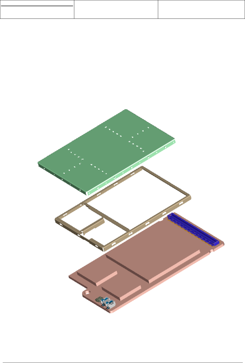
8. MECHANICAL SPECIFICATION WITH CONNECTOR ............................................................................................ 43
9. INTEGRATION.......................................................................................................................................................... 46
9.1 120 PINS CONNECTOR ......................................................................................................................... 46
9.1.1 MO130 connector ................................................................................................................... 46
9.1.2 Mother board connector.......................................................................................................... 47
9.2 MO130 ANTENNA CONNECTOR ........................................................................................................... 48
9.3 BATTERY CONNECTOR ........................................................................................................................ 49
ANNEXE 1 : REFERENCE SENSITIVITY LEVEL ............................................................................................................ 50
ANNEXE 2 : IO DESCRIPTION ........................................................................................................................................ 51

s
e
Centre de Saint Christophe - URD 37
TELEPHONIE MOBILE
MOBILE PHONES
Ref. : SCT TMO MASV2 SPEC 14 N
Date : 28/03/03
E All rights reserved. Reproduction and disclosure prohibited Page 5
MO130 module for mobile applications
This document contains information on a product under development. SAGEM reserves the right to change or discontinue this product
without notice.
1. OVERVIEW
1.1 OBJECT OF THE DOCUMENT
This document gives an overview of the MO130 module: a miniature, single-side board, tri-band GSM/GPRS
module, ready for integration in mobile application like vehicle-mounted or vending machines…
It describes the main functionalities (GPRS / GSM 900MHz / DCS 1800MHz / PCS 1900MHz, interface to a
melody chip, LCD interface, SIM interface, vibrator interface, audio interfaces for speaker/microphone or
accessories, battery interface, battery charging interface…) of this module as well as the electrical interfaces,
the mechanical specification (dimension, form…) and the electrical specification of the module.
1.2 REFERENCE DOCUMENTS
SCT U37 MT SPEC 117 C MASV2 module – Target specification
SCT TMO MASV2 SPEC 57 F MO130 module application note
1.3 STANDARDS COMPLIANCE
• GSM 02.60: "Digital cellular telecommunications system (Phase 2+); Stage 1 Service Description of the
General Packet Radio Service (GPRS)". Version 6.3.0.
• GSM 03.03: "Digital cellular telecommunications system (Phase 2+); Numbering, addressing and
identification". Version 6.6.0.
• GSM 03.13: "Digital cellular telecommunications system (Phase 2+); Discontinuous Reception (DRX) in
the GSM system". Version 6.0.0.
• GSM 03.60: "Digital cellular telecommunications system (Phase 2+); General Packet Radio Service
(GPRS); Service description; Stage 2". Version 6.7.0.
• GSM 03.64: "Digital cellular telecommunications system (Phase 2+); General Packet Radio Service
(GPRS);Overall description of GPRS radio Interface; Stage 2". Version 6.4.0.
• GSM 04.02: "Digital cellular telecommunications system (Phase 2+); GSM Public Land Mobile Network
(PLMN) access reference configuration". Version 6.0.0.
• GSM 04.03: "Digital cellular telecommunications system (Phase 2+); Mobile Station - Base Station
System (MS - BSS) interface Channel structures and access capabilities". Version 6.0.0.
• GSM 04.04: "Digital cellular telecommunications system (Phase 2+); Layer 1 General requirements".
Version 6.0.0.
• GSM 04.05: "Digital cellular telecommunications system (Phase 2+); Data Link (DL) layer General
aspects". Version 6.0.1.
• GSM 04.07: "Digital cellular telecommunications system (Phase 2+); Mobile radio interface signalling
layer 3 General aspects". Version 6.5.1.
• GSM 04.08: "Digital cellular telecommunications system (Phase 2+);Mobile radio interface layer 3
specification". Version 6.11.0.
• GSM 04.60: "Digital cellular telecommunications system (Phase 2+); General Packet Radio Service
(GPRS); Radio Link Control/Medium Access Control (RLC/MAC) protocol". Version 6.9.0.
• GSM 04.64: "Digital cellular telecommunications system (Phase 2+); General Packet Radio Service
(GPRS); Logical Link Control (LLC)". Version 6.7.0.
• GSM 04.65: : "Digital cellular telecommunications system (Phase 2+); General Packet Radio Service
(GPRS); Mobile Station (MS) - Serving GPRS Support Node (SGSN); Sub network Dependent
Convergence Protocol (SNDCP)". Version 6.7.0.

s
e
Centre de Saint Christophe - URD 37
TELEPHONIE MOBILE
MOBILE PHONES
Ref. : SCT TMO MASV2 SPEC 14 N
Date : 28/03/03
E All rights reserved. Reproduction and disclosure prohibited Page 6
MO130 module for mobile applications
This document contains information on a product under development. SAGEM reserves the right to change or discontinue this product
without notice.
• GSM 05.02: "Digital cellular telecommunications system (Phase 2+); Multiplexing and multiple access on
the radio path". Version 6.9.0.
• GSM 05.03: "Digital cellular telecommunications system (Phase 2+); Channel coding". Version 6.2.1.
• GSM 05.08: "Digital cellular telecommunications system (Phase 2+); Radio subsystem link control".
Version 6.8.0.
• GSM 05.10: "Digital cellular telecommunications system (Phase 2+); Radio subsystem synchronisation".
Version 6.6.0.
• GCF-CC (V.3.5.0) and GT.01.
• NAPRD.03 (V.2.5.1).
1.4 COMPLIANCE WITH FCC GUIDELINES
Fix-mount and mobile devices incorporating M0130 modules must be designed to maintain a minimum
separation distance of 20 cm between the antenna and the end user to satisfy RF exposure requirements for
mobile transmitting devices.
1.5 TERMS AND ABBREVIATION
ADC Analog to Digital Converter
ADPCM Adaptive Delta Pulse Code Modulation
AFC Application Frequency Correction
ASIC Application Specific Integrated Circuit
BMP Bitmap
CODEC Coder-Decoder
CTS Clear To Send
DAC Digital to Analog Converter
DAI Digital Analog Interface
DCS Digital
DSP Data Signal Processor
DSR Data Set Ready
DTR Data Terminal Ready
EGSM Enhanced GSM
EMS Enhanced Messaging Services
ESD Electrostatic Discharge
ETS European Telecommunication Standard
GSM Global Standard for Mobile communication
GPRS Global Packet Radio Services
IC Integrated Circuit
IEEE Institute of Electrical and Electronics Engineers
I/O Input / Output
IRDA Infra Red
ISO International Standards Organisation
ITU International Telecommunication Union
JPEG Joint Picture Expert Group
JTAG Joint Test Action Group
KBPS Kbit per second
LCD Liquid Crystal Display
LED Diode
LNA Low Noise Amplifier
MBPS Mbit per second
MIDI Musical Instrument Digital Interface
MMI Man Machine interface
PA Power Amplifier
PBCCH Packet Broadcast Channel
PCB Printed Circuit Board
PCS Personal Communication System
s
e
Centre de Saint Christophe - URD 37
TELEPHONIE MOBILE
MOBILE PHONES
Ref. : SCT TMO MASV2 SPEC 14 N
Date : 28/03/03
E All rights reserved. Reproduction and disclosure prohibited Page 7
MO130 module for mobile applications
This document contains information on a product under development. SAGEM reserves the right to change or discontinue this product
without notice.
PLL Phase Locked Loop
PNG Portable Network Graphics
RAM Random Access Memory
RF Radio Frequency
RI Ring Indication
RMS Root Mean Square
RTS Ready To Send
RX Receive direction
SIM Subscriber Identification Module
SMS Short Message Service
SRAM Static Random Access Memory
TBC To Be Confirmed
TBD To Be Defined
TX Transmit direction
UART Universal Asynchronous Receiver and Transmitter
USB Universal Serial Bus
USSD Unstructured Supplementary Service Data
VCO Voltage Controlled Oscillator
WAP Wireless Application Protocol
WBMP Wide Bitmap
1.6 PRODUCT FEATURES
Temperature range
Normal range: -10°C to +55°C (full compliant)
Extended range: -20°C to –10°C and +55°C to +70°C
(functional without any risk for the network)
Storage: -40°C to °85°C
Weight (in g) 10.5g
ESD ESD protected, < 1kv or 2kv (see application note)
Physical dimensions 34x54.4x3 mm (typical)
Connection 120 pins connector + 1 antenna connection + 1
battery connection
Decoupling capacitors Mainly integrated.
Power supply 3.45V to 5V range, 3.8V nominal.
Power consumption
Off mode: 120uA (typ)
Standby mode: 2.5mA (typ)
Communication mode: 280mA typ (average in GPRS
4+1 at max power)
Communication mode: 1800mA (peak during TX slot)
Power supply connector Dedicated connector.
Battery charge management and interface Battery charge management is included. The charger
interface is provided on 120 pins connector.
Antenna No antenna included in the module.
Antenna connector
50 ohms with coaxial connector.
The return loss of the external antenna has to be
better than –10dB (50Ohms reference) in all the
frequency range.
Frequency bands EGSM900 + DCS1800 + PCS1900
Voice codecs Half Rate, Full Rate, Enhanced Full Rate
GSM class Small MS
Transmit power Class 4 (2W) for EGSM900
Class 1 (1W) for DCS1800 / PCS1900
Supported SIM card 3V SIM cards.
To prevent SIM card’s damages, the power supply of

s
e
Centre de Saint Christophe - URD 37
TELEPHONIE MOBILE
MOBILE PHONES
Ref. : SCT TMO MASV2 SPEC 14 N
Date : 28/03/03
E All rights reserved. Reproduction and disclosure prohibited Page 8
MO130 module for mobile applications
This document contains information on a product under development. SAGEM reserves the right to change or discontinue this product
without notice.
the module has to be turned off before any
manipulation of the SIM card.
SIM slot
Not included on the module. Signals for the
management of the SIM card are provided on 120
pins connector.
Vibrator Not included in the module. Controls are provided on
120 pins connector.
Network LED Not included in the module. Controls are provided on
120 pins connector.
Keyboard / LCD backlight Not included in the module. Controls are provided on
120 pins connector.
Audio up-link 2 differential inputs are provided for microphone
(accessories and handset)
Audio down-link 2 differential inputs are provided for earphone
(accessories and handset)
Flap open/closed detection Dedicated interrupt input is provided on 120 pins
connector for the open/closed detection.
Keyboard interface 5x5 keyboard interface is provided on 120 pins
connector.
UART1 interface with flow control
Up to 115.2 Kbaud with autobauding.
Full flow control signals (+2.8V) are provided on 120
pins connector.
If a full compliant RS232 (+/-5V) serial interface is
needed:
The drivers (like MAX3232, ST3237CD, …) are not
included in the module and have to be added on the
main PCB.
A proven schematic to build the RS232 interface is
provided in application note.
IrDA interface or UART2 interface
Up to 115.2 Kbaud.
UART2 and IrDA are not multiplexed but could not be
used at the same time.
Data services GPRS, CSD, Fax
Supplementary services
Line identification, Call Waiting, Call Hold, Call
Forwarding, Multiparty, Closed User Group, Call
Barring, Advice of Charge, USSD
USB interface
Not integrated in the module.
It can be added by means of a dedicated micro-
controller with USB capabilities.
Melody chip interface
The melody chip is not integrated in the module but
the interface is provided (power supply, clock, audio,
serial link) on 120 pins connector.
Serial Interface A serial interface is provided on 120 pins connector in
order to manage an external LCD and a chip melody.
Parallel Interface
A parallel interface (16 bits) is provided on 120 pins
connector (7 addresses, 2 chip select and OE, RW
signals are available).
Reset pin Available (reset of all the system including backup)
Power on pin Available
General purpose I/Os pin See chapter
GPRS SMG 31bis, Multi slot class 8 (class 10 in future
versions), class B terminal, PBCCH support
WAP 1.2
GSM/DCS certification GCF-CC V.3.5.0 and GT.01
s
e
Centre de Saint Christophe - URD 37
TELEPHONIE MOBILE
MOBILE PHONES
Ref. : SCT TMO MASV2 SPEC 14 N
Date : 28/03/03
E All rights reserved. Reproduction and disclosure prohibited Page 9
MO130 module for mobile applications
This document contains information on a product under development. SAGEM reserves the right to change or discontinue this product
without notice.
PCS certification NAPRD.03 (V.2.5.1)
Multimedia objects download ringing tones, wallpapers, icons, games, screen
savers
Picture / animation formats supported WBMP, BMP, JPEG, PNG, GIF, SAGEM proprietary
formats
Audio formats supported MIDI, iMelody, PCM, ADPCM, SAGEM proprietary
formats
Software customisation Customisable MMI
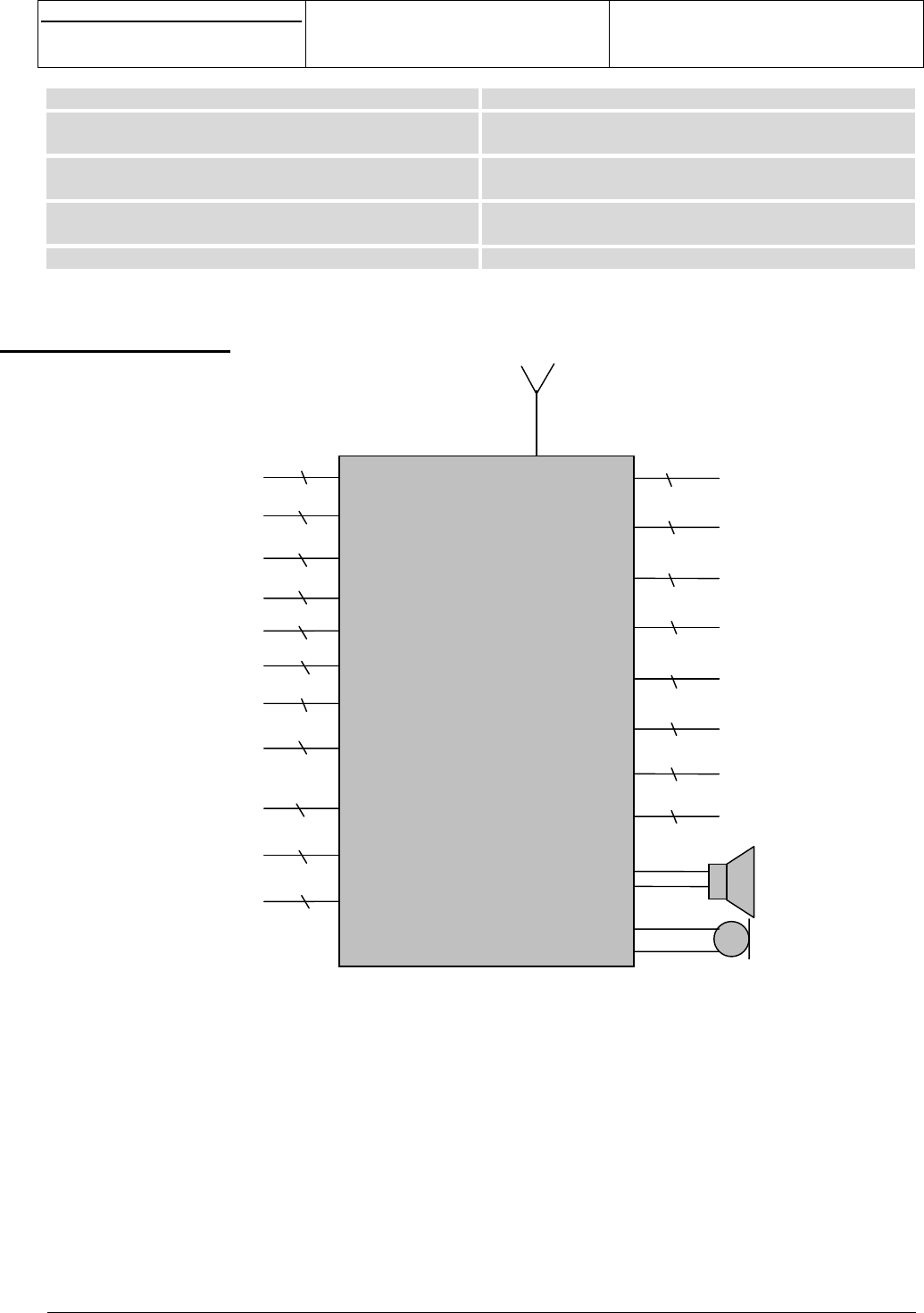
2. BLOC DIAGRAM
Figure 1
MO130 bloc diagram
See Pinout chapter for more details.
Earphone (accessory)
Microphone (accessory) Serial interface to LCD
MO130 module
GPRS / GSM900 / DCS1800
/
PCS1900
Keyboard
Battery charger
Battery (3.6V)
Vibrato
r
Melody chip interface
SIM interface (3V)
Serial link 2 or IRDA
interface
Serial link 1
with flow control
Antenna
Backlight
Network LED
Spare I/Os
2
3
1
2
2
5
5
3
8
11
2
2
8
2
Parallel interface (16 bits)
27
Backup
1
SPI interface
4
Flap detection
1
Interruption Inputs
2
s
e
Centre de Saint Christophe - URD 37
TELEPHONIE MOBILE
MOBILE PHONES
Ref. : SCT TMO MASV2 SPEC 14 M
Date : 04/03/03
E All rights reserved. Reproduction and disclosure prohibited Page 10
MO130 module for mobile applications
This document contains information on a product under development. SAGEM reserves the right to change or discontinue this product
without notice.
3. FUNCTIONAL DESCRIPTION
3.1 SIM
The SIM Card interface is compatible with the ISO 7816-3 IC card standard on the issues required by the
GSM 11.11 Phase 2+ standard. The module also supports Release 99 of the SIM Toolkit recommendation
too and supports a Fixed Dialling Number directory.
The SIM Card interface insures the detection (SIMCD), the power on (SIMVCC) of the SIM Card and the
communication with it through a data signal (SIMIO), a clock signal (SIMCLK) and a reset signal (SIMRST).
Signal Pin N° Description
SIMRST 5SIM reset, provided by Base-band processor
SIMCLK 4SIM clock, provided by Base-band processor
SIMIO 7SIM serial data line, input and output
SIMVCC 6SIM supply voltage
SIMCD 114 SIM insertion detection
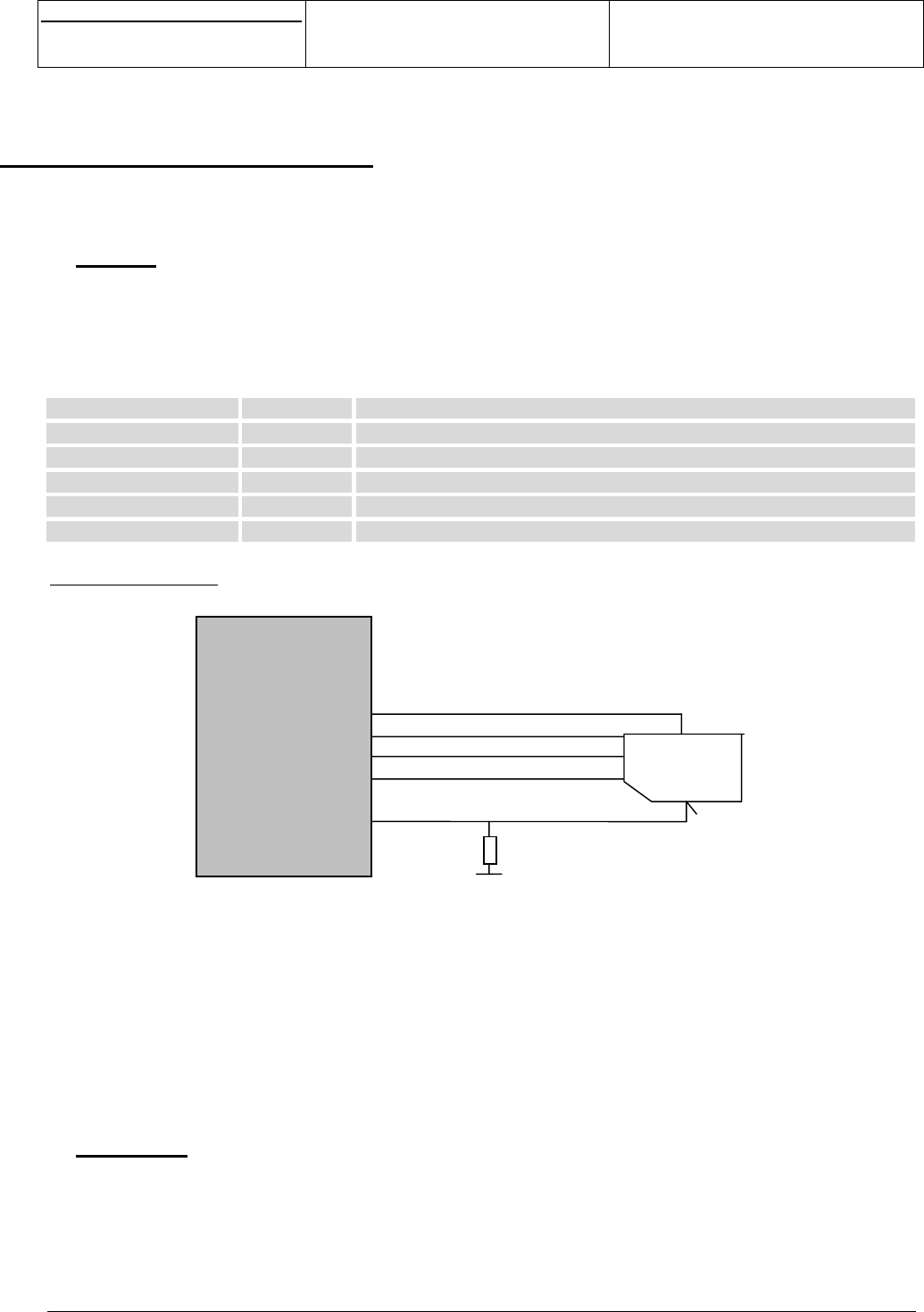
SIM card connection:
Figure 2
SIM connection
The SIMCD signal should be connected to the SIM card reader in order to get SIMCD at low level (GND)
when no card is present and at high level (SIMVCC) when card is present (external pull down needed when
SIM card connector with detection is used).
This interface includes main protections.
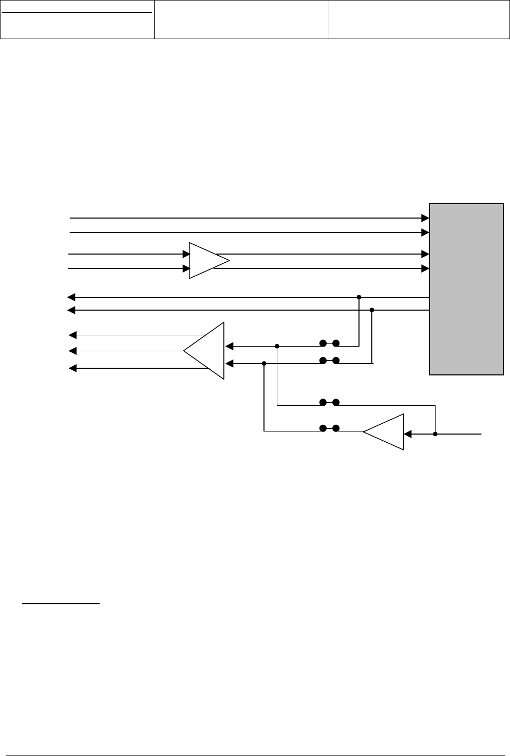
3.2 AUDIO
The module supports the following voice codecs:
• Half-Rate
• Full-Rate
• Enhanced Full Rate
It manages an external handset microphone (MICP/MICN) and an external handset earphone (HPP/HPN) in
differential mode.
MO130
SIMVCC
SIMIO
SIMRST
SIMCL
K
SIMCD
SIM card
In option
s
e
Centre de Saint Christophe - URD 37
TELEPHONIE MOBILE
MOBILE PHONES
Ref. : SCT TMO MASV2 SPEC 14 M
Date : 04/03/03
E All rights reserved. Reproduction and disclosure prohibited Page 11
MO130 module for mobile applications
This document contains information on a product under development. SAGEM reserves the right to change or discontinue this product
without notice.
The bias voltage of the microphone is provided directly on MICP/MICN pins.
There are three options for the earphone:
- One multi-mode earphone, as earpiece, hands free loudspeaker and melody/ring.
- Two earphones, one 32 Ohms as earpiece and one 8 Ohms as Ring/melody and as hands-free
loudspeaker if it is far from the microphone.
- one 32 Ohms earphone as earpiece.
The Module can also manage accessories (earphone and microphone) through dedicated lines
(BFRXP/BFRXN for earphone and BFTXP/BFTXN for microphone). The typical impedance for the earphone
is 150ohms.
Figure 3
Audio
This interface includes main protections.
To ensure proper operation of such sensitive signals, there have to be isolated from the other by ground on
mother board layout.
NB: To avoid destruction of module components, the HP inductance has to be 47nH +/- 5% @ 200MHz
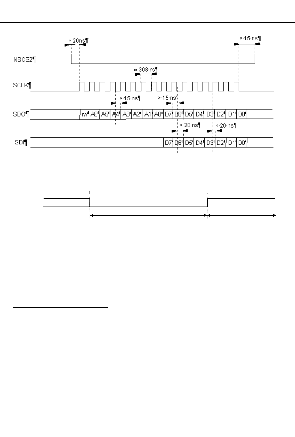
3.3 DISPLAY
A serial interface is provided on the module to manage an external LCD (256 colour) through data input
signal (DIMIW), data output signal (DOMIW), clock (CKMIW), reset (RESETLCD*), register select (RSLCD)
and two chip selects (CSMIW1 and CSMIW2), one dedicated to the LCD, the other to the chip melody.
Power supply of the LCD (ALIMLCD) is also provided through this interface.
This interface could be used to manage two LCDs. In this case, the module can’t manage a chip melody
through this serial link.
Base-band
Ampli+Filter
MICP
MICN
BFTXP
BFTXN
HPIN
BFRXP
BFRXN
HPP
HPN
LPHP
s
e
Centre de Saint Christophe - URD 37
TELEPHONIE MOBILE
MOBILE PHONES
Ref. : SCT TMO MASV2 SPEC 14 M
Date : 04/03/03
E All rights reserved. Reproduction and disclosure prohibited Page 12
MO130 module for mobile applications
This document contains information on a product under development. SAGEM reserves the right to change or discontinue this product
without notice.
Figure 4
Serial link timing
Figure 5
Reset serial link timing
This interface includes main protections.
If another LCD driver is used, the software would be provided by SAGEM, or at least the specific drivers will
be integrated by SAGEM. In that case a specific quotation is required.
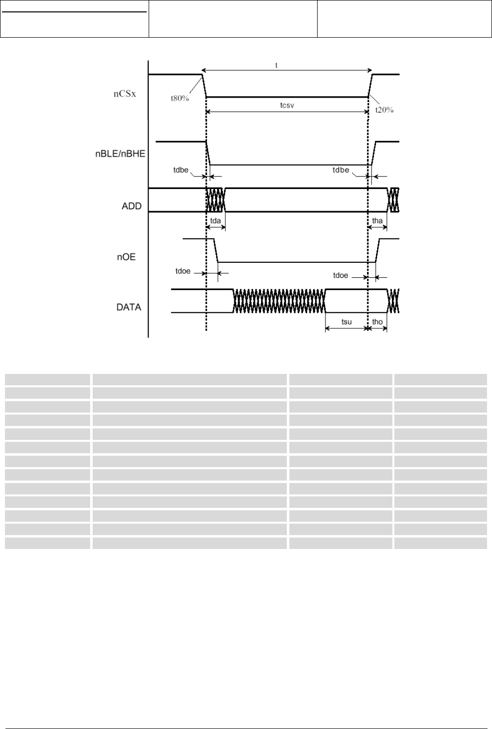
3.4 PARALLEL INTERFACE
A parallel interface is provided on the 120 pins connector. This interface include 16 bits data lines (D<0..15),
7 address lines (A<0>,A<1>, A<2>, A<3>, A<4>, A<5>,A<6>), Write control signal RW* (active low), Output
Enable signal OE* (active low) and two chip selects CS2 and CS3 (active low).
NB: The maximum capacitance acceptable on each signal of the parallel interface is 25pF (including copper
line capacitance, connectors capacitance…).
> 1µs
RESETLCD∗
Software initialisation
s
e
Centre de Saint Christophe - URD 37
TELEPHONIE MOBILE
MOBILE PHONES
Ref. : SCT TMO MASV2 SPEC 14 M
Date : 04/03/03
E All rights reserved. Reproduction and disclosure prohibited Page 13
MO130 module for mobile applications
This document contains information on a product under development. SAGEM reserves the right to change or discontinue this product
without notice.
Figure 6
Parallel link read timing
Timing Description Min (ns) Max (ns)
tcyc CPU frequency -1/Fcpu
tcsv Chip Select Valid tcyc (N+1)tcyc
tda NCS to Address valid -3.9
tha Address hold from nCS 0 -
tdbe NBHE, nBLE to nCS --0.2
tdoe NOE to nCS -4.5
tsu Input data setup to nCS 7.9 -
tho Input data hold from nCS 0 -
tsrw NCS to RnW Tcyc/2-tdrw -
tdrw RnW to nCS 1.3 2.2
tdso NCS to output data valid - Tsrw+14
thd Output data hold from RnW 1.1 -
N= Wait State number
Note: all timings computed for an external capacitance load of 10pF
s
e
Centre de Saint Christophe - URD 37
TELEPHONIE MOBILE
MOBILE PHONES
Ref. : SCT TMO MASV2 SPEC 14 M
Date : 04/03/03
E All rights reserved. Reproduction and disclosure prohibited Page 14
MO130 module for mobile applications
This document contains information on a product under development. SAGEM reserves the right to change or discontinue this product
without notice.
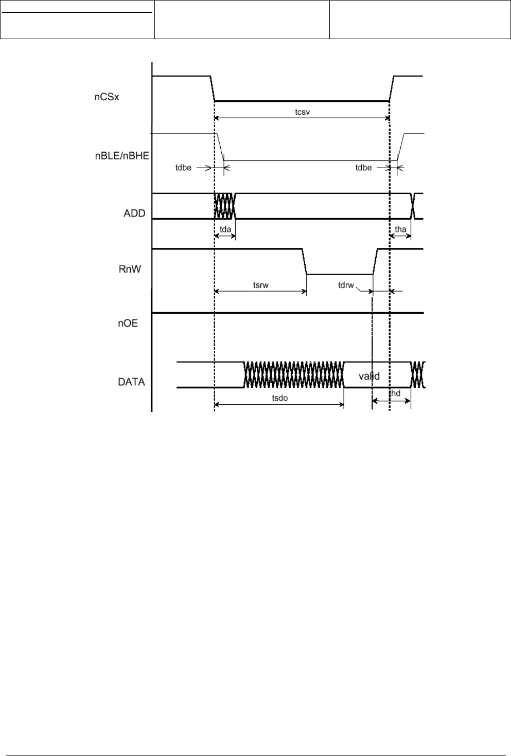
Figure 7
Parallel link write timing
NB: if needed, additional Wait State could be added by SAGEM.
Be careful: the maximum capacitance (components, lines, connectors,…) acceptable on each signal of the
parallel bus is 25pF.
s
e
Centre de Saint Christophe - URD 37
TELEPHONIE MOBILE
MOBILE PHONES
Ref. : SCT TMO MASV2 SPEC 14 M
Date : 04/03/03
E All rights reserved. Reproduction and disclosure prohibited Page 15
MO130 module for mobile applications
This document contains information on a product under development. SAGEM reserves the right to change or discontinue this product
without notice.
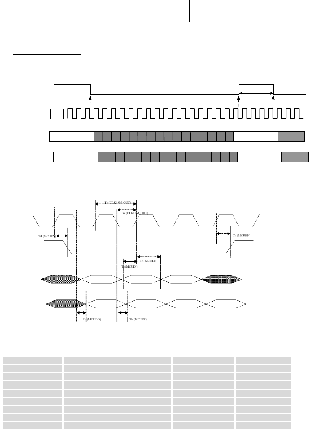
3.5 SPI INTERFACE
A SPI interface is provided on the 120 pins connector. This interface include Input/output data lines (DOSPI,
DISPI), clock (CLKSPI) and enable (ENSPI1).
Figure 8
SPI interface timing
Figure 9
SPI interface timing (second)
Timing Description Min (ns) Max (ns)
Tw(CLK13M_OUT) Pulse duration 30ns -
Tc(CLK13M_OUT) Cycle time 77ns -
Td(MCUDO) Delay time DOSPI -8.2ns
Th(MCUDO) Hold time DOSPI 0 -
Td(MCUEN) Delay time ENSPI1 -7.5ns
Th(MCUEN) Hold time ENSPI1 0 -
Ts(MCUDI) Setup DISPI 7.5ns -
Th(MCUDI) Hold time DISPI 2.5ns -
DISPI
116
CLKSPI
ENSPI1
lsb
msb
> 3 T13Mhz
msb
DOSPI lsb
msb msb
CLKSPI
ENSPI1
DISPI
DOSPI

s
e
Centre de Saint Christophe - URD 37
TELEPHONIE MOBILE
MOBILE PHONES
Ref. : SCT TMO MASV2 SPEC 14 M
Date : 04/03/03
E All rights reserved. Reproduction and disclosure prohibited Page 16
MO130 module for mobile applications
This document contains information on a product under development. SAGEM reserves the right to change or discontinue this product
without notice.
3.6 DATA
3.6.1 Data services
The module supports the following services:
• GPRS
• CSD: transparent and non-transparent up to 9600 BPS
• fax: class 1
Data sessions may be established over the main serial link or using the IrDA port (see below).
3.6.2 IrDA
This UART interface is compatible with 16C750 compliant devices. It includes the slow infra-red protocol in
order to be connected with an infra-red transmitter to any external data peripherals with an IrDA compliant
data interface.
This IrDA interface (TXIR, RXIR and CMDIRDA) provided by the module is compliant with the IrDA 1.0 SIR
up to 115.2 Kbaud.
This interface includes main protections.
3.6.3 UART 2
It is strongly recommended to let this interface externally accessible for Debug.
3.6.4 V24
A V24 interface is provided on external pins of the module with the following signals:
- RTS/CTS
- RX/TX
- DSR
- DTR
- DCD
- RI
It supports speeds up to 115.2 KBPS and may be used in autobauding mode.
This interface includes main protections.
3.7 MULTIMEDIA
The MO130 module offers various multimedia and downloading features:
• WAP 1.2 browser
• Download Fun services for customisation of screensavers, wallpapers, ringtones and call groups icons
• EMS V5
• Downloadable games using Infusio's ExEN platform (Optional through specific development)
The supported picture formats are:
• WBMP
• BMP
• JPEG

s
e
Centre de Saint Christophe - URD 37
TELEPHONIE MOBILE
MOBILE PHONES
Ref. : SCT TMO MASV2 SPEC 14 M
Date : 04/03/03
E All rights reserved. Reproduction and disclosure prohibited Page 17
MO130 module for mobile applications
This document contains information on a product under development. SAGEM reserves the right to change or discontinue this product
without notice.
• PNG
• GIF
• SAGEM proprietary B/W format
The supported screensavers formats are:
• Animated GIF
• SAGEM proprietary formats
The supported ringtones formats are:
• MIDI
• iMelody
• PCM (mono, 8kHz)
• SAGEM proprietary formats
3.8 MELODIES GENERATION
The module is hardware compatible with three solutions :
1. First solution
For MIDI files melodies the current available characteristics of the rendering is: 8 tones / 15 instruments /
4kHz bandwidth (available later 16 tones / 8 instruments / 4kHz bandwidth).
2. Second solution:
For rich rendering PCM (4 kHz bandwidth) is used, this format can also be used for over the air downloading.
3. Third solution: external chip melody
The characteristics of this solution are: 16 tones, 16 instruments, wide audio bandwidth.
In this case, some interfaces of the module could be used to manage a chip melody:
- 13MHz digital clock is available on external pins of the module for this application.
- HPIN audio digital signal is available on external pins of the module for this application.
- A serial link (DIMIW, DOMIW, CKMIW) could be used for the communication between the module and
the chip melody.
- VRIO +2.8V regulator output could be used to supply the chip melody.
Be careful, the serial link used for the melody chip is the same as the one used for the LCD (but 2 different
chip selects).
Most of this interface includes main protection.
The melody chip driver would be done by SAGEM if needed (specific development).
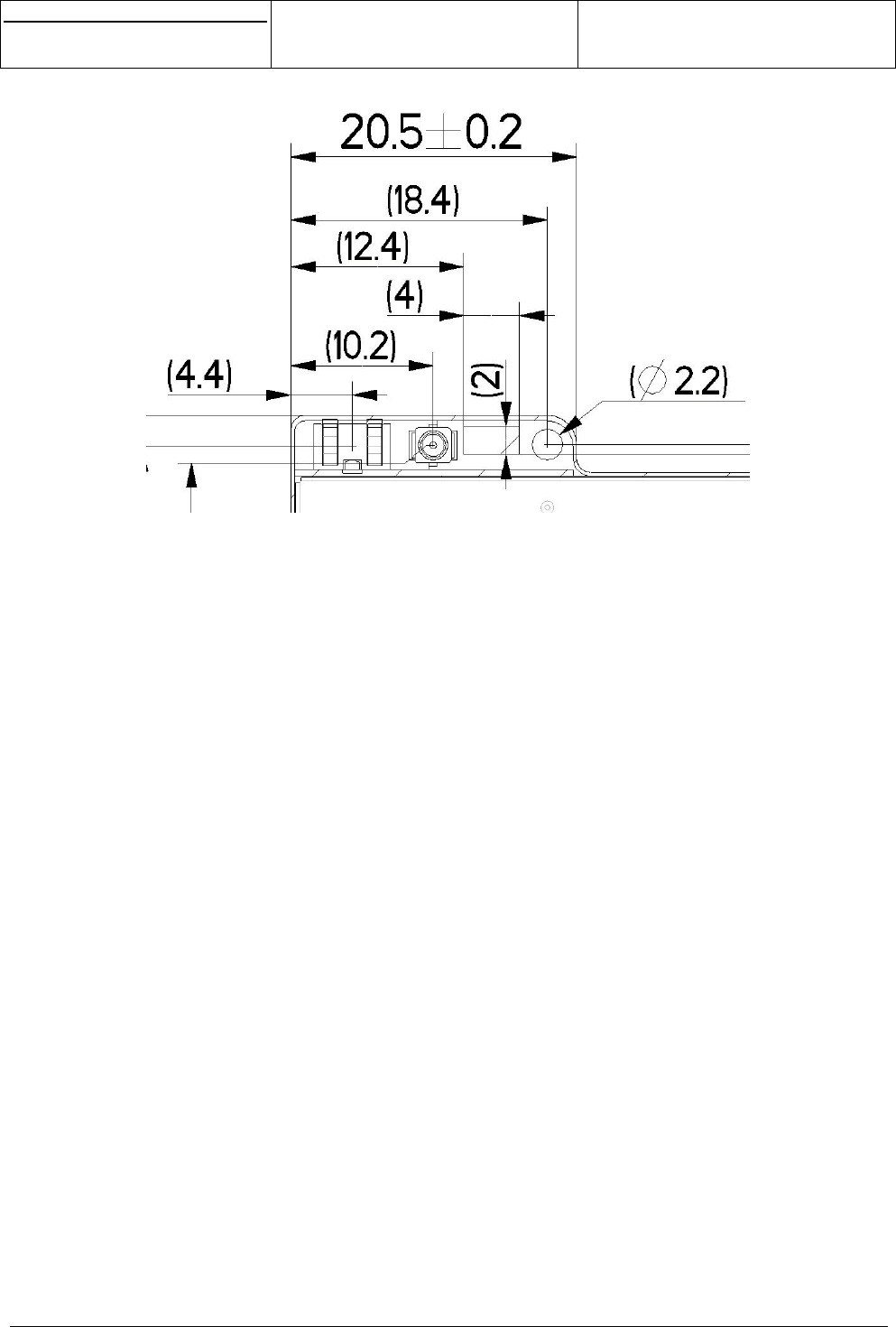
3.9 ANTENNA
Two accesses for the antenna connection are provided.
- one by mean of a 50ohms connector
- one by mean of a simple copper area
s
e
Centre de Saint Christophe - URD 37
TELEPHONIE MOBILE
MOBILE PHONES
Ref. : SCT TMO MASV2 SPEC 14 M
Date : 04/03/03
E All rights reserved. Reproduction and disclosure prohibited Page 18
MO130 module for mobile applications
This document contains information on a product under development. SAGEM reserves the right to change or discontinue this product
without notice.
Figure 10
Antenna area on the MO130
See into application note for more details.
NB:
- No ground in the neighbourhood of the pad for the antenna connection.
- 50ohms guaranteed only in conducted mode
- Functioning of the module in radiated mode depends on the respect of the radio rules.
s
e
Centre de Saint Christophe - URD 37
TELEPHONIE MOBILE
MOBILE PHONES
Ref. : SCT TMO MASV2 SPEC 14 M
Date : 04/03/03
E All rights reserved. Reproduction and disclosure prohibited Page 19
MO130 module for mobile applications
This document contains information on a product under development. SAGEM reserves the right to change or discontinue this product
without notice.
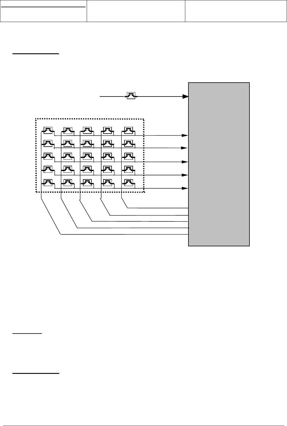
3.10 KEYPAD
A 5X5 keyboard could be managed by the module through the R1/R2/R3/R4/R5 row signals and
C1/C2/C3/C4/C5 column signals.
OUI signal performs the ON function. OFF signals performs OFF function.
Figure 11
Keyboard connection
(1) tbd (for example: refusal of an incoming call when the flap is closed)
(2) could be used for a particular function if required.
NC = these keys are connected internally in the MO130 module but are not managed.
The module uses the Tegic T9TM predictive input system.
3.11 DAI
A DAI interface is provided on the module for type approval tests.
3.12 CLOCKS
A 32KHz frequency clock and a 13MHz frequency digital clock are provided on external pins of the module.
The 13MHz clock could be used for the chip melody interface (see §3.6-Chip melody).
To ensure proper operation of such sensitive signals, there have to be isolated from the other by ground on
mother board layout.
R4
R3
R2
R1
C4
C3
C2
C1
C5
OUI
GND
MO130
R5
987
4
<
6OFF5OK
∧
>CLR* 0 #
∨123
VOL-VOL+♣(1) NC NC
NC
(2)

s
e
Centre de Saint Christophe - URD 37
TELEPHONIE MOBILE
MOBILE PHONES
Ref. : SCT TMO MASV2 SPEC 14 M
Date : 04/03/03
E All rights reserved. Reproduction and disclosure prohibited Page 20
MO130 module for mobile applications
This document contains information on a product under development. SAGEM reserves the right to change or discontinue this product
without notice.
3.13 POWER MANAGEMENT AND CHARGE
3.13.1 Battery
The power supply signal VBAT is 3.45V to 5V range and 3.8V nominal.
It has to be more than 3V, even during transients in order to avoid unwanted resets. The power supply
dropout has to be limited to 450mV, when the current consumption goes from minimum to maximum (0.1 to
1.8A). The noise level of the power supply has to be limited to 50mV RMS in the 100MHz – 1MHz frequency
range
A battery level measurement algorithm is turning the module OFF when average VBAT < 3.45V for more
than a few minutes.
For Li-ion battery, SAGEM advises to use Sanyo or LG battery. If other battery is used, SAGEM agreement
is needed (slight qualification tests).
This interface includes main protections.
3.13.2 VRDBB
+1.8V output is available on external pin of the module and could supply +1.8V external components (current
capability 10mA in active mode).
This interface includes main protections.
3.13.3 VRDBBDC
+1.8V input is available on external pin of the module. An external +1.8V DC-DC converter could eventually
be connected on this pin to supply the +1.8V to all the module. If no external DC-DC is added, this pin has to
be connected to the VRDBB output.
This interface includes main protections.
3.13.4 VRIO
+2.8V output is available on external pin of the module and could supply +2.8V external components (current
capability 10mA in active mode).
This interface includes main protections.
3.13.5 V56
+5.6V un-regulated power supply is available for Blue or White LEDs power supply on external pin of the
module with the following characteristics:
- 27mA capability in ON mode
- 5.5V to 5.7V in ON mode
This interface includes main protections.
3.13.6 Vbackup
External Backup could be supply through the VBACKUP input (from 2.2V to 3.2V).
If No external Backup is supplied, VBACKUP input has to be connected to VBAT signal.
s
e
Centre de Saint Christophe - URD 37
TELEPHONIE MOBILE
MOBILE PHONES
Ref. : SCT TMO MASV2 SPEC 14 M
Date : 04/03/03
E All rights reserved. Reproduction and disclosure prohibited Page 21
MO130 module for mobile applications
This document contains information on a product under development. SAGEM reserves the right to change or discontinue this product
without notice.
3.13.7 Charge
This interface manages the charge of the mobile, when a charger is connected, even in the following
conditions: deeply discharged battery, short-circuited battery and unconnected battery.
No additional components are needed.
Three types of charger can be managed by this interface:
Parameter Type 1 Type 2 Type 3
Unloaded max output
voltage (V)
711 16
Max voltage for max
current (V)
6.5 10.5 -
Current limitation (mA) 450 650 -
Voltage period (ms) - - 10
Equivalent output resistor
(ohms)
- - 8+/-10%
This interface includes main protections.
s
e
Centre de Saint Christophe - URD 37
TELEPHONIE MOBILE
MOBILE PHONES
Ref. : SCT TMO MASV2 SPEC 14 M
Date : 04/03/03
E All rights reserved. Reproduction and disclosure prohibited Page 22
MO130 module for mobile applications
This document contains information on a product under development. SAGEM reserves the right to change or discontinue this product
without notice.
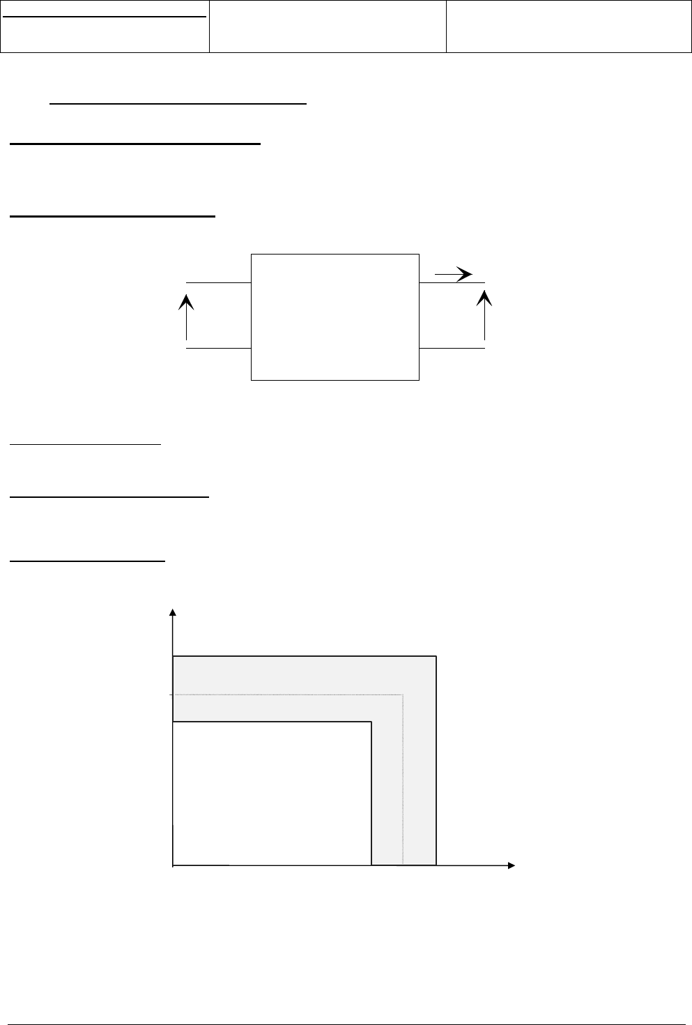
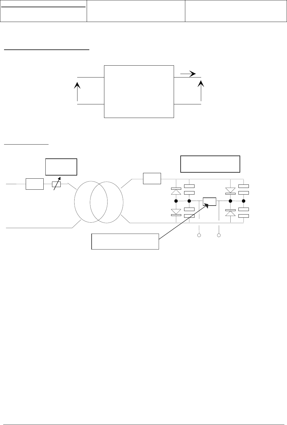
3.13.8 AC/DC switching charger
3.13.8.1 Operating temperature
0°C to +55°C.
3.13.8.2 Electrical ratings
Vs
Is
V
p
Batter
y
char
g
e
r
Class II equipment (EN 60950 § 1-2-4-2)
1 - Primary input voltage
98V < Vp < 254V ; F = 50/60Hz.
2 - Primary/secondary insulation
Security transformer class E (EN 60950 § 5-1)
Electric strength : reinforced insulation (EN 60950 § 5-3-2)
3 - Static output template
This template shows the Vs = f(Is) function.
550 mA
450 mA
Is
Vs
6V 7V
0
500 mA VALID AREA
s
e
Centre de Saint Christophe - URD 37
TELEPHONIE MOBILE
MOBILE PHONES
Ref. : SCT TMO MASV2 SPEC 14 M
Date : 04/03/03
E All rights reserved. Reproduction and disclosure prohibited Page 23
MO130 module for mobile applications
This document contains information on a product under development. SAGEM reserves the right to change or discontinue this product
without notice.
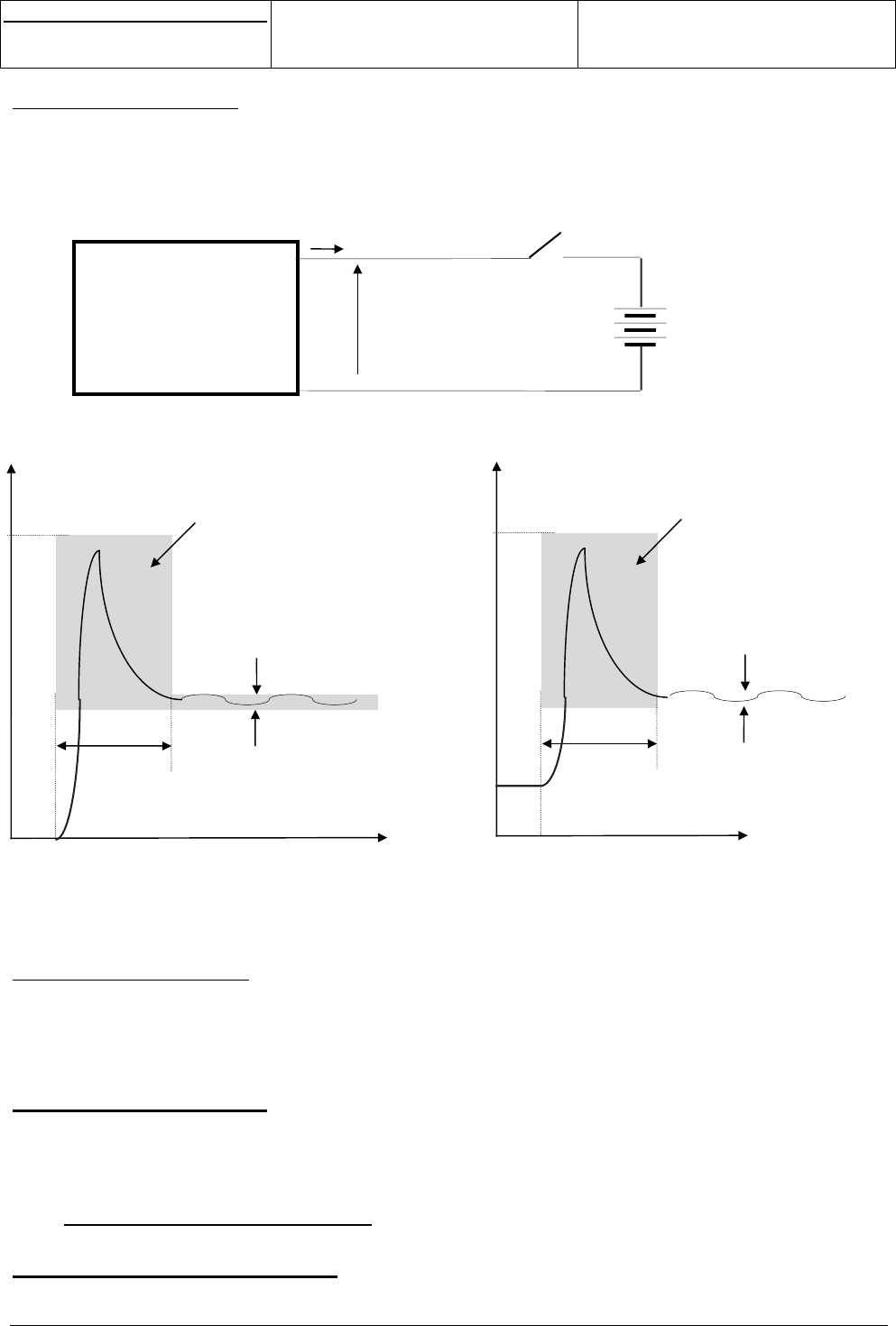
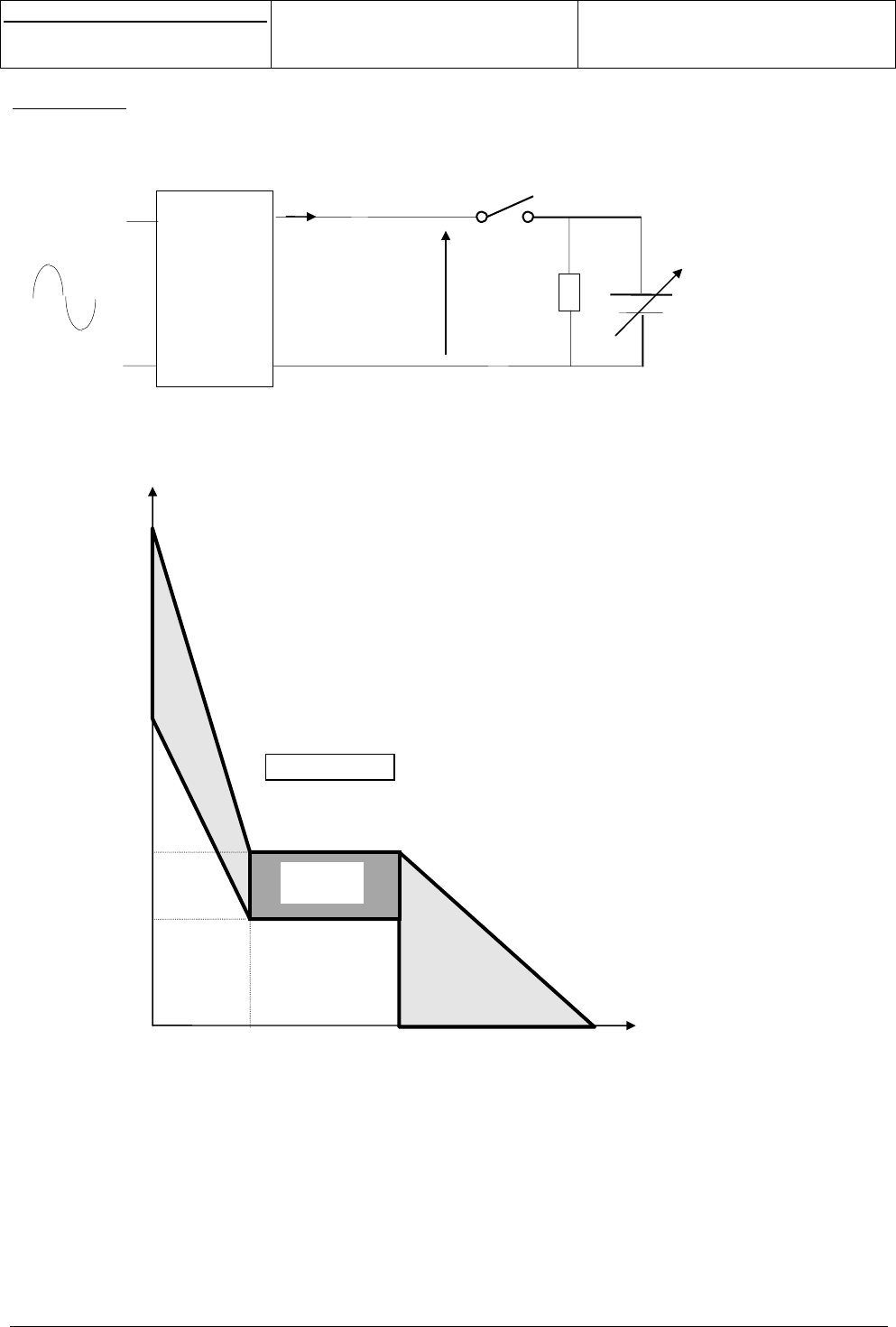
4 - Dynamic output template
An external device is controlling the battery charge by means of a switch S1, which can be switched on and
off.
Following templates shows the output current and voltage during transients, this feature is very important to
enable the charging control by controlling S1 (PWM).
5 - Reverse current (main off)
Main off or unplug, the current flowing from the battery to the charger have to stay smaller than « Ir » in order
to prevent discharge !
Ir < 100µA for VBAT ≤ 5V
3.13.8.3 Thermal ratings
The heating of the enclosure will comply with EN 60950 § 5-1
Tab. 16 - part 2.
3.13.9 Simple battery charger
3.13.9.1 Operating temperature
0°C to +55°C.
BATTERY CHARGER 0V <VBAT< 5V
Vs
I
s
S1
Is (dynamic)
Time
5A Max
5ms Max
S1 is
switched on
VALID AREA
Ripple : +/- 50m
A
Vs (dynamic)
Time
20V Ma
x
0.2ms Max
S1 is
switched off
VALID AREA
TBD
s
e
Centre de Saint Christophe - URD 37
TELEPHONIE MOBILE
MOBILE PHONES
Ref. : SCT TMO MASV2 SPEC 14 M
Date : 04/03/03
E All rights reserved. Reproduction and disclosure prohibited Page 24
MO130 module for mobile applications
This document contains information on a product under development. SAGEM reserves the right to change or discontinue this product
without notice.
3.13.9.2 Electrical ratings
Vs
Is
V
p
Batter
y
char
g
e
r
Class II equipment (EN 60950 § 1-2-4-2)
1 - Bloc definition
Equivalent resistance : Req = K2 Rp + Rs = 8,3Ω +/-10% ( for 20°C Ambient )
Transformation Ratio : K = 0,038
NOTA : Rs can be realise by coil resistor and if necessary by external resistor
NOTA2 : Without output capacitor to avoid current over load through GSM switch
R
p
Rs
K
Thermal
Protection
Four diodes 1N4003
Four capacitors 10nF
Over Voltage protection
( leakage self effect)
s
e
Centre de Saint Christophe - URD 37
TELEPHONIE MOBILE
MOBILE PHONES
Ref. : SCT TMO MASV2 SPEC 14 M
Date : 04/03/03
E All rights reserved. Reproduction and disclosure prohibited Page 25
MO130 module for mobile applications
This document contains information on a product under development. SAGEM reserves the right to change or discontinue this product
without notice.
2 - Test circuit
This design show the test circuit
5.2V
Is moyen
Vs ≅ VBAT + 0.6V
500mA
3.6V
150mA 1,2A
15V
NORMAL
C
HAR
G
E
VALID AREA
9V
CHARGER
Vp +/-10%
Is
Vs3
Ω
+
K1
s
e
Centre de Saint Christophe - URD 37
TELEPHONIE MOBILE
MOBILE PHONES
Ref. : SCT TMO MASV2 SPEC 14 M
Date : 04/03/03
E All rights reserved. Reproduction and disclosure prohibited Page 26
MO130 module for mobile applications
This document contains information on a product under development. SAGEM reserves the right to change or discontinue this product
without notice.
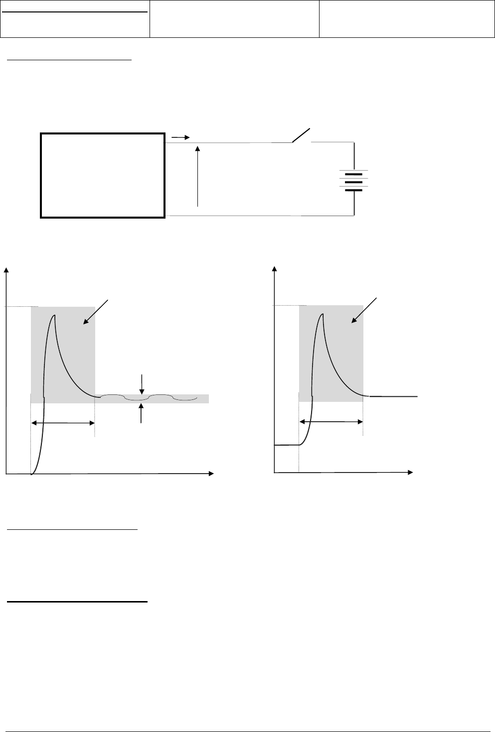
3 - Dynamic output template
An external device is controlling the battery charge by means of a switch S1, which can be switched on and
off.
Following templates shows the output current and voltage during transients, this feature is very important to
enable the charging control by controlling S1 (PWM).
4 - Reverse current (main off)
Main off or unplug, the current flowing from the battery to the charger have to stay smaller than « Ir » in order
to prevent discharge !
Ir < 100µA for VBAT ≤ 5V
3.13.9.3 Thermal ratings
The heating of the enclosure will comply with EN 60950 § 5-1
Tab. 16 - part 2.
Thermal tests will be done with 230V +10%, the duration of the tests will be at least 3 hours stabilisation ,
the test circuit will be conform to paragraph 4.4 with K1 closed .
Bobbin temperature elevation have to be lower than 75°C in all cases , to insure a final temperature lower
than 115°C for 40°C ambient temperature .
Primary resistance increase with temperature and ∆θ = ∆Rp / ( Rp . 4,2 10-3 )
Is (dynamic)
Time
Ri
pp
le : +/- 50m
A
5A Max
5ms Max
S1 is
switched on
VALID AREA
Vs (dynamic)
Time
20V Ma
x
0.2ms Max
S1 is
switched off
VALID AREA
BATTERY CHARGER 0V <VBAT< 5V
Vs
I
s
S1

s
e
Centre de Saint Christophe - URD 37
TELEPHONIE MOBILE
MOBILE PHONES
Ref. : SCT TMO MASV2 SPEC 14 M
Date : 04/03/03
E All rights reserved. Reproduction and disclosure prohibited Page 27
MO130 module for mobile applications
This document contains information on a product under development. SAGEM reserves the right to change or discontinue this product
without notice.
Verify : ∆Rp / Rp (20°C) < 0.315
Report have to be made by the supplier stipulating the bobbin and the enclosure temperature elevation .
3.14 ACCESSORIES
Accessories connection has to be defined more precisely.
With the MO130 module, the following accessories could be connected :
- a pedestrian stereo or non stereo hand-free kit
- a battery charger
- an automotive hand-free kit
These interfaces includes main protections.
3.15 MANUFACTURER MMI CUSTOMIZATION
The MO130 module already includes built-in MMI. This MMI can be customised by customer with SAGEM
help.
Options for customisation include :
• custom bitmaps and animations (with pre-determined sizes): start animation, menus animations,
icons…
• custom fonts (with pre-determined sizes)
• custom messages (provided they fit in the MMI design)
• custom screen-savers
• enabling or disabling some features
If more customisation is required, this has to be discussed with SAGEM.
As explained in other chapters, if a specific LCD or keyboard configuration is needed, SAGEM will take the
responsibility to develop the required software drivers. In case of already available drivers, SAGEM will take
the responsibility to integrate them in the software.
All these options are submitted to specific software development on SAGEM side. Therefore, MMI options
require separate, dedicated quotation.
3.16 OTHER FUNCTIONS
3.16.1 Flap
An interrupt pin is available on external pin of the module for the Open/closed detection of a clam mobile.
3.16.2 Buzzer
This interface is not provided at this time but could be included if requested.
3.16.3 Backlight
3.16.3.1 Red or Green LEDs
A current generator (BACKKEY) is dedicated to backlight of the LCD or the keyboard with the following
characteristics:
- Output voltage Von from 1.7V to 3.7V, 2.5V typ.
s
e
Centre de Saint Christophe - URD 37
TELEPHONIE MOBILE
MOBILE PHONES
Ref. : SCT TMO MASV2 SPEC 14 M
Date : 04/03/03
E All rights reserved. Reproduction and disclosure prohibited Page 28
MO130 module for mobile applications
This document contains information on a product under development. SAGEM reserves the right to change or discontinue this product
without notice.
- Output current Ion from up to 150mA typ.
- Output voltage Voff from 3.0V to 5.5V, 3.8V typ.
- Output current Ioff 200nA max.
- Analog output, programmable current NMOS type.
An other current generator (BACKLCD) is dedicated to backlight of the LCD or the keyboard with the
following characteristics:
- Output voltage Von from 1.7V to 3.7V, 2.5V typ.
- Output current Ion up to 80mA typ.
- Output voltage Voff from 3.0V to 5.5V, 3.8V typ.
- Output current Ioff 100nA max
- Analog, programmable NMOS type, or Digital output
Figure 12
LED (baklight) connection
This interface includes main protections.
3.16.3.2 Blue and White LEDs
V56 power supply could be used to supply maximum 3 blue or white LEDs (IV56 = 27mA max). To connect
more blue or White LEDs; an external driver has to be added.
3.16.3.3 Multicolour LEDs and EL film
An external driver has to be added to manage the multicolour LEDs or White LEDs.
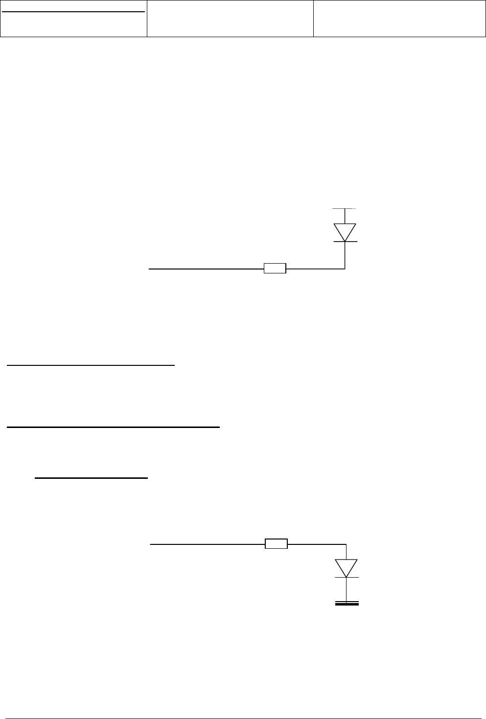
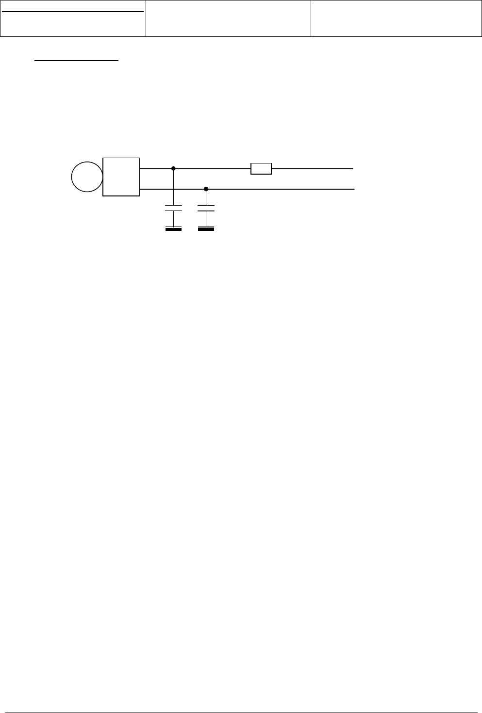
3.16.4 Network LED
Two external pin of the module (LEDR and LEDG) are dedicated to network LED.
Figure 13
Network LED connection
This interface includes main protections.
BACKLCD
or
BACKKEY
VBAT
LEDR or
LEDG
s
e
Centre de Saint Christophe - URD 37
TELEPHONIE MOBILE
MOBILE PHONES
Ref. : SCT TMO MASV2 SPEC 14 M
Date : 04/03/03
E All rights reserved. Reproduction and disclosure prohibited Page 29
MO130 module for mobile applications
This document contains information on a product under development. SAGEM reserves the right to change or discontinue this product
without notice.
3.16.5 Vibrator
An external pin of the module provides vibrator command (CMDVIB) to drive a vibrator with the following
characteristics:
- Rs series resistance from 10 ohms to 50 ohms.
- Zl series inductance from 50uH to 100uH.
- Cl load capacitance from 0 to 1nF.
- Ioff quiescent current 100nA max.
Figure 14
Vibrator connection
This interface includes main protections.
+
VIB
-
VBAT
CMDVIB
s
e
Centre de Saint Christophe - URD 37
TELEPHONIE MOBILE
MOBILE PHONES
Ref. : SCT TMO MASV2 SPEC 14 M
Date : 04/03/03
E All rights reserved. Reproduction and disclosure prohibited Page 30
MO130 module for mobile applications
This document contains information on a product under development. SAGEM reserves the right to change or discontinue this product
without notice.
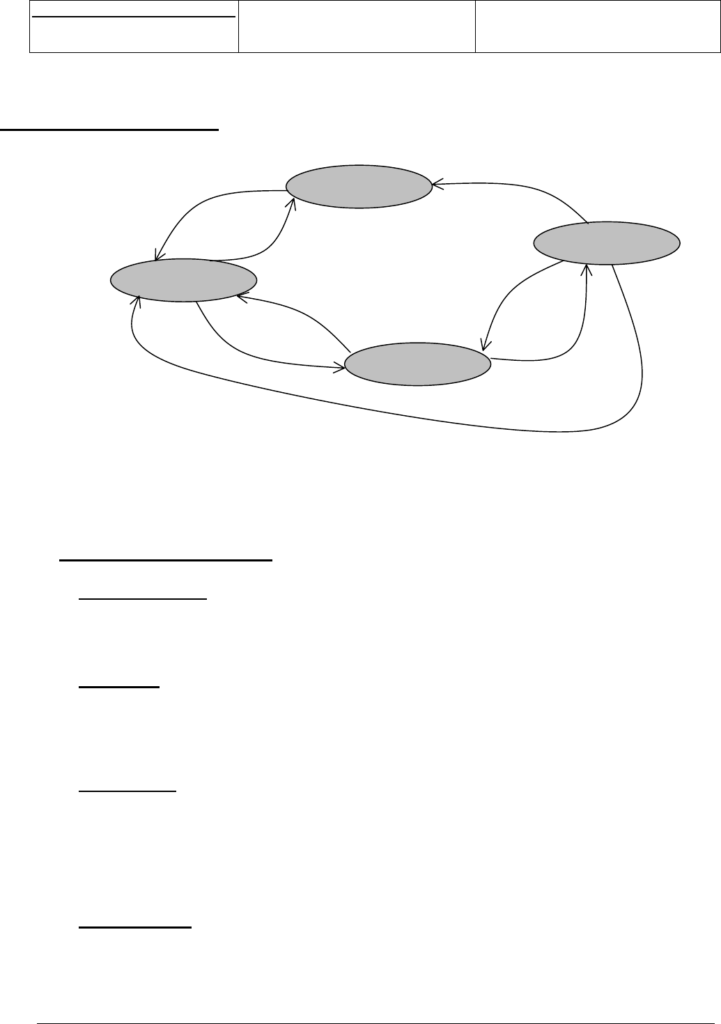
4. OPERATING MODES
Figure 15
Operating modes state diagram
4.1 MODES DESCRIPTION
4.1.1 No supply
VBAT < 3.2V and VBACKUP < 2.2V.
All functions and power supplies are OFF: VRDBB, VRIO, V56 = 0.
4.1.2 OFF
VBAT > 3.2V or external Backup VBACKUP > 2.2V.
The RTC only is running (32kHz). For internal reasons, V56 is in low power configuration (V56 = 4.5V and
Iv56 = 1mA max). All other functions and power supplies are OFF: VRDBB, VRIO = 0.
4.1.3 Active
The module is active: all the functions are running and all the power supplies are ON and in full power mode
(full consumption).
VRDBB = +1.8V
VRIO = +2.8V
V56 = +5.6V
4.1.4 Standby
The module is in standby mode: the power supplies are ON and in low power mode.
This mode is typically use when the module is connected to the network and checking periodically if there is
an incoming call.
Wake-up
Sleep (automatic)
Switch_off
Switch_on
Switch_off
Power_on
Power_off
Power_off
No supply
OFF
Active
Standby

s
e
Centre de Saint Christophe - URD 37
TELEPHONIE MOBILE
MOBILE PHONES
Ref. : SCT TMO MASV2 SPEC 14 M
Date : 04/03/03
E All rights reserved. Reproduction and disclosure prohibited Page 31
MO130 module for mobile applications
This document contains information on a product under development. SAGEM reserves the right to change or discontinue this product
without notice.
4.2 TRANSITIONS DESCRIPTION
4.2.1 Power_on
A battery is connected to the module with VBAT > 3.2V (and/or VBACKUP is switched ON).
4.2.2 Power_off
The battery is removed from the module (and/or VBACKUP is switched OFF).
4.2.3 Switch_on
The battery is already connected. The module starts when ON key is pressed or a charger is connected or
when wake up occurs.
4.2.4 Switch_off
The battery is connected. The software is turning off of the module when OFF key is pressed and VBAT >
3.2V.
4.2.5 Wake up
The actions to go from standby mode to active mode are:
- Charger connection
- Key pressed
- Incoming call
- Data cable connection
- V24 activity
s
e
Centre de Saint Christophe - URD 37
TELEPHONIE MOBILE
MOBILE PHONES
Ref. : SCT TMO MASV2 SPEC 14 M
Date : 04/03/03
E All rights reserved. Reproduction and disclosure prohibited Page 32
MO130 module for mobile applications
This document contains information on a product under development. SAGEM reserves the right to change or discontinue this product
without notice.
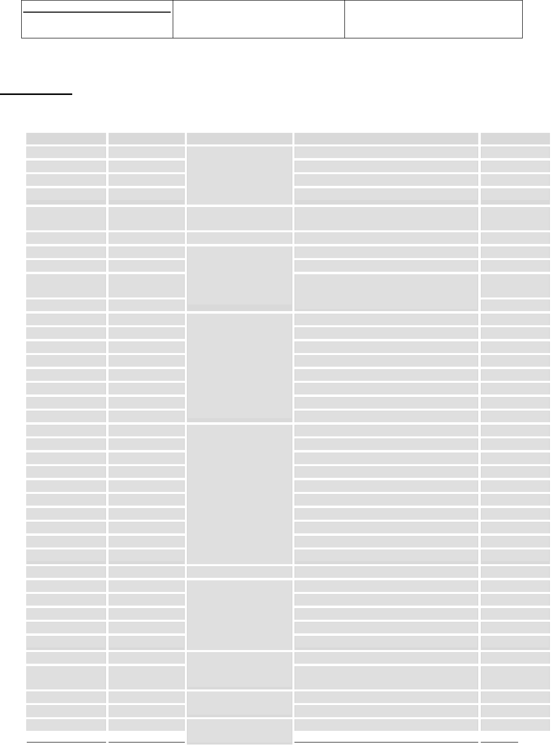
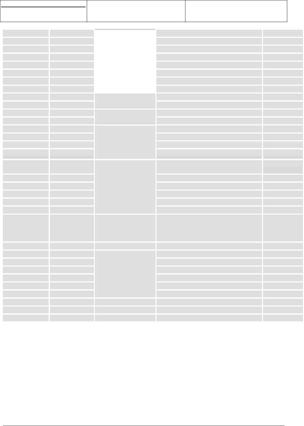
5. PINOUT
The following list of signals could change.
Signal name IO type Function Description Pin N°
DAIRST Input DAI reset 116
DAIOUT Output DAI output data 115
DAIIN Input DAI input data 117
DAICLK Input
DAI interface
DAI clock 118
SWANTANT Output Antenna switch
command
112
ITFLAP Input Flap interrupt Flap detection interruption 80
BACKLCD Output Backlight LED control 72
BACKKEY Output Backlight LED control 71
LEDR_BUZ Output 91
LEDG Output
LED control
Alarm LED control / buzzer control on
demand
Network LED control 90
RSLCD Output LCD driver register select 89
RESETLCD* Output LCD driver reset 88
ALIMLCD Output LCD driver power supply 75
DIMIW Input LCD driver input data of the serial link 86
DOMIW Output LCD driver output data of the serial link 84
CKMIW Output LCD driver clock of the serial link 85
CSMIW1 Output LCD1 driver chip select of the serial link 98
CSMIW2 Output
Serial interface to
connect LCD or chip
melody (2 chip
selects)
LCD2 driver chip select of the serial link 97
R1 Input Keyboard row 1 22
R2 Input Keyboard row 2 21
R3 Input Keyboard row 3 20
R4 Input Keyboard row 4 19
R5 Input Keyboard row 5 18
C5 Output Keyboard column 5 23
C4 Output Keyboard column 4 24
C3 Output Keyboard column 3 25
C2 Output Keyboard column 2 26
C1 Output
Keyboard interface
Keyboard column 1 27
OUI* Input ON key Keyboard ON key 113
SIMVCC Output SIM power supply 6
SIMRST Output SIM reset 5
SIMCLK Output SIM clock 4
SIMIO In/output SIM data 7
SIMCD Input
SIM interface
SIM insertion detection 114
BFTXP Input Differential input from microphone 52
BFTXN Input
To external
microphone
(accessory) Differential input from microphone 53
BFRXP Output Differential output to earphone 49
BFRXN Output
To external HP
(accessory) Differential output to earphone 50
MICP Input Microphone interface Differential input to handset microphone 63

s
e
Centre de Saint Christophe - URD 37
TELEPHONIE MOBILE
MOBILE PHONES
Ref. : SCT TMO MASV2 SPEC 14 M
Date : 04/03/03
E All rights reserved. Reproduction and disclosure prohibited Page 33
MO130 module for mobile applications
This document contains information on a product under development. SAGEM reserves the right to change or discontinue this product
without notice.
MICN Input Differential input to handset microphone 62
HPP Output Differential output to 32ohms or 8ohms
earphone
56
HPN Output Differential output to 8ohms earphone 57
LPHP Output
Earphone interface
Differential output to 32ohms earphone 55
HPIN Input Melody chip interface HP in for melody chip interface 59
CMDVIB Output Vibrator interface Vibrator command 79
RI Output Ring Indicator 109
DSR Output Data Send Ready 94
DCD Output Data Carrier Detect 110
DTR Input Data Terminal Ready 95
CTS Output Clear To Send 82
RTS Input Request To Send 83
TXD1 Output UART transmit 1 101
RXD1 Input
V24 interface with
flow control
UART receive 1 105
TXD2 Output UART transmit 2 103
RXD2 Input
UART interface
UART receive 2 104
TXIR Output IRDA transmit 100
RXIR Input IRDA receive 99
CMDIRDA Output
IRDA interface
IRDA command 96
INT Input 92
SCL Output 14
SDA In/out
Internal use
93
CHARGEUR Input Load interface Charge 69,70
ON* Output Accessories control 73
TESTRESETZ Input Reset Reset system signal 81
ITDATA Input Accessories detection Interrupt signal 76
CMDSW1 In/output I/O 107
CMDSW2 In/output
Spare IO
I/O 106
CINT Input Interrupt Interruption 111
D<0> In/output Data bus 33
D<1> In/output Data bus 34
D<2> In/output Data bus 35
D<3> In/output Data bus 36
D<4> In/output Data bus 37
D<5> In/output Data bus 38
D<6> In/output Data bus 39
D<7> In/output Data bus 40
D<8> In/output Data bus 41
D<9> In/output Data bus 42
D<10> In/output Data bus 43
D<11> In/output Data bus 44
D<12> In/output Data bus 45
D<13> In/output Data bus 46
D<14> In/output Data bus 47
D<15> In/output Data bus 87
A<0> In/output Address bus 32
A<1> In/output Address bus 78
A<2> In/output
Parallel interface
Address bus 77
s
e
Centre de Saint Christophe - URD 37
TELEPHONIE MOBILE
MOBILE PHONES
Ref. : SCT TMO MASV2 SPEC 14 M
Date : 04/03/03
E All rights reserved. Reproduction and disclosure prohibited Page 34
MO130 module for mobile applications
This document contains information on a product under development. SAGEM reserves the right to change or discontinue this product
without notice.
A<3> In/output Address bus 68
A<4> In/output Address bus 67
A<5> In/output Address bus 66
A<6> In/output Address bus 65
OE* Output Output Enable 30
RW* Output Read / Write 29
CS2 Output Chip select 2 31
CS3 Output Chip select 3 28
CLK13M Output 13MHz clock digital output 16
CLK32K Output
Clocks
32KHz clock digital output 9
ADC1 Input Battery type detection 11
DAC Output
ADC/DAC
Digital to analog converter 13
DISPI Input Data input 120
DOSPI Output Data output 102
CLKSPI Output Clock SPI 108
ENSPI1 Output
SPI bus
SPI enable 119
VBAT Input +3.6V battery power supply Bat. Conn. 1
V56 Output +5.6V output power supply 74
VRDBB Output +1.8V output power supply 3
VRDBBDC Input +1.8V DCDC output 1
VRIO Output +2.8V output power supply 2
VBACKUP Input
Power supply
Backup input 12
GND Ground Ground 8,10,15,17,48
,51,54,58,60,
61,64
Bat. Conn 2
OUT_ANT Output Antenna output Ant. conn.
TCLK Input JTAG Test point
TMS Input JTAG Test point
TDI Input JTAG Test point
TDODIGIT Output JTAG Test point
TDIANALOG Input JTAG Test point
TDOANALOG Output
JTAG interface
JTAG Test point
NBSCAN Input Boundary scan JTAG Test point
NEMU0 Output For debug Test point
NEMU1 Output For debug Test point
s
e
Centre de Saint Christophe - URD 37
TELEPHONIE MOBILE
MOBILE PHONES
Ref. : SCT TMO MASV2 SPEC 14 M
Date : 04/03/03
E All rights reserved. Reproduction and disclosure prohibited Page 35
MO130 module for mobile applications
This document contains information on a product under development. SAGEM reserves the right to change or discontinue this product
without notice.
6. ELECTRICAL SPECIFICATION
VOH High level output voltage
VOL Low level output voltage
VIH High level input voltage
VIL Low level input voltage
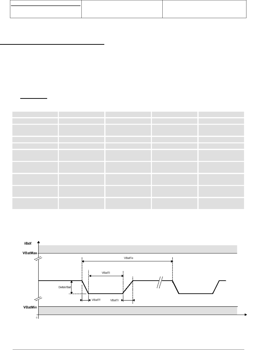
6.1 VBAT
The module is supplied through the VBAT signal with the following characteristics:
Parameter Name Min Typ Max
VBAT period (ms) VbatTe (*) 4.614 4.615 DC
VBAT low duration
(us)
VbatTi (*) 550 -VBAT period
VBAT rise time (us) VbatTr (*) 0 - -
VBAT fall time (us) VbatTf (*) 0 - -
VBAT maximum
voltage (V)
VbatMax (*) - - 5
VBAT minimum
voltage (V)
VbatMin (*) 3.45 - -
VBAT drop voltage
(mV)
DeltaVbat (*) - - 450 (**)
Transient voltage
(V)
3 - -
Noise level (Vrms)
@100MHz-1MHz
- - 50mV
(*): cf figure 16.
(**): for a new battery. Of course for old battery, this value will be higher and will create a reset (without MMI
message) of the mobile phone when the battery begins to be discharge.
Figure 16
VBAT voltage waveform
s
e
Centre de Saint Christophe - URD 37
TELEPHONIE MOBILE
MOBILE PHONES
Ref. : SCT TMO MASV2 SPEC 14 M
Date : 04/03/03
E All rights reserved. Reproduction and disclosure prohibited Page 36
MO130 module for mobile applications
This document contains information on a product under development. SAGEM reserves the right to change or discontinue this product
without notice.
NB: a battery level measurement algorithm is turning the module OFF when VBAT < 3.45V for more than a
few minutes.
6.2 POWER SUPPLIES
6.2.1 VRDBB (120 pin connector, pin 3)
Signal Min Typ Max Remarks
Voltage level 1.65V 1.80V 1.95V
Current capability
Active mode
- - 10mA
Current capability
Sleep mode
- - 1mA
Quiescent current
Active mode
-150µA-
Quiescent current
Sleep mode
-20µA-
Quiescent current
Disable
-1µA-
Rise time -10µs-
Protection
6.2.2 VRIO (120 pin connector, pin 2)
Signal Min Typ Max Remarks
Voltage level 2.70V 2.80V 2.90V
Current capability
Active mode
- - 10mA
Current capability
Sleep mode
- - 1mA
Quiescent current
Active mode
-150µA-
Quiescent current
Sleep mode
-20µA-
Quiescent current
Disable
-1µA-
Rise time -10µs-
Protection
6.2.3 V56 (120 pin connector, pin 74)
Signal Min Max Remarks
Voltage level 5.5V 5.7V
Current capability -27mA
Rise time - 2ms
Protection
Un-regulated
NB: in OFF mode, this power supply is in low power configuration (V56 = 4.5V and IV56 = 1mA max).

s
e
Centre de Saint Christophe - URD 37
TELEPHONIE MOBILE
MOBILE PHONES
Ref. : SCT TMO MASV2 SPEC 14 M
Date : 04/03/03
E All rights reserved. Reproduction and disclosure prohibited Page 37
MO130 module for mobile applications
This document contains information on a product under development. SAGEM reserves the right to change or discontinue this product
without notice.
6.2.4 ALIMLCD (120 pin connector, pin 75)
Signal Min Max Remarks
Voltage level 2.75V 2.85V
Current capability -10mA
Protection
s
e
Centre de Saint Christophe - URD 37
TELEPHONIE MOBILE
MOBILE PHONES
Ref. : SCT TMO MASV2 SPEC 14 M
Date : 04/03/03
E All rights reserved. Reproduction and disclosure prohibited Page 38
MO130 module for mobile applications
This document contains information on a product under development. SAGEM reserves the right to change or discontinue this product
without notice.
6.3 DAI INTERFACE
DAIRST, DAIIN, DAICLK and DAIOUT have the following characteristics:
VL (V) VH (V)Signal
Min Max Min Max
Remarks
DAIRST (in) -0.5 +0.8 +2.0 +3.2 Protection
DAICLK (in) -0.5 +0.8 +2.0 +3.2 Pull down
Protection
DAIIN (in) -0.5 +0.8 +2.0 +3.2 Pull down
Protection
DAIOUT (out) -+0.6 +2.4 -Protection
6.4 NETWORK LED
LEDR and LEDG have the following characteristics:
VL (V) VH (V)Signal
Min Max Min Max
Remarks
LEDR, LEDG (out) -+0.6 +2.4 -Protection
Iout max = 4mA
6.5 BACKLIGHT
BACKLCD and BACKKEY have the following characteristics:
Parameter Signal Min Typ Max Remarks
Von BACKLCD,
BACKKEY
1.7V 2.5V 3.7V
BACKKEY 120mA 150mA 180mAIon
BACKLCD 50mA 80mA 90mA
Voff BACKLCD,
BACKKEY
3.0V 3.8V 5.5V
BACKKEY 200nAIoff
BACKLCD 100nA
Protections
BACKLCD:
analog or digital
BACKKEY:
analog
6.6 SERIAL INTERFACE FOR LCD
RESETLCD*, RSLCD, DIMIW, DOMIW, CKMIW, CSMIW1, CSMIW2 have the following characteristics:
VL (V) VH (V)Signal
Min Max Min Max
Remarks
DIMIW (in) -0.5 +0.8 +2.0 +3.2 Protection
RESETLCD* (out) -+0.6 +2.4 -Pull down
Protection
Output (out) -+0.6 +2.4 -Protection
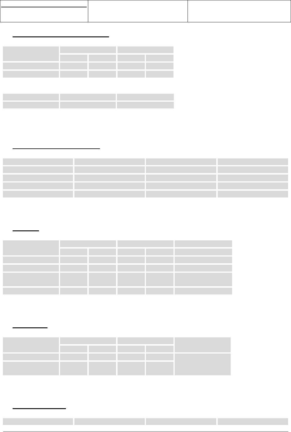
s
e
Centre de Saint Christophe - URD 37
TELEPHONIE MOBILE
MOBILE PHONES
Ref. : SCT TMO MASV2 SPEC 14 M
Date : 04/03/03
E All rights reserved. Reproduction and disclosure prohibited Page 39
MO130 module for mobile applications
This document contains information on a product under development. SAGEM reserves the right to change or discontinue this product
without notice.
6.7 KEYBOARD INTERFACE
R1, R2, R3, R4, R5, C1, C2, C3, C4 and C5 have the following characteristics:
VL (V) VH (V)Signal
Min Max Min Max
Input (R1/2/3/4/5) -0.5 +0.8 +2.0 +3.2
Output (C1/2/3/4/5) -+0.6 +2.4 -
OUI*:
Signal Min Max
Ton (ms) 65 -
6.8 VIBRATOR CONTROL
CMDVIB has the following characteristics:
Parameter Min Typ Max
Von 1.2V 1.8V 3V
Ion 70mA 80mA 92mA
Voff 3.0V 3.8V 5.5V
Ioff - - 100nA
6.9 V24
CTS, RTS, DCD, DSR, DTR and RI have the following characteristics:
VL (V) VH (V) RemarksSignal
Min Max Min Max
RTS (in) -0.5 +0.8 +2.0 +3.2 Pull-up
RI (out) -+0.6 +2.4 -Pull up
DCD, DSR, CTS
(out)
-+0.6 +2.4 -Pull-up on DCD
DTR (in) -0.5 +0.8 +2.0 +3.2 Pull up on DTR
6.10 IRDA
RXIR, TXIR and CMDIRDA have the following characteristics:
VL (V) VH (V)Signal
Min Max Min Max
Remarks
RXIR (in) -0.5 +0.8 +2.0 +3.2
TXIR, CMDIRDA
(out)
-+0.6 +2.4 -
Protections
6.11 CHARGER
Charger has the following characteristics:
Parameter Description Min Max
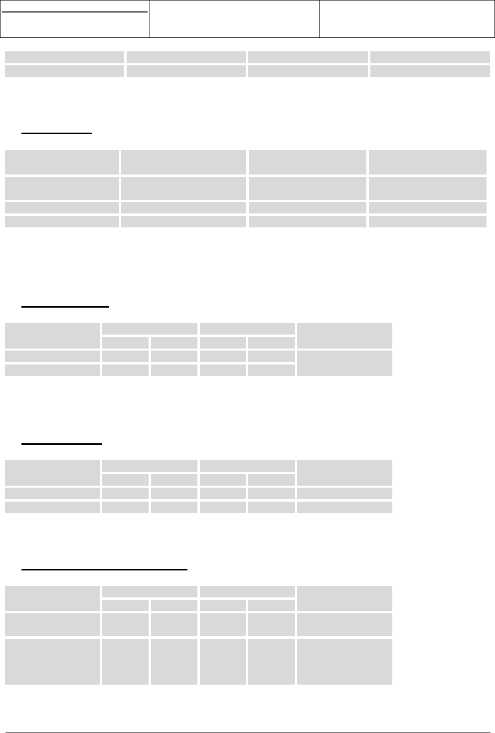
s
e
Centre de Saint Christophe - URD 37
TELEPHONIE MOBILE
MOBILE PHONES
Ref. : SCT TMO MASV2 SPEC 14 M
Date : 04/03/03
E All rights reserved. Reproduction and disclosure prohibited Page 40
MO130 module for mobile applications
This document contains information on a product under development. SAGEM reserves the right to change or discontinue this product
without notice.
VCHARGEUR Charger voltage 0V 16V
Tchstart Charge start up timer 8s 16s
6.12 RESET
TESTRESETZ has the following characteristics:
Signal Min Max Remarks
VL (V) -0.5 +0.495 Pull up
Protection
VH (V) +1.365 +2.15
Treset (ms) 65 -
NB: The reset signal resets all the system including backup.
6.13 SPARE IO
CMDSW1/2 have the following characteristics:
VL (V) VH (V)Signal
Min Max Min Max
Remarks
Input -0.5 +0.8 +2.0 +3.2
Output -+0.6 +2.4 -
Protections
Iout max = 4mA
6.14 CLOCKS
CLK13M and CLK32K have the following characteristics:
VL (V) VH (V)Signal
Min Max Min Max
Remarks
CLK13M (out) -+0.6 +2.4 -
CLK32K (out) -+0.4 +1.6 -
6.15 PARALLEL INTERFACE
D<0..15>, A<0..6>, OE*, RW*, CS2, CS3 have the following characteristics:
VL (V) VH (V)Signal
Min Max Min Max
Remarks
Input
D<0..15>
-0.5 +0.8 +2.0 +3.2
Output
D<0..15>, A<0..6>,
RW*, OE*, CS2,
CS3
-+0.6 +2.4 -
NB: The maximum capacitance acceptable on each signal of the parallel interface is 25pF (including copper
line capacitance, connectors capacitance…).
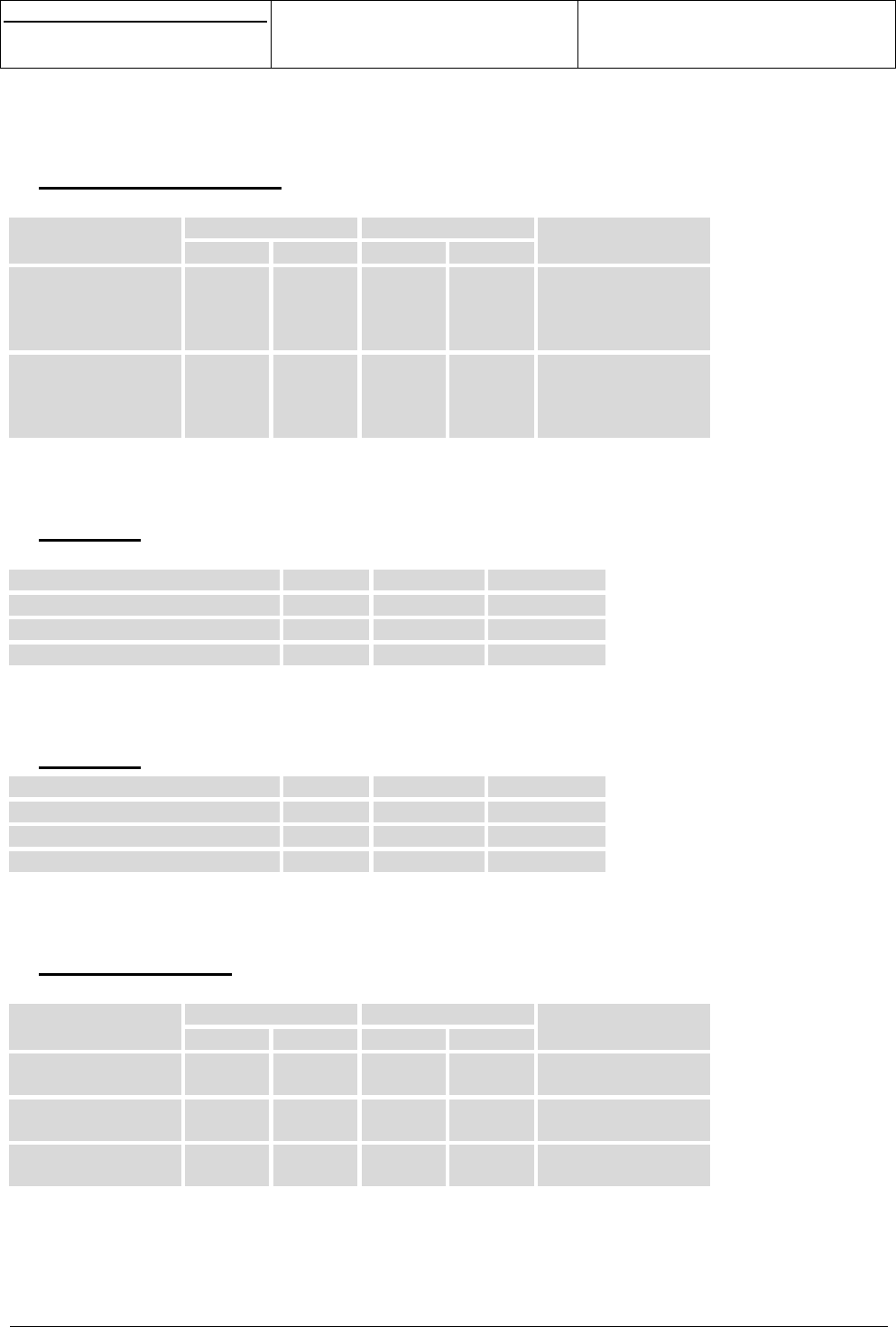
s
e
Centre de Saint Christophe - URD 37
TELEPHONIE MOBILE
MOBILE PHONES
Ref. : SCT TMO MASV2 SPEC 14 M
Date : 04/03/03
E All rights reserved. Reproduction and disclosure prohibited Page 41
MO130 module for mobile applications
This document contains information on a product under development. SAGEM reserves the right to change or discontinue this product
without notice.
6.16 JTAG INTERFACE
TCLK, TMS, TDI, TDODIGIT, TDIANALOG, NBSCAN, NEMU0, NEMU1 have the following characteristics:
VL (V) VH (V)Signal
Min Max Min Max
Remarks
Input
TCLK, TMS, TDI,
TDIANALOG,
NBSCAN
-0.5 +0.8 +2.0 +3.2
Output
TDODIGIT,
TDOANALOG,
NEMU0, NEMU1
-+0.6 +2.4 -
6.17 DAC
Recommended load on pin DAC : 30pF max // 10Kohms min
Parameter Min Typ Max
Resolution -10 bits -
Output voltage with code max 2.0V 2.2V 2.4V
Output voltage with code min 0.18V 0.24V 0.3V
6.18 ADC
Parameter Min Typ Max
Resolution -10 bits -
Input range 0 - 1.75V
Input resistance -5.7Kohms -
6.19 INTERRUPTS
ITFLAP, ITDATA and CINT have the following characteristics :
VL (V) VH (V)Signal
Min Max Min Max
Remarks
ITFLAP -0.5 +0.8 +2.0 +3.2 Pull up
Digital port
ITDATA -0.5 +0.8 +2.0 +3.2 Pull up
Digital port
CINT -0.5 +0.8 +2.0 +3.2 Pull down
Digital port
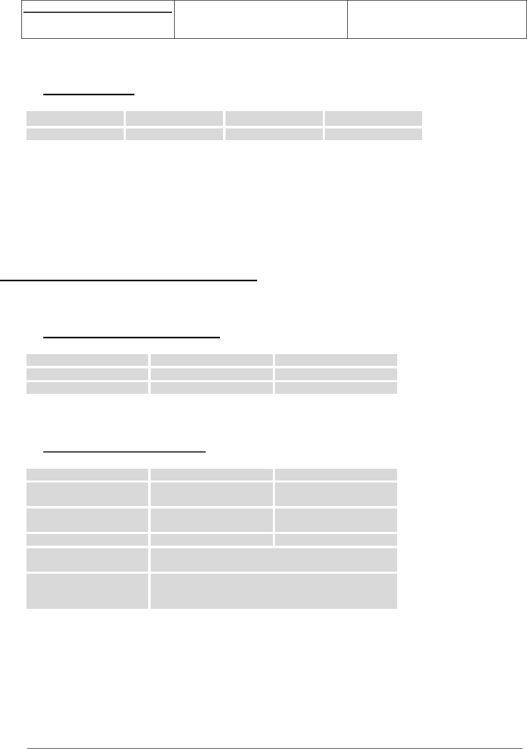
s
e
Centre de Saint Christophe - URD 37
TELEPHONIE MOBILE
MOBILE PHONES
Ref. : SCT TMO MASV2 SPEC 14 M
Date : 04/03/03
E All rights reserved. Reproduction and disclosure prohibited Page 42
MO130 module for mobile applications
This document contains information on a product under development. SAGEM reserves the right to change or discontinue this product
without notice.
6.20 VBACKUP
Signal Min Max Remarks
VBACKUP +2.2V +3.2V Protection
If no external backup is supplied, VBACKUP has to be connected to VBAT.
With external BACKUP:
- if VBAT < VBACKUP, internal RTC is supplied by VBACKUP.
- if VBAT > VBACKUP, internal RTC is supplied by VBAT.
Without external VBACKUP (VBACKUP input connected to VBAT)
- if VBAT > 2.2V, internal RTC is supplied by VBAT.
- if VBAT < 2.2V, internal RTC is not supplied.
7. ENVIRONMENTAL SPECIFICATION
7.1 OPERATING CONDITIONS
Parameter Min Max
Ambient temperature -10°C +55°C
Supply voltage VBAT +3.45V +5V
7.2 CLIMATIC CONDITIONS
Parameter Min Max
Ambient temperature
Normal range
-10°C +55°C
Ambient temperature
Extended range
-20°C +70°C
Storage temperature -40°C +85°C
Long damp heat
Operating conditions
Tested at +60°C, 95% RH during 504 hours
Short damp heat
Storage and
transportation conditions
Tested at +40°C, 95% RH during 96 hours
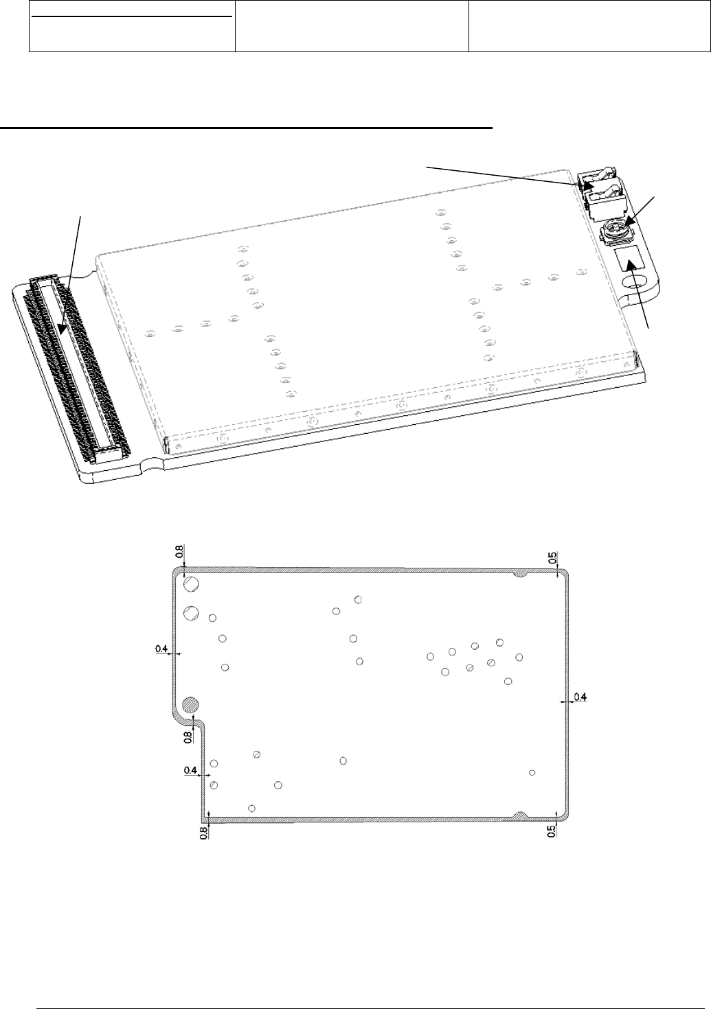
s
e
Centre de Saint Christophe - URD 37
TELEPHONIE MOBILE
MOBILE PHONES
Ref. : SCT TMO MASV2 SPEC 14 M
Date : 04/03/03
E All rights reserved. Reproduction and disclosure prohibited Page 43
MO130 module for mobile applications
This document contains information on a product under development. SAGEM reserves the right to change or discontinue this product
without notice.
8. MECHANICAL SPECIFICATION WITH CONNECTOR
Figure 17
MO130
A
VX Board to Board connecto
r
JST 2 way stacker assembly Murata coaxial
connection
Pad for antenna
connection
120
1
60 61
1
2
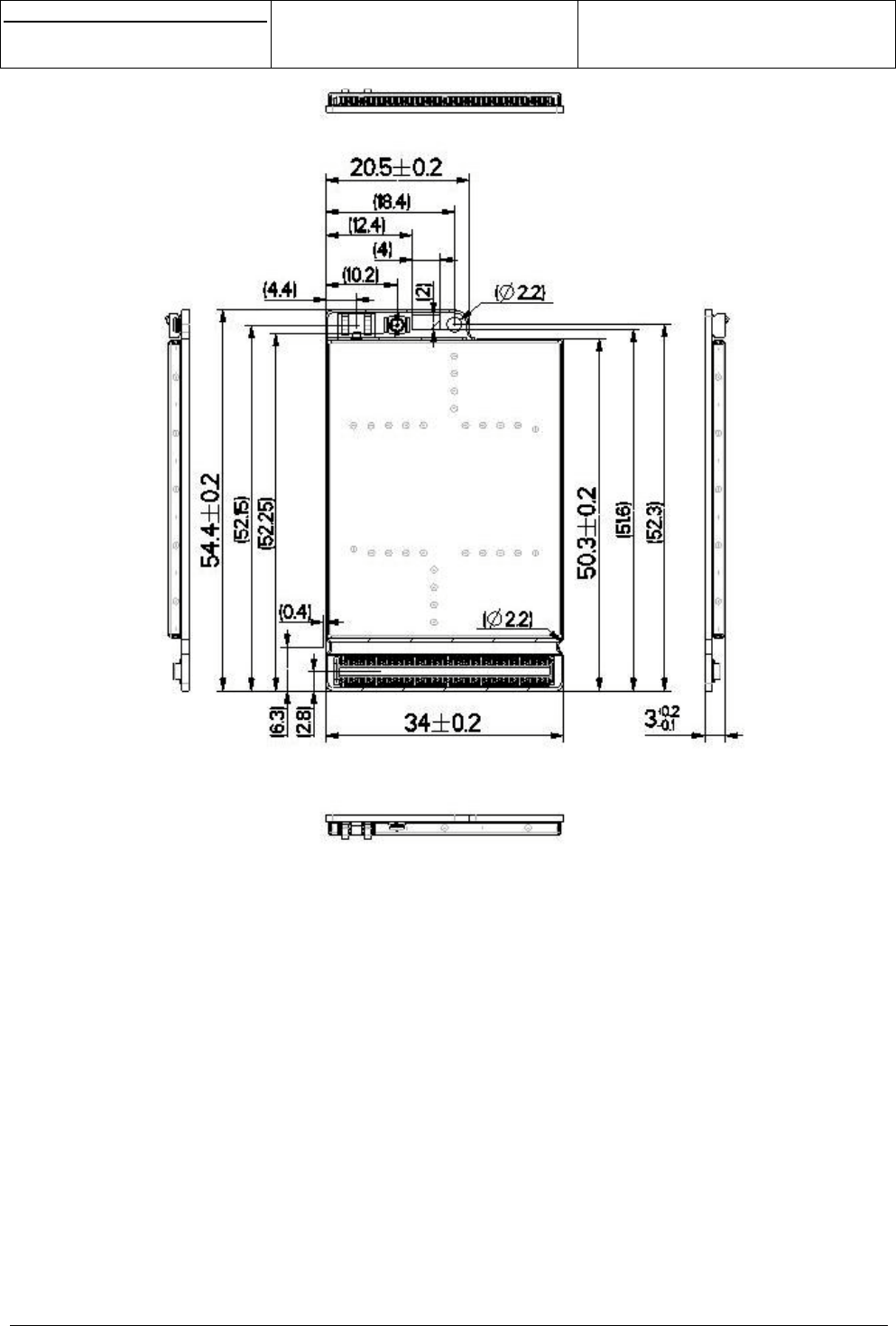
s
e
Centre de Saint Christophe - URD 37
TELEPHONIE MOBILE
MOBILE PHONES
Ref. : SCT TMO MASV2 SPEC 14 M
Date : 04/03/03
E All rights reserved. Reproduction and disclosure prohibited Page 44
MO130 module for mobile applications
This document contains information on a product under development. SAGEM reserves the right to change or discontinue this product
without notice.
Figure 18
MO130 dimensions
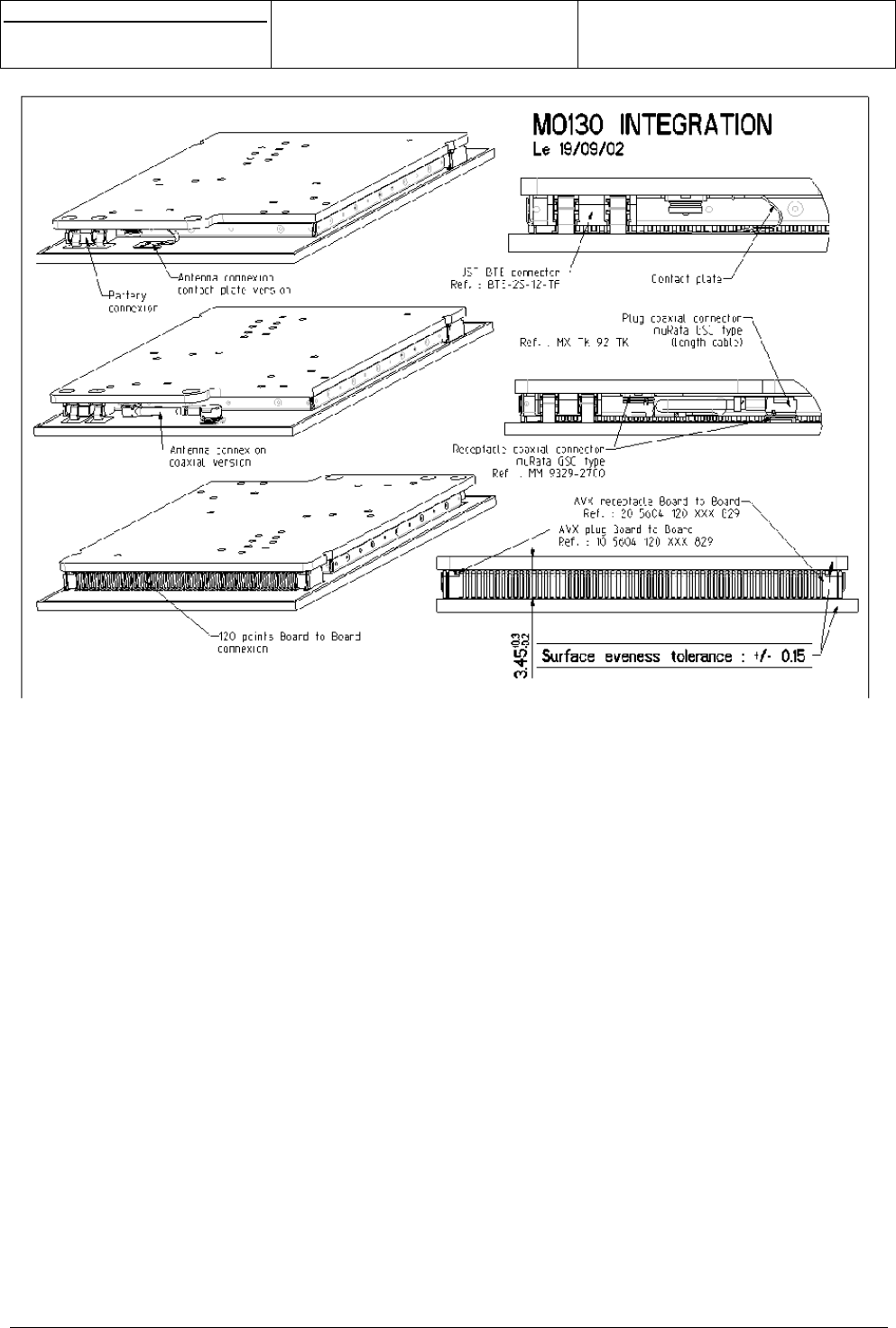
s
e
Centre de Saint Christophe - URD 37
TELEPHONIE MOBILE
MOBILE PHONES
Ref. : SCT TMO MASV2 SPEC 14 M
Date : 04/03/03
E All rights reserved. Reproduction and disclosure prohibited Page 45
MO130 module for mobile applications
This document contains information on a product under development. SAGEM reserves the right to change or discontinue this product
without notice.
Figure 19
MO130 connection to a mother board
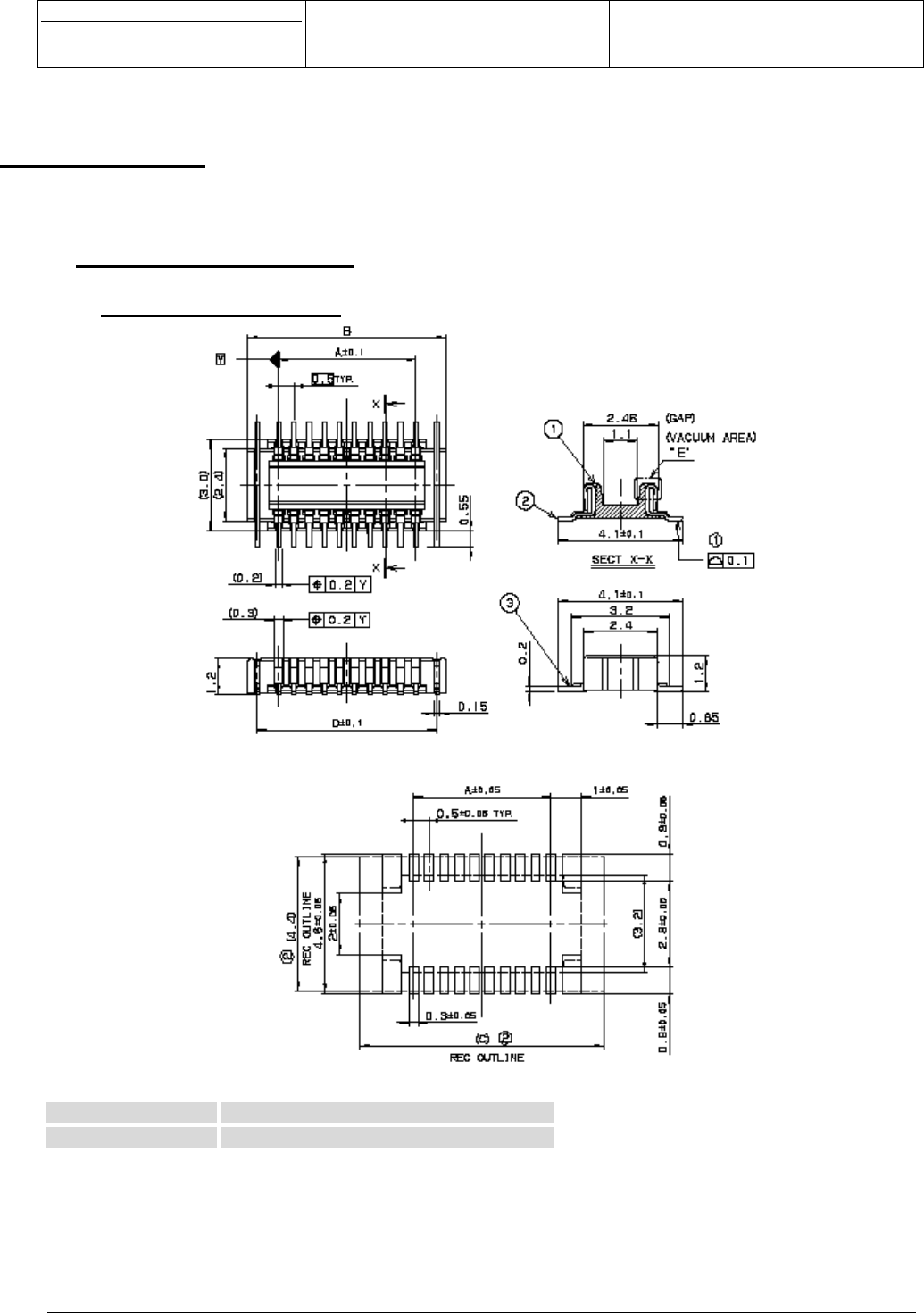
s
e
Centre de Saint Christophe - URD 37
TELEPHONIE MOBILE
MOBILE PHONES
Ref. : SCT TMO MASV2 SPEC 14 M
Date : 04/03/03
E All rights reserved. Reproduction and disclosure prohibited Page 46
MO130 module for mobile applications
This document contains information on a product under development. SAGEM reserves the right to change or discontinue this product
without notice.
9. INTEGRATION
9.1 120 PINS CONNECTOR
9.1.1 MO130 connector
Recommended PC Board Mounting pattern:
Dimensions and references:
Pin Number Reference
120 AVX 10 5604 120 212 829
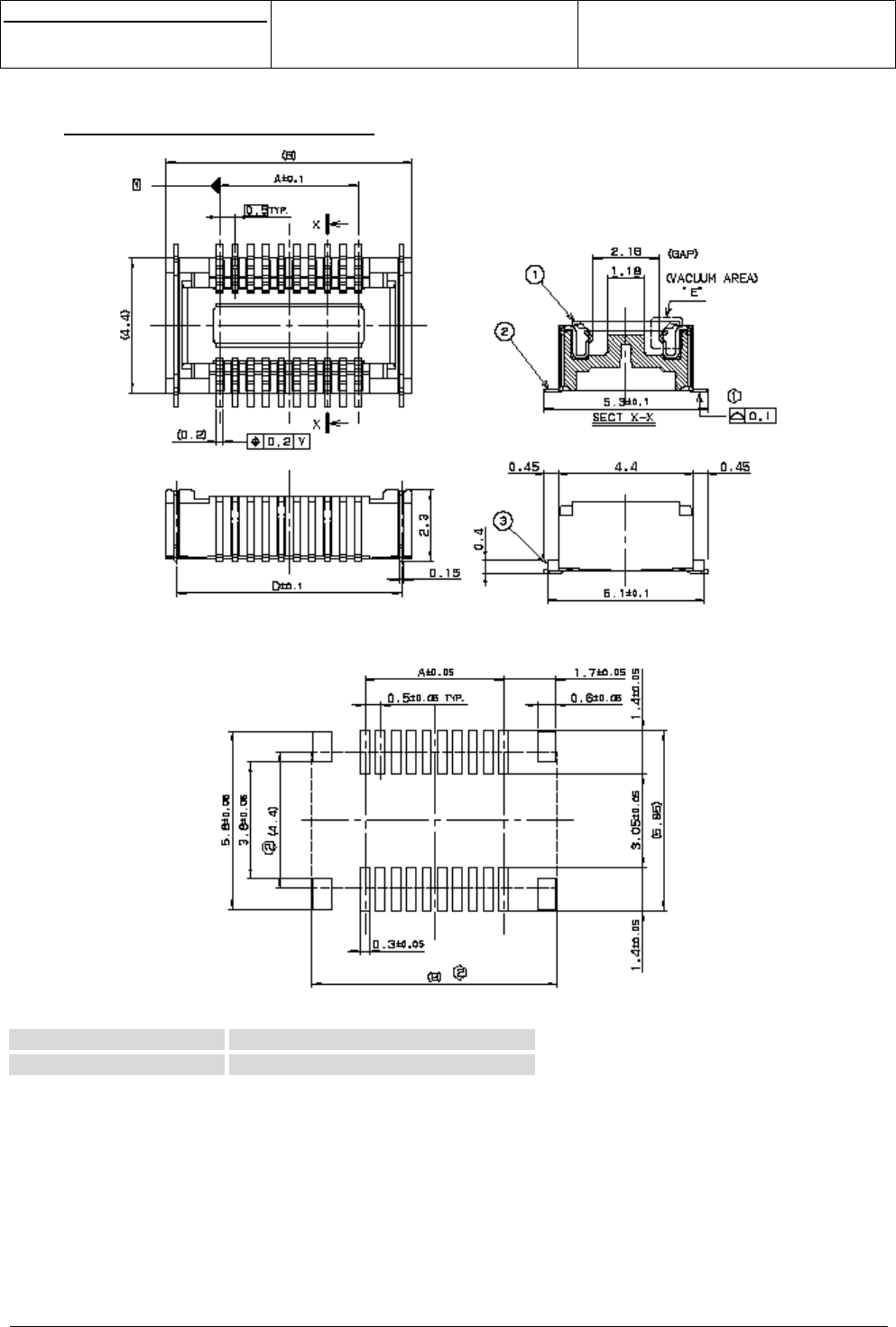
s
e
Centre de Saint Christophe - URD 37
TELEPHONIE MOBILE
MOBILE PHONES
Ref. : SCT TMO MASV2 SPEC 14 M
Date : 04/03/03
E All rights reserved. Reproduction and disclosure prohibited Page 47
MO130 module for mobile applications
This document contains information on a product under development. SAGEM reserves the right to change or discontinue this product
without notice.
9.1.2 Mother board connector
Recommended PC Board Mounting pattern:
Dimensions and references:
Pin Number References
120 AVX 20 5604 120 222 829
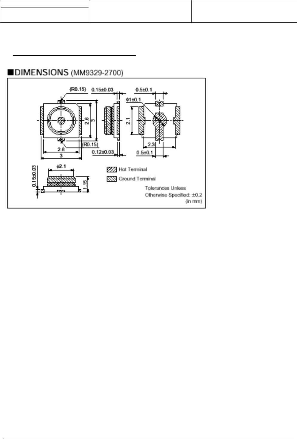
s
e
Centre de Saint Christophe - URD 37
TELEPHONIE MOBILE
MOBILE PHONES
Ref. : SCT TMO MASV2 SPEC 14 M
Date : 04/03/03
E All rights reserved. Reproduction and disclosure prohibited Page 48
MO130 module for mobile applications
This document contains information on a product under development. SAGEM reserves the right to change or discontinue this product
without notice.
9.2 MO130 ANTENNA CONNECTOR
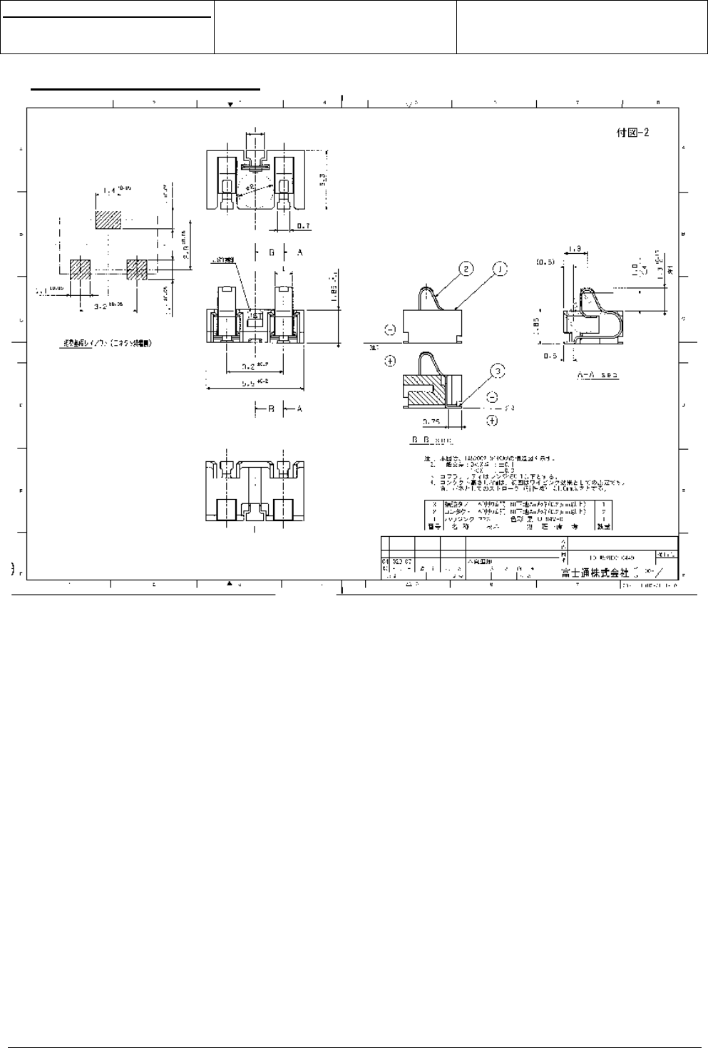
s
e
Centre de Saint Christophe - URD 37
TELEPHONIE MOBILE
MOBILE PHONES
Ref. : SCT TMO MASV2 SPEC 14 M
Date : 04/03/03
E All rights reserved. Reproduction and disclosure prohibited Page 49
MO130 module for mobile applications
This document contains information on a product under development. SAGEM reserves the right to change or discontinue this product
without notice.
9.3 BATTERY CONNECTOR
s
e
Centre de Saint Christophe - URD 37
TELEPHONIE MOBILE
MOBILE PHONES
Ref. : SCT TMO MASV2 SPEC 14 M
Date : 04/03/03
E All rights reserved. Reproduction and disclosure prohibited Page 50
MO130 module for mobile applications
This document contains information on a product under development. SAGEM reserves the right to change or discontinue this product
without notice.
ANNEXE 1 : Reference sensitivity level
The min reference guaranteed sensitivity is:
The sensitivity level is defined as the input level for which class II bits RBER/FER don’t exceed 2.4%
This minimum sensitivity shall be :
GSM 900 MS: -105 dBm max
DCS 1800 MS: -105 dBm max
Notes :
This min sensitivity value is guaranteed at 25°C and under static conditions.
Test Conditions :
Measurement is performed with :
A flexible coaxial cable equipped with a GSC connector.
A SMA-FSC adapter
A GSM tester
GSM testor
GSC Cable + SMA-FSC Adapter
RF output Murata GSC
connector
Module
Faraday Chamber
Notes: Insertion loss of the cable is removed.
s
e
Centre de Saint Christophe - URD 37
TELEPHONIE MOBILE
MOBILE PHONES
Ref. : SCT TMO MASV2 SPEC 14 M
Date : 04/03/03
E All rights reserved. Reproduction and disclosure prohibited Page 51
MO130 module for mobile applications
This document contains information on a product under development. SAGEM reserves the right to change or discontinue this product
without notice.
ANNEXE 2 : IO description
IO name Type
DAIRST Digital bi directional buffer (IDI041/OUK431)
DAIOUT Digital bi directional buffer (IDI041/OUK431)
DAIIN Digital bi directional buffer (IDI041/OUK431). Pull-down
DAICLK Digital bi directional buffer (IDI041/OUI431). Pull-down
SWANTANT Digital output buffer (OUO231)
CMDSW1 Digital bi directional buffer (IDI041/OUO431)
CMDSW2 Digital bi directional buffer (IDI041/OUO431)
ITFLAP Digital bi directional IO with interrupt capability. Pull up
ITDATA Digital bi-directional IO with interrupt capability. Pull up
CINT Pull down
BACKKEY Power open drain
BACKLCD Power open drain or Digital bi directional IO
LEDR_BUZ Digital output buffer (OUK831)
LEDG Digital output buffer (OUK431)
RSLCD Digital bi directional buffer (IDI041/OUO431)
RESETLCD* Digital bi directional buffer (IDI041/OUO431). Pull-down
ALIMLCD Power supply output
DIMIW Digital bi directional buffer (IDI041/OUO431)
DOMIW Digital output buffer (OUK431)
CKMIW Digital output buffer (OUI431)
R1 Digital bi directional buffer (IDI041/OUO231)
R2 Digital bi directional buffer (IDI041/OUO231)
R3 Digital bi directional buffer (IDI041/OUO231)
R4 Digital bi directional buffer (IDI041/OUO231)
R5 Digital bi directional buffer (IDI041/OUO231)
C1 Digital bi directional buffer (IDI041/OUO431)
C2 Digital bi directional buffer (IDI041/OUO431)
C3 Digital bi directional buffer (IDI041/OUO431)
C4 Digital bi directional buffer (IDI041/OUO431)
C5 Digital bi directional buffer (IDI041/OUO431)
SIMVCC Power supply output
SIMRST Digital output
SIMCLK Digital output
SIMIO Digital bi directional buffer
SIMCD Digital bi directional buffer (IDI091/OUO431). Pull-down
BFTXP Analog audio input
BFTXN Analog audio input
BFRXP power audio output
BFRXN power audio output
HPP High/Mean power audio output
HPN High power audio output
LPHP Mean power audio output
HPIN Analog audio input
MICP Analog audio input
MICN Analog audio input

s
e
Centre de Saint Christophe - URD 37
TELEPHONIE MOBILE
MOBILE PHONES
Ref. : SCT TMO MASV2 SPEC 14 M
Date : 04/03/03
E All rights reserved. Reproduction and disclosure prohibited Page 52
MO130 module for mobile applications
This document contains information on a product under development. SAGEM reserves the right to change or discontinue this product
without notice.
CMDVIB Power open drain
DISPI Digital input buffer (IDI041). Pull-down.
DOSPI Digital output buffer (OUK431)
ENSPI1 Digital bi directional buffer (IDI041/OUK431)
CLKSPI Digital output buffer (OUO231)
DCD Digital bi directional buffer (IDI041/OUK431). Pull-up
DTR Digital bi directional buffer (IDI091/OUK831). Pull-up
RI Open drain. Pull up
DSR Digital bi directional buffer (IDI041/OUK431)
RTS Digital bi directional buffer (IDI091/OUO231). Pull-up
CTS Digital output buffer (OUK831)
TXD2 Digital bi directional buffer (IDI041/OUK831)
RXD2 Digital input buffer (IDI091). Pull-up
TXD1 Digital output buffer (OUK831)
RXD1 Digital bi directional buffer (IDI091/OUO231). Pull-up
TXIR Digital bi directional buffer (IDI041/OUK831)
RXIR Digital bi directional buffer (IDI091/OUK431). Pull-up
CMDIRDA Digital output buffer (OUK431)
CHARGEUR Analog input
ON* Analog open drain
TESTRESETZ Digital input. Pull-up
CLK13M Digital output
CLK32K Digital output buffer (OUK431)
ADC1
DAC Analog output
D<0..15> Digital bi directional buffer (IDI041/OUI831)
A<0..6> Digital output buffer (OUI831)
CS2* Digital output buffer (OUI831)
CS3* Digital bi directional buffer (IDI041/OUI831)
RW* Digital bi directional buffer (IDI041/OUI831)
OE* Digital output buffer (OUI831)
VBACKUP Power supply input
VRIO Power supply output
VRDBB Power supply output
VRDBBDC Power supply input
V56 Power supply output
NB:
OUO231 -> Level shifter type 1 (Iol = 1mA max)
OUI431, OUK431, OUO431 -> Level shifter type 2 (Iol = 2mA max)
OUI831, OUK831 -> Level shifter type 3 (Iol = 4mA max)
----
END OF DOCUMENT