Sagem Wireless OT1X9P52 GSM 900/1900 Mobile Phone User Manual
Sagem Wireless GSM 900/1900 Mobile Phone
UserManual.wiki
>
Sagem Wireless
>
OT1X9P52 User Manual
>
User Manual
Contents
1.
User Manual
2.
User Manual Addendum
User Manual
Navigation menu
Upload a User Manual
Namespaces
Wiki Guide
HTML
PDF
Info
Views
User Manual
Discussion / Help
Navigation
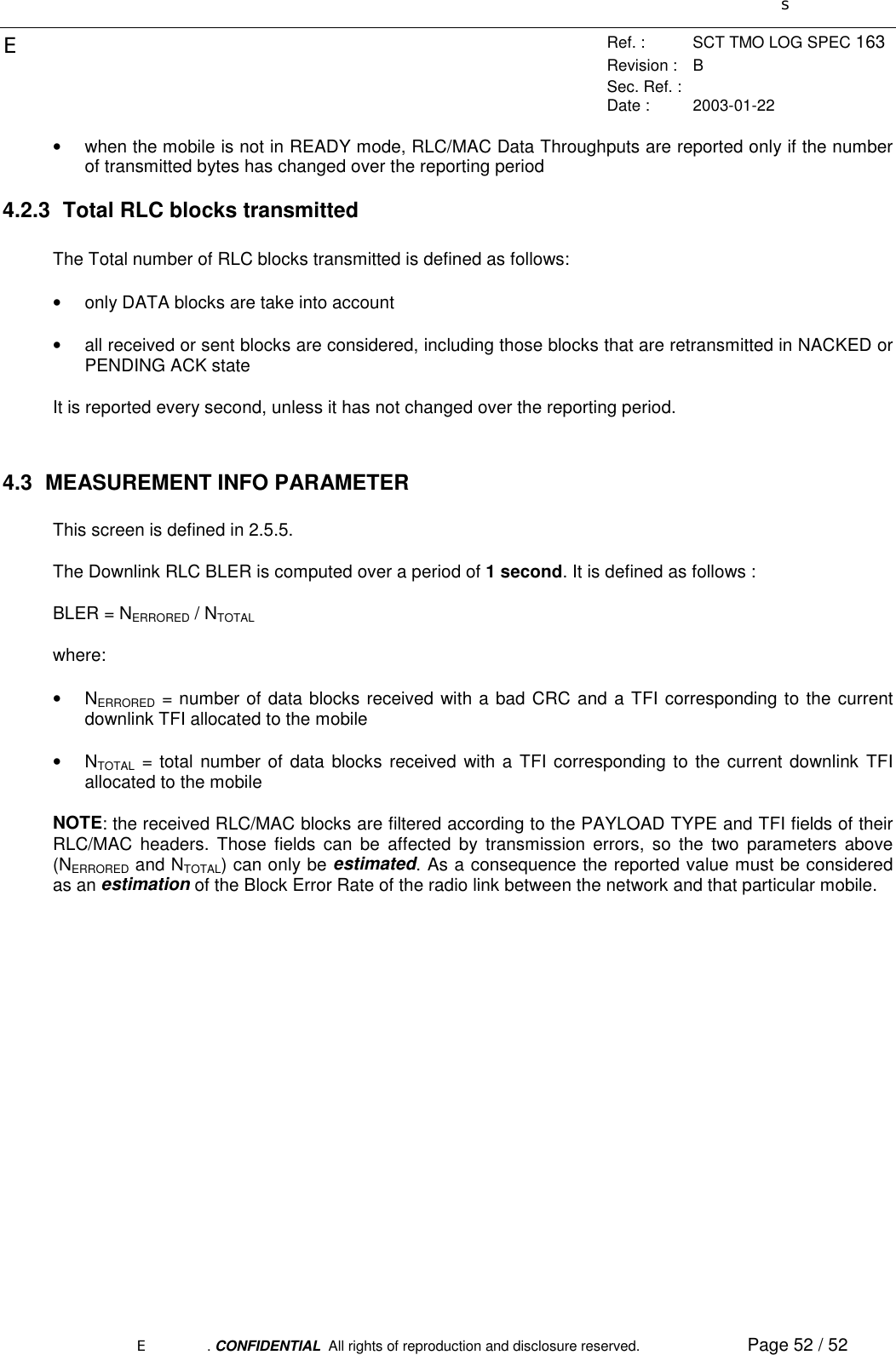
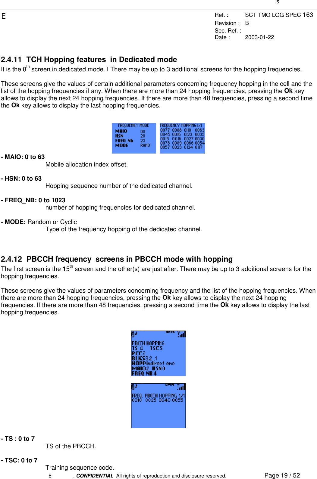
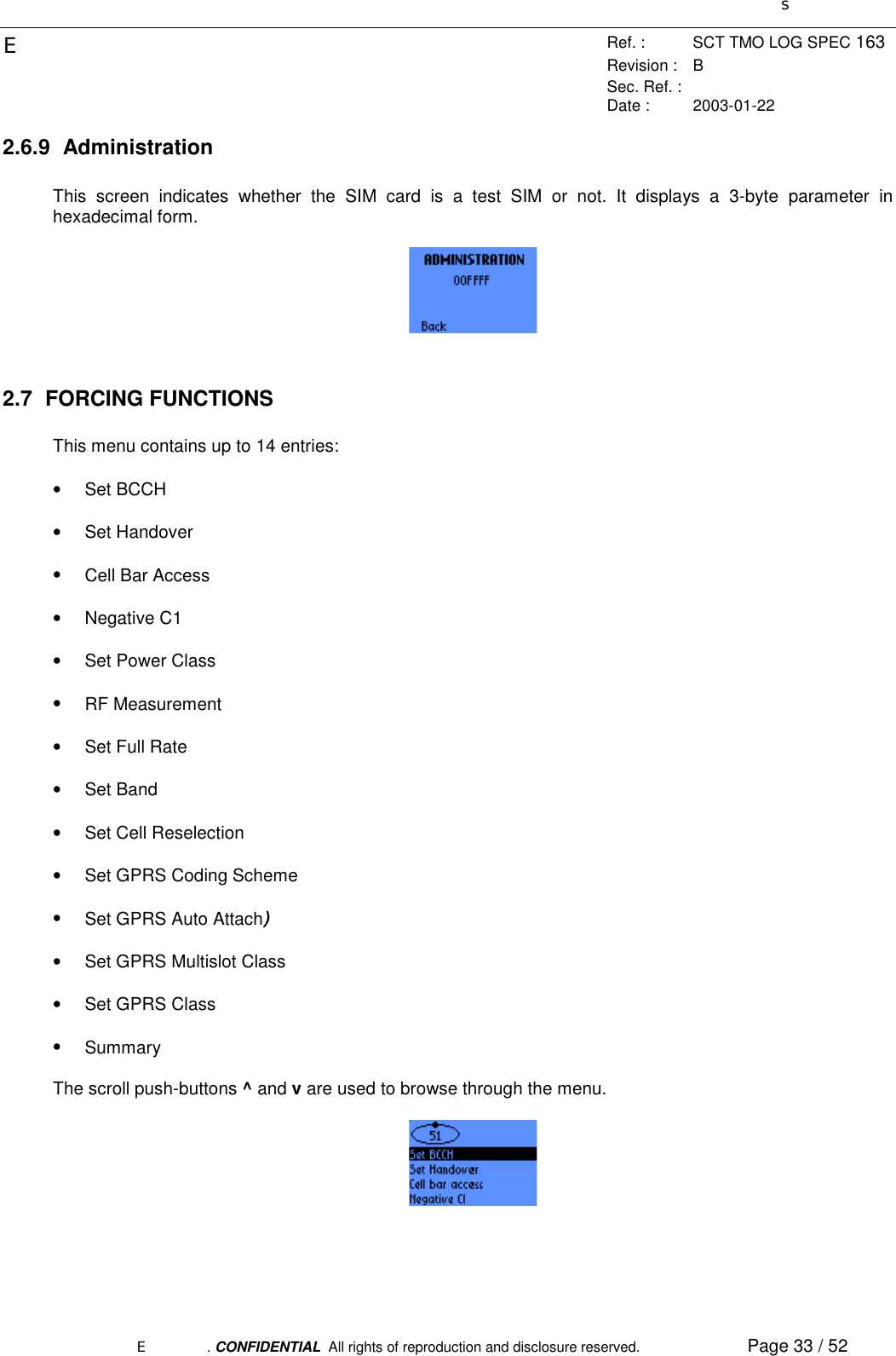
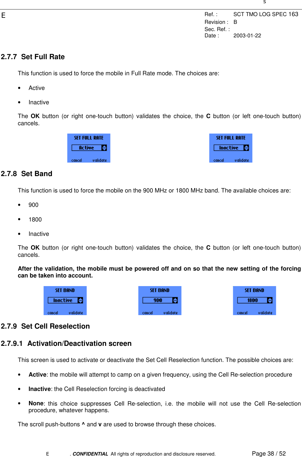
![sERef. : SCT TMO LOG SPEC 163Revision : BSec. Ref. :Date : 2003-01-22E. CONFIDENTIAL All rights of reproduction and disclosure reserved. Page 6 / 521. OBJECT1.1 INTRODUCTION.The purpose of this document is to define the MMI (Machine-Man Interface) Trace specification for the OTproduct line, some feature depends on the mobile .For each category of the trace menu, this document describes, with graphical examples, the possiblechoices that are offered to the user, along with the keypad controls used to browse through the successivescreens, to enter parameters and to modify the settings. The available categories are as follow:• MS Info: gives information related to the Mobile Station,• Network Info: displays various parameters concerning the serving and neighbouring cells,• GPRS Info (only available with OT supporting GPRS ): displays parameters related to packet dataservice,• SIM Info: allows to monitor or modify information stored in the SIM,• Forcing Functions: these functions allow to manually modify the behavior of the mobile and of thenetwork,• BCCH Scanning: performs RF power measurements on the whole band and searches for BCCHchannels,• QoS Info: displays parameters related to the provided Quality of Service,• Serial Link Setup: sets up the serial link parameters.Please note that the screens presented in this document are not contractual.1.2 REFERENCE ELEMENTS [03.64] : Serial link trace interface specification for trace mobile M42 (OT M42 STB 004E) [03.64] : Digital cellular telecommunications system (Phase 2+) ; General Packet Radio Service (GPRS) ; OverallDescription of the GPRS radio interface ; Stage 2 (Release 1997) [04.04] : Digital cellular telecommunications system (Phase 2+) ; Layer 1 ; General requirements (Release 1997) [04.07] : Digital cellular telecommunications system (Phase 2+) ; Mobile radio interface signalling layer 3 ;General aspects (Release 1997) [04.08] : Digital cellular telecommunications system (Phase 2+) ; Mobile radio interface layer 3 specification(Release 1997)](https://usermanual.wiki/Sagem-Wireless/OT1X9P52.User-Manual/User-Guide-304017-Page-6.png)
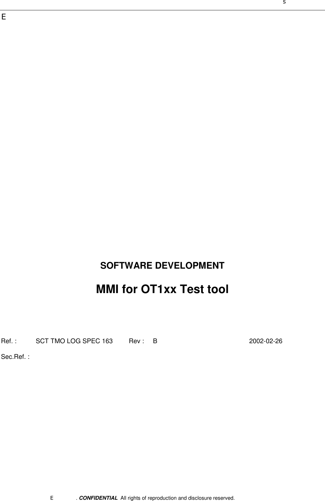
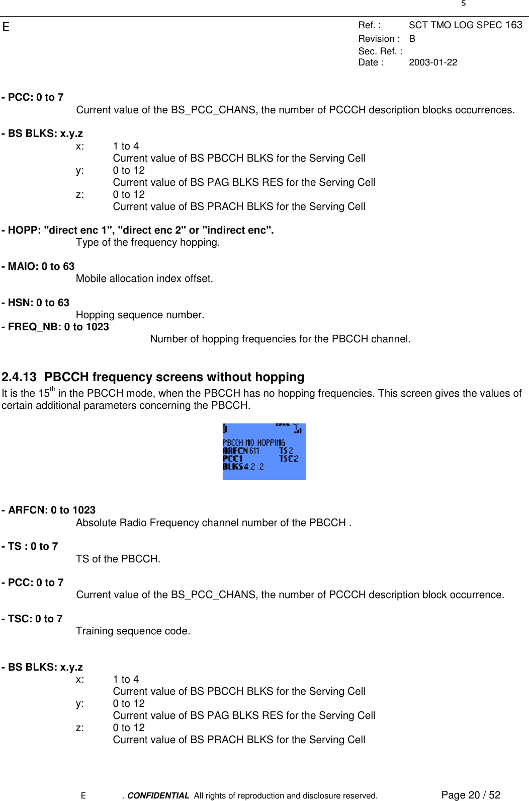
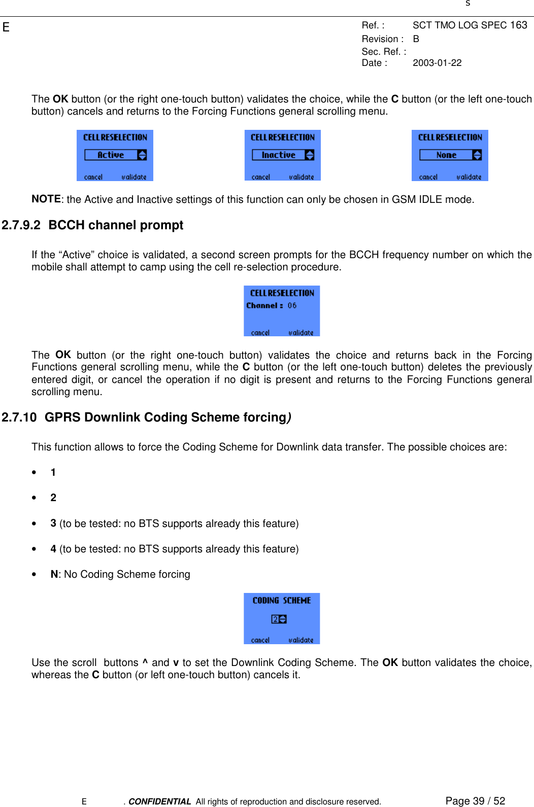
![sERef. : SCT TMO LOG SPEC 163Revision : BSec. Ref. :Date : 2003-01-22E. CONFIDENTIAL All rights of reproduction and disclosure reserved. Page 7 / 52 [04.60] : Digital cellular telecommunications system (Phase 2+) ; General Packet Radio Service (GPRS) ; MobileStation (MS) - Base Station System (BSS) interface ; Radio Link Control/ Medium Access Control (RLC\MAC)protocol (Release 1997) [04.64] : Digital cellular telecommunications system (Phase 2+) ; General Packet Radio Service (GPRS) ; MobileStation (MS) - Serving GPRS Support Node (SGSN) - Logical Link Control (LLC) layer specification (Release1997) [04.65] : Digital cellular telecommunications system (Phase 2+); General Packet Radio Service (GPRS);Subnetwork Dependent Convergence Protocol (SNDCP). [04.65] : Digital cellular telecommunications system (Phase 2+); Multiplexing and multiple access on the radiopath [04.65] : Digital cellular telecommunications system (Phase 2+); Radio transmission and reception (Release1997) [04.65] : Digital cellular telecommunications system (Phase 2+); Radio subsystem link control (Release 1997) [04.64] : Digital cellular telecommunications system (Phase 2+); General Packet Radio Service (GPRS); MobileStation (MS) supporting GPRS (Release 1997) [04.64] : Digital cellular telecommunications system (Phase 2+); Specification of the Subscriber Identity Module -Mobile Equipment (SIM - ME) interface](https://usermanual.wiki/Sagem-Wireless/OT1X9P52.User-Manual/User-Guide-304017-Page-7.png)
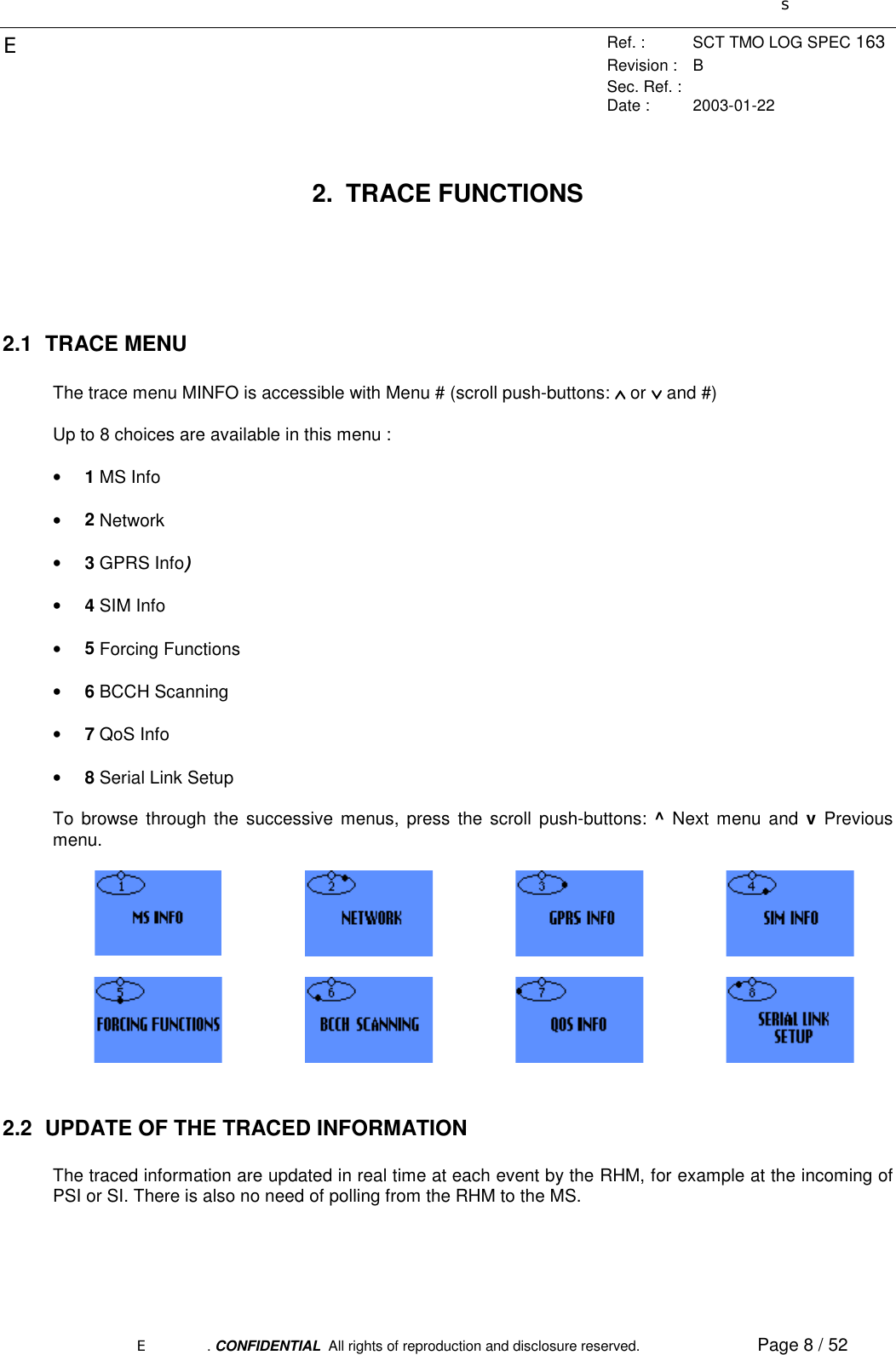
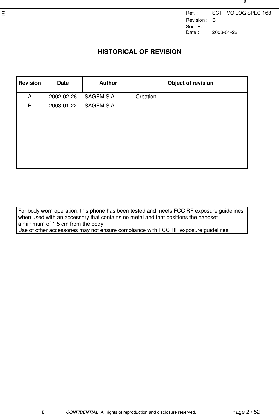
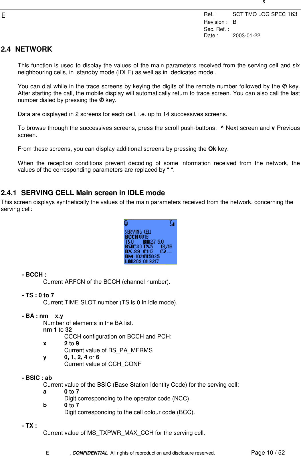
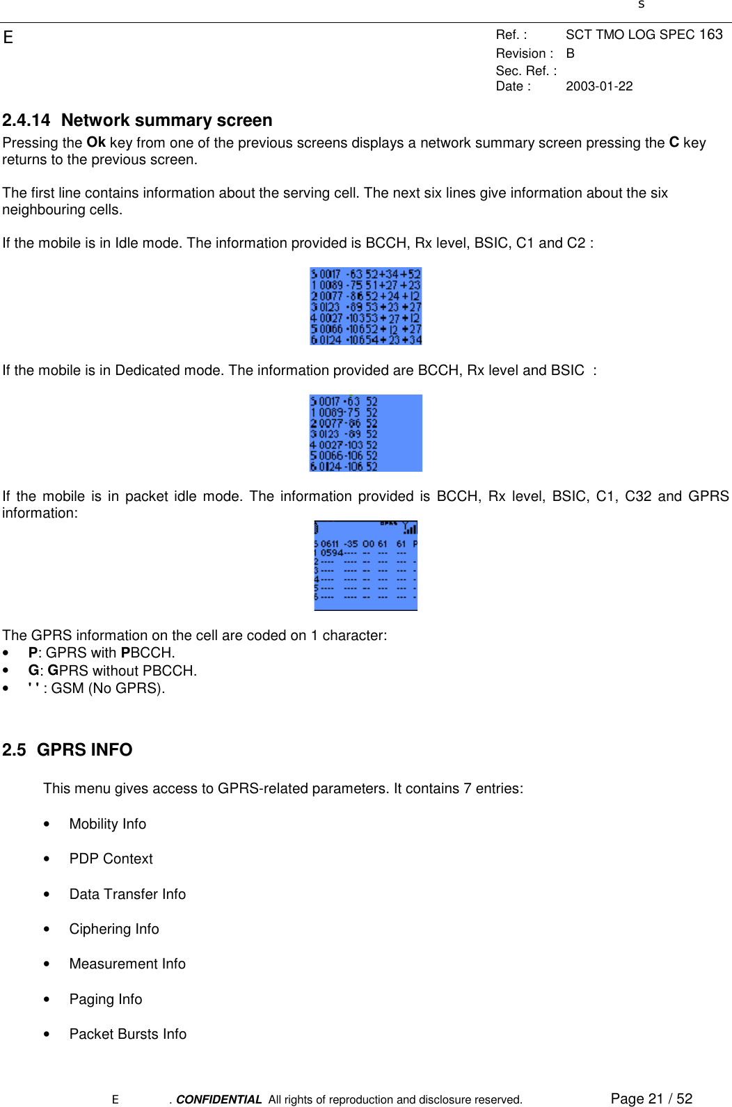
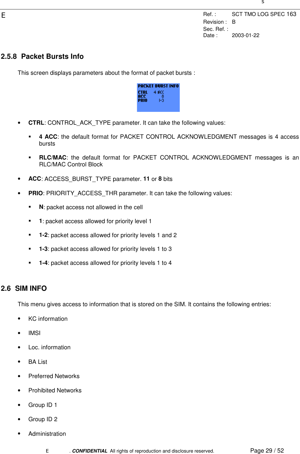
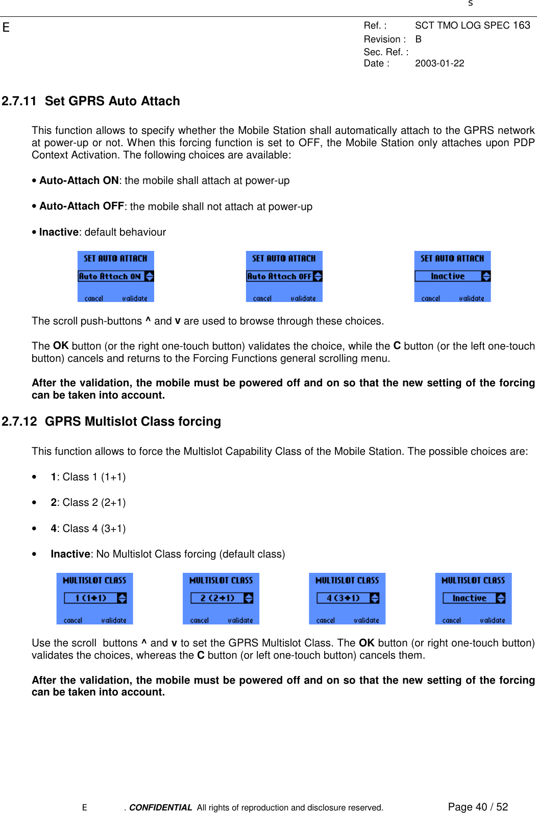
![sERef. : SCT TMO LOG SPEC 163Revision : BSec. Ref. :Date : 2003-01-22E. CONFIDENTIAL All rights of reproduction and disclosure reserved. Page 9 / 522.3 MS INFOThis menu contains 3 entries:• IMEI• TMSI/Ciphering• GPRS Class The scroll push-buttons ^ and v are used to browse through the menu.2.3.1 IMEIThis sub-menu gives the IMEI of the mobile and the software version.2.3.2 TMSI/GSM CipheringThis sub-menu gives the following information:• TMSI: 4 bytes displayed in hexadecimal• GSM Ciphering activated: Yes or No• GSM Ciphering algorithm: A5/1, A5/2, A5/3, A5/4, A5/5, A5/6 or A5/7, as defined in [04.08].2.3.3 GPRS ClassThis sub-menu gives the following information:• MS Class: gives the Mobile Station GPRS Class (B or C)• Multislot: MS class for multislot capability, as defined in [05.02]. Between parenthesis is indicated thenumber of timeslots in the Downlink and in the Uplink.](https://usermanual.wiki/Sagem-Wireless/OT1X9P52.User-Manual/User-Guide-304017-Page-9.png)
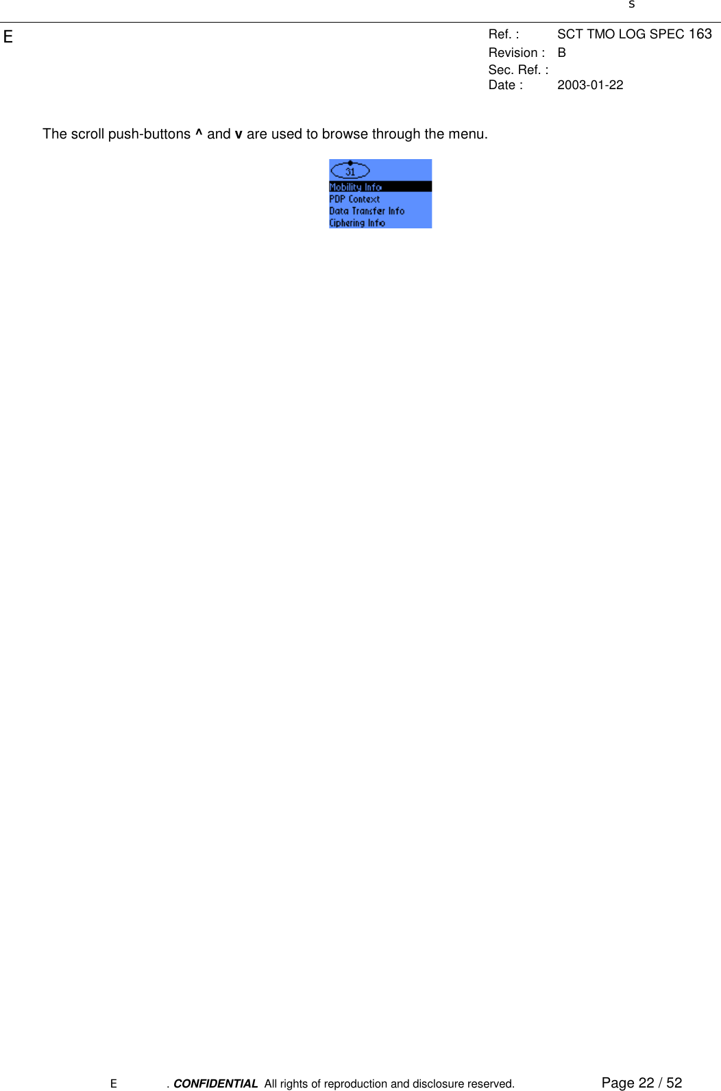
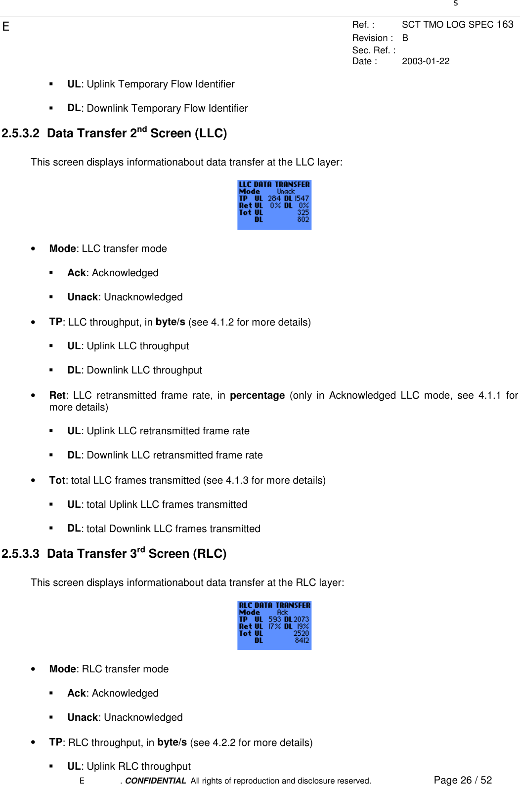
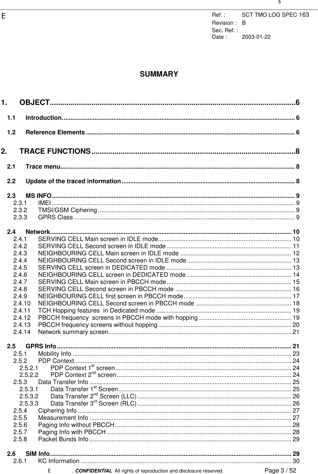
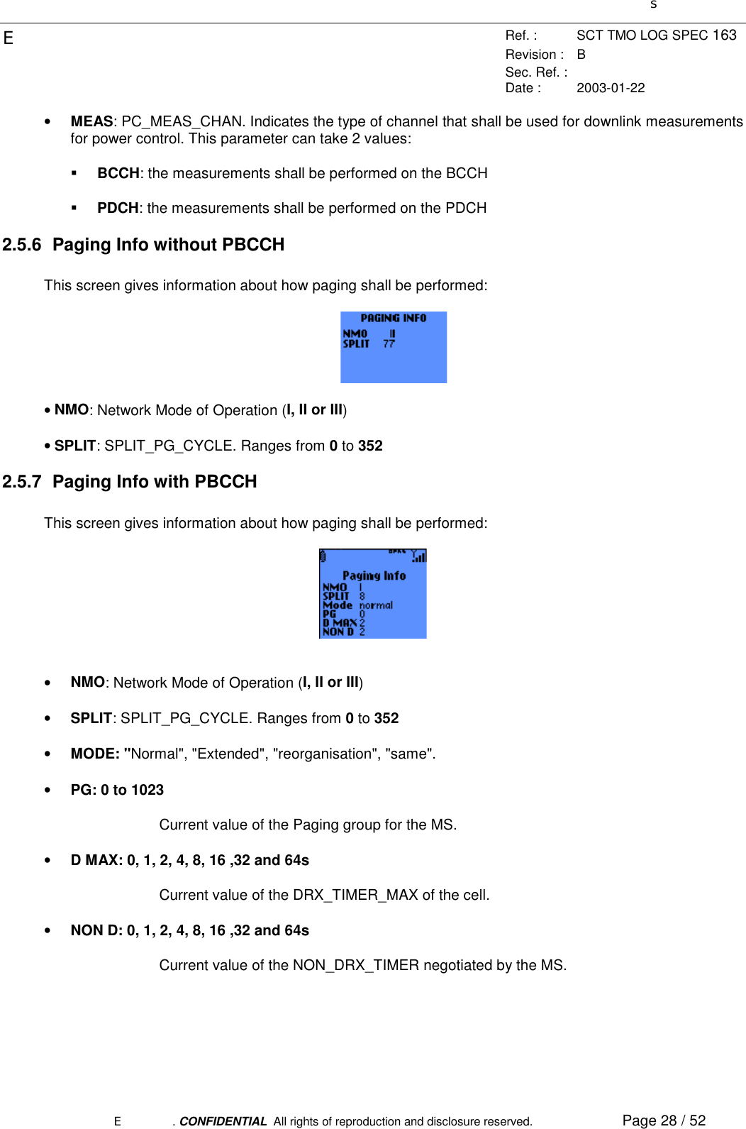
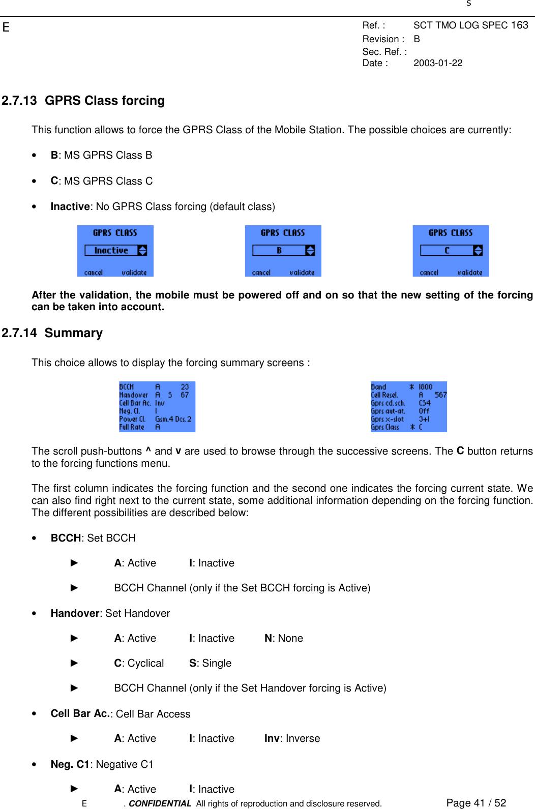
![sERef. : SCT TMO LOG SPEC 163Revision : BSec. Ref. :Date : 2003-01-22E. CONFIDENTIAL All rights of reproduction and disclosure reserved. Page 27 / 52! DL: Downlink RLC throughput• Ret: RLC retransmitted block rate, in percentage (only in Acknowledged RLC mode, see 4.2.1 formore details)! UL: Uplink RLC retransmitted block rate! DL: Downlink RLC retransmitted block rate• Tot: total RLC blocks transmitted (see 4.2.3 for more details)! UL: total Uplink RLC blocks transmitted! DL: total Downlink RLC blocks transmitted2.5.4 Ciphering InfoThis screen displays parameters related to GPRS ciphering:• GEA: indicates whether the GPRS Encryption Algorithm 1 is used or not! 1: GPRS Encryption Algorithm 1 used! No: no GPRS Encryption Algorithm used• Kc: Ciphering Key. Coded on 8 bytes, displayed in hexadecimal• KcSN: Ciphering Key Sequence Number. Coded on 3 bits, displayed in decimal2.5.5 Measurement InfoThis screen gives information about parameters measured by the MS:• CVAL: C_VALUE parameter. in dBm• SVAR: SIGN_VAR parameter. 0 to 15.75 dB², by steps of 0.25 dB²• RXQ: RXQUAL. Coded from 0 to 7, as specified in [05.08]• BLER: Block Error Rate. This parameter indicates the Block Error Rate of the radio connection. inpercentage (see 4.3 for more details)• PWR: MS Output Power. This parameter is encoded as specified in [05.05]](https://usermanual.wiki/Sagem-Wireless/OT1X9P52.User-Manual/User-Guide-304017-Page-27.png)
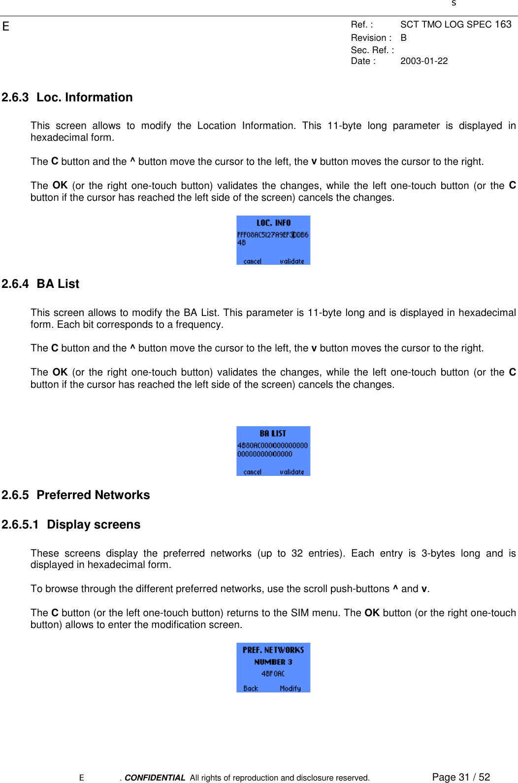
![sERef. : SCT TMO LOG SPEC 163Revision : BSec. Ref. :Date : 2003-01-22E. CONFIDENTIAL All rights of reproduction and disclosure reserved. Page 30 / 52Use the scroll push-buttons ^ and v to browse through this menu.2.6.1 KC InformationThis screen allows to modify the KC key and the KC key sequence number. This parameters are displayedin hexadecimal form and in the same format as they are stored in the SIM (see [11.11] for more details):• The 2 rightmost digits represent the 8-bit long KC key sequence number. The actual KC key sequencenumber is encoded using the 3 Least Significant Bits.• The 16 other digits represent the 64-bit long KC keyThe C button and the ^ button move the cursor to the left, the v button moves the cursor to the right.The OK (or the right one-touch button) validates the changes, while the left one-touch button (or the Cbutton if the cursor has reached the left side of the screen) cancels the changes.2.6.2 IMSIThis screen allows to see the IMSI. This parameter is displayed in decimal form and in the same format asit is stored in the SIM (see [11.11] for more details):• The 2 leftmost digits indicate the length (in bytes) of the IMSI.• The third digit from the left is the 1st digit of the IMSI• The fourth digit from the left is related to the parity bit (see [11.11]). It should normally be equal to 1 or9.• The remaining digit are the other digit of the IMSI, but they must be inverted two by two (fifth digit fromthe left on the screen = 3nd digit of the IMSI, sixth digit from the left on the screen = 2nd digit of theIMSI, last digit on the screen = 14th digit of the IMSI)The C button and the ^ button move the cursor to the left, the v button moves the cursor to the right.](https://usermanual.wiki/Sagem-Wireless/OT1X9P52.User-Manual/User-Guide-304017-Page-30.png)
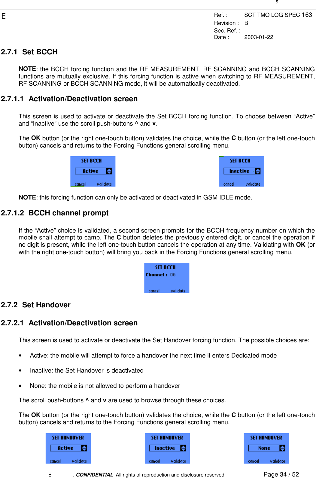
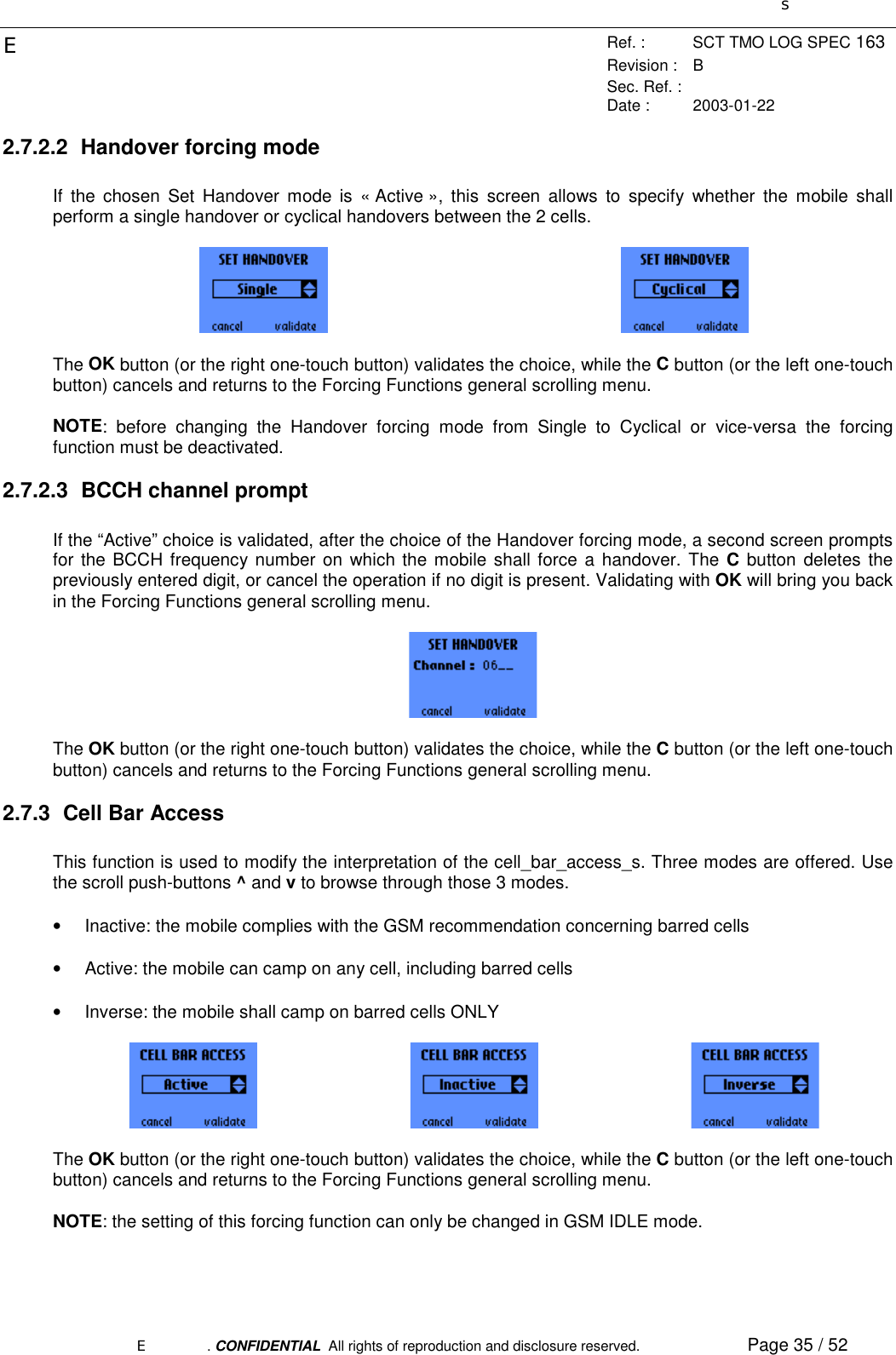
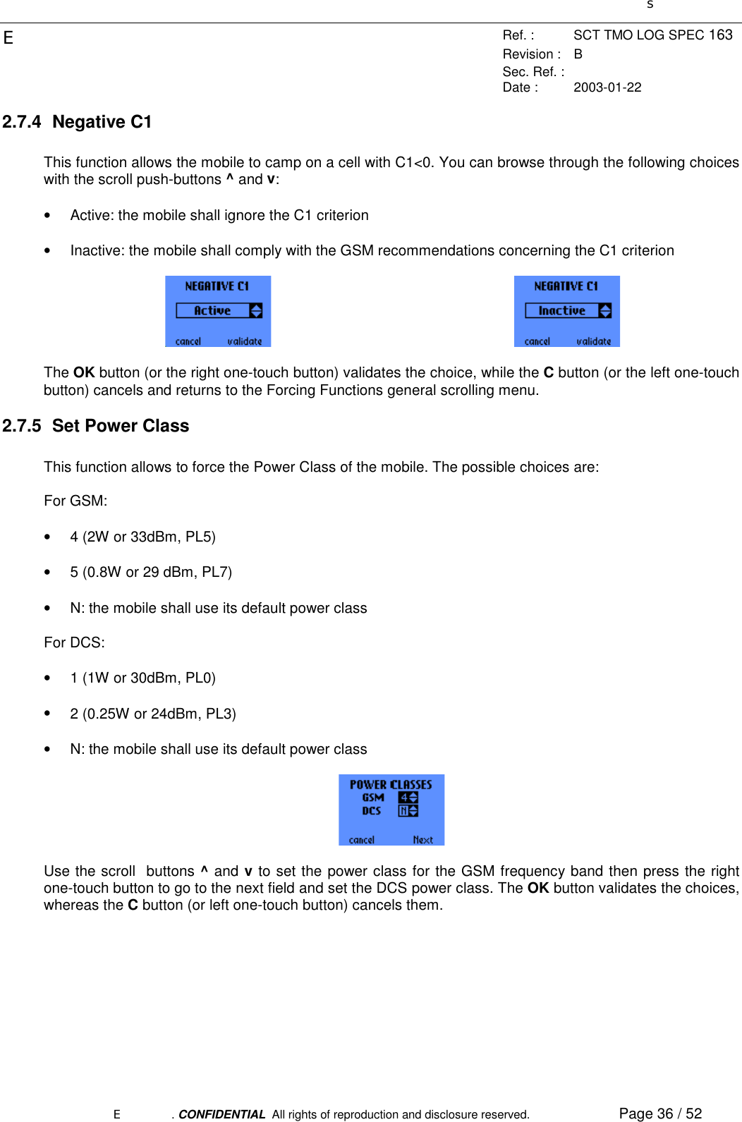
![sERef. : SCT TMO LOG SPEC 163Revision : BSec. Ref. :Date : 2003-01-22E. CONFIDENTIAL All rights of reproduction and disclosure reserved. Page 37 / 522.7.6 RF MeasurementNOTE: the BCCH forcing function and the RF MEASUREMENT function are mutually exclusive. If thisforcing function is active when activating RF MEASUREMENT, it will be automatically deactivated.2.7.6.1 Activation/Deactivation screenThis function forces the mobile to perform RF power measurements on a given frequency. You can browsethrough the following choices with the scroll push-buttons ^ and v:• Active• InactiveThe OK button (or the right one-touch button) validates the choice, while the C button (or the left one-touchbutton) cancels and returns to the Forcing Functions general scrolling menu.2.7.6.2 Frequency prompt and Field measurement screenIf the “Active” choice is validated this screen prompts for the frequency number on which the mobile shallperform measurements and displays the measurement results when the channel number has beenvalidated with the OK button (or the right one-touch button). During the measurements, the OK button (orthe right one-touch button) also allows you to stop the forcing in order to enter another channel number.2.7.6.3 Serial Link RF Measurement in progressIf the RF measurement mode was activated through the serial link of the trace mobile (see [1] for moredetails about the serial link features and protocol), this screen is displayed to notify the user that a seriallink RF Measurement is in progress. Note that this screen is displayed regardless of the current menu orthe activated functions in the MMI: it depends only on the activation of the RF Measurement functionthrough the serial link.Pressing the C button (or the left one-touch button) aborts the serial link RF Measurement function.](https://usermanual.wiki/Sagem-Wireless/OT1X9P52.User-Manual/User-Guide-304017-Page-37.png)
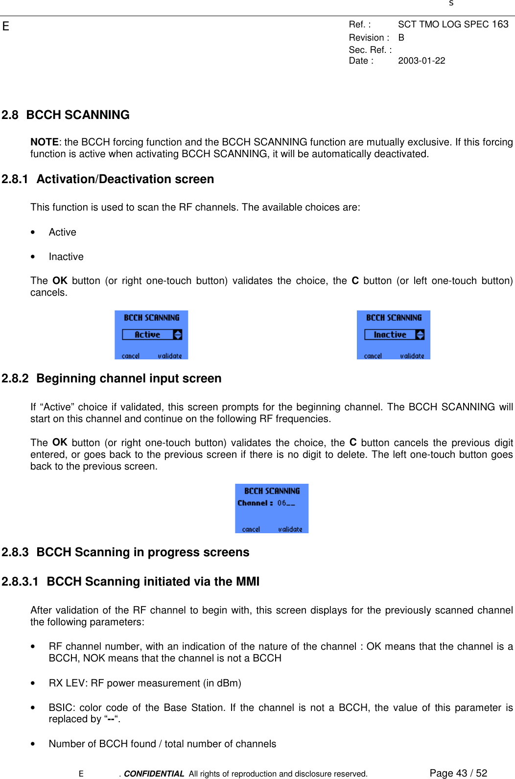
![sERef. : SCT TMO LOG SPEC 163Revision : BSec. Ref. :Date : 2003-01-22E. CONFIDENTIAL All rights of reproduction and disclosure reserved. Page 44 / 52Pressing the C button (or the left one-touch button) returns to the beginning channel input screen (see2.8.2). The OK button (or the right one-touch button) stops the scanning and displays the results of thescanning.2.8.3.2 BCCH Scanning initiated via the Serial LinkFurthermore, during a scanning that was activated through the serial link of the trace mobile (see [1] formore details about the serial link features and protocol), this screen is displayed to notify the user that aserial link BCCH scanning is in progress. Note that this screen is displayed regardless of the current menuor the activated functions in the MMI: it depends only on the activation of the Scanning function through theserial link.Pressing the C button (or the left one-touch button) aborts the serial link scanning.2.8.4 Beginning channel for results displayBefore actually displaying the results of the scanning, the mobile asks for the beginning channel number.The C button (or the left one-touch button) cancels the digit entered previously. The OK button (or rightone-touch button) validates the beginning frequency.2.8.5 BCCH Scanning results screenThis screen shows the measured parameters for every channel beginning with the channel numberpreviously entered:• RF: channel number• RXLEV: RF power measurement (in dBm). If the corresponding channel was not scanned during theprevious scan, this value is replaced by “----“.• BSIC: color code of the Base Station. If the corresponding channel is not a BCCH or was not scannedduring the previous scan, this value is replaced by “----“.To browse through the successive results screen, use the scroll push-buttons ^ and v.](https://usermanual.wiki/Sagem-Wireless/OT1X9P52.User-Manual/User-Guide-304017-Page-44.png)
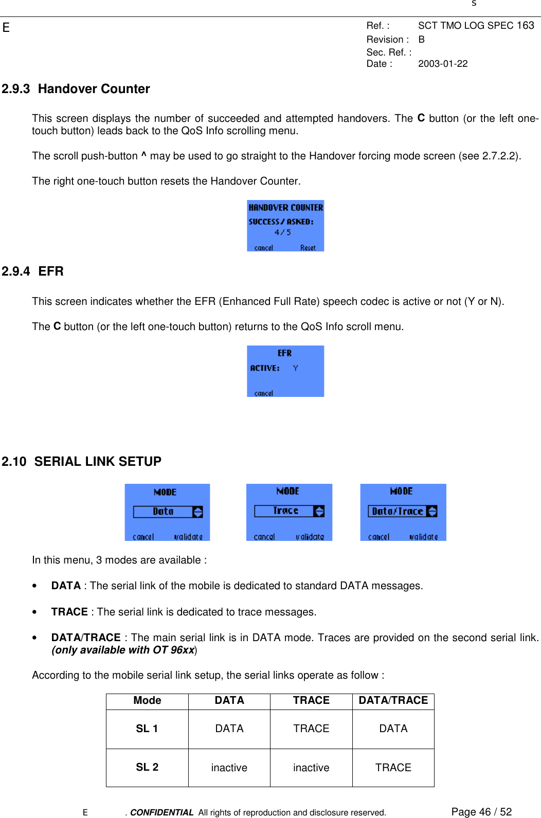
![sERef. : SCT TMO LOG SPEC 163Revision : BSec. Ref. :Date : 2003-01-22E. CONFIDENTIAL All rights of reproduction and disclosure reserved. Page 45 / 52The C button (or the left one-touch button) cancels the digit entered previously brings back to thebeginning channel screen for results display (see 2.8.4).2.9 QOS INFOThis menu contains 4 entries:• FER full• T3212• Handover Counter• EFRThe scroll push-buttons ^ and v are used to browse through the menu.2.9.1 FER fullThis function gives the FER (Frame Erasure Rate) in percentage of the speech frames erased over the lastfour measurement periods.When this value is not applicable (for instance in Idle mode), the FER value is replaced by “----“.The C button (or the left one-touch button) brings back to the QoS Info scrolling menu.2.9.2 T3212This screen displays the following parameters:• max_retrans: the maximum allowed number of retransmissions of a burst over the RACH (RandomAccess Channel) is equal to max_retrans. The displayed values are: RACH retransmission countervalue / max_retrans value. See [04.08] for more details.• T3212: the T3212 counter indicates the timeout (in decihour) value for the periodic updating. It rangesfrom 1 to 255. Inf means infinite timeout, i.e. the mobile shall not perform any periodic updating. See[04.08] for more details.The C button (or the left one-touch button) returns to the QoS Info scroll menu.](https://usermanual.wiki/Sagem-Wireless/OT1X9P52.User-Manual/User-Guide-304017-Page-45.png)
![sERef. : SCT TMO LOG SPEC 163Revision : BSec. Ref. :Date : 2003-01-22E. CONFIDENTIAL All rights of reproduction and disclosure reserved. Page 47 / 522.11 RF SCANNING IN PROGRESS SCREENThis screen indicates that the mobile is in RF Scanning mode. This mode is only available through theserial link interface of the mobile (see [1] for more details). Note that this screen is displayed regardless ofthe current menu or the activated functions in the MMI: it depends only on the activation of the RFScanning function through the serial link.Pressing the C button (or the left one-touch button) aborts the serial link RF Scanning function.](https://usermanual.wiki/Sagem-Wireless/OT1X9P52.User-Manual/User-Guide-304017-Page-47.png)