Sagem Wireless OT1X9P52 GSM 900/1900 Mobile Phone User Manual
Sagem Wireless GSM 900/1900 Mobile Phone
Contents
- 1. User Manual
- 2. User Manual Addendum
User Manual

s
E
E. CONFIDENTIAL All rights of reproduction and disclosure reserved.
SOFTWARE DEVELOPMENT
MMI for OT1xx Test tool
Ref. : SCT TMO LOG SPEC 163 Rev : B 2002-02-26
Sec.Ref. :
s
ERef. : SCT TMO LOG SPEC 163
Revision : B
Sec. Ref. :
Date : 2003-01-22
E. CONFIDENTIAL All rights of reproduction and disclosure reserved. Page 2 / 52
HISTORICAL OF REVISION
Revision Date Author Object of revision
A 2002-02-26 SAGEM S.A. Creation
B 2003-01-22 SAGEM S.A
For body worn operation, this phone has been tested and meets FCC RF exposure guidelines
when used with an accessory that contains no metal and that positions the handset
a minimum of 1.5 cm from the body.
Use of other accessories may not ensure compliance with FCC RF exposure guidelines.

s
ERef. : SCT TMO LOG SPEC 163
Revision : B
Sec. Ref. :
Date : 2003-01-22
E. CONFIDENTIAL All rights of reproduction and disclosure reserved. Page 3 / 52
SUMMARY
1. OBJECT......................................................................................................................6
1.1 Introduction........................................................................................................................................ 6
1.2 Reference Elements .......................................................................................................................... 6
2. TRACE FUNCTIONS..................................................................................................8
2.1 Trace menu......................................................................................................................................... 8
2.2 Update of the traced information..................................................................................................... 8
2.3 MS INFO.............................................................................................................................................. 9
2.3.1 IMEI .............................................................................................................................................. 9
2.3.2 TMSI/GSM Ciphering ................................................................................................................... 9
2.3.3 GPRS Class ................................................................................................................................. 9
2.4 Network............................................................................................................................................. 10
2.4.1 SERVING CELL Main screen in IDLE mode.............................................................................. 10
2.4.2 SERVING CELL Second screen in IDLE mode ......................................................................... 11
2.4.3 NEIGHBOURING CELL Main screen in IDLE mode ................................................................. 12
2.4.4 NEIGHBOURING CELL Second screen in IDLE mode............................................................. 13
2.4.5 SERVING CELL screen in DEDICATED mode ......................................................................... 13
2.4.6 NEIGHBOURING CELL screen in DEDICATED mode ............................................................. 14
2.4.7 SERVING CELL Main screen in PBCCH mode......................................................................... 15
2.4.8 SERVING CELL Second screen in PBCCH mode .................................................................... 16
2.4.9 NEIGHBOURING CELL first screen in PBCCH mode............................................................... 17
2.4.10 NEIGHBOURING CELL Second screen in PBCCH mode ........................................................ 18
2.4.11 TCH Hopping features in Dedicated mode ............................................................................... 19
2.4.12 PBCCH frequency screens in PBCCH mode with hopping ...................................................... 19
2.4.13 PBCCH frequency screens without hopping.............................................................................. 20
2.4.14 Network summary screen........................................................................................................... 21
2.5 GPRS Info......................................................................................................................................... 21
2.5.1 Mobility Info ................................................................................................................................ 23
2.5.2 PDP Context............................................................................................................................... 24
2.5.2.1 PDP Context 1st screen....................................................................................................... 24
2.5.2.2 PDP Context 2nd screen...................................................................................................... 24
2.5.3 Data Transfer Info ...................................................................................................................... 25
2.5.3.1 Data Transfer 1st Screen..................................................................................................... 25
2.5.3.2 Data Transfer 2nd Screen (LLC).......................................................................................... 26
2.5.3.3 Data Transfer 3rd Screen (RLC).......................................................................................... 26
2.5.4 Ciphering Info............................................................................................................................. 27
2.5.5 Measurement Info ...................................................................................................................... 27
2.5.6 Paging Info without PBCCH ....................................................................................................... 28
2.5.7 Paging Info with PBCCH ............................................................................................................ 28
2.5.8 Packet Bursts Info ...................................................................................................................... 29
2.6 SIM Info............................................................................................................................................. 29
2.6.1 KC Information ........................................................................................................................... 30

s
ERef. : SCT TMO LOG SPEC 163
Revision : B
Sec. Ref. :
Date : 2003-01-22
E. CONFIDENTIAL All rights of reproduction and disclosure reserved. Page 4 / 52
2.6.2 IMSI ............................................................................................................................................ 30
2.6.3 Loc. Information.......................................................................................................................... 31
2.6.4 BA List ........................................................................................................................................ 31
2.6.5 Preferred Networks .................................................................................................................... 31
2.6.5.1 Display screens................................................................................................................... 31
2.6.5.2 Modification screen ............................................................................................................. 32
2.6.6 Prohibited Networks ................................................................................................................... 32
2.6.7 Group ID 1.................................................................................................................................. 32
2.6.8 Group ID 2.................................................................................................................................. 32
2.6.9 Administration............................................................................................................................. 33
2.7 Forcing Functions ........................................................................................................................... 33
2.7.1 Set BCCH................................................................................................................................... 34
2.7.1.1 Activation/Deactivation screen............................................................................................ 34
2.7.1.2 BCCH channel prompt ........................................................................................................ 34
2.7.2 Set Handover ............................................................................................................................. 34
2.7.2.1 Activation/Deactivation screen............................................................................................ 34
2.7.2.2 Handover forcing mode....................................................................................................... 35
2.7.2.3 BCCH channel prompt ........................................................................................................ 35
2.7.3 Cell Bar Access.......................................................................................................................... 35
2.7.4 Negative C1................................................................................................................................ 36
2.7.5 Set Power Class......................................................................................................................... 36
2.7.6 RF Measurement........................................................................................................................ 37
2.7.6.1 Activation/Deactivation screen............................................................................................ 37
2.7.6.2 Frequency prompt and Field measurement screen............................................................ 37
2.7.6.3 Serial Link RF Measurement in progress............................................................................ 37
2.7.7 Set Full Rate............................................................................................................................... 38
2.7.8 Set Band..................................................................................................................................... 38
2.7.9 Set Cell Reselection................................................................................................................... 38
2.7.9.1 Activation/Deactivation screen............................................................................................ 38
2.7.9.2 BCCH channel prompt ........................................................................................................ 39
2.7.10 GPRS Downlink Coding Scheme forcing).................................................................................. 39
2.7.11 Set GPRS Auto Attach ............................................................................................................... 40
2.7.12 GPRS Multislot Class forcing..................................................................................................... 40
2.7.13 GPRS Class forcing).................................................................................................................. 41
2.7.14 Summary.................................................................................................................................... 41
2.8 BCCH Scanning ............................................................................................................................... 43
2.8.1 Activation/Deactivation screen ................................................................................................... 43
2.8.2 Beginning channel input screen ................................................................................................. 43
2.8.3 BCCH Scanning in progress screens......................................................................................... 43
2.8.3.1 BCCH Scanning initiated via the MMI................................................................................. 43
2.8.3.2 BCCH Scanning initiated via the Serial Link....................................................................... 44
2.8.4 Beginning channel for results display......................................................................................... 44
2.8.5 BCCH Scanning results screen.................................................................................................. 44
2.9 QoS Info............................................................................................................................................ 45
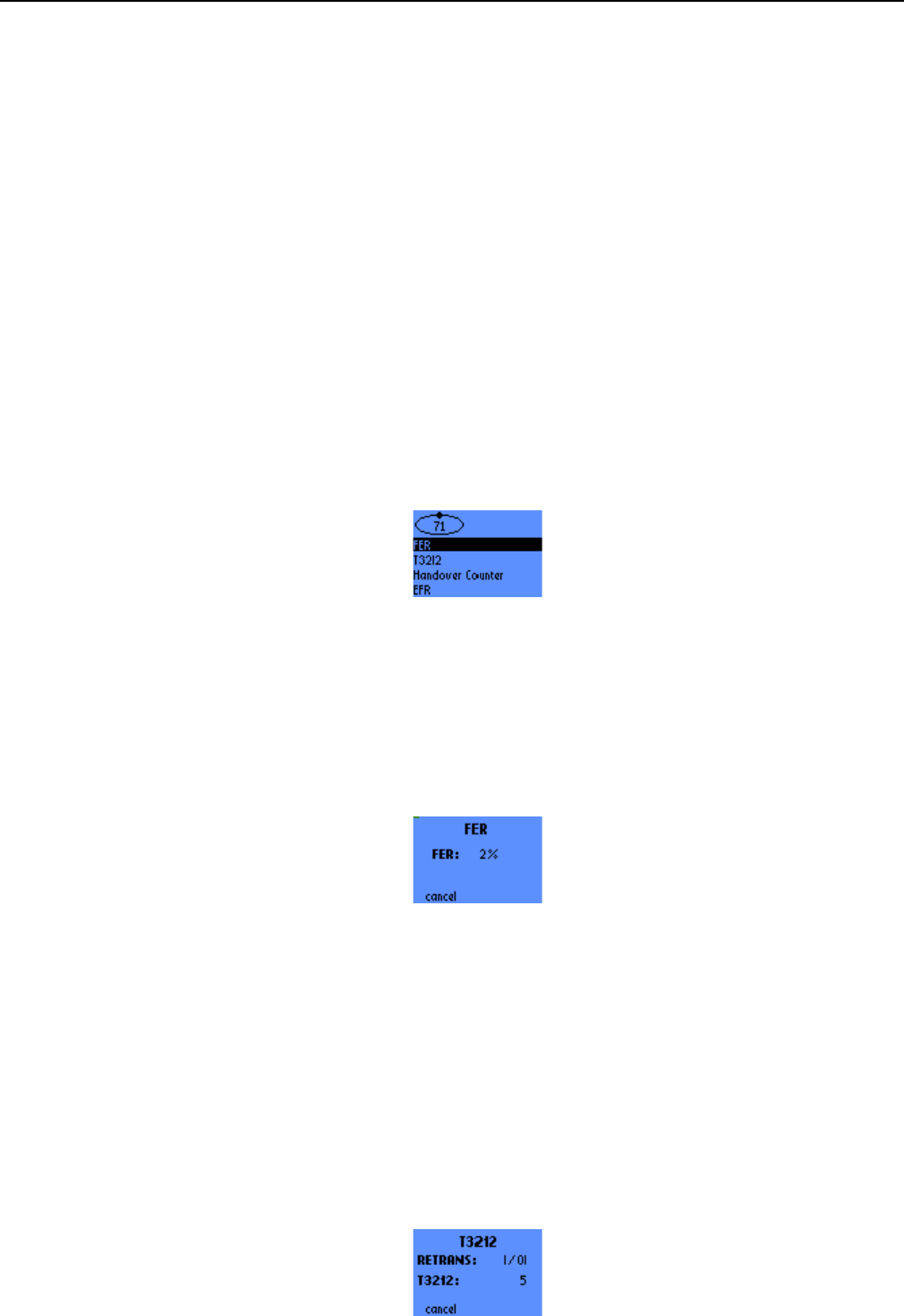
2.9.1 FER full....................................................................................................................................... 45
2.9.2 T3212 ......................................................................................................................................... 45
2.9.3 Handover Counter...................................................................................................................... 46
2.9.4 EFR ............................................................................................................................................ 46
2.10 SERIAL LINK SETUP ................................................................................................................... 46
2.11 RF SCANNING in progress screen............................................................................................. 47
3. SWITCHING BETWEEN WAP BROWSER AND TRACE SCREENS .....................48

s
ERef. : SCT TMO LOG SPEC 163
Revision : B
Sec. Ref. :
Date : 2003-01-22
E. CONFIDENTIAL All rights of reproduction and disclosure reserved. Page 5 / 52
3.1 Escaping from the WAP browser................................................................................................... 48
3.1.1 Escaping the WAP browser – general procedure ...................................................................... 48
3.1.2 Escaping the WAP browser during a voice call ......................................................................... 48
3.2 Starting WAP transfer from the Trace Menu screens.................................................................. 48
3.2.1 Switching to the WAP browser................................................................................................... 48
3.2.2 Starting the homepage connection ............................................................................................ 48
3.2.3 Starting a bookmark connection................................................................................................. 49
4. ANNEX: GPRS QOS PARAMETERS DEFINITION.................................................50
4.1 Data Transfer 2nd Screen (LLC) parameters.................................................................................. 50
4.1.1 Retransmitted LLC Frame Rate ................................................................................................. 50
4.1.2 LLC Data throughput.................................................................................................................. 50
4.1.3 Total LLC frames transmitted..................................................................................................... 51
4.2 Data Transfer 3rd Screen (RLC) parameters.................................................................................. 51
4.2.1 Retransmitted RLC Block Rate .................................................................................................. 51
4.2.2 RLC/MAC Data throughput traces .............................................................................................51
4.2.3 Total RLC blocks transmitted..................................................................................................... 52
4.3 Measurement Info parameter ......................................................................................................... 52

s
ERef. : SCT TMO LOG SPEC 163
Revision : B
Sec. Ref. :
Date : 2003-01-22
E. CONFIDENTIAL All rights of reproduction and disclosure reserved. Page 6 / 52
1. OBJECT
1.1 INTRODUCTION.
The purpose of this document is to define the MMI (Machine-Man Interface) Trace specification for the OT
product line, some feature depends on the mobile .
For each category of the trace menu, this document describes, with graphical examples, the possible
choices that are offered to the user, along with the keypad controls used to browse through the successive
screens, to enter parameters and to modify the settings. The available categories are as follow:
• MS Info: gives information related to the Mobile Station,
• Network Info: displays various parameters concerning the serving and neighbouring cells,
• GPRS Info
(only available with OT supporting GPRS ): displays parameters related to packet data
service,
• SIM Info: allows to monitor or modify information stored in the SIM,
• Forcing Functions: these functions allow to manually modify the behavior of the mobile and of the
network,
• BCCH Scanning: performs RF power measurements on the whole band and searches for BCCH
channels,
• QoS Info: displays parameters related to the provided Quality of Service,
• Serial Link Setup: sets up the serial link parameters.
Please note that the screens presented in this document are not contractual.
1.2 REFERENCE ELEMENTS
[03.64] : Serial link trace interface specification for trace mobile M42 (OT M42 STB 004E)
[03.64] : Digital cellular telecommunications system (Phase 2+) ; General Packet Radio Service (GPRS) ; Overall
Description of the GPRS radio interface ; Stage 2 (Release 1997)
[04.04] : Digital cellular telecommunications system (Phase 2+) ; Layer 1 ; General requirements (Release 1997)
[04.07] : Digital cellular telecommunications system (Phase 2+) ; Mobile radio interface signalling layer 3 ;
General aspects (Release 1997)
[04.08] : Digital cellular telecommunications system (Phase 2+) ; Mobile radio interface layer 3 specification
(Release 1997)

s
ERef. : SCT TMO LOG SPEC 163
Revision : B
Sec. Ref. :
Date : 2003-01-22
E. CONFIDENTIAL All rights of reproduction and disclosure reserved. Page 7 / 52
[04.60] : Digital cellular telecommunications system (Phase 2+) ; General Packet Radio Service (GPRS) ; Mobile
Station (MS) - Base Station System (BSS) interface ; Radio Link Control/ Medium Access Control (RLC\MAC)
protocol (Release 1997)
[04.64] : Digital cellular telecommunications system (Phase 2+) ; General Packet Radio Service (GPRS) ; Mobile
Station (MS) - Serving GPRS Support Node (SGSN) - Logical Link Control (LLC) layer specification (Release
1997)
[04.65] : Digital cellular telecommunications system (Phase 2+); General Packet Radio Service (GPRS);
Subnetwork Dependent Convergence Protocol (SNDCP).
[04.65] : Digital cellular telecommunications system (Phase 2+); Multiplexing and multiple access on the radio
path
[04.65] : Digital cellular telecommunications system (Phase 2+); Radio transmission and reception (Release
1997)
[04.65] : Digital cellular telecommunications system (Phase 2+); Radio subsystem link control (Release 1997)
[04.64] : Digital cellular telecommunications system (Phase 2+); General Packet Radio Service (GPRS); Mobile
Station (MS) supporting GPRS (Release 1997)
[04.64] : Digital cellular telecommunications system (Phase 2+); Specification of the Subscriber Identity Module -
Mobile Equipment (SIM - ME) interface
s
ERef. : SCT TMO LOG SPEC 163
Revision : B
Sec. Ref. :
Date : 2003-01-22
E. CONFIDENTIAL All rights of reproduction and disclosure reserved. Page 8 / 52
2. TRACE FUNCTIONS
2.1 TRACE MENU
The trace menu MINFO is accessible with Menu # (scroll push-buttons: ∧
∧∧
∧ or ∨
∨∨
∨ and #)
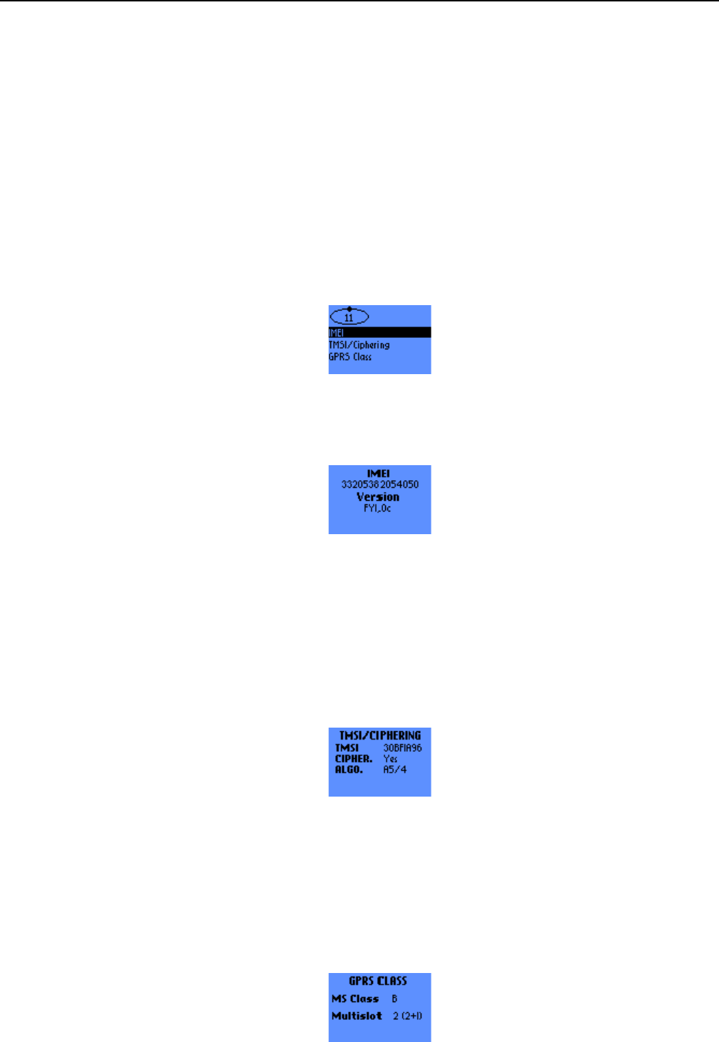
Up to 8 choices are available in this menu :
• 1 MS Info
• 2 Network
• 3 GPRS Info)
• 4 SIM Info
• 5 Forcing Functions
• 6 BCCH Scanning
• 7 QoS Info
• 8 Serial Link Setup
To browse through the successive menus, press the scroll push-buttons: ^ Next menu and v Previous
menu.
2.2 UPDATE OF THE TRACED INFORMATION
The traced information are updated in real time at each event by the RHM, for example at the incoming of
PSI or SI. There is also no need of polling from the RHM to the MS.
s
ERef. : SCT TMO LOG SPEC 163
Revision : B
Sec. Ref. :
Date : 2003-01-22
E. CONFIDENTIAL All rights of reproduction and disclosure reserved. Page 9 / 52
2.3 MS INFO
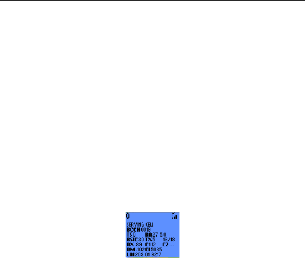
This menu contains 3 entries:
• IMEI
• TMSI/Ciphering
• GPRS Class The scroll push-buttons ^ and v are used to browse through the menu.
2.3.1 IMEI
This sub-menu gives the IMEI of the mobile and the software version.
2.3.2 TMSI/GSM Ciphering
This sub-menu gives the following information:
• TMSI: 4 bytes displayed in hexadecimal
• GSM Ciphering activated: Yes or No
• GSM Ciphering algorithm: A5/1, A5/2, A5/3, A5/4, A5/5, A5/6 or A5/7, as defined in [04.08].
2.3.3 GPRS Class
This sub-menu gives the following information:
• MS Class: gives the Mobile Station GPRS Class (B or C)
• Multislot: MS class for multislot capability, as defined in [05.02]. Between parenthesis is indicated the
number of timeslots in the Downlink and in the Uplink.
s
ERef. : SCT TMO LOG SPEC 163
Revision : B
Sec. Ref. :
Date : 2003-01-22
E. CONFIDENTIAL All rights of reproduction and disclosure reserved. Page 10 / 52
2.4 NETWORK
This function is used to display the values of the main parameters received from the serving cell and six
neighbouring cells, in standby mode (IDLE) as well as in dedicated mode .
You can dial while in the trace screens by keying the digits of the remote number followed by the ✆
✆✆
✆ key.
After starting the call, the mobile display will automatically return to trace screen. You can also call the last
number dialed by pressing the ✆
✆✆
✆ key.
Data are displayed in 2 screens for each cell, i.e. up to 14 successives screens.
To browse through the successives screens, press the scroll push-buttons: ^ Next screen and v Previous
screen.
From these screens, you can display additional screens by pressing the Ok key.
When the reception conditions prevent decoding of some information received from the network, the
values of the corresponding parameters are replaced by “-“.
2.4.1 SERVING CELL Main screen in IDLE mode
This screen displays synthetically the values of the main parameters received from the network, concerning the
serving cell:
- BCCH :
Current ARFCN of the BCCH (channel number).
- TS : 0 to 7
Current TIME SLOT number (TS is 0 in idle mode).
- BA : nm x.y
Number of elements in the BA list.
nm 1 to 32
CCCH configuration on BCCH and PCH:
x2
to 9
Current value of BS_PA_MFRMS
y 0, 1, 2, 4 or 6
Current value of CCH_CONF
- BSIC : ab
Current value of the BSIC (Base Station Identity Code) for the serving cell:
a0
to 7
Digit corresponding to the operator code (NCC).
b0
to 7
Digit corresponding to the cell colour code (BCC).
- TX : Current value of MS_TXPWR_MAX_CCH for the serving cell.
s
ERef. : SCT TMO LOG SPEC 163
Revision : B
Sec. Ref. :
Date : 2003-01-22
E. CONFIDENTIAL All rights of reproduction and disclosure reserved. Page 11 / 52
- cd/mdDownlink signalling counter indicator with :
cd : current downlink signalling counter
md : maximum downlink signalling counter
- RX : -110 to -11 dBm
Current value of RX_LEV_SERVING_CELL for the BCCH of the serving cell.
- C1 : -92 to 127
Current value of the criterion C1 for the serving cell.
- C2 : -92 to 127
Current value of the cell reselection criterion C2 for the serving cell if the
network allows to calculate it.
- RM : -110 to -46 dBm
Current value of RX_LEV_ACCES_MIN for the serving cell in dBm.
- CI : abcde
Current value of the CI (Cell Identity) on 4 hexadecimal digits.
- LAI : abc de fghij
Current value of the Location Area Identity:
abc Country code on 3 digits (MCC).
de Operator code on 2 digits (MNC).
fghij Location area code on 5 decimal digits (LAC).
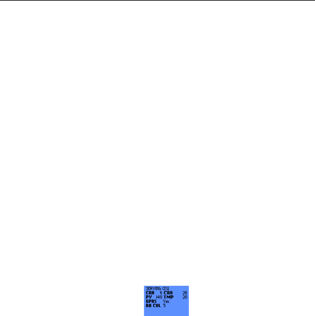
2.4.2 SERVING CELL Second screen in IDLE mode
This screen gives additional GSM Cell Reselection information along with information about the GPRS
capability of the Serving Cell:
- CRH: 0 to 14 dB, 2 dB steps
Current value of CELL RESELECT HYSTERESIS for the Serving cell
- CRO: 0 to 126 dB, 2 dB steps
Current value of CELL RESELECT OFFSET for the Serving cell
- PY: 20 to 620 s, 20 s steps. None if no Temporary Offset is used
Current value of PENALTY TIME for the Serving Cell.
- TMP: 0 to 60 dB, 10 dB steps. Inf for Infinite Temporary Offset
Current value of TEMPORARY OFFSET for the Serving Cell
- GPRS: Yes or No
Indicates whether the Serving Cell supports GPRS or not
- RA COL: 0 to 7
Current value of RA Colour for the Serving Cell (only valid if the Serving Cell supports GPRS)

s
ERef. : SCT TMO LOG SPEC 163
Revision : B
Sec. Ref. :
Date : 2003-01-22
E. CONFIDENTIAL All rights of reproduction and disclosure reserved. Page 12 / 52
2.4.3 NEIGHBOURING CELL Main screen in IDLE mode
The six following screens of the NETWORK function give the values of the main parameters received from the
BCCH of the six neighbouring cells.
The information concerning a neighbouring cell is displayed on one screen :
- NEIGHBOURING CELL 1 to 6
Current order number of the cell in the list of neighbours.
- BCCH :
BCCH ARFCN (channel number) of the neighbouring cell.
- FN : +abcdefg
Frame offset between the neighbouring cell and the serving cell.
- BSIC : ab
Current value of the BSIC (Base Station Identity Code) for the neighbouring cell:
a0
to 7
Digit corresponding to the Network Colour Code (NCC).
b0
to 7
Digit corresponding to the Base Colour Code (BCC).
- TX : Current value of MS_TXPWR_MAX_CCH for the neighbouring cell.
- RX : -110 to -11 dBm
Current value of RX_LEV_NCELL for the BCCH of the neighbouring cell in dBm.
- RM : -110 to -46 dBm
Current value of RX_LEV_ACCESS_MIN for the neighbouring cell in dBm.
- C1 : -92 to 127
Current value of the criterion C1 for the neighbouring cell.
- C2 : -92 to 127
Current value of the cell reselection criterion C2 for the neighbouring cell if the network allows to
calculate it.
- RM : -110 to -46 dBm
Current value of RX_LEV_ACCESS_MIN for the neighbouring cell in dBm.
- QBO: +hijk
Quarter Bit Offset: finer complementary offset expressed in number of quarter bit between the
neighbouring cell and the serving cell.
s
ERef. : SCT TMO LOG SPEC 163
Revision : B
Sec. Ref. :
Date : 2003-01-22
E. CONFIDENTIAL All rights of reproduction and disclosure reserved. Page 13 / 52
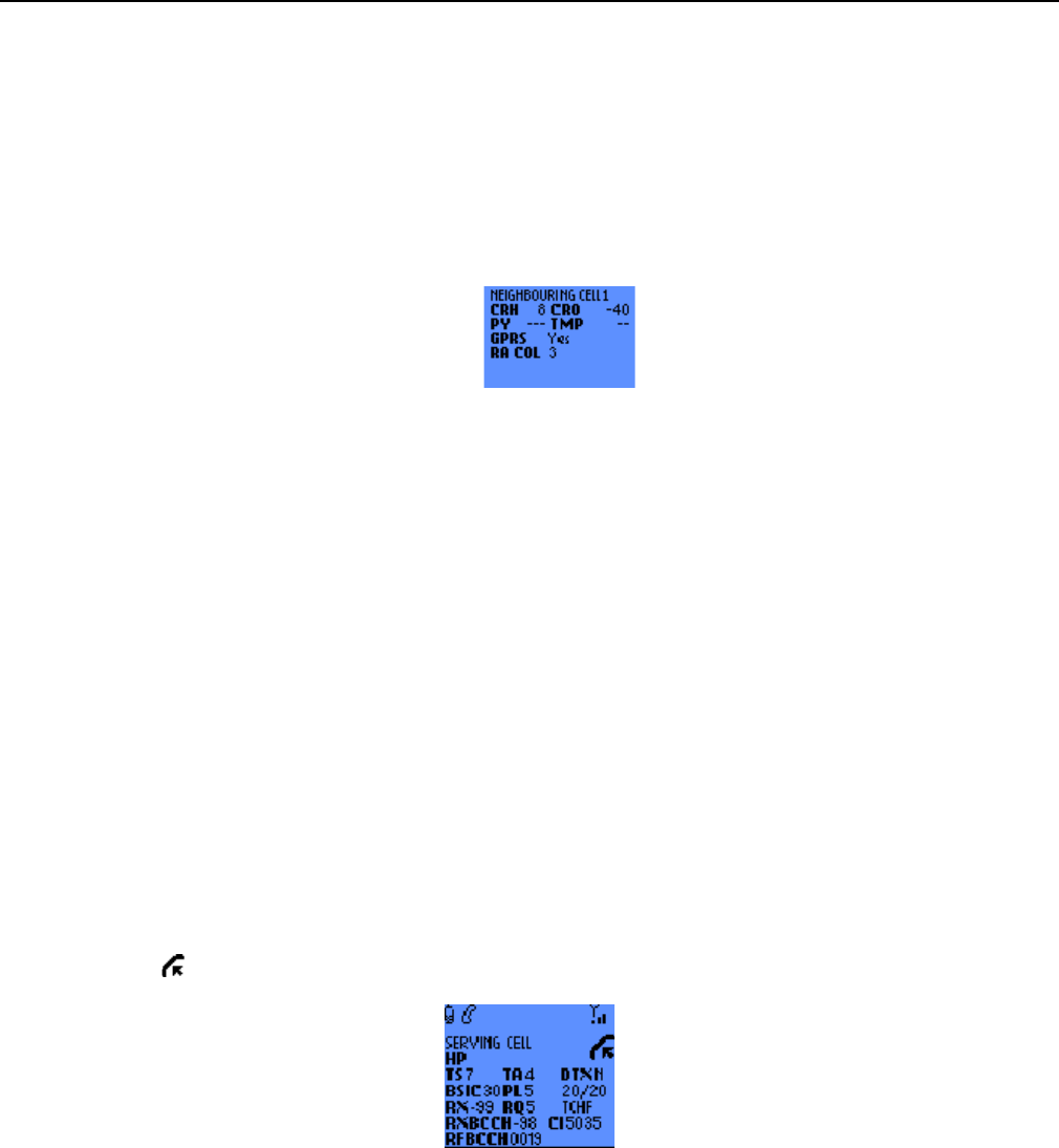
2.4.4 NEIGHBOURING CELL Second screen in IDLE mode
This screen gives additional GSM Cell Reselection information along with information about the GPRS
capability of the Neighbouring Cell:
- CRH: 0 to 14 dB, 2 dB steps
Current value of CELL RESELECT HYSTERESIS for the Neighbouring cell
- CRO: 0 to 126 dB, 2 dB steps
Current value of CELL RESELECT OFFSET for the Neighbouring cell
- PY: 20 to 620 s, 20 s steps. None if no Temporary Offset is used
Current value of PENALTY TIME for the Neighbouring Cell
- TMP: 0 to 60 dB, 10 dB steps. Inf for Infinite Temporary Offset
Current value of TEMPORARY OFFSET for the Neighbouring Cell
- GPRS: Yes or No
Indicates whether the Neighbouring Cell supports GPRS or not
- RA COL: 0 to 7
Current value of RA Colour for the Neighbouring Cell. Only valid if the Neighbouring Cell supports
GPRS
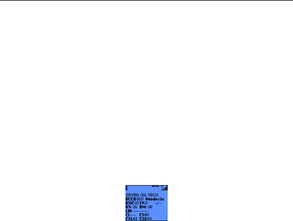
2.4.5 SERVING CELL screen in DEDICATED mode
This screen supplies synthetically the values of the main parameters received from the network, concerning the
serving cell. The icon indicates that the mobile is in dedicated mode.
- TCH : cha or HP
Current TCH ARFCN (Traffic channel number). When the network uses FREQUENCY
HOPPING, the channel number is replaced by the indication HP.
- TS : 0 to 7
Current TIME SLOT number.
- TA : 0 to 63
Current value of the TIMING ADVANCE expressed in number of bit times.
To convert the displayed value into µs, simply multiply it by 3.69.
- DTX : Y or N
The DTX (Discontinuous Transmission) mode is used for uplink Yes (Y) or no (N).
- BSIC : ab

s
ERef. : SCT TMO LOG SPEC 163
Revision : B
Sec. Ref. :
Date : 2003-01-22
E. CONFIDENTIAL All rights of reproduction and disclosure reserved. Page 14 / 52
Current value of the BSIC (Base Station Identity Code) for the serving cell:
a0
to 7
Digit corresponding to the Network Colour Code (NCC).
b0
to 7
Digit corresponding to the Base Colour Code (BCC).
- PL : Current value of the POWER_LEVEL.
- cr/mr Radio link timeout indicator :
cr : current radio link timeout
mr : maximum radio link timeout.
- RX : -110 to -11 dBm
Current value of RX_LEV_SERVING_CELL for the TCH of the serving cell in dBm.
- RQ : 0 to 7
Current value of the RX_QUAL.
- SD/TCType of current channel.
When establishing the call, SDCCH/8 or 4 is displayed for a short time to indicate that the current
channel is the SDCCH/8 or 4. Then is displayed e TCHF or TCHH depending on the coding rate
(FR or HR).
- RXBCCH : -110 to -11
Current value of RX_LEV_SERVING_CELL for the BCCH of the serving cell during a call in dBm.
- CI : abcde
Current value of the CI (Cell Identity) on 5 decimal digits.
- RFBCCH :
BCCH ARFCN (channel number) used for the current cell.
2.4.6 NEIGHBOURING CELL screen in DEDICATED mode
The six following screens of the NETWORK function give the values of the main parameters on measurement
reports.
The information concerning a neighbouring cell is displayed on the following screen. The icon indicates that
the mobile is in dedicated mode.
- NEIGHBOURING CELL 1 to 6
Current order number of the cell in the list of neighbours.
- CH : 1 to 124
RF BCCH channel number (CHANNEL) of the neighbouring cell.
s
ERef. : SCT TMO LOG SPEC 163
Revision : B
Sec. Ref. :
Date : 2003-01-22
E. CONFIDENTIAL All rights of reproduction and disclosure reserved. Page 15 / 52
- FN : +abcdefg
Frame offset between the neighbouring cell and the serving cell.
- BSIC : ab
Current value of the BSIC (Base Station Identity Code) for the neighbouring cell:
a0
to 7
Digit corresponding to the operator code.
b0
to 7
Digit corresponding to the cell colour code.
- QBO: +hijk
Quarter Bit Offset : finer complementary offset expressed in number of quarter bit between the
neighbouring cell and the serving cell.
- RX : -110 to -11 dBm
Current value of RX_LEV_NCELL for the BCCH of the neighbouring cell in dBm.
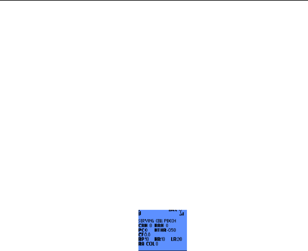
2.4.7 SERVING CELL Main screen in PBCCH mode
This screen displays synthetically the values of the main parameters received from the network, concerning the
serving cell:
- BCCH :
BCCH channel number..
- MODE : Trans or Idle
'Trans' if the MS transfers data through the GPRS. Else Idle mode
- BSIC : ab
Current value of the BSIC (Base Station Identity Code) for the serving cell:
a0
to 7
Digit corresponding to the Network Color Code.
b0
to 7
Digit corresponding to the Base Color code.
- TX : Current value of GPRS_MS_TXPWR_MAX_CCH for the serving cell.
- cd/mdDownlink signalling counter indicator with :
cd : current downlink signalling counter
md : maximum downlink signalling counter
- RX : -110 to -11 dBm
Current value of RX_LEV_SERVING_CELL for the PBCCH of the serving cell.
- RM : -110 to -46 dBm
Current value of GPRS_RX_LEV_ACCES_MIN for the serving cell in dBm.
- LAI : abc de fghij
Current value of the Location Area Identity:
s
ERef. : SCT TMO LOG SPEC 163
Revision : B
Sec. Ref. :
Date : 2003-01-22
E. CONFIDENTIAL All rights of reproduction and disclosure reserved. Page 16 / 52
abc Mobile Country Code on 3 digits (MCC).
de Mobile Network Code on 2 digits (NCC).
fghij Location Area Code on 5 decimal digits (LAC).
- CI : abcde
Current value of the CI (Cell Identity) on 4 hexadecimal digits.
- C1 : -92 to 127
Current value of the criterion C1 for the serving cell.
- C31 : -Current value of the criterion C31 for the serving cell.
- C32 : -Current value of the criterion C32 for the serving cell.
2.4.8 SERVING CELL Second screen in PBCCH mode
This screen gives additional GSM Cell Reselection information along with information about the GPRS
capability of the Serving Cell:
- CRH: 0 to 14 dB, 2 dB steps
Current value of GPRS CELL RESELECT HYSTERESIS for the Serving cell
- RRH: 0 to 14 dB, 2 dB steps.
Current value of GPRS RA RESELECT HYSTERESIS for the Serving Cell
- PC: 0 to 7
Current value of Priority Class for the Serving Cell
- HTHR: -110dB to -48dB, 2dB steps
Current value of HCS THR (signal level threshold) for the Serving Cell
- CF: x.y
x: 0 or 1.
Current value of the C31_HYST flag of the Serving Cell.
y: 0 or 1.
Current value of C32_QUAL flag of the Serving Cell.
- RP: 1 to 16
Current value of PSI1 Repeat period for the Serving Cell
- HR: 1 to 16
Current value of PSI High Rate for the Serving Cell
- LR: 0 to 63
Current value of PSI Low Rate for the Serving Cell
s
ERef. : SCT TMO LOG SPEC 163
Revision : B
Sec. Ref. :
Date : 2003-01-22
E. CONFIDENTIAL All rights of reproduction and disclosure reserved. Page 17 / 52
- RA COL: 0 to 7
Current value of RA Color for the serving Cell. Only valid if the Cell supports GPRS.
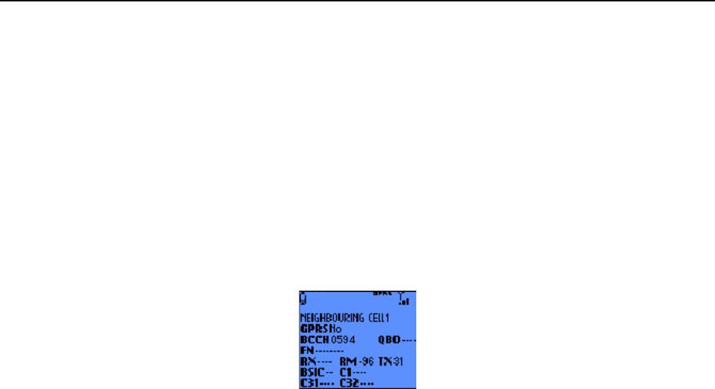
2.4.9 NEIGHBOURING CELL first screen in PBCCH mode
The following screens of the NETWORK function give the values of parameters received from the PBCCH of the
six neighbours cells.
The information concerning a neighbour cell is displayed on two screens :
•
First screen description:
- NEIGHBOURING CELL 1 to 6
Current order number of the cell in the list of neighbours.
- GPRS:
"n=No": No GPRS Information "BCCH": GPRS but no PBCCH detected
"GPRS PBCCH": GPRS with a PBCCH.
- PBCCH :
BCCH (channel number) of the cell.
- QBO: +hijk
Quarter Bit Offset: finer complementary offset expressed in number of quarter bit between the
neighbouring cell and the serving cell.
- FN : +abcdefg
Frame offset between the neighbouring cell and the serving cell.
- RX : -110 to -11 dBm
Current value of RX_LEV_NCELL for the BCCH or PBCCH of the cell in dBm.
- RM : -110 to -46 dBm
Current value of GPRS_RX_LEV_ACCESS_MIN for the cell in dBm, if the cell has a PBCCH.
Else current value of RX_LEV_ACCESS_MIN.
- TX : Current value of GPRS_MS_TXPWR_MAX_CCH for the neighbouring cell, if the cell has a
PBCCH. Else current value of MS_TXPWR_MAX_CCH.
- BSIC : ab
Current value of the BSIC (Base Station Identity Code) for the neighbouring cell:
a0
to 7
Digit corresponding to the Mobile Coutry Code (MCC).
b0
to 7
Digit corresponding to the Mobile Network Code (MNC).
- C1 : -92 to 127
Current value of the criterion C1 for the cell.
s
ERef. : SCT TMO LOG SPEC 163
Revision : B
Sec. Ref. :
Date : 2003-01-22
E. CONFIDENTIAL All rights of reproduction and disclosure reserved. Page 18 / 52
- C31 : -Current value of the criterion C31 for the cell.
- C32 : -Current value of the criterion C32 for the cell.
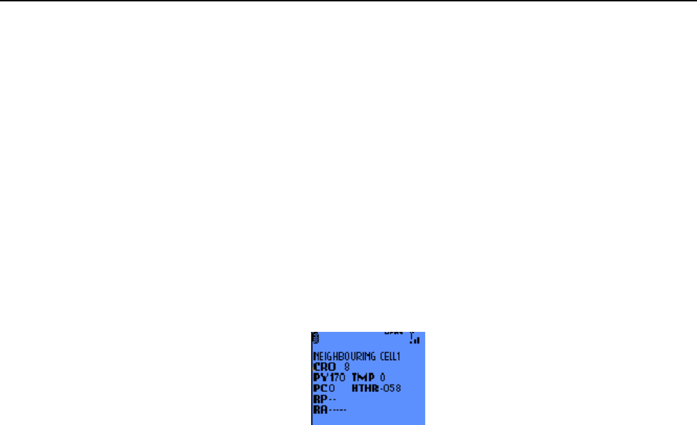
2.4.10 NEIGHBOURING CELL Second screen in PBCCH mode
This screen gives additional GSM Cell Reselection information along with information about the GPRS
capability of the Neighbouring Cell:
- CRO: 52 to +48 dB, 2 dB steps between -12 to +12 dB, and 4 dB step between -52 and -12dB and
between +12 and +48 dB.0.
Current value of GPRS RESELECT OFFSET for the Neighbouring cell
- PY: 20 to 620 s, 20 s steps. None if no Temporary Offset is used
Current value of PENALTY TIME for the Neighbouring Cell
- TMP: 0 to 60 dB, 10 dB steps. Inf for Infinite Temporary Offset
Current value of TEMPORARY OFFSET for the Neighbouring Cell
- PC: 0 to 7
Current value of Priority Class for the Serving Cell.
- HTHR: -110dB to -48dB, 2dB steps
Current value of HCS THR (signal level threshold) for the cell.
- RP: 1 to 16
Current value of PSI1 Repeat period for the cell
- RA: "serving" or "other"
serving: if the Routing Area of the neighbouring cell is the same as the Serving Cell.
s
ERef. : SCT TMO LOG SPEC 163
Revision : B
Sec. Ref. :
Date : 2003-01-22
E. CONFIDENTIAL All rights of reproduction and disclosure reserved. Page 19 / 52
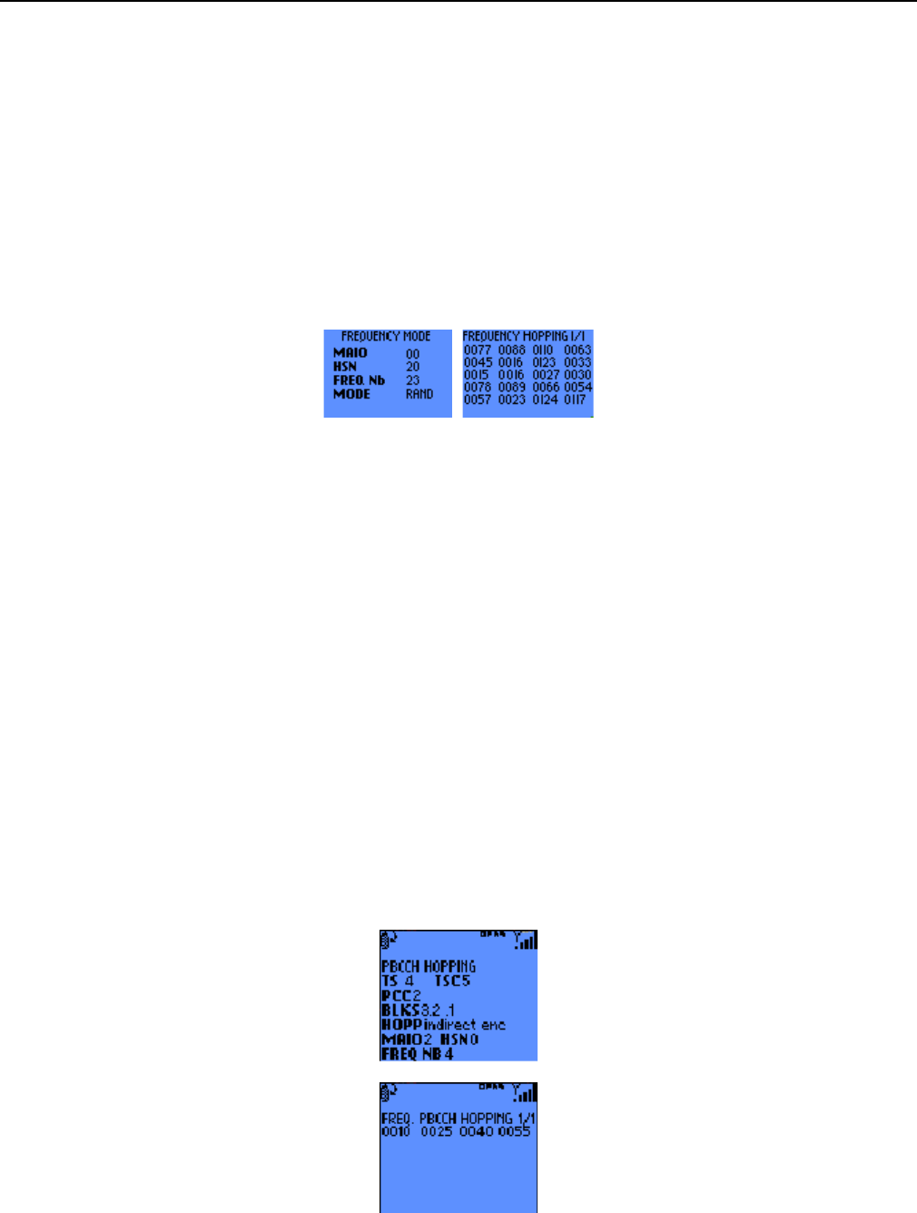
2.4.11 TCH Hopping features in Dedicated mode
It is the 8th screen in dedicated mode. I There may be up to 3 additional screens for the hopping frequencies.
These screens give the values of certain additional parameters concerning frequency hopping in the cell and the
list of the hopping frequencies if any. When there are more than 24 hopping frequencies, pressing the Ok key
allows to display the next 24 hopping frequencies. If there are more than 48 frequencies, pressing a second time
the Ok key allows to display the last hopping frequencies.
- MAIO: 0 to 63Mobile allocation index offset.
- HSN: 0 to 63 Hopping sequence number of the dedicated channel.
- FREQ_NB: 0 to 1023
number of hopping frequencies for dedicated channel.
- MODE: Random or Cyclic
Type of the frequency hopping of the dedicated channel.
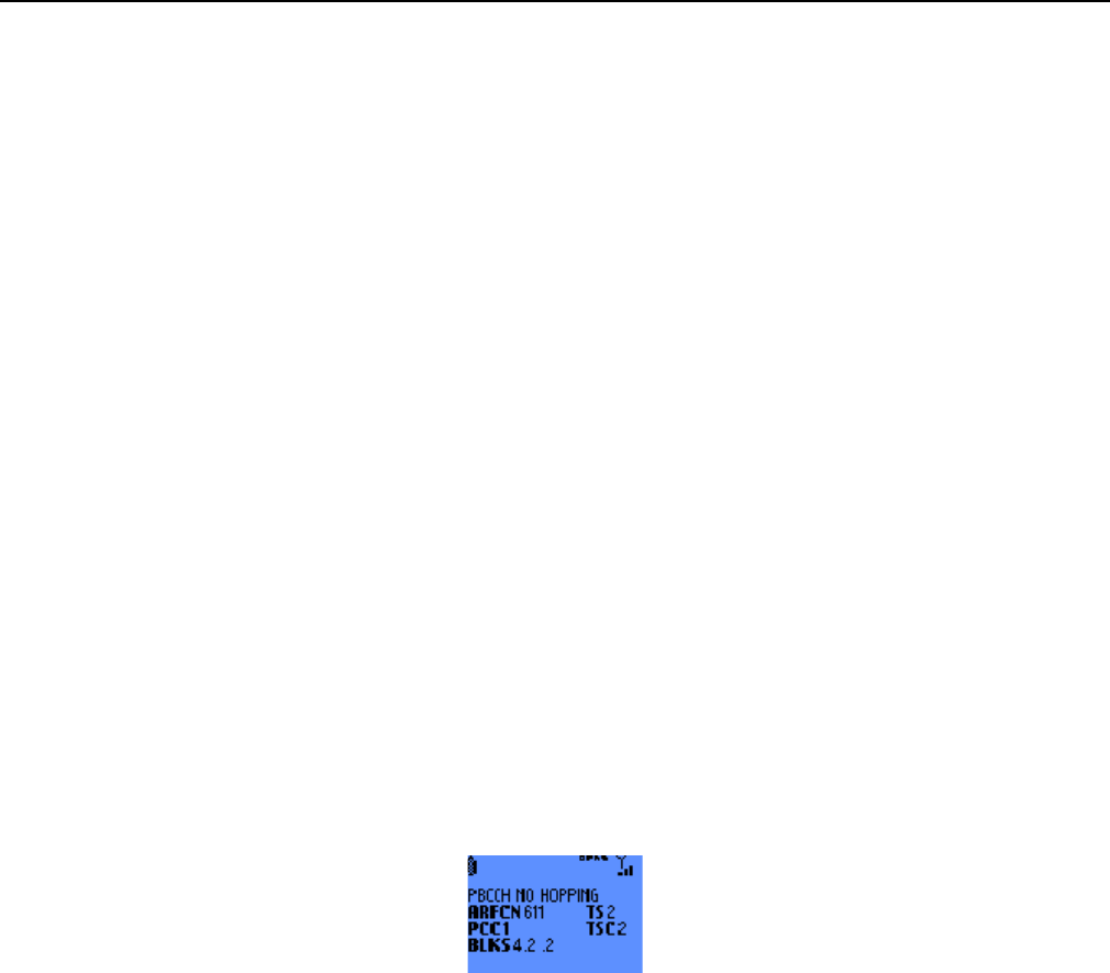
2.4.12 PBCCH frequency screens in PBCCH mode with hopping
The first screen is the 15th screen and the other(s) are just after. There may be up to 3 additional screens for the
hopping frequencies.
These screens give the values of parameters concerning frequency and the list of the hopping frequencies. When
there are more than 24 hopping frequencies, pressing the Ok key allows to display the next 24 hopping
frequencies. If there are more than 48 frequencies, pressing a second time the Ok key allows to display the last
hopping frequencies.
- TS : 0 to 7 TS of the PBCCH.
- TSC: 0 to 7 Training sequence code.
s
ERef. : SCT TMO LOG SPEC 163
Revision : B
Sec. Ref. :
Date : 2003-01-22
E. CONFIDENTIAL All rights of reproduction and disclosure reserved. Page 20 / 52
- PCC: 0 to 7 Current value of the BS_PCC_CHANS, the number of PCCCH description blocks occurrences.
- BS BLKS: x.y.z
x: 1 to 4
Current value of BS PBCCH BLKS for the Serving Cell
y: 0 to 12
Current value of BS PAG BLKS RES for the Serving Cell
z: 0 to 12
Current value of BS PRACH BLKS for the Serving Cell
- HOPP: "direct enc 1", "direct enc 2" or "indirect enc".
Type of the frequency hopping.
- MAIO: 0 to 63Mobile allocation index offset.
- HSN: 0 to 63 Hopping sequence number.
- FREQ_NB: 0 to 1023 Number of hopping frequencies for the PBCCH channel.
2.4.13 PBCCH frequency screens without hopping
It is the 15th in the PBCCH mode, when the PBCCH has no hopping frequencies. This screen gives the values of
certain additional parameters concerning the PBCCH.
- ARFCN: 0 to 1023
Absolute Radio Frequency channel number of the PBCCH .
- TS : 0 to 7 TS of the PBCCH.
- PCC: 0 to 7 Current value of the BS_PCC_CHANS, the number of PCCCH description block occurrence.
- TSC: 0 to 7 Training sequence code.
- BS BLKS: x.y.z
x: 1 to 4
Current value of BS PBCCH BLKS for the Serving Cell
y: 0 to 12
Current value of BS PAG BLKS RES for the Serving Cell
z: 0 to 12
Current value of BS PRACH BLKS for the Serving Cell
s
ERef. : SCT TMO LOG SPEC 163
Revision : B
Sec. Ref. :
Date : 2003-01-22
E. CONFIDENTIAL All rights of reproduction and disclosure reserved. Page 21 / 52
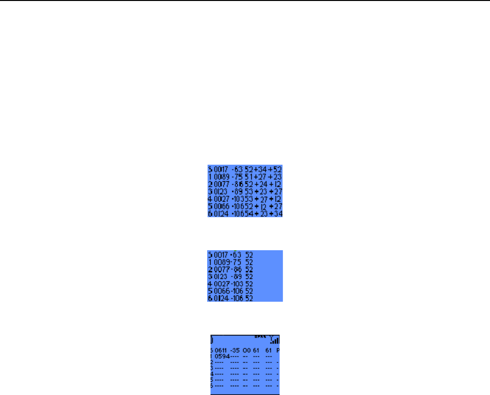
2.4.14 Network summary screen
Pressing the Ok key from one of the previous screens displays a network summary screen pressing the C key
returns to the previous screen.
The first line contains information about the serving cell. The next six lines give information about the six
neighbouring cells.
If the mobile is in Idle mode. The information provided is BCCH, Rx level, BSIC, C1 and C2 :
If the mobile is in Dedicated mode. The information provided are BCCH, Rx level and BSIC :
If the mobile is in packet idle mode. The information provided is BCCH, Rx level, BSIC, C1, C32 and GPRS
information:
The GPRS information on the cell are coded on 1 character:
• P: GPRS with PBCCH.
• G: GPRS without PBCCH.
• ' ' : GSM (No GPRS).
2.5 GPRS INFO
This menu gives access to GPRS-related parameters. It contains 7 entries:
• Mobility Info
• PDP Context
• Data Transfer Info
• Ciphering Info
• Measurement Info
• Paging Info
• Packet Bursts Info

s
ERef. : SCT TMO LOG SPEC 163
Revision : B
Sec. Ref. :
Date : 2003-01-22
E. CONFIDENTIAL All rights of reproduction and disclosure reserved. Page 22 / 52
The scroll push-buttons ^ and v are used to browse through the menu.

s
ERef. : SCT TMO LOG SPEC 163
Revision : B
Sec. Ref. :
Date : 2003-01-22
E. CONFIDENTIAL All rights of reproduction and disclosure reserved. Page 23 / 52
2.5.1 Mobility Info
This screen gives information related to mobility:
• Atch: Attach State
! N: not GPRS-attached
! I: GPRS-attached while IMSI attached
! C: combined-attached
! G: GPRS only attached
!
• GMM: GMM Service State
! SB: Stand-By
! I: Idle
! R: Ready
• PTMSI: Packet Temporary Mobile Station Identifier. Coded on 4 bytes, displayed in hexadecimal
• TLLI: Temporary Link Level Identifier. Coded on 4 bytes, displayed in hexadecimal
• RAC: Routing Area Code. Coded on 1 byte, displayed in hexadecimal
• NC: Network Control Order
! NC0: MS controlled cell re-selection, no measurement reporting
! NC1: MS controlled cell re-selection, MS sends measurement reports
! NC2: Network controlled cell re-selection, MS sends measurement reports
• T3314: value of the GMM READY timer. 0 to 11160 s
s
ERef. : SCT TMO LOG SPEC 163
Revision : B
Sec. Ref. :
Date : 2003-01-22
E. CONFIDENTIAL All rights of reproduction and disclosure reserved. Page 24 / 52
2.5.2 PDP Context
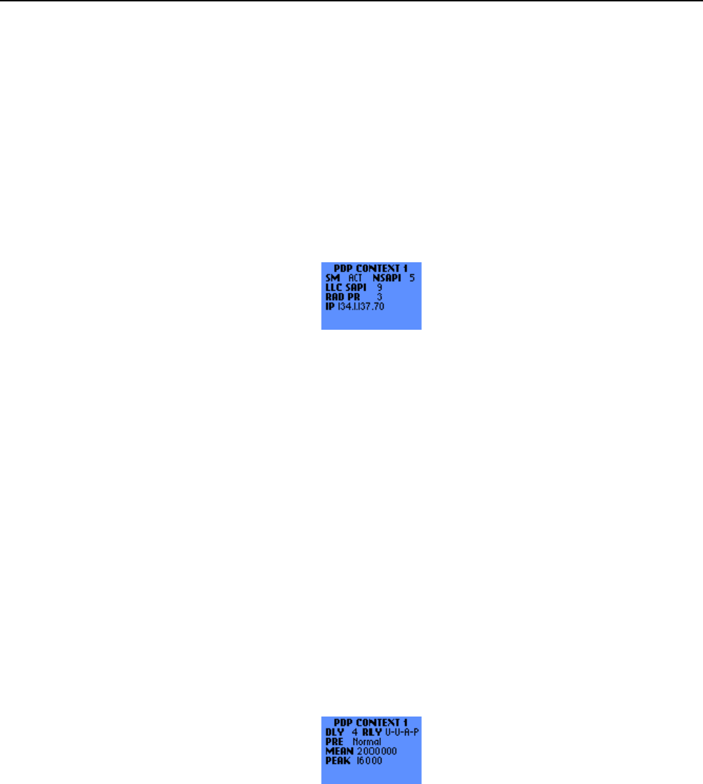
These screen give information about the parameters that are negotiated between the network and the
mobile station at PDP Context activation. The scroll push-buttons ^ and v are used to browse through the
successive screens. The total number of screens depends on the maximum allowed number of concurrent
PDP Context. There are 2 screens for each PDP context.
2.5.2.1 PDP Context 1st screen
• SM: SM Service State for the PDP Context. If SM = INA or ACP, all the other parameters of both
screen are invalid for this PDP Context (except for the NSAPI parameter which is also valid when in
Active Pending SM state)
! INA: Inactive
! ACP: Active Pending
! INP: Inactive Pending
! ACT: Active
• NSAPI: Network Service Access Point Identifier for the PDP Context. 5 to 15
• LLC SAPI: LLC Service Access Point Identifier for the PDP Context. 3, 5, 9 or 11
• RAD PR: Radio Priority for the PDP Context. Ranges from 1 (highest priority) to 4 (lowest priority)
• IP: IP address associated to the PDP Context. 4 bytes displayed in decimal
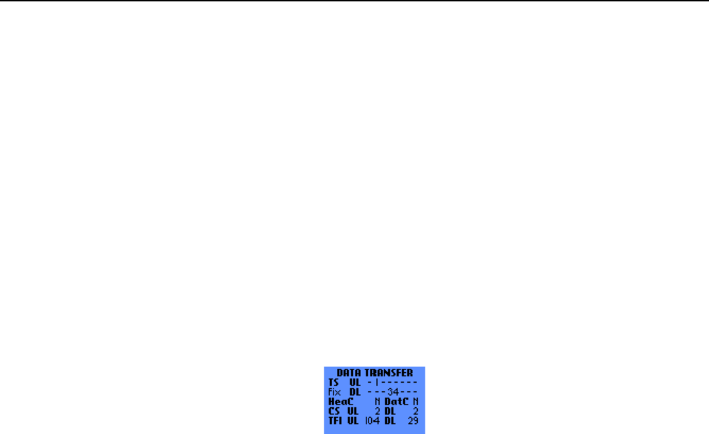
2.5.2.2 PDP Context 2nd screen
• DLY: Delay Class. Ranges from 1 to 4 (best effort)
• RLY g-l-r-p: Reliability Class
! g: GTP mode (A: Acknowledged, U: Unacknowledged)
! l: LLC mode (A: Acknowledged, U: Unacknowledged)
! r: RLC mode (A: Acknowledged, U: Unacknowledged)
! p: data protection (P: Protected Data, U: Unprotected Data)
• PRE: Precedence Class
s
ERef. : SCT TMO LOG SPEC 163
Revision : B
Sec. Ref. :
Date : 2003-01-22
E. CONFIDENTIAL All rights of reproduction and disclosure reserved. Page 25 / 52
! High: High priority
! Normal: Normal priority
! Low: Low priority
• MEAN: granted mean throughput. 100 to 50 000 000 bytes/hour
• PEAK: peak throughput. 1000 to 256 000 bytes/s
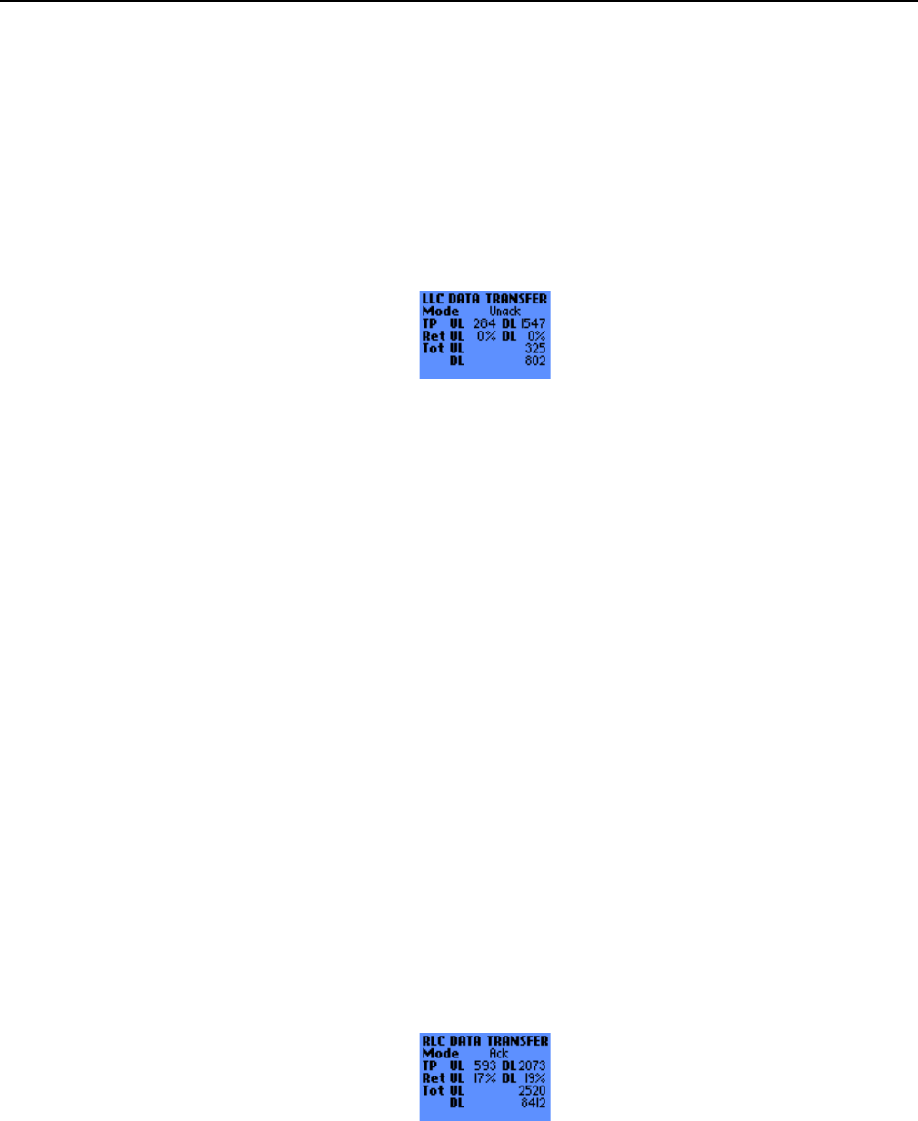
2.5.3 Data Transfer Info
These screen give information about the current data transfer.
2.5.3.1 Data Transfer 1st Screen
• TS: below the TS label is displayed the Timeslot Allocation Type:
! Dyn: Dynamic allocation
! Fix: Fixed allocation
! No: No allocation
• on the right side of the TS label are displayed the Uplink and Downlink timeslot allocation
! UL: Uplink Timeslot allocation. A dash (“-“) indicates an unallocated timeslot, a digit indicates an
allocated timeslot (and also indicates its timeslot number)
! DL: Downlink Timeslot allocation. A dash (“-“) indicates an unallocated timeslot, a digit indicates an
allocated timeslot (and also indicates its timeslot number)
• HeaC: SNDCP Header Compression
! Y: SNDCP Header Compression used
! N: SNDCP Header Compression not used
• DatC: SNDCP Data Compression
! Y: SNDCP Data Compression used
! N: SNDCP Data Compression not used
• CS: Coding Scheme. 1 to 4
! UL: Uplink Coding Scheme
! DL: Downlink Coding Scheme
• TFI: Temporary Flow Identifier. Coded on 7 bits, displayed in decimal
s
ERef. : SCT TMO LOG SPEC 163
Revision : B
Sec. Ref. :
Date : 2003-01-22
E. CONFIDENTIAL All rights of reproduction and disclosure reserved. Page 26 / 52
! UL: Uplink Temporary Flow Identifier
! DL: Downlink Temporary Flow Identifier
2.5.3.2 Data Transfer 2nd Screen (LLC)
This screen displays informationabout data transfer at the LLC layer:
• Mode: LLC transfer mode
! Ack: Acknowledged
! Unack: Unacknowledged
• TP: LLC throughput, in byte/s (see 4.1.2 for more details)
! UL: Uplink LLC throughput
! DL: Downlink LLC throughput
• Ret: LLC retransmitted frame rate, in percentage (only in Acknowledged LLC mode, see 4.1.1 for
more details)
! UL: Uplink LLC retransmitted frame rate
! DL: Downlink LLC retransmitted frame rate
• Tot: total LLC frames transmitted (see 4.1.3 for more details)
! UL: total Uplink LLC frames transmitted
! DL: total Downlink LLC frames transmitted
2.5.3.3 Data Transfer 3rd Screen (RLC)
This screen displays informationabout data transfer at the RLC layer:
• Mode: RLC transfer mode
! Ack: Acknowledged
! Unack: Unacknowledged
• TP: RLC throughput, in byte/s (see 4.2.2 for more details)
! UL: Uplink RLC throughput
s
ERef. : SCT TMO LOG SPEC 163
Revision : B
Sec. Ref. :
Date : 2003-01-22
E. CONFIDENTIAL All rights of reproduction and disclosure reserved. Page 27 / 52
! DL: Downlink RLC throughput
• Ret: RLC retransmitted block rate, in percentage (only in Acknowledged RLC mode, see 4.2.1 for
more details)
! UL: Uplink RLC retransmitted block rate
! DL: Downlink RLC retransmitted block rate
• Tot: total RLC blocks transmitted (see 4.2.3 for more details)
! UL: total Uplink RLC blocks transmitted
! DL: total Downlink RLC blocks transmitted
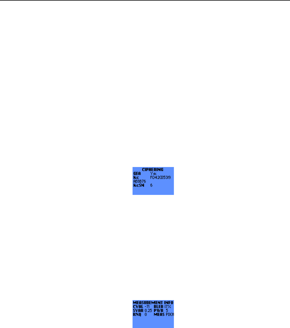
2.5.4 Ciphering Info
This screen displays parameters related to GPRS ciphering:
• GEA: indicates whether the GPRS Encryption Algorithm 1 is used or not
! 1: GPRS Encryption Algorithm 1 used
! No: no GPRS Encryption Algorithm used
• Kc: Ciphering Key. Coded on 8 bytes, displayed in hexadecimal
• KcSN: Ciphering Key Sequence Number. Coded on 3 bits, displayed in decimal
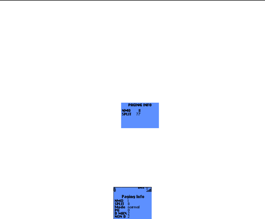
2.5.5 Measurement Info
This screen gives information about parameters measured by the MS:
• CVAL: C_VALUE parameter. in dBm
• SVAR: SIGN_VAR parameter. 0 to 15.75 dB², by steps of 0.25 dB²
• RXQ: RXQUAL. Coded from 0 to 7, as specified in [05.08]
• BLER: Block Error Rate. This parameter indicates the Block Error Rate of the radio connection. in
percentage (see 4.3 for more details)
• PWR: MS Output Power. This parameter is encoded as specified in [05.05]
s
ERef. : SCT TMO LOG SPEC 163
Revision : B
Sec. Ref. :
Date : 2003-01-22
E. CONFIDENTIAL All rights of reproduction and disclosure reserved. Page 28 / 52
• MEAS: PC_MEAS_CHAN. Indicates the type of channel that shall be used for downlink measurements
for power control. This parameter can take 2 values:
! BCCH: the measurements shall be performed on the BCCH
! PDCH: the measurements shall be performed on the PDCH
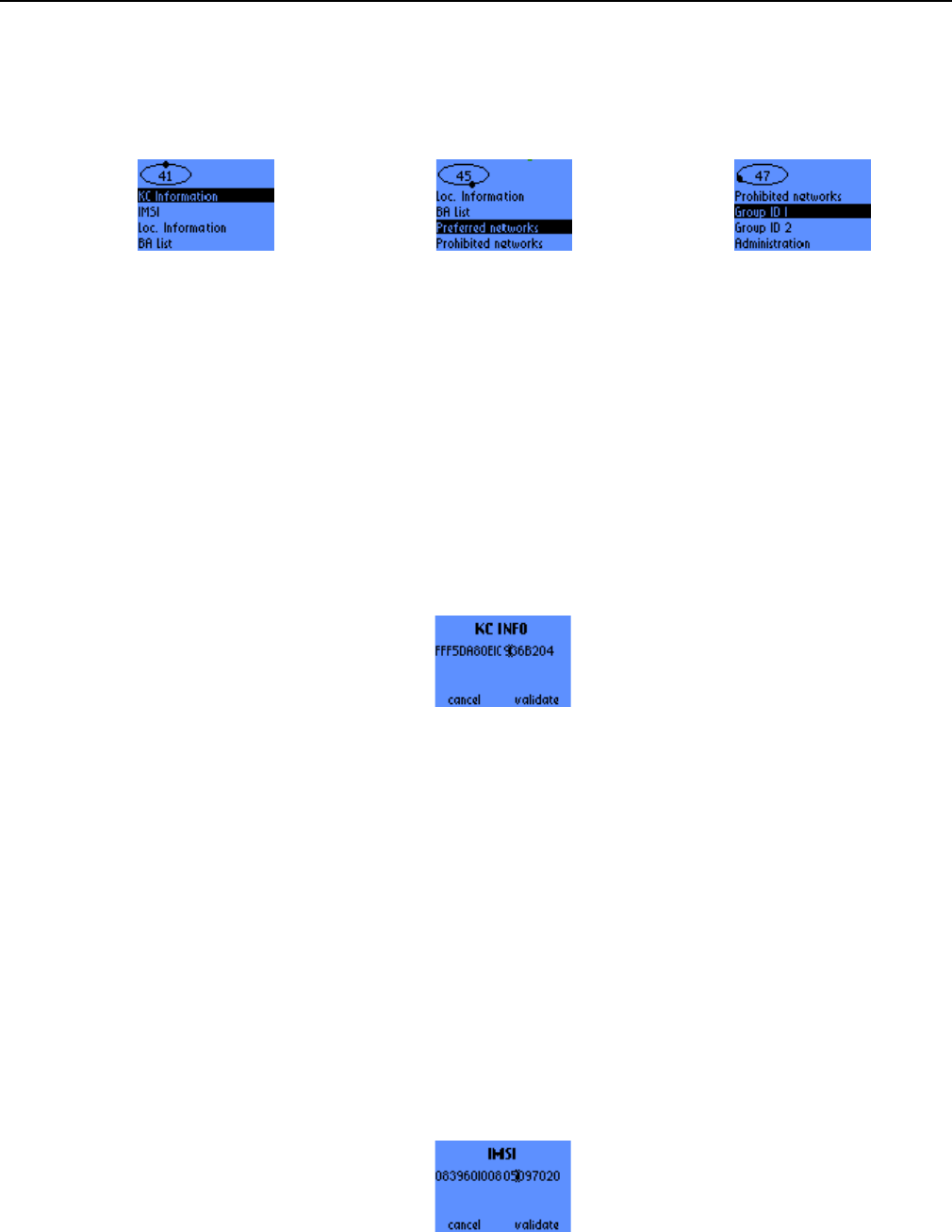
2.5.6 Paging Info without PBCCH
This screen gives information about how paging shall be performed:
• NMO: Network Mode of Operation (I, II or III)
• SPLIT: SPLIT_PG_CYCLE. Ranges from 0 to 352
2.5.7 Paging Info with PBCCH
This screen gives information about how paging shall be performed:
• NMO: Network Mode of Operation (I, II or III)
• SPLIT: SPLIT_PG_CYCLE. Ranges from 0 to 352
• MODE: "Normal", "Extended", "reorganisation", "same".
• PG: 0 to 1023
Current value of the Paging group for the MS.
• D MAX: 0, 1, 2, 4, 8, 16 ,32 and 64s
Current value of the DRX_TIMER_MAX of the cell.
• NON D: 0, 1, 2, 4, 8, 16 ,32 and 64s
Current value of the NON_DRX_TIMER negotiated by the MS.

s
ERef. : SCT TMO LOG SPEC 163
Revision : B
Sec. Ref. :
Date : 2003-01-22
E. CONFIDENTIAL All rights of reproduction and disclosure reserved. Page 29 / 52
2.5.8 Packet Bursts Info
This screen displays parameters about the format of packet bursts :
• CTRL: CONTROL_ACK_TYPE parameter. It can take the following values:
! 4 ACC: the default format for PACKET CONTROL ACKNOWLEDGMENT messages is 4 access
bursts
! RLC/MAC: the default format for PACKET CONTROL ACKNOWLEDGMENT messages is an
RLC/MAC Control Block
• ACC: ACCESS_BURST_TYPE parameter. 11 or 8 bits
• PRIO: PRIORITY_ACCESS_THR parameter. It can take the following values:
! N: packet access not allowed in the cell
! 1: packet access allowed for priority level 1
! 1-2: packet access allowed for priority levels 1 and 2
! 1-3: packet access allowed for priority levels 1 to 3
! 1-4: packet access allowed for priority levels 1 to 4
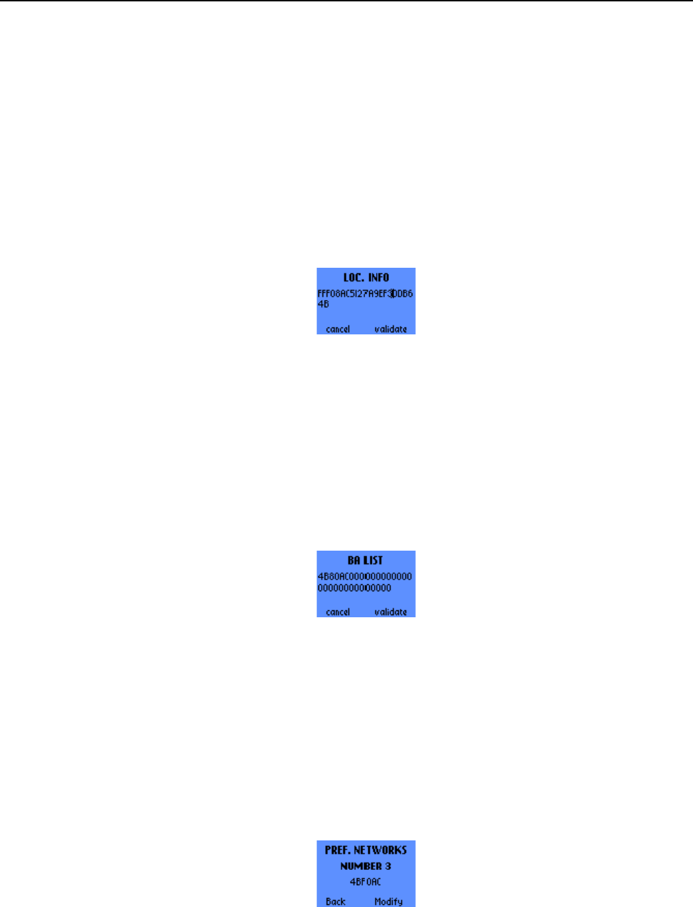
2.6 SIM INFO
This menu gives access to information that is stored on the SIM. It contains the following entries:
• KC information
• IMSI
• Loc. information
• BA List
• Preferred Networks
• Prohibited Networks
• Group ID 1
• Group ID 2
• Administration
s
ERef. : SCT TMO LOG SPEC 163
Revision : B
Sec. Ref. :
Date : 2003-01-22
E. CONFIDENTIAL All rights of reproduction and disclosure reserved. Page 30 / 52
Use the scroll push-buttons ^ and v to browse through this menu.
2.6.1 KC Information
This screen allows to modify the KC key and the KC key sequence number. This parameters are displayed
in hexadecimal form and in the same format as they are stored in the SIM (see [11.11] for more details):
• The 2 rightmost digits represent the 8-bit long KC key sequence number. The actual KC key sequence
number is encoded using the 3 Least Significant Bits.
• The 16 other digits represent the 64-bit long KC key
The C button and the ^ button move the cursor to the left, the v button moves the cursor to the right.
The OK (or the right one-touch button) validates the changes, while the left one-touch button (or the C
button if the cursor has reached the left side of the screen) cancels the changes.
2.6.2 IMSI
This screen allows to see the IMSI. This parameter is displayed in decimal form and in the same format as
it is stored in the SIM (see [11.11] for more details):
• The 2 leftmost digits indicate the length (in bytes) of the IMSI.
• The third digit from the left is the 1st digit of the IMSI
• The fourth digit from the left is related to the parity bit (see [11.11]). It should normally be equal to 1 or
9.
• The remaining digit are the other digit of the IMSI, but they must be inverted two by two (fifth digit from
the left on the screen = 3nd digit of the IMSI, sixth digit from the left on the screen = 2nd digit of the
IMSI, last digit on the screen = 14th digit of the IMSI)
The C button and the ^ button move the cursor to the left, the v button moves the cursor to the right.
s
ERef. : SCT TMO LOG SPEC 163
Revision : B
Sec. Ref. :
Date : 2003-01-22
E. CONFIDENTIAL All rights of reproduction and disclosure reserved. Page 31 / 52
2.6.3 Loc. Information
This screen allows to modify the Location Information. This 11-byte long parameter is displayed in
hexadecimal form.
The C button and the ^ button move the cursor to the left, the v button moves the cursor to the right.
The OK (or the right one-touch button) validates the changes, while the left one-touch button (or the C
button if the cursor has reached the left side of the screen) cancels the changes.
2.6.4 BA List
This screen allows to modify the BA List. This parameter is 11-byte long and is displayed in hexadecimal
form. Each bit corresponds to a frequency.
The C button and the ^ button move the cursor to the left, the v button moves the cursor to the right.
The OK (or the right one-touch button) validates the changes, while the left one-touch button (or the C
button if the cursor has reached the left side of the screen) cancels the changes.
2.6.5 Preferred Networks
2.6.5.1 Display screens
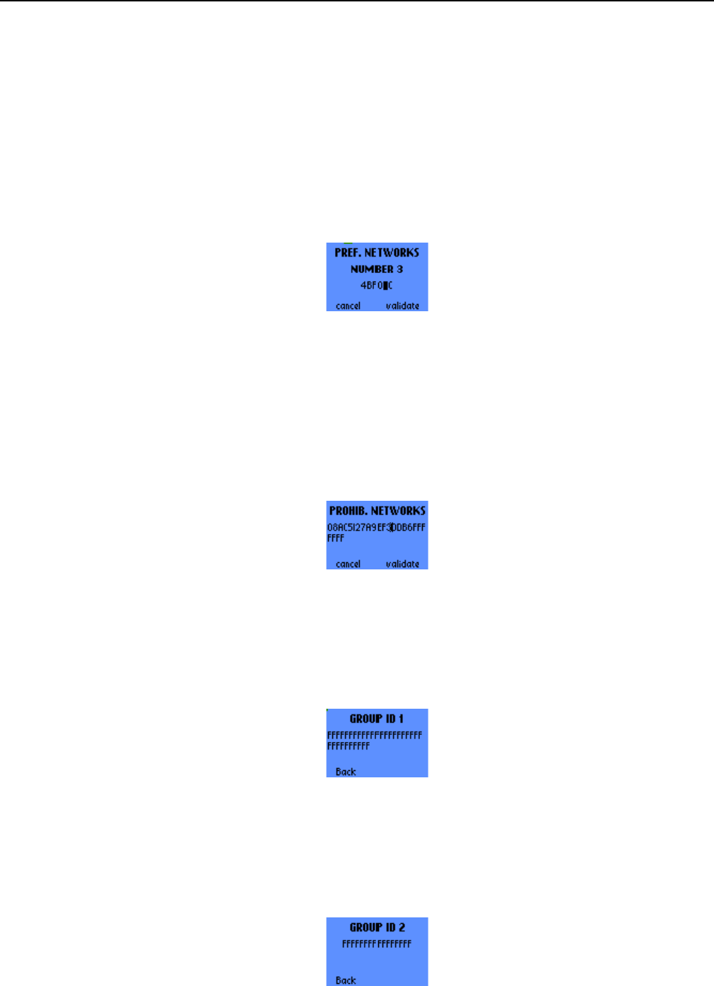
These screens display the preferred networks (up to 32 entries). Each entry is 3-bytes long and is
displayed in hexadecimal form.
To browse through the different preferred networks, use the scroll push-buttons ^ and v.
The C button (or the left one-touch button) returns to the SIM menu. The OK button (or the right one-touch
button) allows to enter the modification screen.
s
ERef. : SCT TMO LOG SPEC 163
Revision : B
Sec. Ref. :
Date : 2003-01-22
E. CONFIDENTIAL All rights of reproduction and disclosure reserved. Page 32 / 52
2.6.5.2 Modification screen
This screen allows to modify a network from the preferred network list. The C button and the ^ button move
the cursor to the left, the v button moves the cursor to the right.
The left one-touch button cancels the modification and returns to the previous screen. The OK button and
the right one-touch button validates the modification.
2.6.6 Prohibited Networks
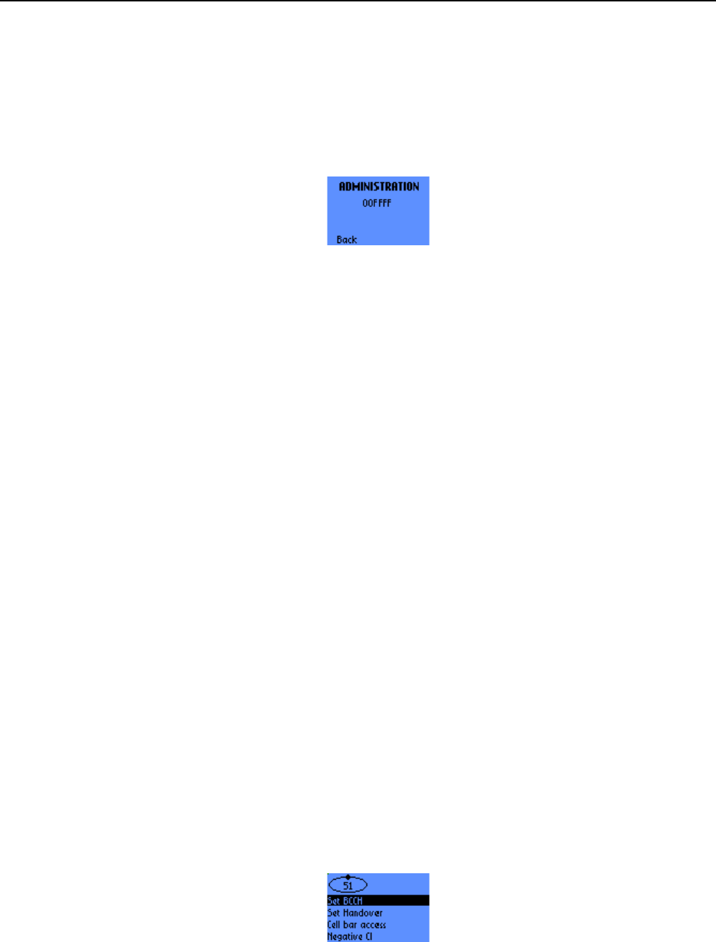
This screen allows to modify the Prohibited Network list. This parameter is 12-byte long and is displayed in
hexadecimal form. Each byte corresponds to a network.
The C button and the ^ button move the cursor to the left, the v button moves the cursor to the right.
The OK (or the right one-touch button) validates the changes, while the left one-touch button (or the C
button if the cursor has reached the left side of the screen) cancels the changes.
2.6.7 Group ID 1
This screen displays the Group ID Level 1, that can be used to identify a group of SIMs for a particular
application. This parameter has a length of 16 bytes and is displayed in hexadecimal form.
The C button (or the left one-touch button) returns to the SIM scroll menu.
2.6.8 Group ID 2
This screen displays the Group ID Level 2, that can be used to identify a group of SIMs for a particular
application. This parameter has a length of 8 bytes and is displayed in hexadecimal form.
The C button (or the left one-touch button) returns to the SIM scroll menu.
s
ERef. : SCT TMO LOG SPEC 163
Revision : B
Sec. Ref. :
Date : 2003-01-22
E. CONFIDENTIAL All rights of reproduction and disclosure reserved. Page 33 / 52
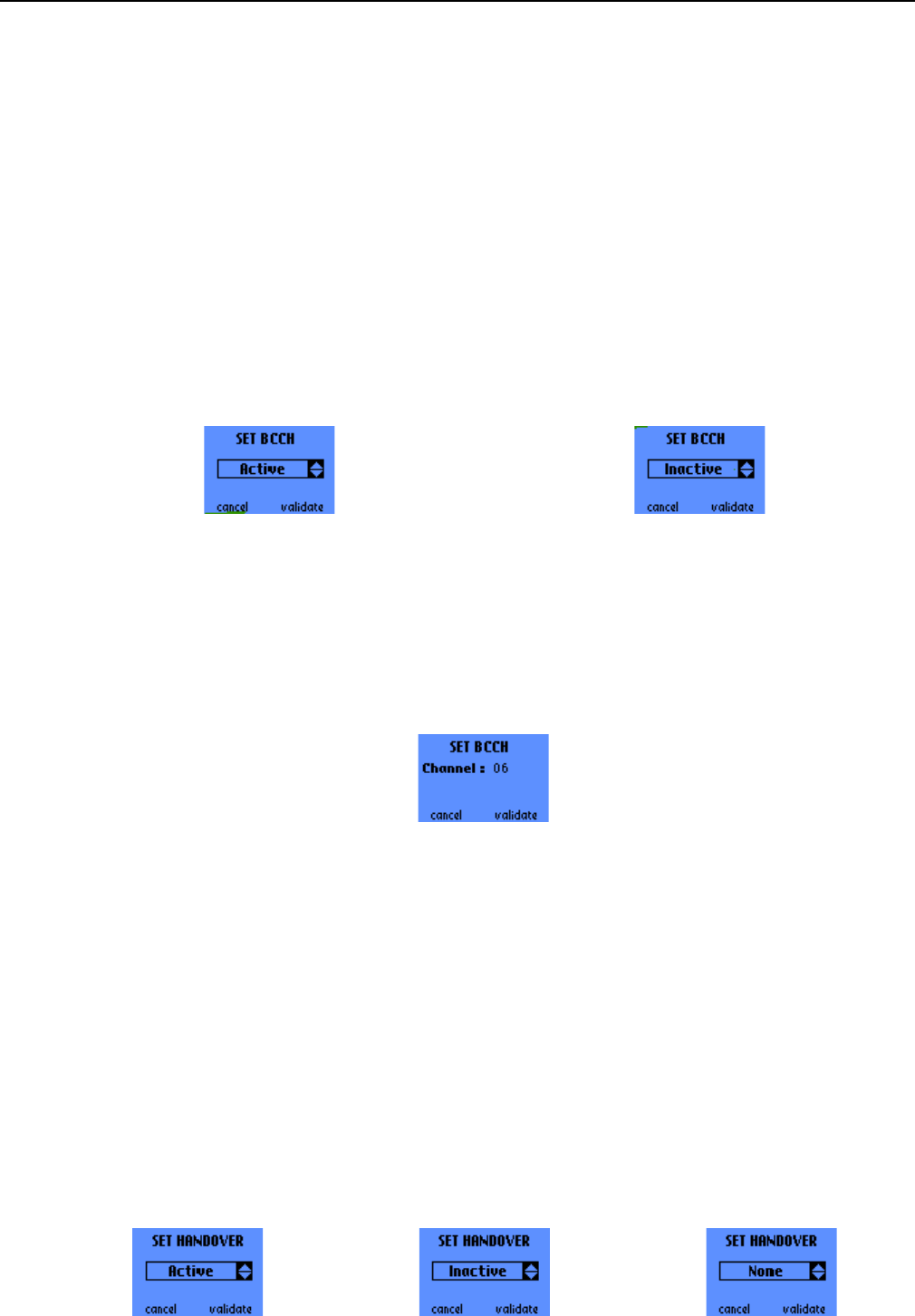
2.6.9 Administration
This screen indicates whether the SIM card is a test SIM or not. It displays a 3-byte parameter in
hexadecimal form.
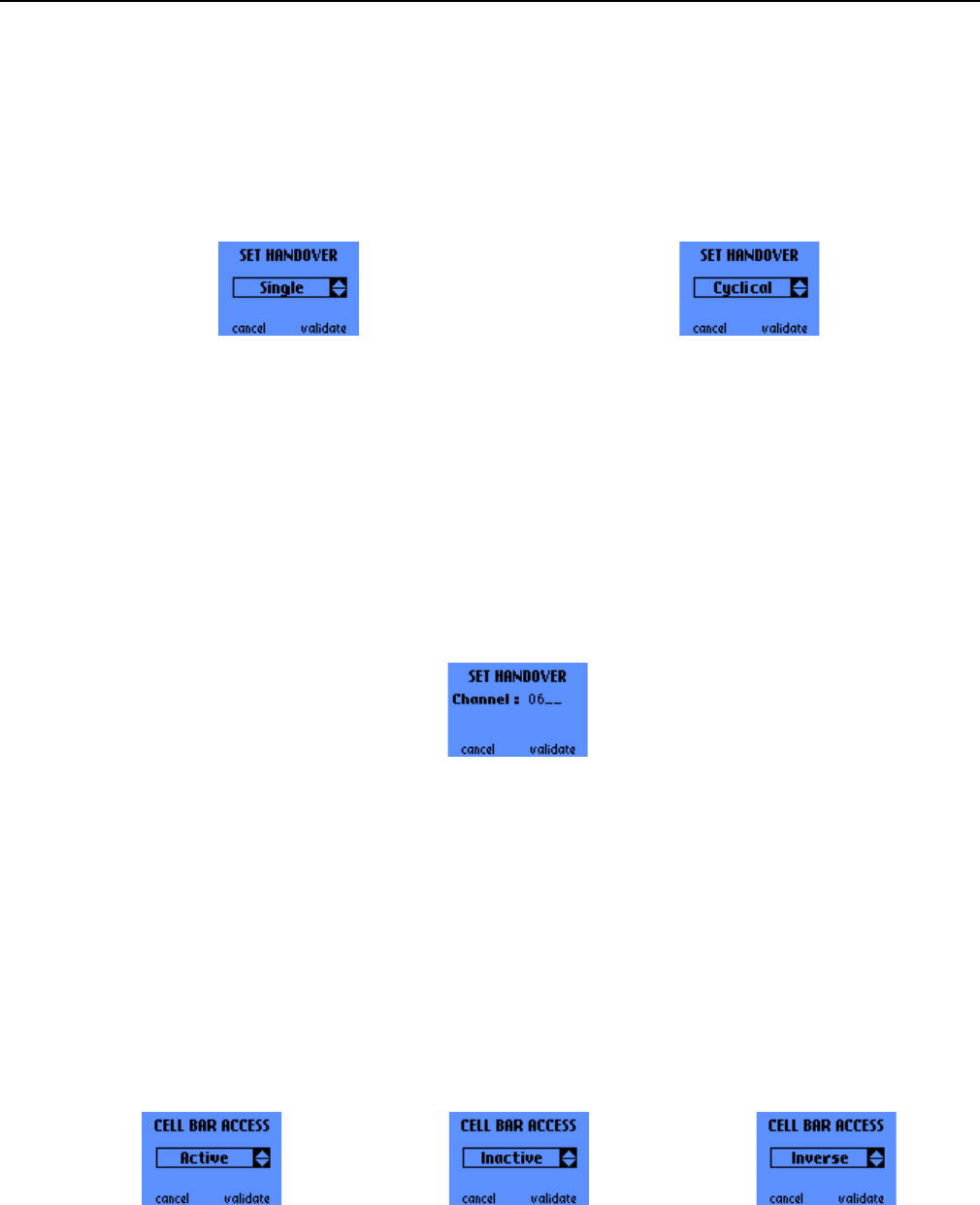
2.7 FORCING FUNCTIONS
This menu contains up to 14 entries:
• Set BCCH
• Set Handover
• Cell Bar Access
• Negative C1
• Set Power Class
• RF Measurement
• Set Full Rate
• Set Band
• Set Cell Reselection
• Set GPRS Coding Scheme
• Set GPRS Auto Attach)
• Set GPRS Multislot Class
• Set GPRS Class
• Summary
The scroll push-buttons ^ and v are used to browse through the menu.
s
ERef. : SCT TMO LOG SPEC 163
Revision : B
Sec. Ref. :
Date : 2003-01-22
E. CONFIDENTIAL All rights of reproduction and disclosure reserved. Page 34 / 52
2.7.1 Set BCCH
NOTE: the BCCH forcing function and the RF MEASUREMENT, RF SCANNING and BCCH SCANNING
functions are mutually exclusive. If this forcing function is active when switching to RF MEASUREMENT,
RF SCANNING or BCCH SCANNING mode, it will be automatically deactivated.
2.7.1.1 Activation/Deactivation screen
This screen is used to activate or deactivate the Set BCCH forcing function. To choose between “Active”
and “Inactive” use the scroll push-buttons ^ and v.
The OK button (or the right one-touch button) validates the choice, while the C button (or the left one-touch
button) cancels and returns to the Forcing Functions general scrolling menu.
NOTE: this forcing function can only be activated or deactivated in GSM IDLE mode.
2.7.1.2 BCCH channel prompt
If the “Active” choice is validated, a second screen prompts for the BCCH frequency number on which the
mobile shall attempt to camp. The C button deletes the previously entered digit, or cancel the operation if
no digit is present, while the left one-touch button cancels the operation at any time. Validating with OK (or
with the right one-touch button) will bring you back in the Forcing Functions general scrolling menu.
2.7.2 Set Handover
2.7.2.1 Activation/Deactivation screen
This screen is used to activate or deactivate the Set Handover forcing function. The possible choices are:
• Active: the mobile will attempt to force a handover the next time it enters Dedicated mode
• Inactive: the Set Handover is deactivated
• None: the mobile is not allowed to perform a handover
The scroll push-buttons ^ and v are used to browse through these choices.
The OK button (or the right one-touch button) validates the choice, while the C button (or the left one-touch
button) cancels and returns to the Forcing Functions general scrolling menu.
s
ERef. : SCT TMO LOG SPEC 163
Revision : B
Sec. Ref. :
Date : 2003-01-22
E. CONFIDENTIAL All rights of reproduction and disclosure reserved. Page 35 / 52
2.7.2.2 Handover forcing mode
If the chosen Set Handover mode is « Active », this screen allows to specify whether the mobile shall
perform a single handover or cyclical handovers between the 2 cells.
The OK button (or the right one-touch button) validates the choice, while the C button (or the left one-touch
button) cancels and returns to the Forcing Functions general scrolling menu.
NOTE: before changing the Handover forcing mode from Single to Cyclical or vice-versa the forcing
function must be deactivated.
2.7.2.3 BCCH channel prompt
If the “Active” choice is validated, after the choice of the Handover forcing mode, a second screen prompts
for the BCCH frequency number on which the mobile shall force a handover. The C button deletes the
previously entered digit, or cancel the operation if no digit is present. Validating with OK will bring you back
in the Forcing Functions general scrolling menu.
The OK button (or the right one-touch button) validates the choice, while the C button (or the left one-touch
button) cancels and returns to the Forcing Functions general scrolling menu.
2.7.3 Cell Bar Access
This function is used to modify the interpretation of the cell_bar_access_s. Three modes are offered. Use
the scroll push-buttons ^ and v to browse through those 3 modes.
• Inactive: the mobile complies with the GSM recommendation concerning barred cells
• Active: the mobile can camp on any cell, including barred cells
• Inverse: the mobile shall camp on barred cells ONLY
The OK button (or the right one-touch button) validates the choice, while the C button (or the left one-touch
button) cancels and returns to the Forcing Functions general scrolling menu.
NOTE: the setting of this forcing function can only be changed in GSM IDLE mode.
s
ERef. : SCT TMO LOG SPEC 163
Revision : B
Sec. Ref. :
Date : 2003-01-22
E. CONFIDENTIAL All rights of reproduction and disclosure reserved. Page 36 / 52
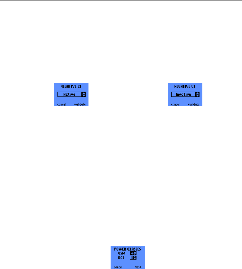
2.7.4 Negative C1
This function allows the mobile to camp on a cell with C1<0. You can browse through the following choices
with the scroll push-buttons ^ and v:
• Active: the mobile shall ignore the C1 criterion
• Inactive: the mobile shall comply with the GSM recommendations concerning the C1 criterion
The OK button (or the right one-touch button) validates the choice, while the C button (or the left one-touch
button) cancels and returns to the Forcing Functions general scrolling menu.
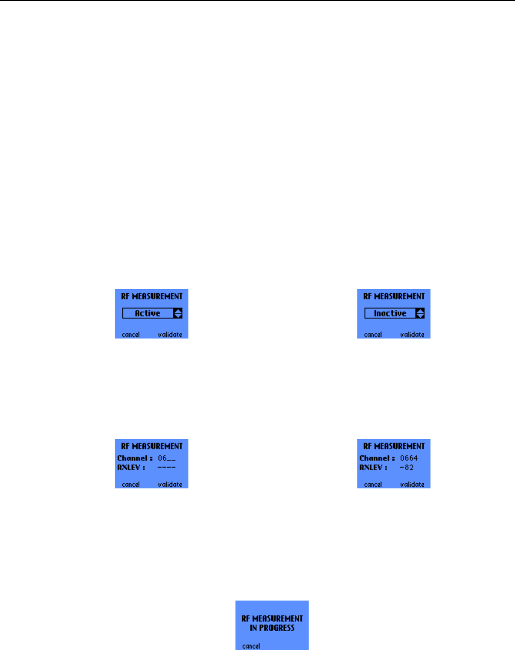
2.7.5 Set Power Class
This function allows to force the Power Class of the mobile. The possible choices are:
For GSM:
• 4 (2W or 33dBm, PL5)
• 5 (0.8W or 29 dBm, PL7)
• N: the mobile shall use its default power class
For DCS:
• 1 (1W or 30dBm, PL0)
• 2 (0.25W or 24dBm, PL3)
• N: the mobile shall use its default power class
Use the scroll buttons ^ and v to set the power class for the GSM frequency band then press the right
one-touch button to go to the next field and set the DCS power class. The OK button validates the choices,
whereas the C button (or left one-touch button) cancels them.
s
ERef. : SCT TMO LOG SPEC 163
Revision : B
Sec. Ref. :
Date : 2003-01-22
E. CONFIDENTIAL All rights of reproduction and disclosure reserved. Page 37 / 52
2.7.6 RF Measurement
NOTE: the BCCH forcing function and the RF MEASUREMENT function are mutually exclusive. If this
forcing function is active when activating RF MEASUREMENT, it will be automatically deactivated.
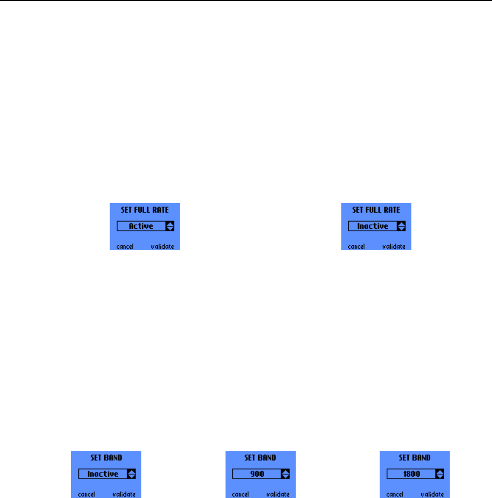
2.7.6.1 Activation/Deactivation screen
This function forces the mobile to perform RF power measurements on a given frequency. You can browse
through the following choices with the scroll push-buttons ^ and v:
• Active
• Inactive
The OK button (or the right one-touch button) validates the choice, while the C button (or the left one-touch
button) cancels and returns to the Forcing Functions general scrolling menu.
2.7.6.2 Frequency prompt and Field measurement screen
If the “Active” choice is validated this screen prompts for the frequency number on which the mobile shall
perform measurements and displays the measurement results when the channel number has been
validated with the OK button (or the right one-touch button). During the measurements, the OK button (or
the right one-touch button) also allows you to stop the forcing in order to enter another channel number.
2.7.6.3 Serial Link RF Measurement in progress
If the RF measurement mode was activated through the serial link of the trace mobile (see [1] for more
details about the serial link features and protocol), this screen is displayed to notify the user that a serial
link RF Measurement is in progress. Note that this screen is displayed regardless of the current menu or
the activated functions in the MMI: it depends only on the activation of the RF Measurement function
through the serial link.
Pressing the C button (or the left one-touch button) aborts the serial link RF Measurement function.
s
ERef. : SCT TMO LOG SPEC 163
Revision : B
Sec. Ref. :
Date : 2003-01-22
E. CONFIDENTIAL All rights of reproduction and disclosure reserved. Page 38 / 52
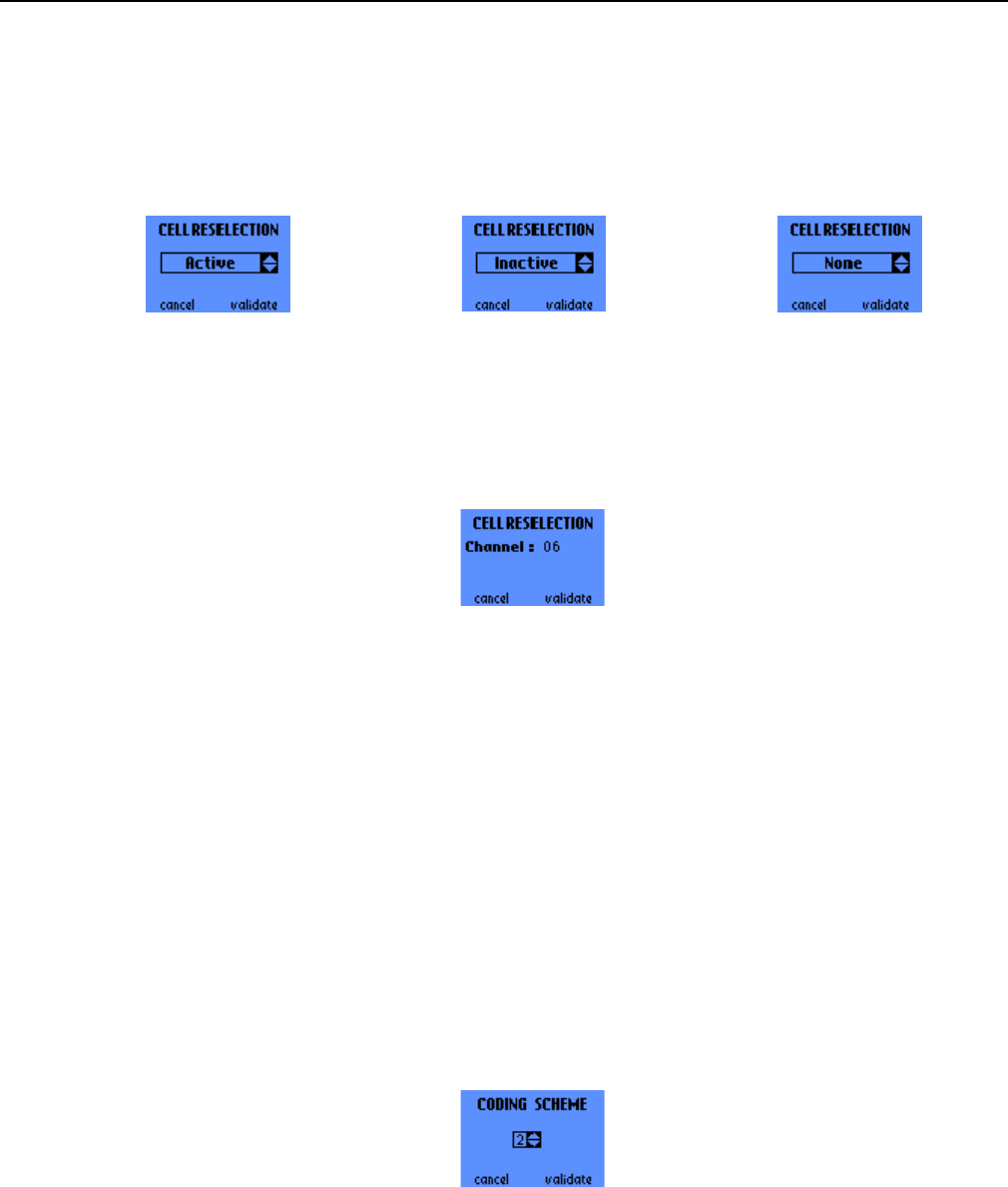
2.7.7 Set Full Rate
This function is used to force the mobile in Full Rate mode. The choices are:
• Active
• Inactive
The OK button (or right one-touch button) validates the choice, the C button (or left one-touch button)
cancels.
2.7.8 Set Band
This function is used to force the mobile on the 900 MHz or 1800 MHz band. The available choices are:
• 900
• 1800
• Inactive
The OK button (or right one-touch button) validates the choice, the C button (or left one-touch button)
cancels.
After the validation, the mobile must be powered off and on so that the new setting of the forcing
can be taken into account.
2.7.9 Set Cell Reselection
2.7.9.1 Activation/Deactivation screen
This screen is used to activate or deactivate the Set Cell Reselection function. The possible choices are:
• Active: the mobile will attempt to camp on a given frequency, using the Cell Re-selection procedure
• Inactive: the Cell Reselection forcing is deactivated
• None: this choice suppresses Cell Re-selection, i.e. the mobile will not use the Cell Re-selection
procedure, whatever happens.
The scroll push-buttons ^ and v are used to browse through these choices.
s
ERef. : SCT TMO LOG SPEC 163
Revision : B
Sec. Ref. :
Date : 2003-01-22
E. CONFIDENTIAL All rights of reproduction and disclosure reserved. Page 39 / 52
The OK button (or the right one-touch button) validates the choice, while the C button (or the left one-touch
button) cancels and returns to the Forcing Functions general scrolling menu.
NOTE: the Active and Inactive settings of this function can only be chosen in GSM IDLE mode.
2.7.9.2 BCCH channel prompt
If the “Active” choice is validated, a second screen prompts for the BCCH frequency number on which the
mobile shall attempt to camp using the cell re-selection procedure.
The OK button (or the right one-touch button) validates the choice and returns back in the Forcing
Functions general scrolling menu, while the C button (or the left one-touch button) deletes the previously
entered digit, or cancel the operation if no digit is present and returns to the Forcing Functions general
scrolling menu.
2.7.10 GPRS Downlink Coding Scheme forcing)
This function allows to force the Coding Scheme for Downlink data transfer. The possible choices are:
• 1
• 2
• 3 (to be tested: no BTS supports already this feature)
• 4 (to be tested: no BTS supports already this feature)
• N: No Coding Scheme forcing
Use the scroll buttons ^ and v to set the Downlink Coding Scheme. The OK button validates the choice,
whereas the C button (or left one-touch button) cancels it.
s
ERef. : SCT TMO LOG SPEC 163
Revision : B
Sec. Ref. :
Date : 2003-01-22
E. CONFIDENTIAL All rights of reproduction and disclosure reserved. Page 40 / 52
2.7.11 Set GPRS Auto Attach
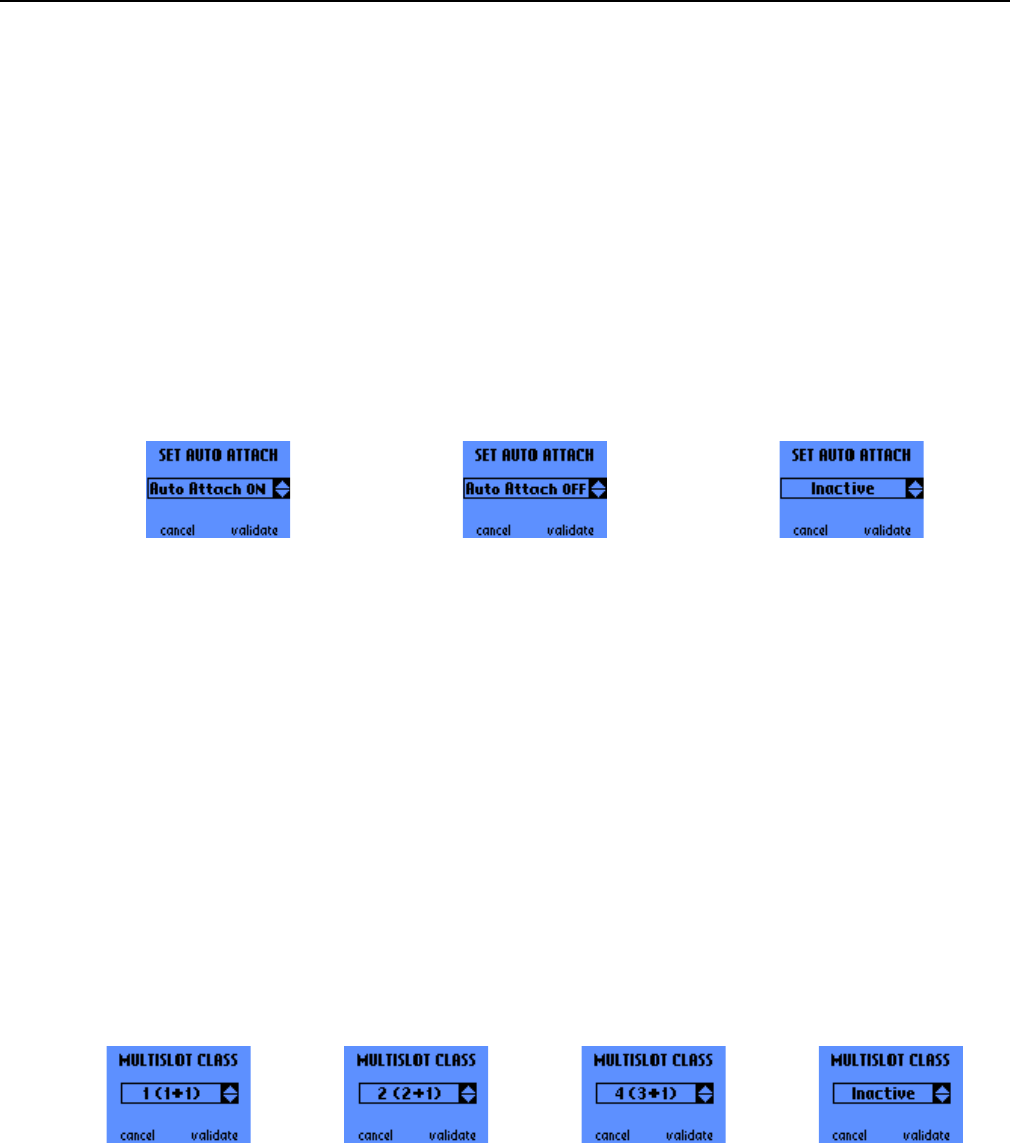
This function allows to specify whether the Mobile Station shall automatically attach to the GPRS network
at power-up or not. When this forcing function is set to OFF, the Mobile Station only attaches upon PDP
Context Activation. The following choices are available:
• Auto-Attach ON: the mobile shall attach at power-up
• Auto-Attach OFF: the mobile shall not attach at power-up
• Inactive: default behaviour
The scroll push-buttons ^ and v are used to browse through these choices.
The OK button (or the right one-touch button) validates the choice, while the C button (or the left one-touch
button) cancels and returns to the Forcing Functions general scrolling menu.
After the validation, the mobile must be powered off and on so that the new setting of the forcing
can be taken into account.
2.7.12 GPRS Multislot Class forcing
This function allows to force the Multislot Capability Class of the Mobile Station. The possible choices are:
• 1: Class 1 (1+1)
• 2: Class 2 (2+1)
• 4: Class 4 (3+1)
• Inactive: No Multislot Class forcing (default class)
Use the scroll buttons ^ and v to set the GPRS Multislot Class. The OK button (or right one-touch button)
validates the choices, whereas the C button (or left one-touch button) cancels them.
After the validation, the mobile must be powered off and on so that the new setting of the forcing
can be taken into account.
s
ERef. : SCT TMO LOG SPEC 163
Revision : B
Sec. Ref. :
Date : 2003-01-22
E. CONFIDENTIAL All rights of reproduction and disclosure reserved. Page 41 / 52
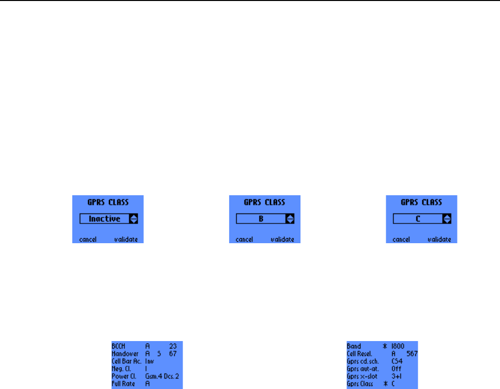
2.7.13 GPRS Class forcing
This function allows to force the GPRS Class of the Mobile Station. The possible choices are currently:
• B: MS GPRS Class B
• C: MS GPRS Class C
• Inactive: No GPRS Class forcing (default class)
After the validation, the mobile must be powered off and on so that the new setting of the forcing
can be taken into account.
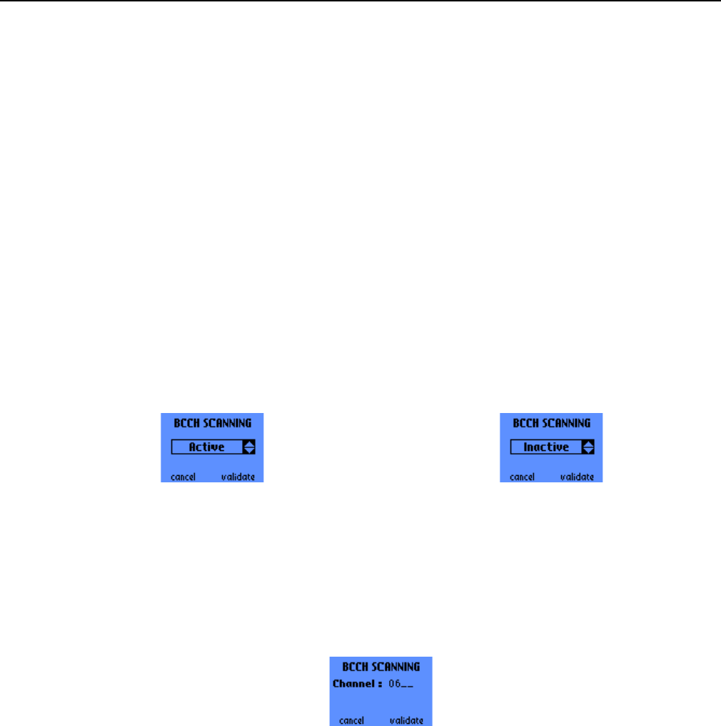
2.7.14 Summary
This choice allows to display the forcing summary screens :
The scroll push-buttons ^ and v are used to browse through the successive screens. The C button returns
to the forcing functions menu.
The first column indicates the forcing function and the second one indicates the forcing current state. We
can also find right next to the current state, some additional information depending on the forcing function.
The different possibilities are described below:
• BCCH: Set BCCH
► A: Active I: Inactive
► BCCH Channel (only if the Set BCCH forcing is Active)
• Handover: Set Handover
► A: Active I: Inactive N: None
► C: Cyclical S: Single
► BCCH Channel (only if the Set Handover forcing is Active)
• Cell Bar Ac.: Cell Bar Access
► A: Active I: Inactive Inv: Inverse
• Neg. C1: Negative C1
► A: Active I: Inactive

s
ERef. : SCT TMO LOG SPEC 163
Revision : B
Sec. Ref. :
Date : 2003-01-22
E. CONFIDENTIAL All rights of reproduction and disclosure reserved. Page 42 / 52
• Power Cl.: Set Power Class
► GSM. : Power Class for GSM : 4, 5 or N
► DCS. : Power Class for DCS : 1, 2 or N
• Full Rate: Set Full Rate
► A: Active I: Inactive
• Band: Set Band
► ✴
✴✴
✴: We have to restart the Mobile Station in order to activate the forcing selection.
► 900: GSM Band 1800: DCS Band I: Inactive
• Cell Resel.: Set Cell Reselection
► A: Active I: Inactive Inv: Inverse
► BCCH Channel (only if the Set Cell Reselection forcing is Active)
• Gprs cd.sch.: Set GPRS Coding Scheme ()
► CS*: Coding Scheme 1, 2, 3, 4 or N
• Gprs aut-at.: Set GPRS Auto Attach ()
► ✴
✴✴
✴: We have to restart the Mobile Station in order to activate the forcing selection.
► I: Inactive OFF: Auto Attach OFF ON: Auto Attach ON
• Gprs x-slot: Set GPRS Multislot Class )
► ✴
✴✴
✴: We have to restart the Mobile Station in order to activate the forcing selection.
► I: Inactive 1+1: Class 1(1+1) 2+1: Class 2(2+1) 3+1: Class 4(3+1)
• Gprs Class: Set GPRS Class )
► ✴
✴✴
✴: We have to restart the Mobile Station in order to activate the forcing selection.
► I: Inactive B: MS GPRS Class B C MS GPRS Class C
s
ERef. : SCT TMO LOG SPEC 163
Revision : B
Sec. Ref. :
Date : 2003-01-22
E. CONFIDENTIAL All rights of reproduction and disclosure reserved. Page 43 / 52
2.8 BCCH SCANNING
NOTE: the BCCH forcing function and the BCCH SCANNING function are mutually exclusive. If this forcing
function is active when activating BCCH SCANNING, it will be automatically deactivated.
2.8.1 Activation/Deactivation screen
This function is used to scan the RF channels. The available choices are:
• Active
• Inactive
The OK button (or right one-touch button) validates the choice, the C button (or left one-touch button)
cancels.
2.8.2 Beginning channel input screen
If “Active” choice if validated, this screen prompts for the beginning channel. The BCCH SCANNING will
start on this channel and continue on the following RF frequencies.
The OK button (or right one-touch button) validates the choice, the C button cancels the previous digit
entered, or goes back to the previous screen if there is no digit to delete. The left one-touch button goes
back to the previous screen.
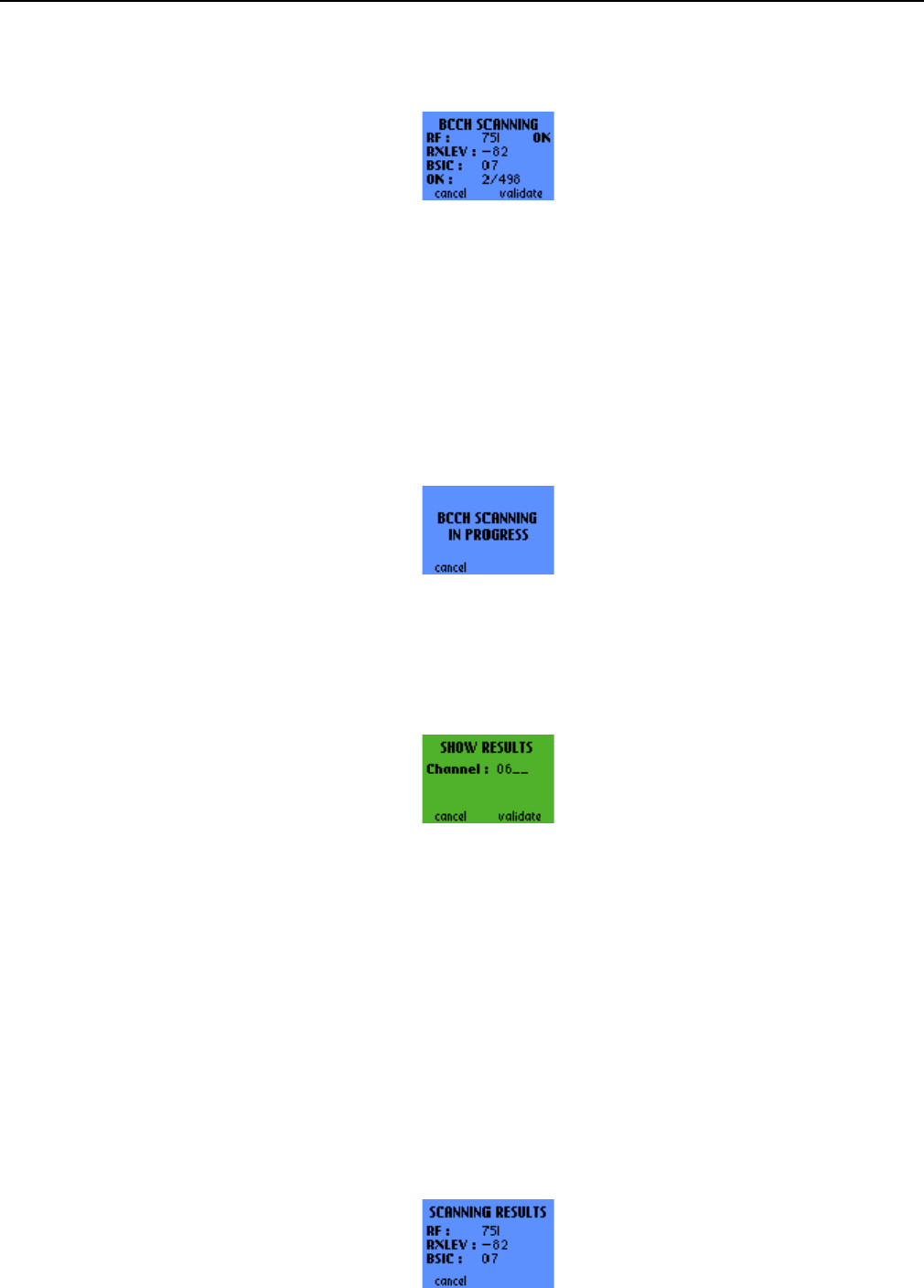
2.8.3 BCCH Scanning in progress screens
2.8.3.1 BCCH Scanning initiated via the MMI
After validation of the RF channel to begin with, this screen displays for the previously scanned channel
the following parameters:
• RF channel number, with an indication of the nature of the channel : OK means that the channel is a
BCCH, NOK means that the channel is not a BCCH
• RX LEV: RF power measurement (in dBm)
• BSIC: color code of the Base Station. If the channel is not a BCCH, the value of this parameter is
replaced by “--“.
• Number of BCCH found / total number of channels
s
ERef. : SCT TMO LOG SPEC 163
Revision : B
Sec. Ref. :
Date : 2003-01-22
E. CONFIDENTIAL All rights of reproduction and disclosure reserved. Page 44 / 52
Pressing the C button (or the left one-touch button) returns to the beginning channel input screen (see
2.8.2). The OK button (or the right one-touch button) stops the scanning and displays the results of the
scanning.
2.8.3.2 BCCH Scanning initiated via the Serial Link
Furthermore, during a scanning that was activated through the serial link of the trace mobile (see [1] for
more details about the serial link features and protocol), this screen is displayed to notify the user that a
serial link BCCH scanning is in progress. Note that this screen is displayed regardless of the current menu
or the activated functions in the MMI: it depends only on the activation of the Scanning function through the
serial link.
Pressing the C button (or the left one-touch button) aborts the serial link scanning.
2.8.4 Beginning channel for results display
Before actually displaying the results of the scanning, the mobile asks for the beginning channel number.
The C button (or the left one-touch button) cancels the digit entered previously. The OK button (or right
one-touch button) validates the beginning frequency.
2.8.5 BCCH Scanning results screen
This screen shows the measured parameters for every channel beginning with the channel number
previously entered:
• RF: channel number
• RXLEV: RF power measurement (in dBm). If the corresponding channel was not scanned during the
previous scan, this value is replaced by “----“.
• BSIC: color code of the Base Station. If the corresponding channel is not a BCCH or was not scanned
during the previous scan, this value is replaced by “----“.
To browse through the successive results screen, use the scroll push-buttons ^ and v.
s
ERef. : SCT TMO LOG SPEC 163
Revision : B
Sec. Ref. :
Date : 2003-01-22
E. CONFIDENTIAL All rights of reproduction and disclosure reserved. Page 45 / 52
The C button (or the left one-touch button) cancels the digit entered previously brings back to the
beginning channel screen for results display (see 2.8.4).
2.9 QOS INFO
This menu contains 4 entries:
• FER full
• T3212
• Handover Counter
• EFR
The scroll push-buttons ^ and v are used to browse through the menu.
2.9.1 FER full
This function gives the FER (Frame Erasure Rate) in percentage of the speech frames erased over the last
four measurement periods.
When this value is not applicable (for instance in Idle mode), the FER value is replaced by “----“.
The C button (or the left one-touch button) brings back to the QoS Info scrolling menu.
2.9.2 T3212
This screen displays the following parameters:
• max_retrans: the maximum allowed number of retransmissions of a burst over the RACH (Random
Access Channel) is equal to max_retrans. The displayed values are: RACH retransmission counter
value / max_retrans value. See [04.08] for more details.
• T3212: the T3212 counter indicates the timeout (in decihour) value for the periodic updating. It ranges
from 1 to 255. Inf means infinite timeout, i.e. the mobile shall not perform any periodic updating. See
[04.08] for more details.
The C button (or the left one-touch button) returns to the QoS Info scroll menu.
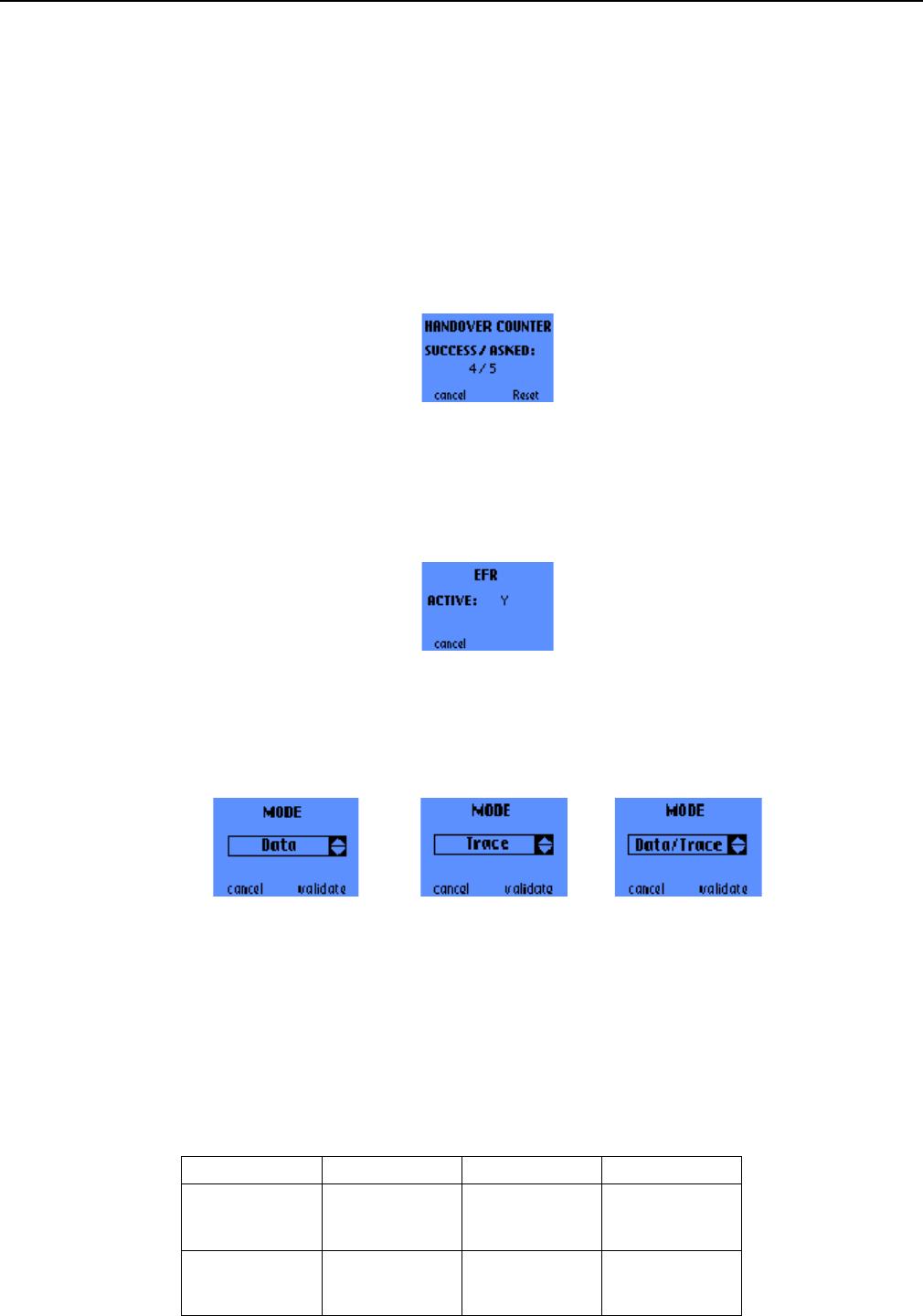
s
ERef. : SCT TMO LOG SPEC 163
Revision : B
Sec. Ref. :
Date : 2003-01-22
E. CONFIDENTIAL All rights of reproduction and disclosure reserved. Page 46 / 52
2.9.3 Handover Counter
This screen displays the number of succeeded and attempted handovers. The C button (or the left one-
touch button) leads back to the QoS Info scrolling menu.
The scroll push-button ^ may be used to go straight to the Handover forcing mode screen (see 2.7.2.2).
The right one-touch button resets the Handover Counter.
2.9.4 EFR
This screen indicates whether the EFR (Enhanced Full Rate) speech codec is active or not (Y or N).
The C button (or the left one-touch button) returns to the QoS Info scroll menu.
2.10 SERIAL LINK SETUP
In this menu, 3 modes are available :
• DATA : The serial link of the mobile is dedicated to standard DATA messages.
• TRACE : The serial link is dedicated to trace messages.
• DATA/TRACE : The main serial link is in DATA mode. Traces are provided on the second serial link.
(only available with OT 96xx)
According to the mobile serial link setup, the serial links operate as follow :
Mode DATA TRACE DATA/TRACE
SL 1 DATA TRACE DATA
SL 2 inactive inactive TRACE

s
ERef. : SCT TMO LOG SPEC 163
Revision : B
Sec. Ref. :
Date : 2003-01-22
E. CONFIDENTIAL All rights of reproduction and disclosure reserved. Page 47 / 52
2.11 RF SCANNING IN PROGRESS SCREEN
This screen indicates that the mobile is in RF Scanning mode. This mode is only available through the
serial link interface of the mobile (see [1] for more details). Note that this screen is displayed regardless of
the current menu or the activated functions in the MMI: it depends only on the activation of the RF
Scanning function through the serial link.
Pressing the C button (or the left one-touch button) aborts the serial link RF Scanning function.
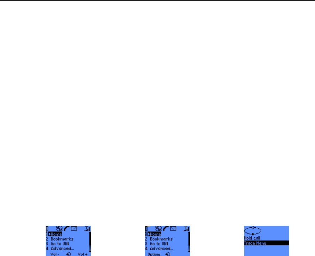
s
ERef. : SCT TMO LOG SPEC 163
Revision : B
Sec. Ref. :
Date : 2003-01-22
E. CONFIDENTIAL All rights of reproduction and disclosure reserved. Page 48 / 52
3. SWITCHING BETWEEN WAP BROWSER AND TRACE SCREENS
3.1 ESCAPING FROM THE WAP BROWSER
3.1.1 Escaping the WAP browser – general procedure
The WAP Browser can be escaped in order to go in the Trace Menu screens by pressing for a few
secondes the ‘#’ key. This will start the Trace Menu, or if the user had previously escaped from a Trace
Menu screen, this will go back to that screen.
3.1.2 Escaping the WAP browser during a voice call
During a voice call, the WAP Browser can be escaped using the following procedure : press the middle
soft-key, then press the left soft-key (« Options ») then select Trace Menu and press OK
3.2 STARTING WAP TRANSFER FROM THE TRACE MENU SCREENS
In some Trace Menu screens you may switch to the WAP browser or start WAP transfers in the
background (i.e. without leaving the Trace Screen).
The actions described below are only possible when in the trace screens of the following menus:
• GPRS Info
• Network
• QoS Info
3.2.1 Switching to the WAP browser
A normal press on the ‘@’ middle soft-key switches to the WAP browser. If necessary the browser is
started.
3.2.2 Starting the homepage connection
A long press on the ‘@’ middle soft-key starts the connection to the homepage configured for the current
WAP provider, without leaving the current trace screen.

s
ERef. : SCT TMO LOG SPEC 163
Revision : B
Sec. Ref. :
Date : 2003-01-22
E. CONFIDENTIAL All rights of reproduction and disclosure reserved. Page 49 / 52
3.2.3 Starting a bookmark connection
A press on any non-zero digit brings up the dialing screen. Then, pressing the ‘@’ middle soft-key starts
the connection to the bookmark entry corresponding to the entered digit, without leaving the current trace
screen.
s
ERef. : SCT TMO LOG SPEC 163
Revision : B
Sec. Ref. :
Date : 2003-01-22
E. CONFIDENTIAL All rights of reproduction and disclosure reserved. Page 50 / 52
4. ANNEX: GPRS QOS PARAMETERS DEFINITION
This Annex defines and explains how some GPRS variables displayed in screens of the GPRS Info menu
of calculated and refreshed.
4.1 DATA TRANSFER 2ND SCREEN (LLC) PARAMETERS
This screen is described in 2.5.3.2.
4.1.1 Retransmitted LLC Frame Rate
The Retransmitted LLC Frame Rate is computed over a period of 1 second. It is defined as follows:
Direction Definition
UPLINK Retrans. Frame Rate = NRETRANS / NTOTAL
where:
• N
RETRANS = number of frames that are not sent for the 1st time
• N
TOTAL = total number of transmitted frames
DOWNLINK Retrans. Block Rate = NLOST / NTOTAL
where:
• N
LOST = number of frames detected as lost. A frame or a group of frames is considered
as lost when the OT detects a gap in the frame sequence
• N
TOTAL = number of frames that have been supposedly sent. It is estimated based on
the Sequence Number of the latest received frame. As a consequence it does not
include retransmitted frames.
The Retransmitted LLC Frame Rate is filtered according to the following criteria:
• it is reported only if at least one LLC SAPI is in Acknowledged mode
• it is reported only if NTOTAL has changed over the reporting period.
4.1.2 LLC Data throughput
The LLC Data throughput traces are focused on the capacity that is offered by the LLC layer to upper layer
in the User plane. As a consequence the LLC Data throughputs are defined as follows:
• only I and UI frames are considered
• only SAPI 3, 5, 9, and 11 are considered (i.e. User SAPIs)
• in LLC Acknowlegded mode retransmissions are not take into account
• LLC header parts are not taken into account
The LLC throughputs are computed over a period of 1 second and reported according to the following
criteria:
s
ERef. : SCT TMO LOG SPEC 163
Revision : B
Sec. Ref. :
Date : 2003-01-22
E. CONFIDENTIAL All rights of reproduction and disclosure reserved. Page 51 / 52
• when the mobile is in READY mode, LLC Data Throughputs are reported at the end of every reporting
period
• when the mobile is not in READY mode, LLC Data Throughputs are reported only if the number of
transmitted bytes has changed over the reporting period
4.1.3 Total LLC frames transmitted
The Total number of LLC frames transmitted is defined as follows:
• only I and UI frames are considered
• only SAPI 3, 5, 9, and 11 are considered (i.e. User SAPIs)
• in LLC Acknowlegded mode retransmissions are not take into account
It is reported every second, unless it has not changed over the reporting period.
4.2 DATA TRANSFER 3RD SCREEN (RLC) PARAMETERS
This screen is described in 2.5.3.3.
4.2.1 Retransmitted RLC Block Rate
The Retransmitted RLC Block Rate is computed over a period of 1 second. It is defined as follows:
Direction Definition
UPLINK Retrans. Block Rate = NNACKED / (NFIRST TRANS + NNACKED)
where:
• N
NACKED = number of blocks sent in the NACKED state
• N
FIRST TRANS = number of blocks that have been transmitted for the 1st time
DOWNLINK Retrans. Block Rate = NLOST / NTOTAL
where:
• N
LOST = number of blocks detected as lost. A block or a group of blocks is considered
as lost when the OT detects a gap in the block sequence
• N
TOTAL = number of blocks that have been supposedly sent. It is estimated based on
the Sequence Number of the latest received block. As a consequence it does not
include retransmitted blocks.
The Retransmitted RLC Block Rate is filtered according to the following criteria:
• in the Uplink: it is reported only if (NFIRST TRANS + NNACKED) has changed over the reporting period.
• in the Downlink: it is reported only if NTOTAL has changed over the reporting period.
4.2.2 RLC/MAC Data throughput traces
The RLC/MAC Data throughput takes into account RLC/MAC Data blocks only, including retransmissions
and header parts. It is computed over a period of 1 second and reported according to the following criteria:
• when the mobile is in READY mode, RLC/MAC Data Throughputs are reported at the end of every
reporting period

s
ERef. : SCT TMO LOG SPEC 163
Revision : B
Sec. Ref. :
Date : 2003-01-22
E. CONFIDENTIAL All rights of reproduction and disclosure reserved. Page 52 / 52
• when the mobile is not in READY mode, RLC/MAC Data Throughputs are reported only if the number
of transmitted bytes has changed over the reporting period
4.2.3 Total RLC blocks transmitted
The Total number of RLC blocks transmitted is defined as follows:
• only DATA blocks are take into account
• all received or sent blocks are considered, including those blocks that are retransmitted in NACKED or
PENDING ACK state
It is reported every second, unless it has not changed over the reporting period.
4.3 MEASUREMENT INFO PARAMETER
This screen is defined in 2.5.5.
The Downlink RLC BLER is computed over a period of 1 second. It is defined as follows :
BLER = NERRORED / NTOTAL
where:
• N
ERRORED = number of data blocks received with a bad CRC and a TFI corresponding to the current
downlink TFI allocated to the mobile
• N
TOTAL = total number of data blocks received with a TFI corresponding to the current downlink TFI
allocated to the mobile
NOTE: the received RLC/MAC blocks are filtered according to the PAYLOAD TYPE and TFI fields of their
RLC/MAC headers. Those fields can be affected by transmission errors, so the two parameters above
(NERRORED and NTOTAL) can only be estimated. As a consequence the reported value must be considered
as an estimation of the Block Error Rate of the radio link between the network and that particular mobile.