Salutron HRM3300 Heart rate module 3300 series User Manual
Salutron Inc. Heart rate module 3300 series
UserManual.wiki
>
Salutron
>
HRM3300 User Manual
User Manual
Navigation menu
Upload a User Manual
Namespaces
Wiki Guide
HTML
PDF
Info
Views
User Manual
Discussion / Help
Navigation


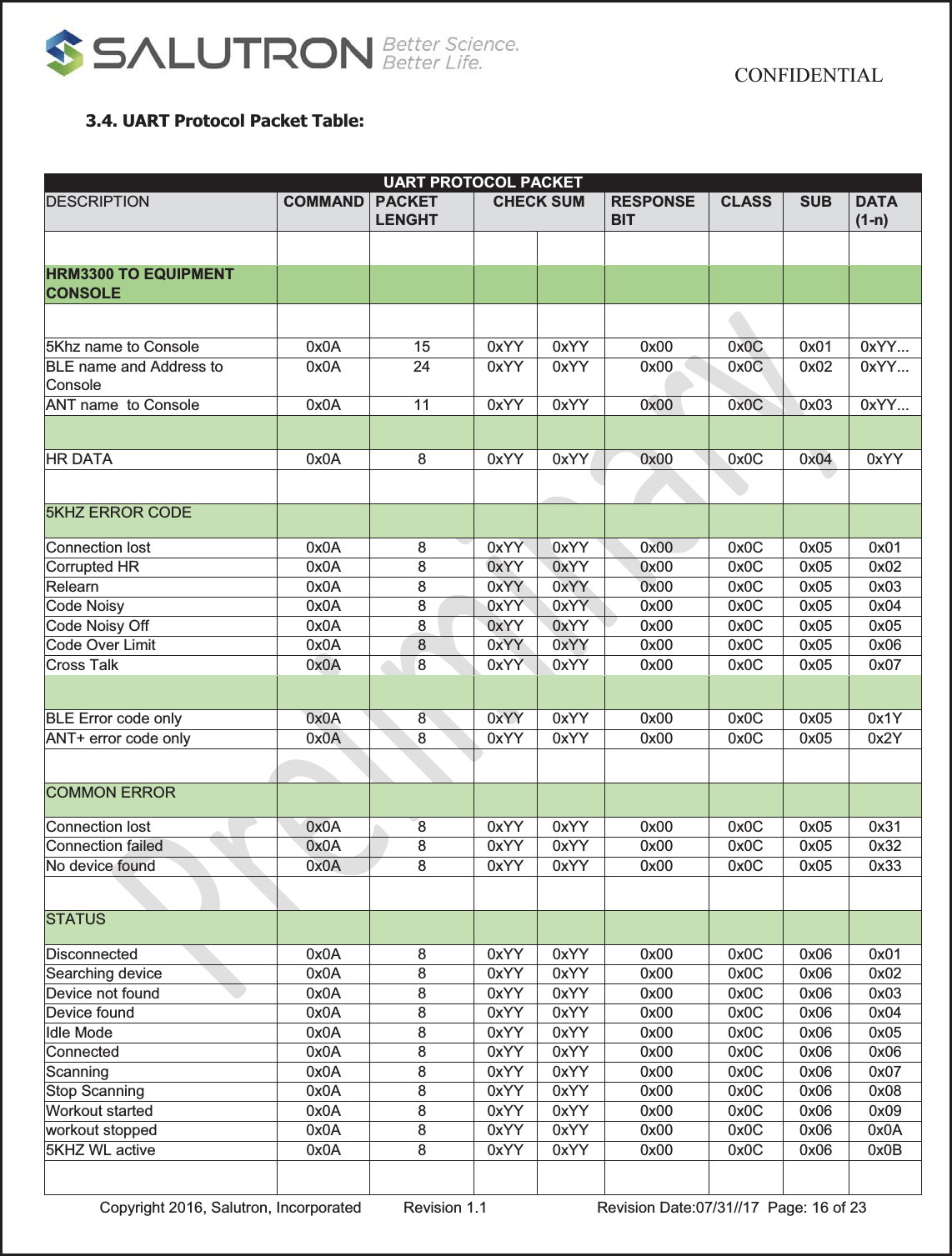
![CONFIDENTIAL Copyright 2016, Salutron, Incorporated Revision 1.1 Revision Date:07/31//17 Page: 14 of 233. UART COMMUNICATION PROTOCOL PACKETS 3.1. Packets The uart protocol packets contain data that will be used as an interface between the HRM3300 and the equipment console. A maximum of twenty four bytes and a minimum of eight bytes are used during Uart communication. Fletcher checksum reference: https://en.wikipedia.org/wiki/Fletcher%27s_checksum For 5kHz analog strap, the name to be transmitted will be “5kHz HRM”. Below is the UART packet: A response bit when set means the receiver is obliged to response acknowledgement when package is received from the transmitting Uart port START COMMAND PACKET LEN CHECK SUM RESPONSE BIT CLASS SUB DATAx Type Size in bytes Description START COMMAND 1 Start byte PACKET LEN 1 Number of bytes in a packet CHECK SUM 2 Fletcher checksum RESPONSE BIT 1 Response bit CLASS 1 Packet Class type SUB CLASS 1 Packet sub-class type DATA 17 BLE advertising name and BLE address with “0x1F” separator between name and address 8 5Khz HRM name 2 ANT+ ID 1 Other data 3.2. Example of Sending Packets Equipment Console Usage: Sending packet name to equipment console Format: [Start Command] [Packet Size] [Fletcher check sum low byte] [Fletcher check sum high byte] [Response bit] [Class] [Sub Class] [Name 1st byte]](https://usermanual.wiki/Salutron/HRM3300/User-Guide-3614798-Page-14.png)
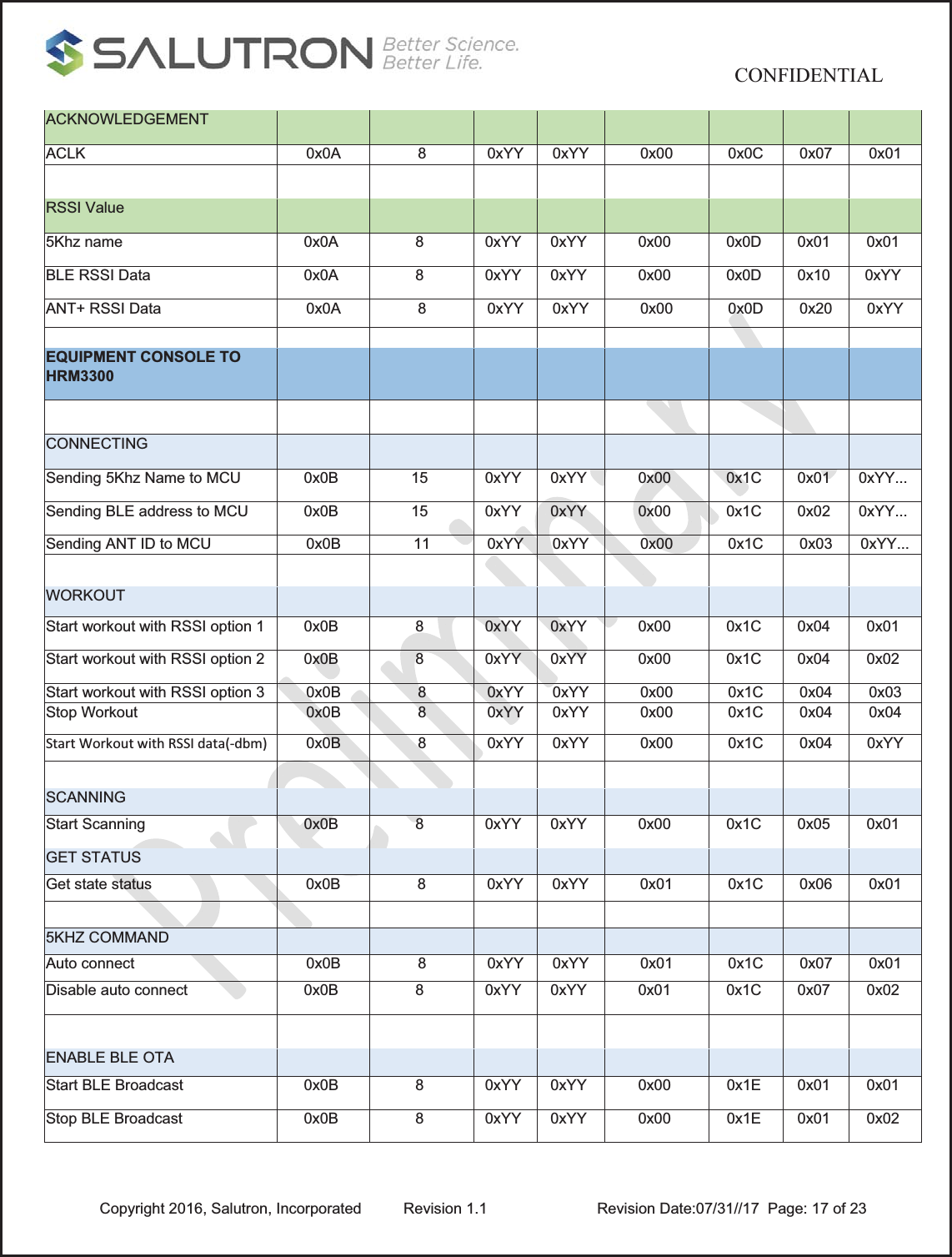
![CONFIDENTIAL Copyright 2016, Salutron, Incorporated Revision 1.1 Revision Date:07/31//17 Page: 15 of 23[Name … byte] [Name xth byte] Packet: ex. 5Khz advertising name = “5kHz HRM” [0x0A] [0x0F] [0xYY] [0xZZ] [0x0C] [0x00] [0x01] [0x35] [0x6B] [0x48] [0x7A] [0x20] [0x48] [0x52] [0x4D] 3.3. Example of Sending Packet to HRM3300 Usage: Sending selected packet name to HRM3300 Format: [Start Command] [Packet Size] [Fletcher check sum low byte] [Fletcher check sum high byte] [Response bit] [Class] [Sub Class] [Name 1st byte] [Name … byte] [Name xth byte] Packet: ex. 5Khz advertising name = “5kHz HRM” [0x0B] [0x0F] [0xYY] [0xZZ] [0x00] [0x1C] [0x01] [0x35] [0x6B] [0x48] [0x7A] [0x20] [0x48] [0x52] [0x4D]](https://usermanual.wiki/Salutron/HRM3300/User-Guide-3614798-Page-15.png)