User Manual
HRM8700
Combo Heart Rate Module
User Guide
FCC ID:N7P-HRM8700
IC:10274A-HRM8700
FCC ID:N7P-HRM8700FCC ID:N7P-HRM8700FCC ID:N7P-HRM8700FCC ID:N7P-HRM8700
IC:10274A-HRM8700IC:10274A-HRM8700IC:10274A-HRM8700IC:10274A-HRM8700

CONFIDENTIAL
Copyright 2017, Salutron, Inc. Revision 0.1 Revision Date: 07/23//17 Page: 2 of 21
Revision History:
Revision Release
date Description B
y
0.1 07/23/17 Preliminary Draft BC

CONFIDENTIAL
Copyright 2017, Salutron, Inc. Revision 0.1 Revision Date: 07/23//17 Page: 3 of 21
Contents
General Description .............................................................................................................................. 4
Features: ............................................................................................................................................. 4
Physical Dimensions: Inches (mm) ......................................................................................................... 5
Connection Diagram: (Typical) .............................................................................................................. 6
Electrical Characteristics: ...................................................................................................................... 7
ECG Measurement: ............................................................................................................................... 7
5KHZ Wireless Specification: ................................................................................................................. 7
BLE/ANT+ Specification: ....................................................................................................................... 7
1. UART COMMUNICATION PROTOCOL: ................................................................................................. 9
1.2.Block Diagram .......................................................................................................................................... 9
2. OPERATION ..................................................................................................................................... 9
2.1. Description............................................................................................................................................... 9
2.2. UART Specification .................................................................................................................................. 9
2.3. Equipment Assomptions ........................................................................................................................ 10
2.4. HRM8700 default configuration ............................................................................................................. 10
2.5. Equipment and HRM8700 Operations ................................................................................................... 11
2.6. HRM8700 OTA. ...................................................................................................................................... 12
3. UART COMMUNICATION PROTOCOL PACKETS ................................................................................... 13
3.1. Packets .................................................................................................................................................. 13
3.2. Example of Sending Packets Equipment Console .................................................................................. 13
3.3. Example of Sending Packet to HRM8700 .............................................................................................. 14
Appendix A : Grounding and ESD Recommendations .............................................................................. 15
Appendix B: HRM8700 Placement Guideline ........................................................................................... 18
FCC/IC statement ................................................................................................................................ 20
FCC statement .............................................................................................................................................. 20
IC statement ................................................................................................................................................. 20
CONFIDENTIAL
Copyright 2017, Salutron, Inc. Revision 0.1 Revision Date: 07/23//17 Page: 4 of 21
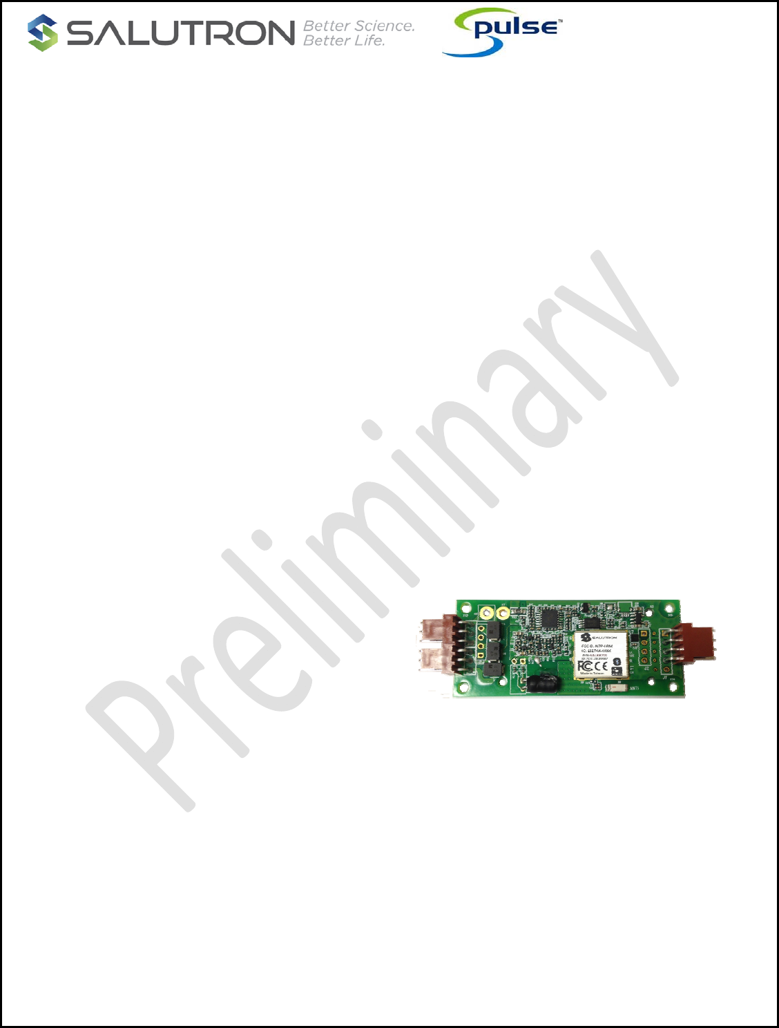
Model HRM8700
Wireless Heart Rate Monitor Specifications
General Description
The Model HRM8700 is a wireless receiver and
Handgrip Heart Rate Monitor Combo. It is
designed to manage and support ECG contact
heart rate and the reception of wireless heart
rate data from BLE, ANT+, standard 5kHz
chest straps or wearable heart rate
transmitters or devices.
Once enabled by the Console, the HRM8700
actively scans for local HR transmitter signals,
and supports a user selection/pairing protocol
processed by the Console.
Once a HR transmitter is selected/paired, the
HRM8700 streams the user heart rate data
until the end of the workout session, then
‘unpairs’.
The HRM8700 contact heart rate monitor can
quickly and accurately measure the heart rate
from an ECG signal under noisy environments.
The HRM8700 simultaneously processes
Handgrip Heart Rate and Wireless Heart Rate
data. Either can be specified as the priority
heart rate.
Features:
Direct connection to equipment; no phone
device or app ‘middleman’
Support ECG contact heart rate
Supports multiple inbound sources for HR:
BLE, ANT+, 5kHz
Automatic proximity sensing to minimizing
interference from competing wireless HR
signals
Console controllable proximity commands
allowing ‘customization’ of the scanning
proximity during integration development of
the HRM8700 into the console
Simplified user pairing routine
Future-proof: OTA updateable to support
future features (based on console pass-
through, if available)
Interface: UART, custom command protocol
The HRM8700 series combo heart rate module
delivers high performance ECG contact and
telemetry heart rate monitoring - for both
commercial/club and home cardio equipment
applications.
The HRM8700 communicates and passes the
heart rate data from the heart rate monitor to the
equipment console through proprietary UART
protocol.
The HRM8700 series offers a special proximity
pairing feature that allows the equipment console
to discover only the HR transmitting devices in
close proximity. This feature minimizes unwanted
devices and speeds up the pairing process,
especially useful in health club environments
where there may be multiple BLE or ANT+
devices present. After successful pairing, the
reception distance will automatically increase to
maximum range.
The HRM8700 receiver also supports legacy S-
pulse contact heart rate and 5kHz chest strap
data reception. It utilizes Salutron’s proprietary
Digital Crosstalk Control and Digital Noise Filter
algorithms that can filter out unwanted competing
chest strap signals. This supports better wireless
reception and reduce 5kHz noise from potentially
unfriendly high ‘noise’ environments coming from
power systems and console electronics.
o ECG handgrip contact heart rate with R-R
interval output (Optional)
o BLE smart and ANT+ data reception
o Standard 5.3kHz chest strap, coded and un-
coded signal reception
o Proximity pairing feature.
o UART communication protocol
o Stationary Bike FE-C support
o 3~6V operation.
o RoHS compliant.
CONFIDENTIAL
Copyright 2017, Salutron, Inc. Revision 0.1 Revision Date: 07/23//17 Page: 5 of 21
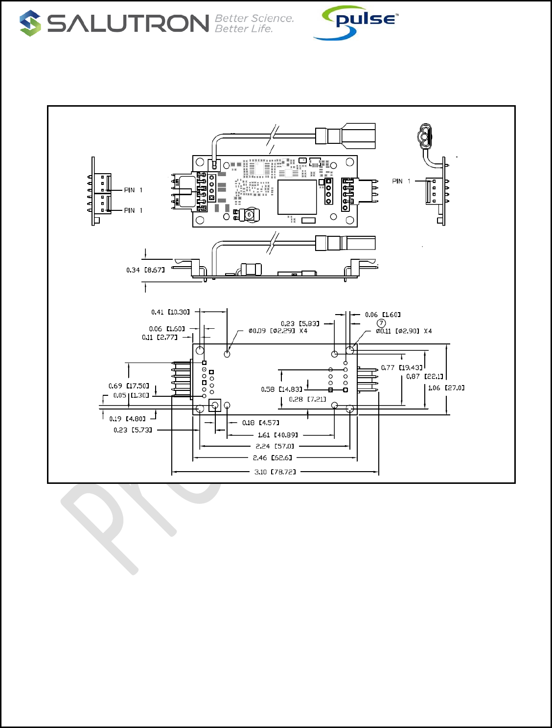
Physical Dimensions: Inches (mm)
Figure1:Physicaldimensions
The physical properties of the HRM8700 allow for easy integration in your existing equipment. See above
picture for the physical dimensions of the board. Preferred headers may be specified, with Salutron’s
consultation. Because of its small size and weight, the board can be fastened using adhesive tape, or #2
screws.
CONFIDENTIAL
Copyright 2017, Salutron, Inc. Revision 0.1 Revision Date: 07/23//17 Page: 6 of 21
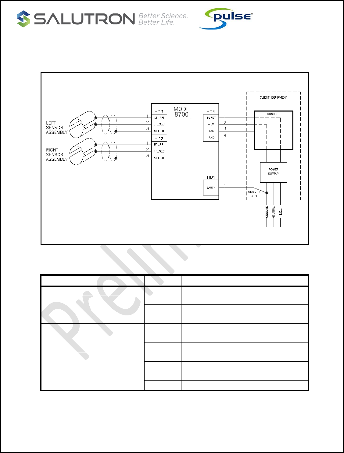
Connection Diagram: (Typical)
Figure 2: Connection Diagram
TYPE PIN No. DESCRIPTION
HD1 – Ground Strap 1 Earth Ground
HD2 – Right Sensor
1 RA, right primary sensor
2 LL, common sensor
3 Shield
HD3 – Left Sensor
1 LA, left primary sensor
2 LL, common sensor
3 Shield
J1 – Main
1 GND
2 +5V
3 TXD
4 RXD
CONFIDENTIAL
Copyright 2017, Salutron, Inc. Revision 0.1 Revision Date: 07/23//17 Page: 7 of 21
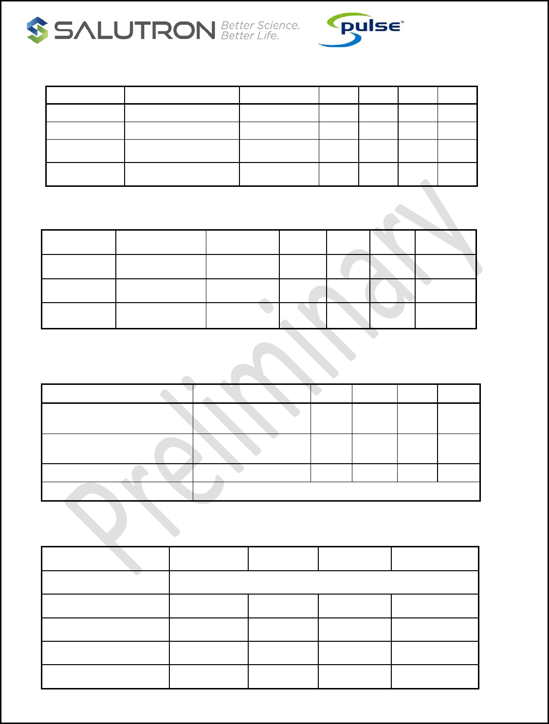
Electrical Characteristics:
Symbol Parameter Conditions Min. Typ. Max. Units
VS Supply voltage - 3 5 6 V
IS Supply current Vcc = 5V 5.2 7.5 10.5 mA
To Operating Temperature - -10 - 60 °C
Ts Storage Temperature - -40 - 85 °C
ECG Measurement:
Symbol Parameter Conditions Min. Typ. Max. Units
HR Heart EC Simulator 30 - 240 BPM
CHR sensor ECG sensitivity 0.1 - - mV
Ta Acquisition Time Bike/treadmill 3 5 10* seconds
*Among the contributing factors resulting in long HR acquisition are motion induced physiological artifact, electrical disturbance from
control electronics, transient motor drive loading, and skin contamination via hand cream, cosmetics, and dust,
5KHZ Wireless Specification:
Parameter Conditions Min. Typ. Max. Units
5KHZ Wireless reception range Noise free environment 31
80 35
90 39
100 Inches
cm
5KHZ Wireless reception
frequency T= 25ºC, Vcc =5.0V 4.8 5.3 5.9 KHz
Heart rate detection T= 25ºC, Vcc =5.0V 30 - 240 BPM
Output format UART Protocol
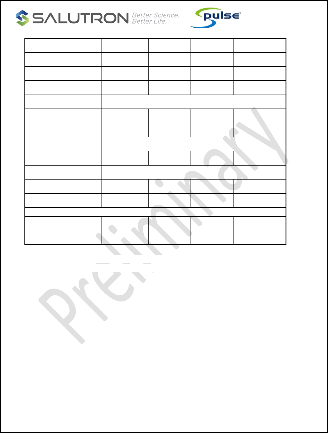
BLE/ANT+ Specification:
Minimum Typical Maximum Unit
HR Measurement
Range 30 - 240 beats per minute
Frequency 2402 - 2480 MHz
Center Frequency - 2440 - MHZ
Channel Bandwidth - - 2 MHZ
CONFIDENTIAL
Copyright 2017, Salutron, Inc. Revision 0.1 Revision Date: 07/23//17 Page: 8 of 21
Low speed Crystal Freq - 32.768 - KHZ
High speed Crystal Freq - 32 - MHZ
Channel Spacing - 2 - MHZ
No. of channels used - - 40 Channels
Modulation GFSK
Output power -20 - 4 dBm
Open Air range - - 10 Meter
Power Consumption Vdd=5.0V @ 25°C
Standby mode - 5 - mA
Operation Modes
Device Searching Mode - 10 10.5 mA
Heart rate Data transfer - 5 5.5 mA
2.4GHZ Transmission
distance (line of sight)*
65
20
-
-
-
-
Feet
Meter
*Note:thenatureofphysicalobstructionsand/or2.4GHzradiointerferenceinthesurroundingarea
couldaffectthereceptionandtransmissionrange.
CONFIDENTIAL
Copyright 2017, Salutron, Inc. Revision 0.1 Revision Date: 07/23//17 Page: 9 of 21
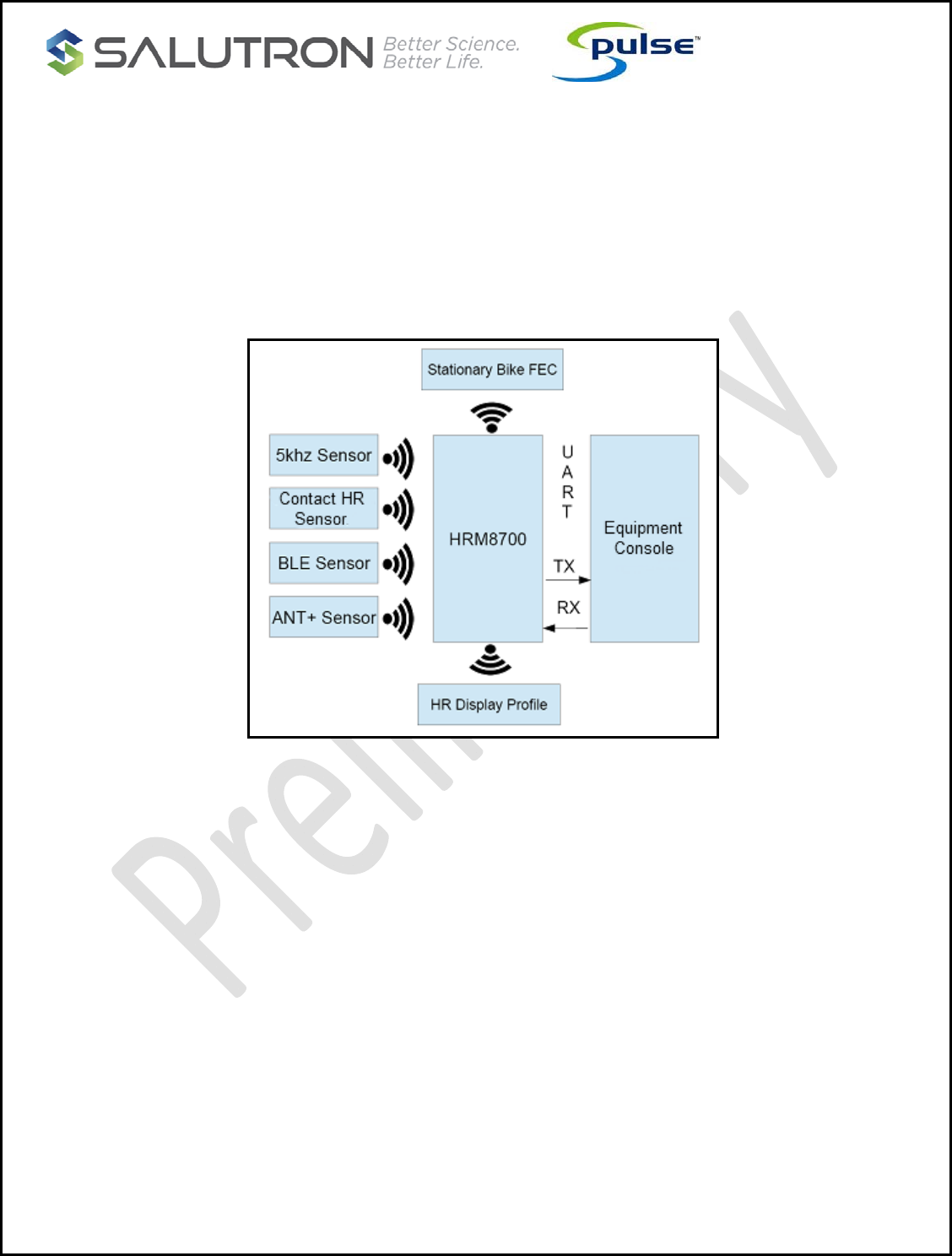
1. UART COMMUNICATION PROTOCOL:
The following section describes the communication protocol between the HRM8700 and Equipment console.
The protocol is intended to provide a reliably link between the HRM8700 and Equipment console. The UART
protocol supports the two way link communication between the two devices.
1.2.Block Diagram
2. OPERATION
2.1. Description
The Equipment console and HRM8700 uses standard UART protocol to transmit and receive custom
packets. The Equipment console controls the HRM8700 operation. The HRM8700 operations are:
Start and stop 5Khz, BLE and ANT+ scanning
Connect and disconnect to a heart rate transmitter using 5khz, BLE and ANT+.
On-demand scanning
Stationary bike FE-C broadcast is activated with user selected ID at the start of workout
HRM display profile is broadcasted with user selected ID at the start of workout
HRM display profile and Stationary bike have the same ID
At the start of a workout session, the Contact Heart rate is enabled and it will stream heart rate
data if active. Contact heart rate will override the wireless data if “contact override” option is
enabled
2.2. UART Specification
Baudrate: 9600 (default), 4800, 2400, 115200
CONFIDENTIAL
Copyright 2017, Salutron, Inc. Revision 0.1 Revision Date: 07/23//17 Page: 10 of 21
Parity: No parity
Flow Control: Disable
2.3. Equipment Assomptions
Upon power up of the equipment device, the HRM8700 should also be powered up. Since the equipment is
controlling the HRM8700, the HRM8700 will be in the idle state or waiting state awaiting command from
the equipment console.
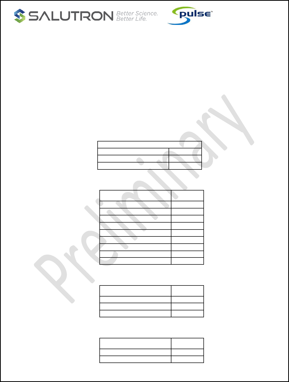
2.4. HRM8700 default configuration
Upon power up, the default settings of the HRM8700 are as follows. The equipment console if needed
could send a command to change any of the default settings at the start of the workout.
• Contact HRM Setting
Contact HRM Setting
Description Setting
Enable Contact Override OFF
Enable RR – Interval OFF
• FE-C
FE-C Setting
Description Setting
Enabled OFF
Hardware Rev 1
Manufacturing ID 1
Model Number 1
Software Revision 1
Supplementary Soft. Revision 0
Serial Number 0
Device ID 3301
• BLE
BLE Setting
Description Setting
Proximity Option 1
Enable OTA OFF
• 5khz HRM
5Khz Setting
Description Setting
Auto Connect OFF

CONFIDENTIAL
Copyright 2017, Salutron, Inc. Revision 0.1 Revision Date: 07/23//17 Page: 11 of 21
2.5. Equipment and HRM8700 Operations
The equipment console will send “workout” command to HRM8700 to wake it up from the idle state to scanning
state. The HRM8700 will start scanning for 5kHz, BLE and ANT+ HR transmitter advertising within its proximity.
The proximity setting is added in the “workout” command send by the console. While in the scanning state, the
Contact heart rate is always active to stream contact HR data to the console.
The HR transmitter ID that are found during scanning state will be sent to the Equipment console. For BLE, the
advertising name and BLE address are sent to the console. A separator key is added in between the advertising
name and the BLE address. See the UART package table for the details of communication protocol. All BLE HR
transmitter IDs send to the console are uniquely identified. This means there are no duplicate for BLE HR
transmitter IDs received by the equipment console.
For ANT+ the advertising ID is sent to the equipment console. There is a possibility of duplication of ANT+ HR
transmitter IDs because of the limitation of ANT+ protocol in providing certain ID information.
For 5kHz, a "5kHz HRM" name is sent. Only one 5kHz HR transmitter is send to equipment console while a
maximum five each of BLE and ANT+ HR transmitter are sent to the equipment console for a maximum of eleven
HR transmitters. Although the console can receive more than eleven devices, the limitation is due to the capacity
of HRM8700 microcontroller. Maximum capacity might change in the future or upon customer request.
After all HR transmitter IDs within the pairing proximity range are sent to the equipment console, the user is
expected to choose what type of HR transmitter to be used during workout. If the user selects the BLE HR
transmitter, the corresponding BLE address is sent back to HRM8700. The BLE address is one of the parameters
for pairing and tracking BLE HR transmitter.
If user selects an ANT+ HR transmitter, the HRM8700 will use the ANT+ advertising name for pairing and
tracking. If there are more than one ANT+ HR transmitter with the same advertising name then there might be a
chance for the user to pair to a wrong HR transmitter. For a 5kHz HR transmitter, the transmitter with the
strongest signal is expected to be paired.
After the HRM8700 successfully pairs with the selected HR transmitter, it starts streaming the heart rate data to
the console. The frequency of heart rate streaming will be dependent upon the kind of connected HR transmitter,
but for 5kHz and Contact HR it would depend upon the heart rate BPM rate.
A special process is implemented if only 5kHz is detected during scanning. By default, the HRM8700 will not wait
for user confirmation, but will directly connect to the 5kHz HR transmitter if it is the only one detected during
scanning. HR data will automatically be sent to the console after connection. However the console has an option
to override it with the “5KHZ disable auto connect” command. In this case the console will wait for user
confirmation.
The Contact mode can be configured as contact override on or off. It also can stream the R-R interval value after
a valid HR is sent to the console. The R-R interval is available in Contact HR mode only if the option is enabled.
The equipment console would need to send a “stop workout” command to disconnect the HRM8700 to the paired
HR transmitter. The HRM8700 will forget that HR transmitter and go to idle state and wait for the next
interaction.

CONFIDENTIAL
Copyright 2017, Salutron, Inc. Revision 0.1 Revision Date: 07/23//17 Page: 12 of 21
2.6. HRM8700 OTA.
For the HRM8700 a new code update can be flashed by using over the air programming. The BLE DFU
feature of the HRM8700 can be triggered using the activation
command
from the console. Once triggered
the HRM8700 function as BLE peripheral and will broadcast “HRM_8700”. Using the Nordic NRF Connect
application installed in the iphone/Android phone and an OAD zip file (released by Salutron), the HRM8700
firmware can be updated. For more information and procedure on how to OTA, please refer to the
HRM8700 OAD procedure document.
CONFIDENTIAL
Copyright 2017, Salutron, Inc. Revision 0.1 Revision Date: 07/23//17 Page: 13 of 21
3. UART COMMUNICATION PROTOCOL PACKETS
3.1. Packets
The uart protocol packets contain data that will be used as an interface between the HRM8700 and the
equipment console. A maximum of twenty four bytes and a minimum of eight bytes are used during UART
communication.
Fletcher checksum reference: https://en.wikipedia.org/wiki/Fletcher%27s_checksum
For 5kHz analog strap, the name to be transmitted will be “5kHz HRM”.
Below is the UART packet:
A response bit when set means the receiver is obliged to response acknowledgement when package is
received from the transmitting UART port
START
COMMAND PACKET LEN CHECK
SUM RESPONSE
BIT CLASS SUB DATAx
Type Size in bytes Description
START COMMAND 1 Start byte
PACKET LEN 1 Number of bytes in a packet
CHECK SUM 2 Fletcher checksum
RESPONSE BIT 1 Response bit
CLASS 1 Packet Class type
SUB CLASS 1 Packet sub-class type
DATA XX Data
3.2. Example of Sending Packets Equipment Console
Usage:
Sending packet name to equipment console
Format:
[Start Command]
[Packet Size]
[Fletcher check sum low byte]
[Fletcher check sum high byte]
[Response bit]
[Class]
[Sub Class]
[Name 1st byte]
[Name … byte]
[Name xth byte]
Packet:
ex. 5Khz advertising name = “5kHz HRM”
[0x0A]
[0x0F]

CONFIDENTIAL
Copyright 2017, Salutron, Inc. Revision 0.1 Revision Date: 07/23//17 Page: 14 of 21
[0xYY]
[0xZZ]
[0x0C]
[0x00]
[0x01]
[0x35]
[0x6B]
[0x48]
[0x7A]
[0x20]
[0x48]
[0x52]
[0x4D]
3.3. Example of Sending Packet to HRM8700
Usage:
Sending selected packet name to HRM8700
Format:
[Start Command]
[Packet Size]
[Fletcher check sum low byte]
[Fletcher check sum high byte]
[Response bit]
[Class]
[Sub Class]
[Name 1st byte]
[Name … byte]
[Name xth byte]
Packet:
ex. 5Khz advertising name = “5kHz HRM”
[0x0B]
[0x0F]
[0xYY]
[0xZZ]
[0x00]
[0x1C]
[0x01]
[0x35]
[0x6B]
[0x48]
[0x7A]
[0x20]
[0x48]
[0x52]
[0x4D]

CONFIDENTIAL
Copyright 2017, Salutron, Inc. Revision 0.1 Revision Date: 07/23//17 Page: 15 of 21
Appendix A : Grounding and ESD Recommendations
Overview
For accuracy and performance, the HRM8700 wireless receiver and heart rate monitor (HRM) combo must
be properly grounded. Improper grounding introduces unwanted noise that can overwhelm the ECG signals
and compromise the signal-to-noise ratio. Improper grounding can also leave the system vulnerable to
problems from electrostatic discharge (ESD), which can cause the console to reset. In order to provide a
stable ground for the HRM8700 and to protect from ESD, the ground needs to be free of noise and have
very low impedance.
This application note provides grounding and ESD recommendations based on common installations of the
HRM8700. The recommended method provides a dedicated ground for this board.
The above solution requires as a prerequisite a good regulated power supply. This is because when the
ESD current causes transient on the ground wire, the power supply can regulate and absorb the energy to
a certain extent so that it is not propagated to the rest of the system to cause resets.
If flat ribbon cable is used as the inter-connect between HRM and Client console, multiple circuits are
required for +5V and Return to ensure low impedance.
It is also a good practice to use a reliable supervisory integrated circuit for power up and power down
management to avoid undesired resets to the microcomputers when ESD occurs.
For treadmills, the motor drive design is also critical to ensure an electrically quiet system to meet FCC
Class A and Class B compliance. The inductive load creates radiated noise with wide band characteristics
that will compromise heart rate performance in acquisition time. (See footnote of ECG Measurement on
page 7)
CONFIDENTIAL
Copyright 2017, Salutron, Inc. Revision 0.1 Revision Date: 07/23//17 Page: 16 of 21
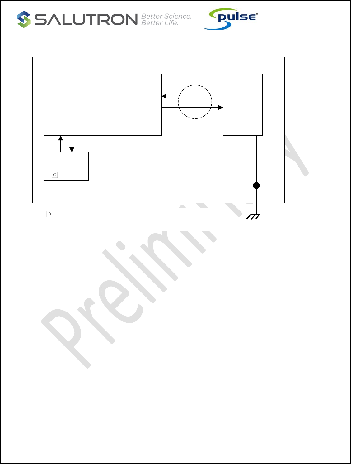
Wire Return
Figure A1: Wire return grounding recommendation
A wire return is an effective solution for grounding and ESD protection. However, the impedance in the
wire can limit the effectiveness in conducting ESD current. Therefore, it is recommended that a return wire
of 16 gauge is used. The wire should be made as short as possible, not to exceed 12 inches.
In Figure A1, a return wire is attached directly to HRM at HD1 hole. Because of unwanted noise, do not tie
the return wire to the ground (indicated RTN above) from the power supply but to earth ground directly.
The return wire connected to the earth ground can be ordered pre-assembled with the HRM8700. See the
“Order Information“ section for order details.
Console Power
Supply
Plastic Back Panel
HRM
+5V RTN Interconnect
Earth Ground
Attach return wire (attached to HRM at HD1)
directly to earth ground.
Vcc
RTN
Return wire

CONFIDENTIAL
Copyright 2017, Salutron, Inc. Revision 0.1 Revision Date: 07/23//17 Page: 17 of 21
ESD Protection
The independent return wire described earlier also serves as an ESD return path when electrostatic
discharge occurs. The high voltage protection circuit in the HRM will cause the discharging current to pass
through this independent ground path. Therefore, the console is less likely to latch up due to the
incomplete reset caused by unpredictable ESD current.
The return ground does not conduct current unless ESD occurs. However, when ESD occurs, the ground
must have low impedance to discharge the ESD energy. To ensure low impedance, a 16 gauge copper
wire is recommended for ESD protection. The length of the wire should not be made longer than 12
inches. The wire should be bolted to the closest spot in the equipment where a reliable chassis ground is
available.
A dedicated ground plane in the console PCB may help to reduce the chance of latch-up when ESD fires.
A good supervisory IC is highly recommended to reduce possibilities of resetting the console, too.
The HRM8700 Wireless Receiver and HRM product was tested by HAEFELY PESD3010 system that is
certified for IEC 61000-4-2 level 4 for both air and contact ESD tests.
CONFIDENTIAL
Copyright 2017, Salutron, Inc. Revision 0.1 Revision Date: 07/23//17 Page: 18 of 21
Appendix B: HRM8700 Placement Guideline
The electrical noise generates from the machine could affect the reception range of 5KHZ wireless
receiver. It is better to avoid any noise frequency near 5KHZ or harmonics get near the module.
Although not all electrical noise can be avoided, the following sources could contribute to the
interference. It is recommended to position the HR wireless module as far from these sources as
possible.
LED display
Electrical fan
Audio speaker
Magnetic field
Piezo buzzer/beeper
Magnetic brake (Bike)
External/ internal CD player
Excessive ripple noise on power supply
Switching power supply
Motor controller
Sound or noise source in audio band (20HZ~20KHZ)
Cell phone
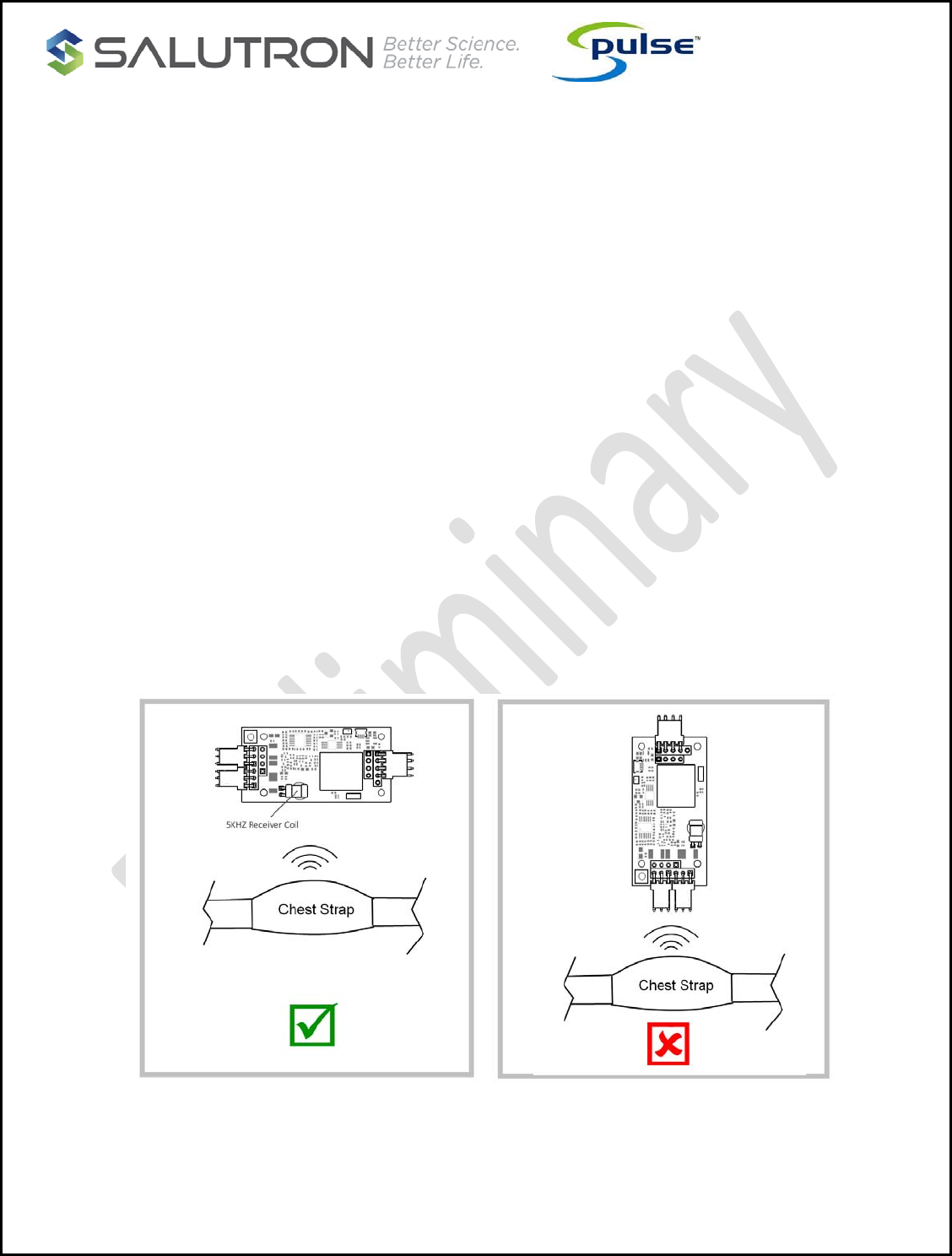
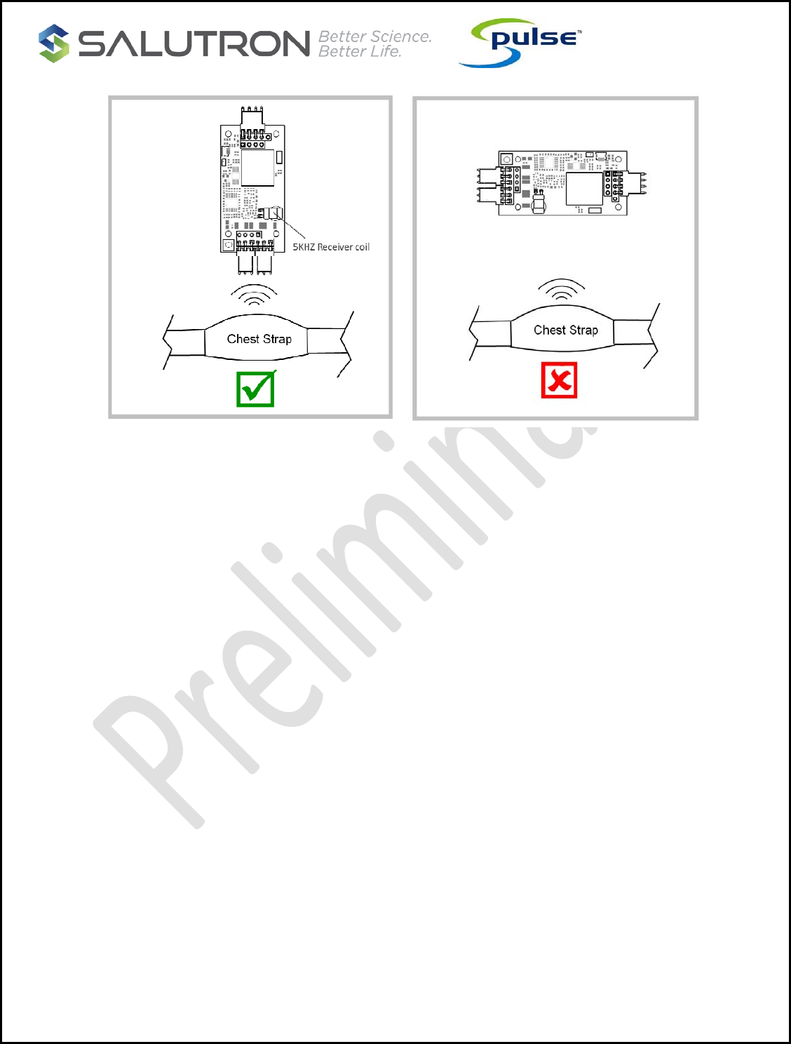
An incorrect wireless coil orientation placement will affect the range. The orientation of the receiving
coil on the HRM wireless module should be in horizontal or parallel with the transmitter’s coil to obtain
the optimal performance.
CONFIDENTIAL
Copyright 2017, Salutron, Inc. Revision 0.1 Revision Date: 07/23//17 Page: 19 of 21
The ideal placement location of the HR wireless module would be at the center, toward the front that is
closer to the user, and away from the noise sources.
In case the wireless module has to place off to the left or right side from the center of the console,
then try to keep the offset distance within 12 inches (30cm) or less, otherwiseThe reception distance of
the HRM will be shorten if it is placed too far off from the center.

CONFIDENTIAL
Order Information
Salutron’s commitment to customer satisfaction is the driving force behind our product
offerings. Contact us to discuss any specific connector options, preloaded features, and
specific application information that you may need.
Life Support Policy
Salutron’s products are not authorized for use as critical components in life support devices or
systems.
Contact Information
SALUTRON, INC.
8371 Central Avenue, Unit A
Newark, CA 94560
Office: 510-795-2876
http://www.salutron.com
Hardware Revision: PCB8740-4L Rev B
Software Revision: V3302C
Frequency Band(s):
Bluetooth 4.2+BLE:
Frequency Bands:2402-2480 MHz
ANT+:
Frequency Bands:2457 MHz
Transmit Power Range(s):
Bluetooth 4.2+BLE:
Max power:-6.88 dBm
ANT+:
Max power:-3.60 dBm
Modulation Type(s):
Bluetooth 4.2+BLE:
Modulation Mode: GFSK
ANT+:
Modulation Mode: GFSK
Antenna type(s) and Gain(s):
BT&ANT+: Ceramic Antenna, Antenna gain:0 dBi

CE Maintenance
1.EUT Operating temperature range: -10° C to 40° C .
2. Power Rating:
3.The device complies with RF specifications when the device used less
than 20cm from your body.
Declaration of Conformity
Salutron, Inc hereby declares that this Heart rate module is in
compliance with the essential requirements and other relevant provisions
of Directive 2014/53/EU. In accordance with Article 10(2) and Article
10(10),This product is allowed to be used in all EU member states.
FCC Statement
This device complies with part 15 of the FCC Rules. Operation is subject to the following two
conditions:
(1) This device may not cause harmful interference, and
(2) this device must accept
any interference received, including interference that may cause undesired operation.
Any Changes or modifications not expressly approved by the party responsible for compliance
could void the user's authority to operate the equipment.
If the FCC identification number is not visible when the module is installed inside another device,
then the outside of the device into which the module is installed must also display a label
referring to the enclosed module. This exterior label can use wording such as the following:
“Contains Transmitter Module FCC ID: N7P-HRM8700 Or Contains FCC ID: N7P-HRM8700”
When the module is installed inside another device, the user manual of the host must contain
below warning statements;
1. This device complies with Part 15 of the FCC Rules. Operation is subject to the following two
conditions:
(1) This device may not cause harmful interference.
(2) This device must accept any interference received, including interference that may cause
undesired operation.
2. Changes or modifications not expressly approved by the party responsible for compliance
could void the user's authority to operate the equipment.
The devices must be installed and used in strict accordance with the manufacturer's instructions
as described in the user documentation that comes with the product.
Any company of the host device which install this modular with Single modular approval should
perform the test of radiated emission and spurious emission according to FCC part 15C : 15.247
and 15.209 requirement, Only if the test result comply with FCC part 15C : 15.247 and 15.209
requirement,then the host can be sold legally.
The device has been evaluated to meet general RF exposure requirement. The device can be
used in portable exposure condition without restriction.
IC Warning
This device complies with Industry Canada licence-exempt RSS standard(s). Operation is subject
to the following two conditions:
(1) This device may not cause interference, and
(2) This device must accept any interference, including interference that may cause undesired
operation of the device.
Le présent appareil est conforme aux CNR d'Industrie Canada applicables aux appareils radio
exempts de licence. L'exploitation est autorisée aux deux conditions suivantes: (1) l'appareil ne
doit pas produire de brouillage, et (2) l'utilisateur de l'appareil doit accepter tout brouillage
radioélectrique subi, même si le brouillage est susceptible d'en compromettre le fonctionnement
The device has been evaluated to meet general RF exposure requirement. The device can be
used in portable exposure condition without restriction.
Le dispositif a été conçu pour rencontrer le général RF. Le dispositif peut être utilisé dans des
conditions de détention sans effet.
For a host manufacture's using a certified modular, if (1) the module's IC number is not visible
when installed in the host, or (2) if the host is marketed so that end users do not have
straightforward commonly used methods for access to remove the module so that the IC number
of the module is visible; then an additional permanent label referring to the enclosed module:
"Contains Transmitter Module IC: " 10274A-HRM8700 " or "Contains IC: 10274A-HRM8700" must
be used.
Pour un hôte, on utilise un modular, si (1) le numéro de module est non visible
Quand on est installé dans le serveur, or (2) si le propriétaire est commercialisé
Straightforward commonly used for the access to remove travail so that the number IC en vue
Le module est visible;Ensuite, le label permanent a été attribué au module:
"Contient le Module IC:" 10274A-HRM8700" ou "le contenu IC: 10274A-HRM8700" doit être
utilisé.