Samsung Electro Mechanics ESL-BP102 Gen3 Gateway User Manual
Samsung Electro Mechanics Gen3 Gateway
User manual
1
Samsung Electro-Mechanics
ESEL User Manual
(SLG-BP102)

2
Document Summary
Author: WS3 G, CDS Division, Samsung Electro-Mechanics
Distributor: Samsung Electro-Mechanics
Tel.: 031-300-4913
www.sem.samsung.com
Editor Information
- Tel.: +82-31-300-4913
- Address: 314, Maetan3-Dong, Yeongtong-Gu, Suwon, Gyunggi-Do, Korea 443-743
Copyright Notification
Samsung Electro-Mechanics Co., Ltd.
Copyright @2009 SEMCO INC.
All trademarks used are properties of their respective owners.
The content of this document is subject to change without prior notice.
The content of this document is intellectual property of Samsung Electro-Mechanics.
This document may not be reproduced or published without prior consent from Samsung Electro-Mechanics.
No part may be reproduced except as authorized by written permission.
The copyright and the foregoing restriction extend to reproduction in all media.
© 2008, SEMCO INC.
All rights reserved.

3
Revision History
Rev. Date Remark
1.0 22.04.2014 First Edition.

4
Contents
1. Precautions .............................................................................................................................. 5
2. Overview ................................................................................................................................... 6
3. Product Specifications ...................................................................................................... 7
3.1 General Specifications ..................................................................... 7
3.1.1 Gateway
3.2 RF Specifications .............................................................................. 8
3.2.1 Gateway
4. Product Description ........................................................................................................... 9
4.1 Exteior ............................................................................................... 9
4.1.1 Gateway
5. Product Installation .......................................................................................................... 10
5.1 Gateway
....................................................................................... 10

5
1. Precautions
“This RF device operates on the 2.4GHz frequency band and can produce radio
interference. The device, therefore, may not be used for applications where safety of human
lives is concerned.”
1) Usage Environment
Take extra caution when using this RF device in the vicinity of other electronic devices and
appliances. Most electronic devices and appliances use electromagnetic waves. Electromagnetic
waves emitted by this RF device can affect other electronic devices and appliances.
If using the device in an explosion hazard area, follow all safety regulations, instructions, and
signals.
2) Storage and Use
Moisture and liquids can damage internal parts and circuit boards if allowed to enter into the device
itself.
Do not place or store the product on a sloped surface. The product may slide and fall off the surface
and damage.
Use the product in temperatures ranging from 0℃ to +60℃. Parts and circuits may damage if
used or stored under temperature extremes.
Avoid areas with strong magnetism or subject to magnetism.
Contact between the device and a magnetic object can lead to malfunctions.
Do not place the product near heat-producing kitchen appliances like a stove or a microwave or
in the vicinity of highly pressurized containers.
External impact to the product, such as from being dropped, can damage the screen.
Twisting and bending the product can damage the exterior casing and the internal components.
6
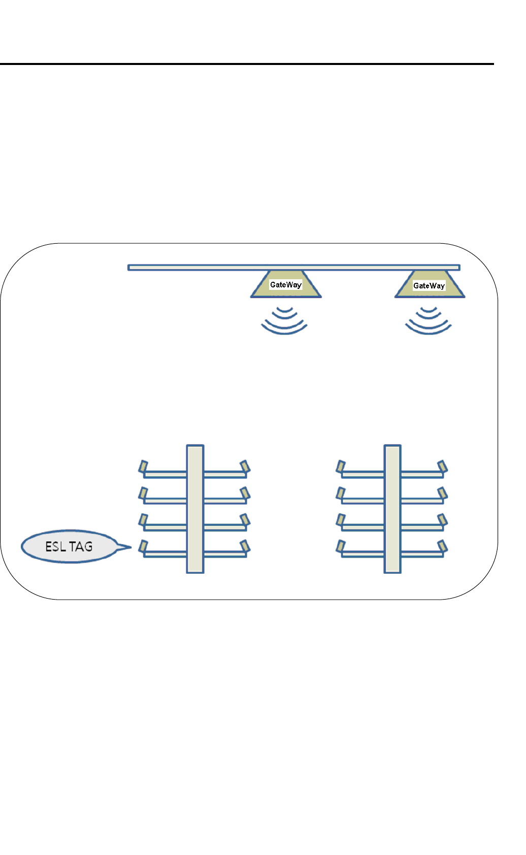
2. Overview
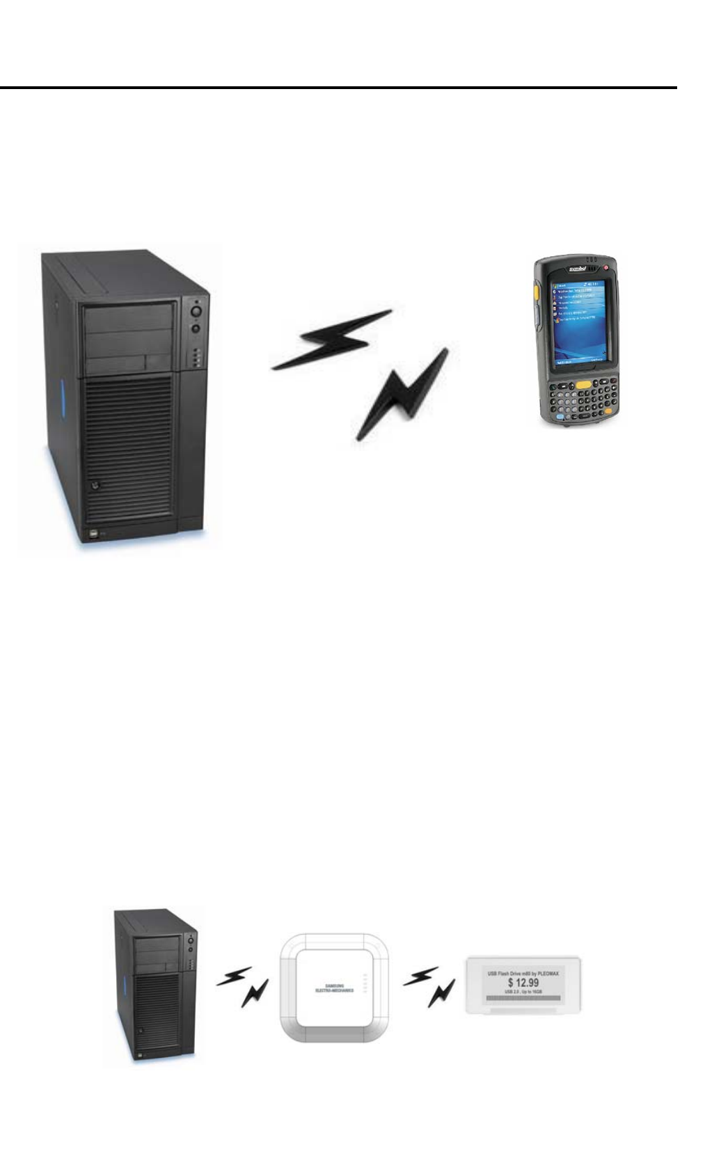
Gateway make up a system the electronically displays price and other product information that
are traditionally shown printed or written on paper in places like the supermarket.
Here, S-Label Gateway receives product price updates from the server and uploads the new
data to the applicable electronic tags (S-Label Tag), changing the displayed price information.
<Diagram 1> S-Label System
7
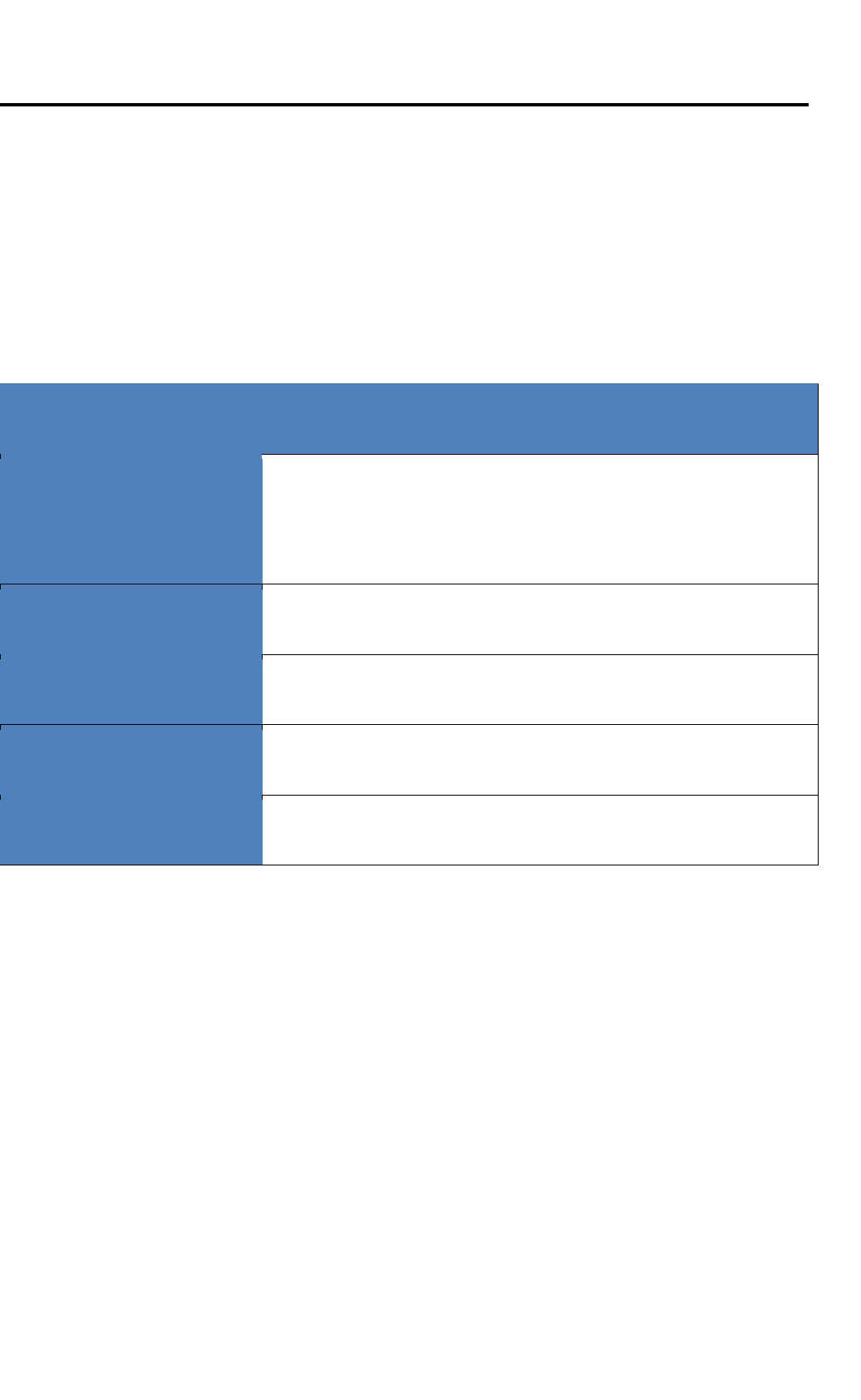
3. Product Specifications
3.1 General Specifications
3.1.1. Gateway
General
Communication
Ethernet (10/100Mbps)
Zigbee RF(based on IEEE 802.15.4)
Dimension (W*H*D) 215 * 215 * 44 (mm)
Weight (g) 1,385g
Enclosure Plastic (ABS)
Power DC Adaptor(5V,2A) or PoE (Power over Ethernet(IEEE802.3af))
Caution : DC Power Supply or PoE(Power over Ethernet) using one

8
3. 2 RF Specifications
3.2.1 Gateway
Category Specification Note
Antenna Type Internal Antenna 2ea
Transmit Frequency 2405MHz ~ 2480MHz
Receive Frequency 2405MHz ~ 2480MHz
Antenna gain SAC0 : 0.99dBi
SAC3 : 1.57dBi
Modulation O-QPSK
Channels 16ch
Power █ DC Adapter (5V, 2A)
█ PoE (Power over Ethernet (IEEE802.3af))
1) Input Voltage Range :36~57VDC
2) Nominal Input Voltage : 48VDC
2) Output Voltage : 5VDC±3%
9
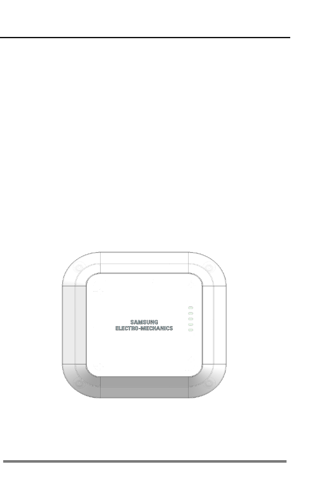
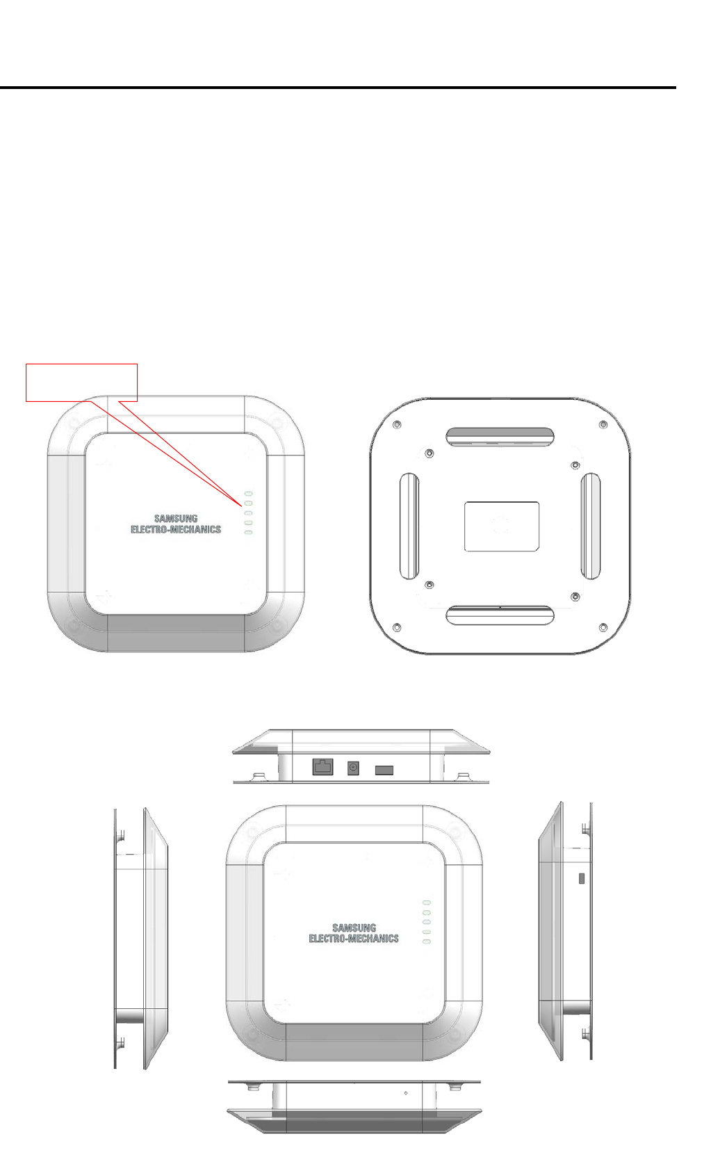
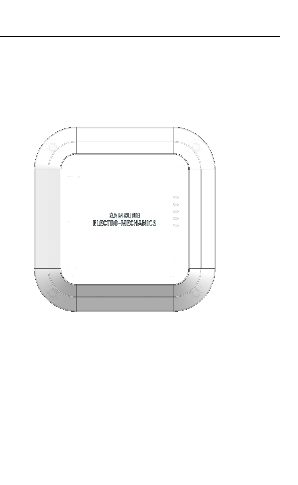
4. Product Description
4-1 Exterior
4.1.1 Gateway
<top> <bottom >
Status LED
10
5. Product Installation
5-1 Gateway
- Components (includes installation accessories – adapter, bracket, screws)
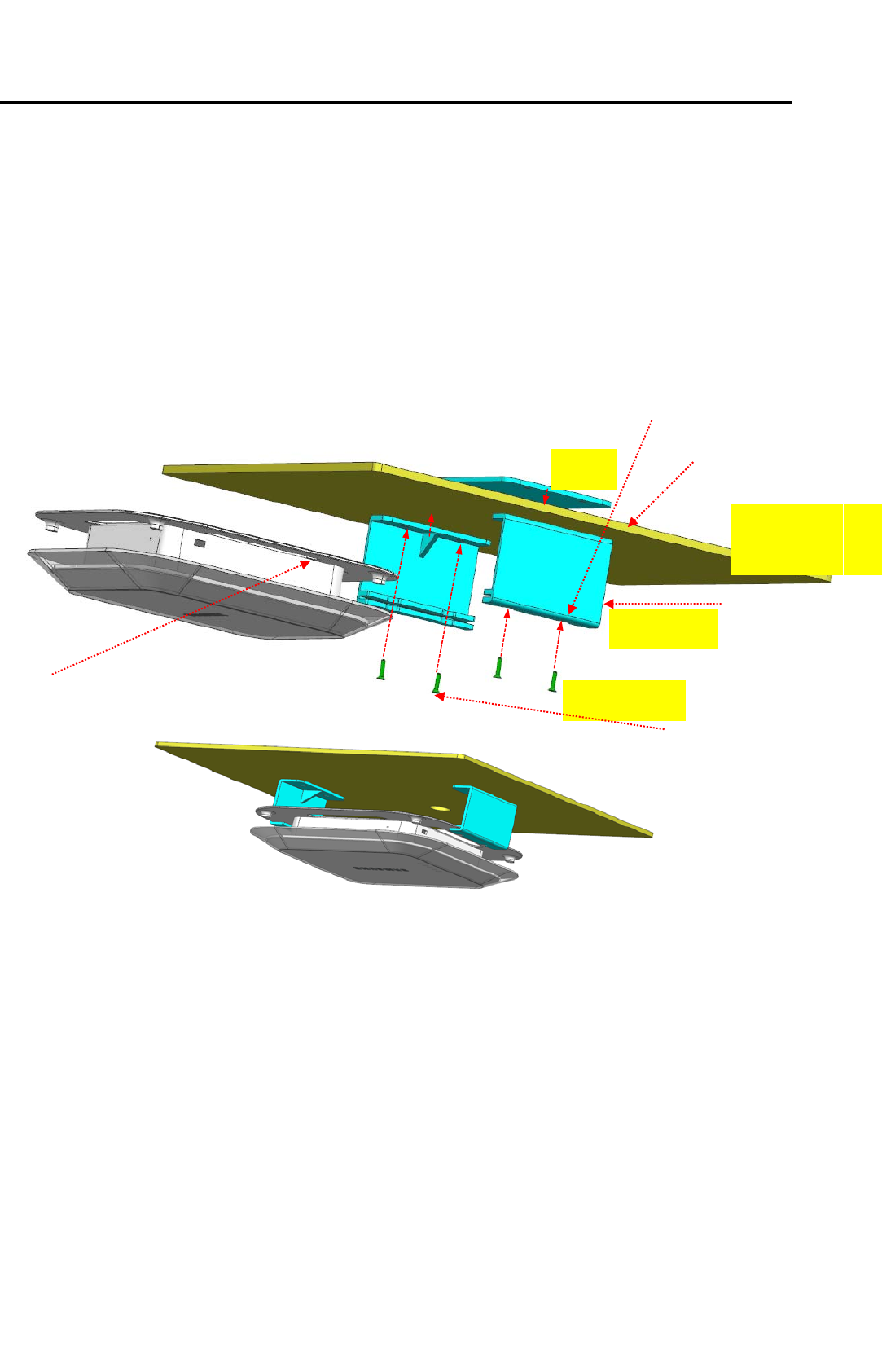
Installation
a) Drill 4 holes on the wall or ceiling to align with mounting Plates (1). Refer to the attached
diagram.
b) Drill two Ф10 holes on the wall or ceiling for SMPS Adapter and Ethernet Cable.(2) Refer to
the attached diagram.
c) Align the mounting bracket#2 holes to the holes drilled through the wall or ceiling from step a)
and temporarily secure the bracket in place. (3)
d) Use Screws to completely secure the mounting bracket and Wall or Ceiling. (4)
e) Sliding gateway to mounting bracket#2 (5)
Gypsum
board
Plate
Screw (4ea)
Bracket#2
1) Mounting Plate
2) Drilling hole
for ADT,LAN cable
3) Attach Bracket#2
4) Screw
5) Sliding Gateway
11
f) SMPS Adapter and Ethernet Cable through the two Ф10 holes made from step b).
Operation Check
< Connect Ethernet Cable with PoE or Connect SMPS adapter and Ethernet cable first . >
1) Power : Always ON after connecting to Ethernet Cable with PoE or SMPS adapter
2) Ethernet : ON if Ethernet link is connected
- Check every 1sec whether Ethernet link is connected.
3) Data : ON when data duration
4) Wakeup : ON when Wakeup duration
5) SIL
4) Wakeup
3) DATA
2) Ethernet
1) POWER
12
5) SIL : Blink (duration 1sec) if Server interface layer is operated.
- Check operation of Server interface layer
.
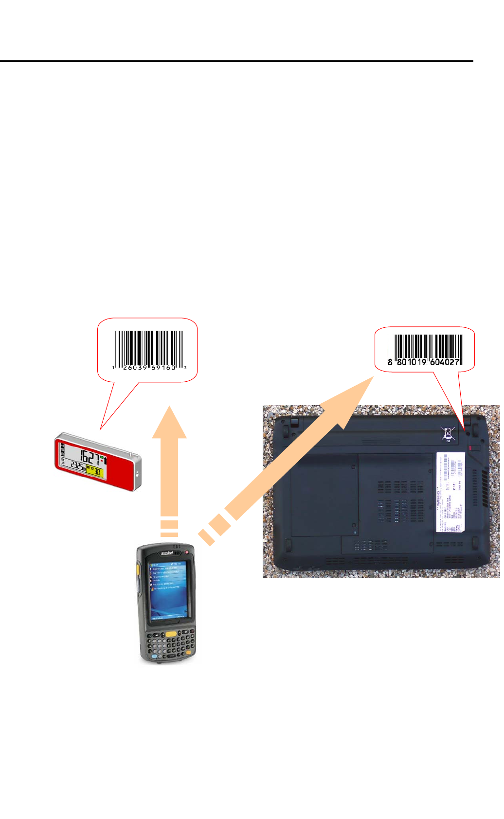
Installation
a) Map product information and tag IDs.
Each tag has a unique 1) MAC Address that serves as the tag’s ID.
Map 1) MAC Addresses of the tags and 2) barcodes of the products.
Using a PDA featuring Win CE 5.0 or higher as the operating system and a barcode scanner,
scan the tag’s 1) MAC Address and then the product’s barcode to map.
+
(1) MAC Address (2) Product
Barcode
(3) Industrial PDA
13
b) Register product and tag mapping information.
Using the PDA’s WLAN feature, register mapping data with the 4) Server.
c) Attach a back rail to the shelf (secure using double-sided tape or screws).
d) Attach end and middle caps to the middle rail.
e) Take a tag that has been mapped from step a) and insert to the middle rail from step d). Here,
make sure to align the tag and the rail grooves properly.
f) Slide in the middle rail to the fixed back rail.
g) Products information on Tags such as price will be updated from the server regularly via
gateway
(4) Server
WARNING : This equipment may generate or use radio frequency energy. Changes or
modifications to this equipment may cause harmful interference unless the modifications are
expressly approved in the instruction manual. The user could lose the authority to operate this
equipment if an unauthorized change or modification is made.
This device complies with part 15 of the FCC Rules. Operation is subject to the following two
conditions: (1) This device may not cause harmful interference, and (2) this device must accept
any interference received, Including interference that may cause undesired operation.
NOTE : This equipment has been tested and found to comply with the limits for a Class B digital
device, pursuant to part 15 of the FCC Rules. These limits are designed to provide reasonable
protection against harmful interference in a residential installation This equipment generates, uses
and can radiate radio frequency energy and, if not installed and used in accordance with the
instructions, may cause harmful interference to radio communications, However, there is no
guarantee that interference will not occur in a particular installation. If this equipment does cause
harmful interference to radio or television reception, which can be determined by turning the
equipment off and on, the user is encouraged to try to correct the interference by one or more of
the following measures:
- Reorient or relocate the receiving antenna.
- Increase the separation between the equipment and receiver.
- Connect the equipment into an outlet on a circuit different from that to which the receiver is
connected.
- Consult the dealer or an experienced radio/TV technician for help.
Caution
This device complies with FCC radiation exposure limits for an uncontrolled environment.
Avoid operating this device at a distance less than 20cm from the user.