Samsung Electro Mechanics SCF-V01 3G CDMA PCIe Full Mini Card User Manual SCF V01 120618x
Samsung Electro Mechanics 3G CDMA PCIe Full Mini Card SCF V01 120618x
UserManual.wiki
>
Samsung Electro Mechanics
>
SCF V01 User Manual
user manual
Navigation menu
Upload a User Manual
Namespaces
Wiki Guide
HTML
PDF
Info
Views
User Manual
Discussion / Help
Navigation
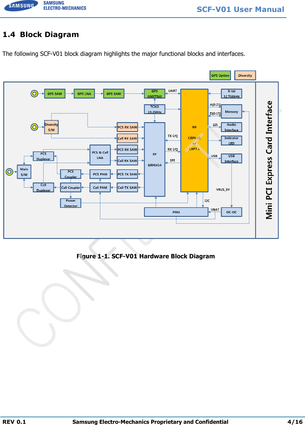

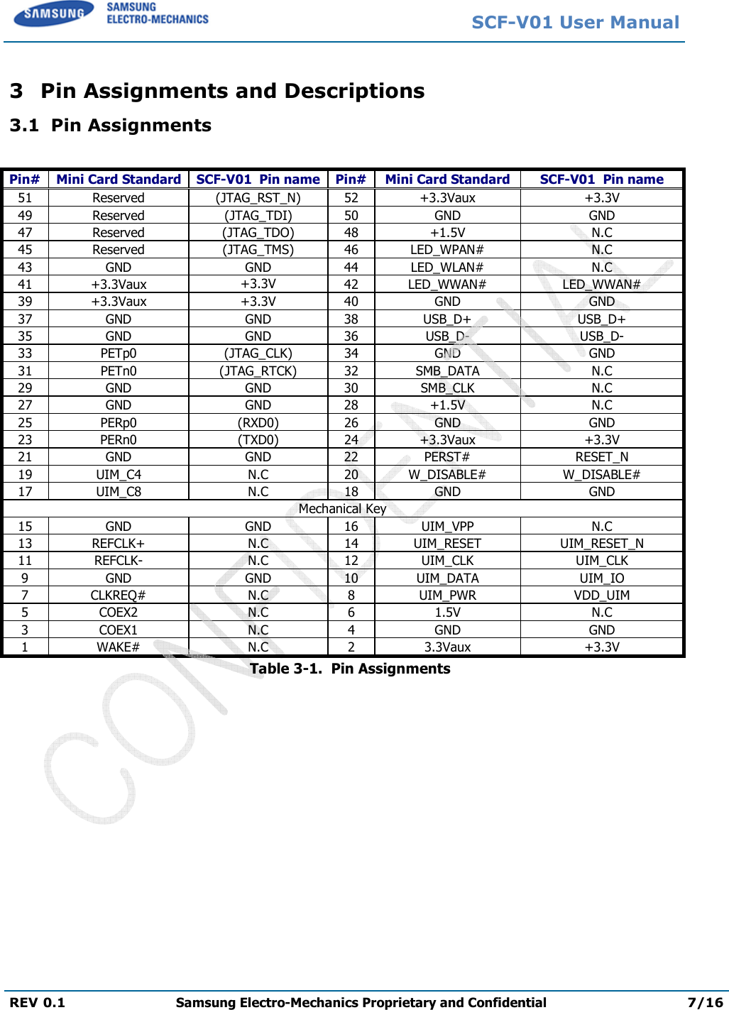
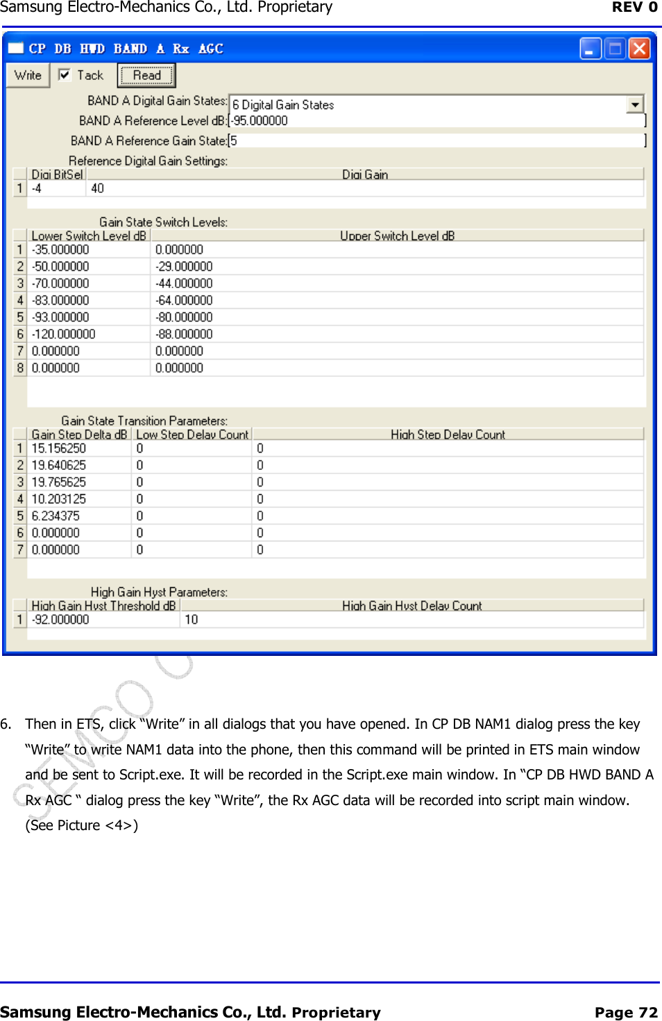
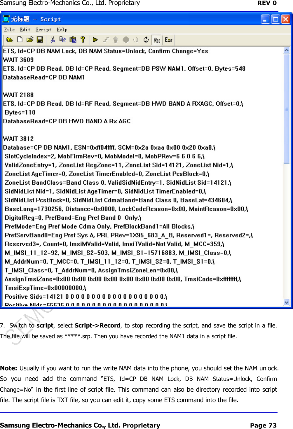
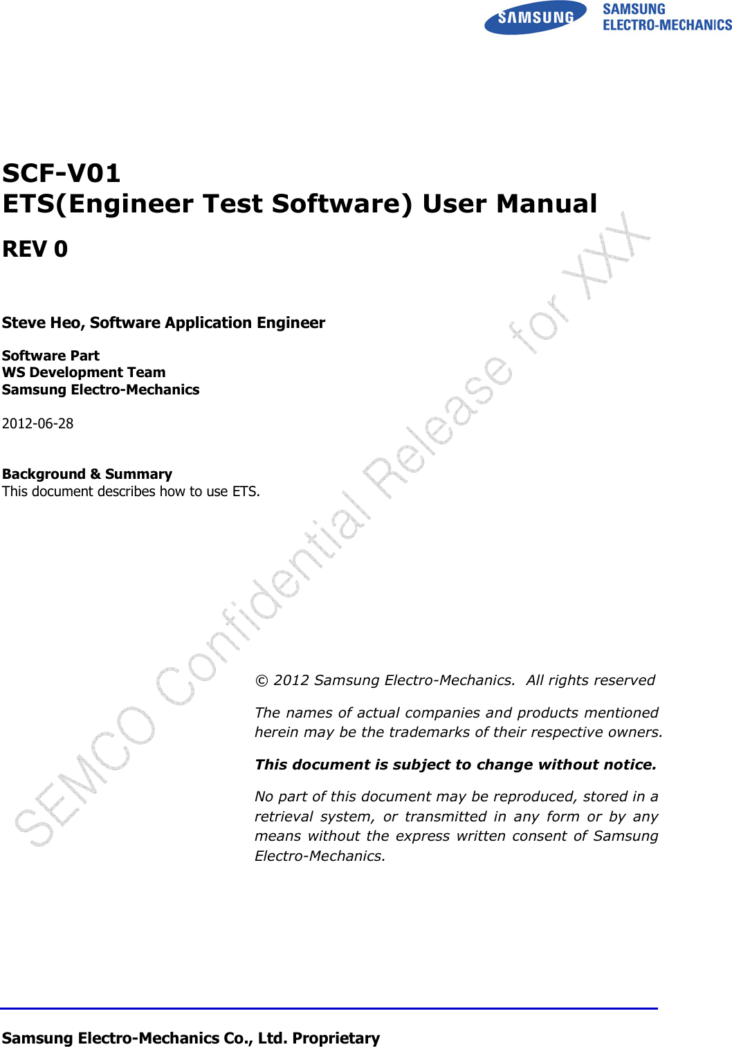
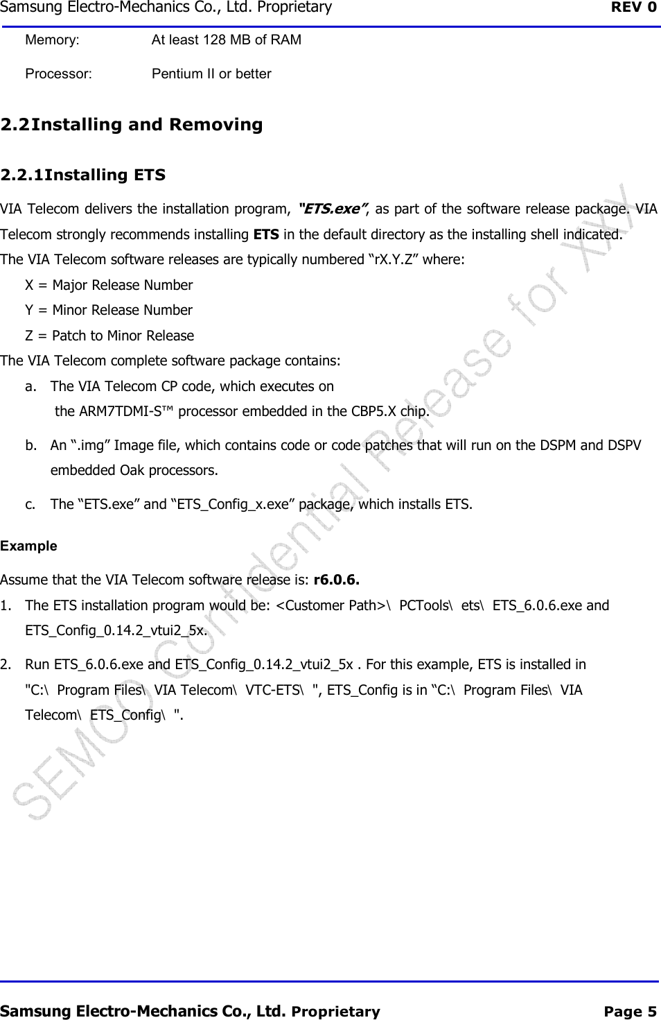
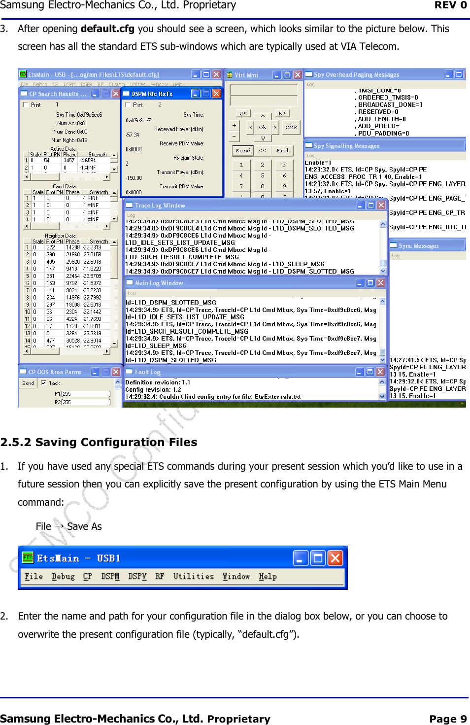
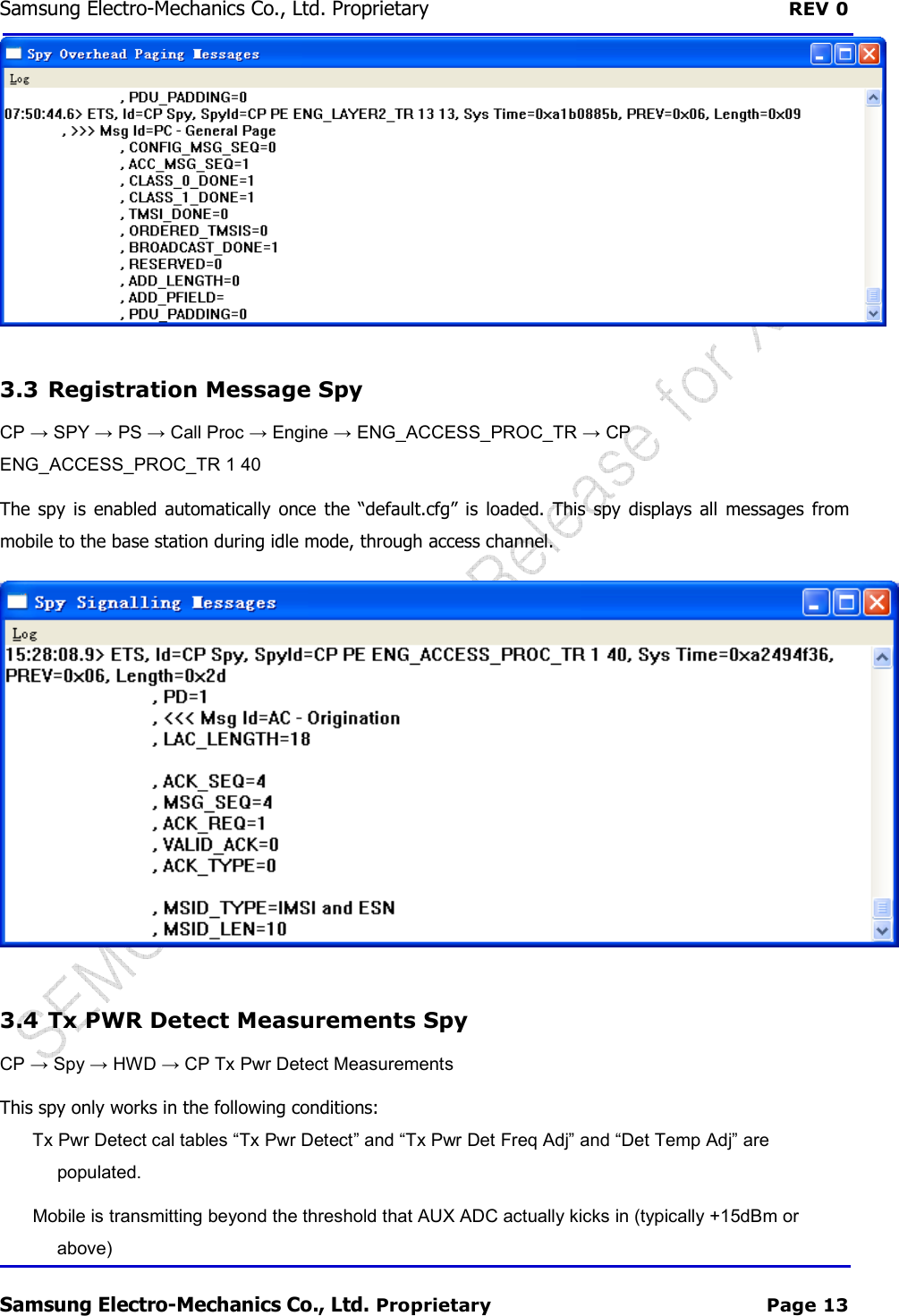
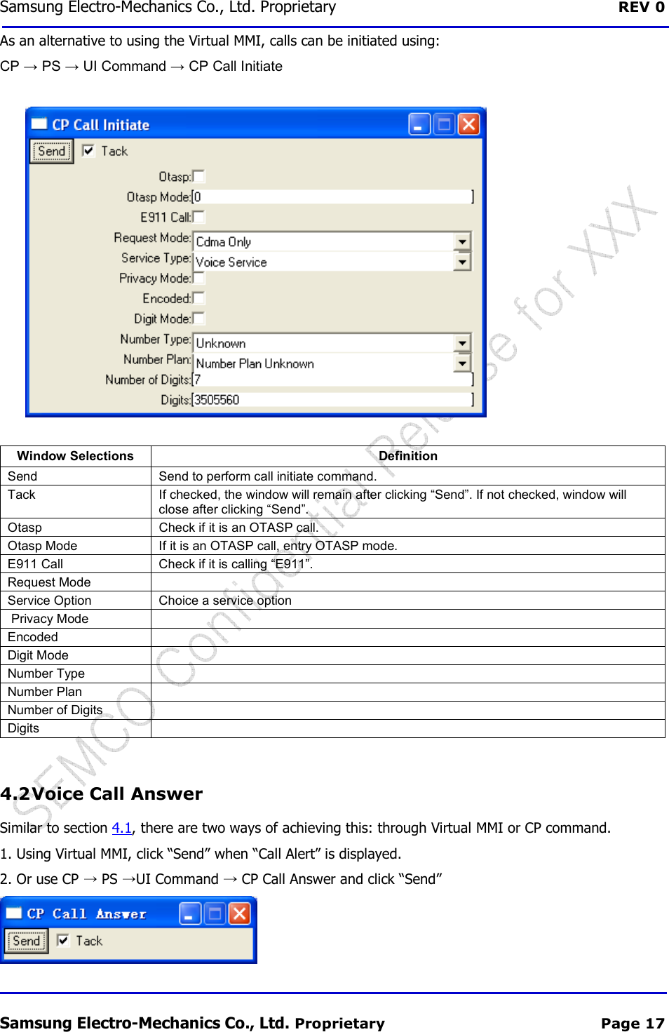
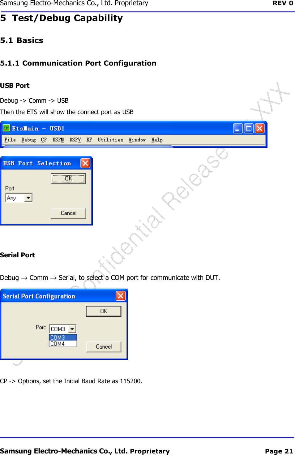
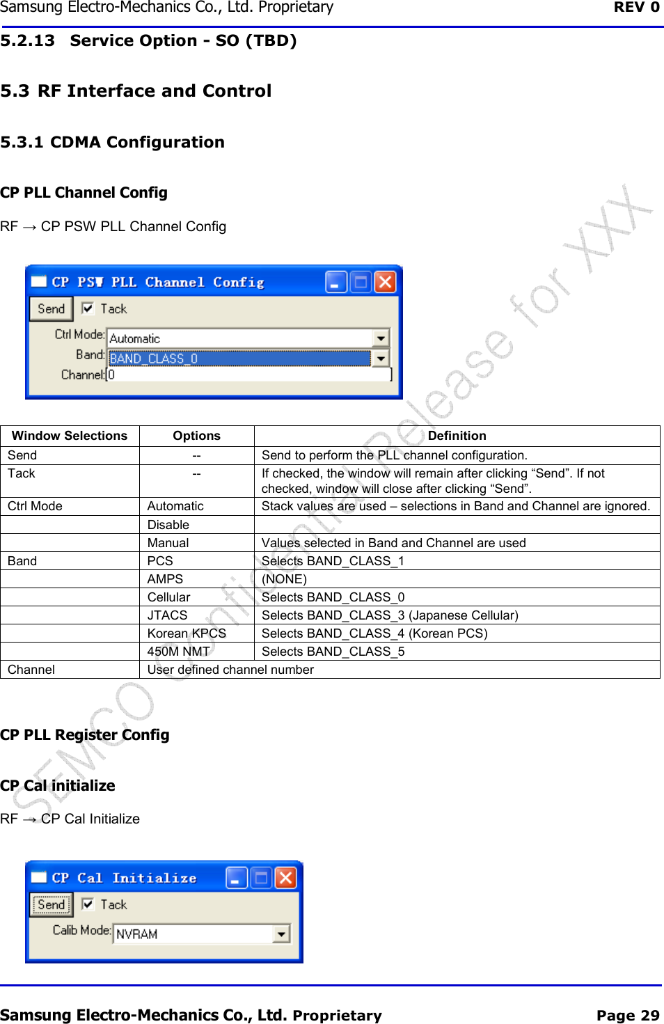
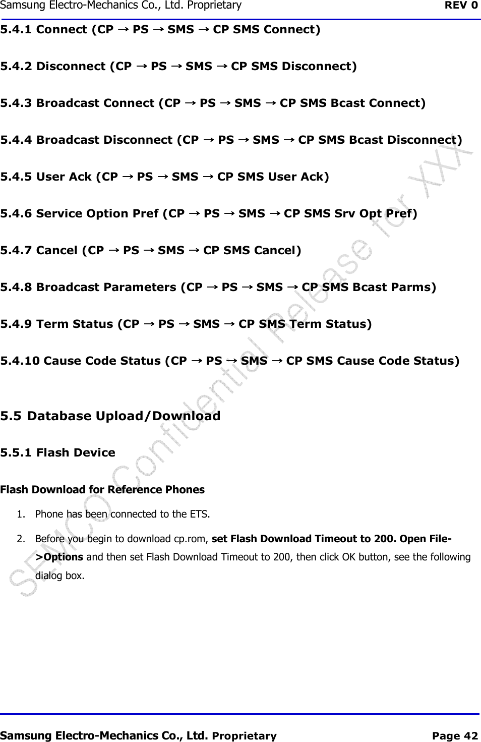
![REV 0.1 Samsung Electro 3.2 Pin Description Pin# Signal Name Type JTAG Interface 33 JTAG_CLK I 47 JTAG_TDO O 45 JTAG_TMS I 49 JTAG_TDI I 51 JTAG_RST_N I 31 JTAG_RTCK O UART Interface 23 TXD0 O 25 RXD0 I USB Interface 38 USB_D- IO 36 USB_D+ IO UIM Interface 10 UIM_IO IO 12 UIM_CLK O 14 UIM_RST_N O GPIOs and Miscellaneous 22 PERST# I 20 W_DISABLE# I 42 LED_WWAN# O Power Supplies 41 +3.3V I 39 +3.3V I 52 +3.3V I 24 +3.3V I 8 VDD_UIM O 2 +3.3V I Ground 43 GND - 37 GND - 35 GND - 29 GND - 27 GND - 21 GND - 15 GND - 9 GND - 50 GND - 40 GND - SCF-V01 Samsung Electro-Mechanics Proprietary and Confidential Connection to IC Pin Power Domain Description CP_TCK (N.C) JTAG Clock CP_TDO (N.C) Data Out CP_TMS (N.C) Mode SelectCP_TDI (N.C) Data In CP_TRST_N (N.C) JTAG Reset CP_RTCK (N.C) JTAG Return Clock CP_UART0_OUT (N.C) UART0 data outCP_UART0_IN (N.C) UART0 data in USB_DMN Inverted USB transceiver data USB_DPS Non-inverted USB transceiver data UIM_IO UIM data input-output UIM_CLK UIM clock signal UIM_RSTN UIM reset signal PM Reset Functional Reset GPIO[01] RF Disable, Active low signal GPIO[06] Status indicator via LED device, Active low signal 3.3V Source 3.3V Source 3.3V Source 3.3V Source UIM power output 3.3V Source Ground Ground Ground Ground Ground - Ground - Ground - Ground - Ground - Ground V01 User Manual Proprietary and Confidential 8/16 t JTAG Return Clock data out data in Inverted USB transceiver data inverted USB transceiver data output , Active low signal Status indicator via LED device, Active low signal UIM power output](https://usermanual.wiki/Samsung-Electro-Mechanics/SCF-V01/User-Guide-1732672-Page-8.png)
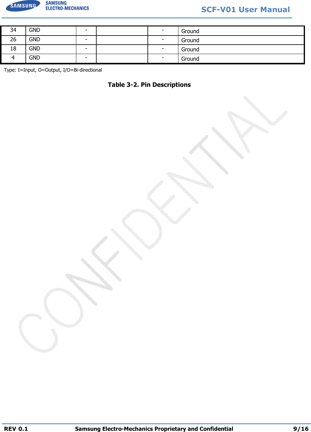
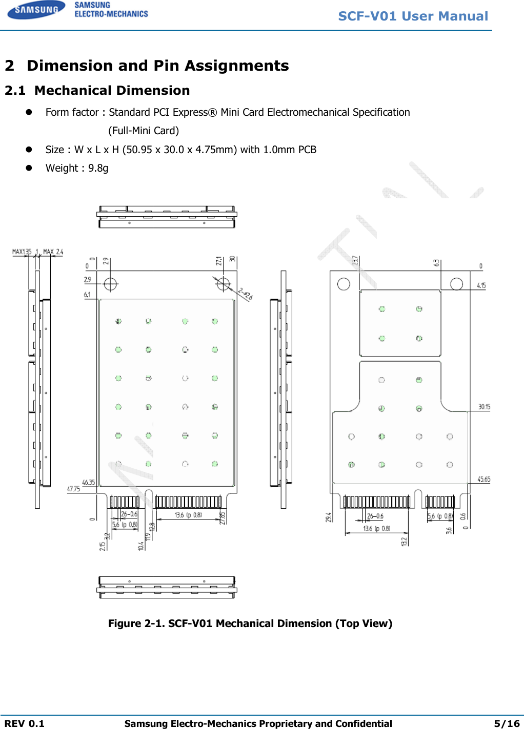
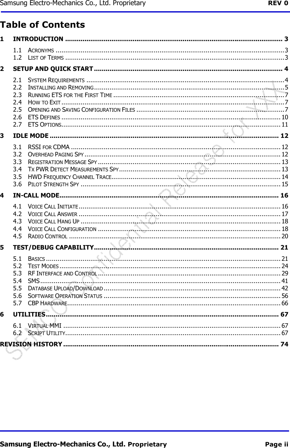
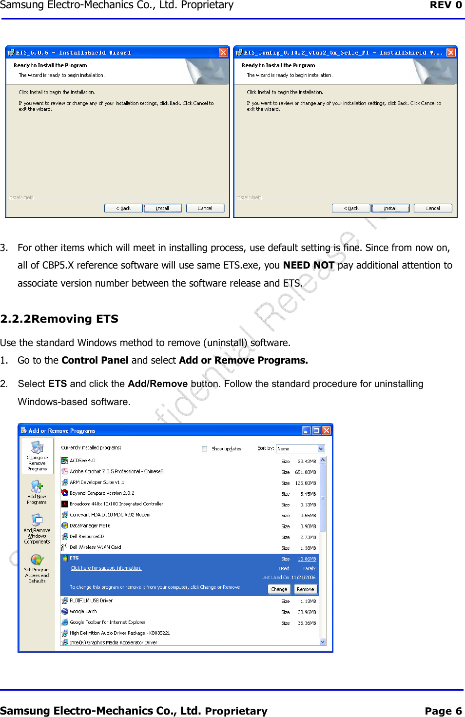
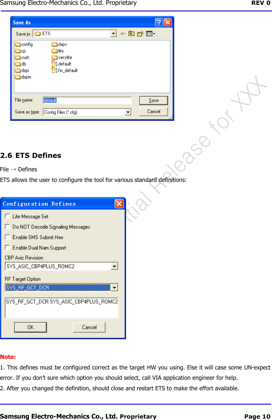
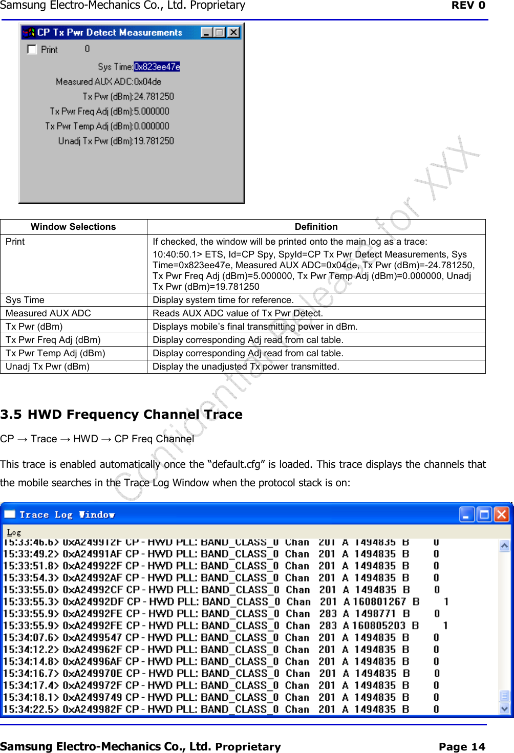
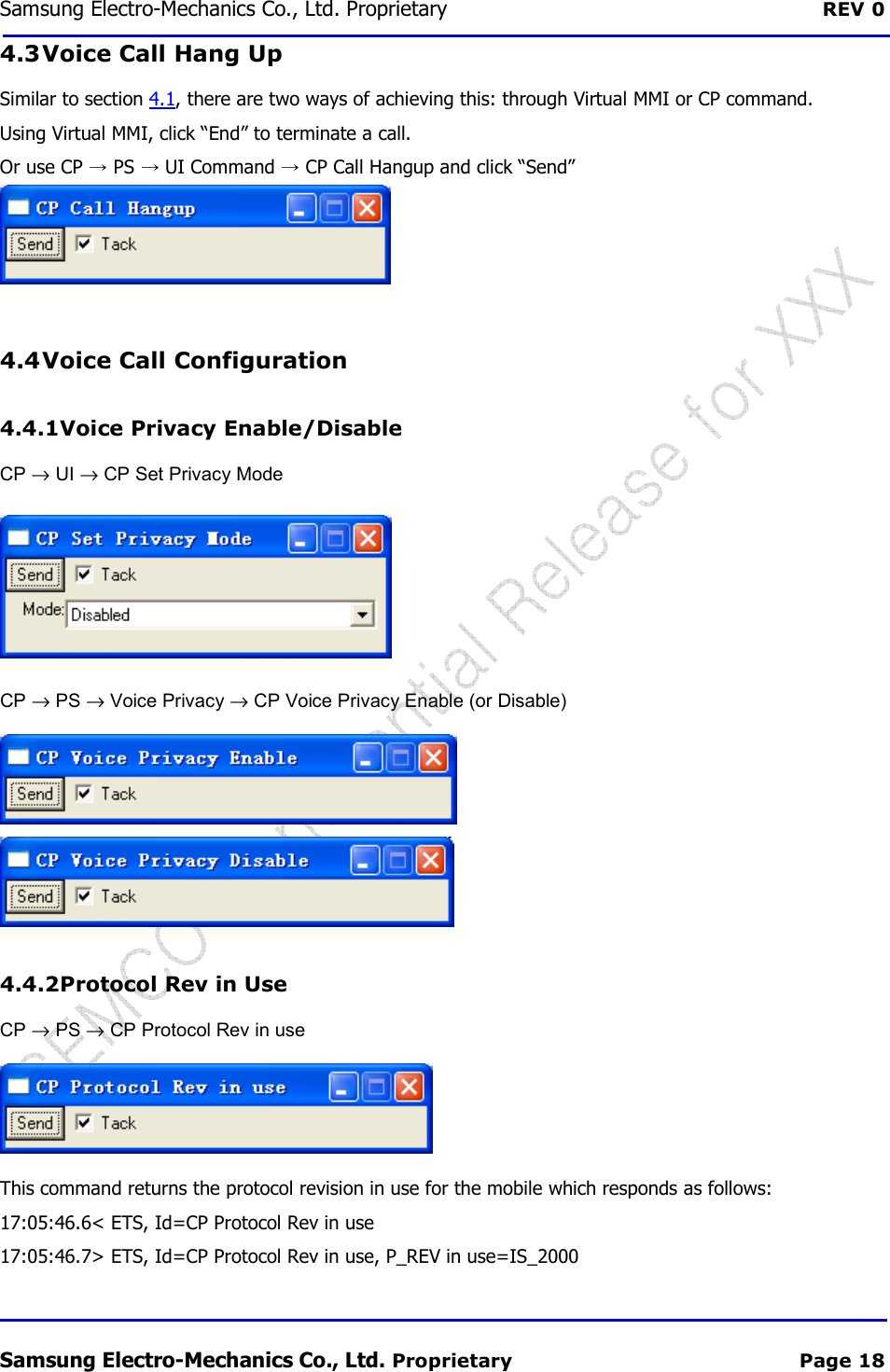
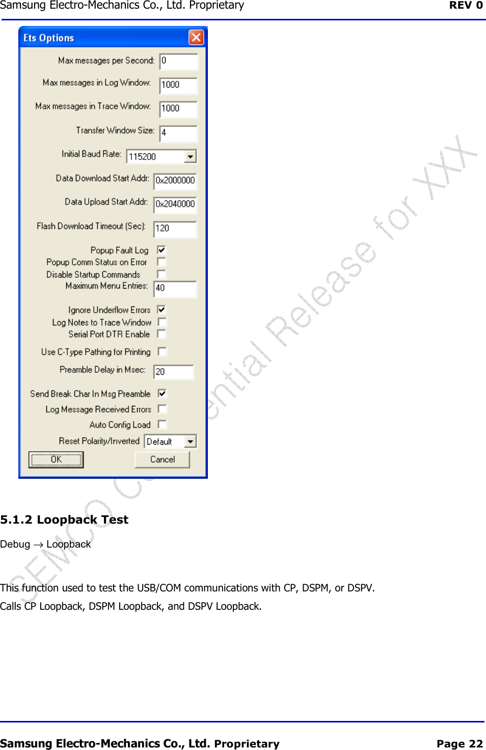
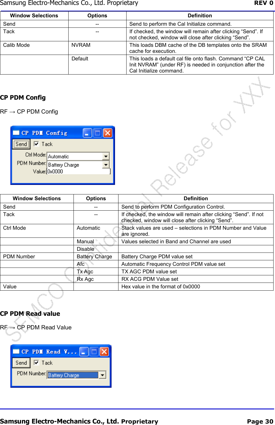
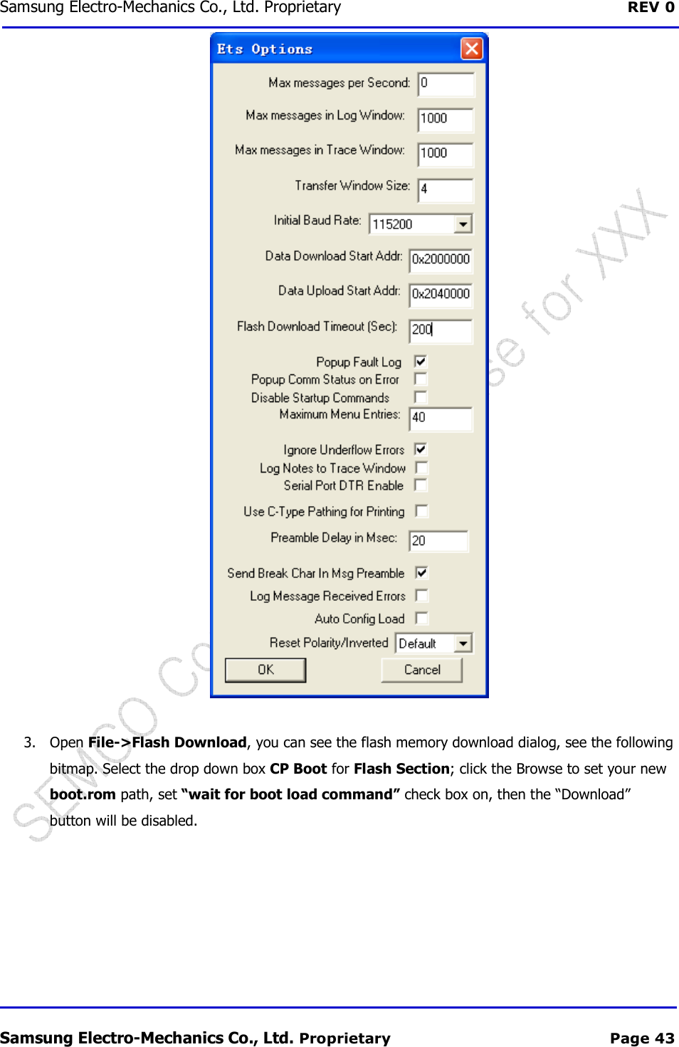
![REV 0.1 Samsung Electro 4.3 Power ConsumptionFormat RF Band 1x_RTT PCS Cellular EVDO [Rev 0] PCS Cellular SCF-V01 Samsung Electro-Mechanics Proprietary and ConfidentialPower Consumption Mode Current @ 3.3V @ Room TempIdle Mode Typ 160mA Min Tx Power Typ 250mA Cell Power Tx Max Power Typ 670mA Tx Power 23.5Max 750mA Idle Mode Typ 160mA Min Tx Power Typ 220mA Cell Power Tx Max Power Typ 610mA Tx Power 23.5dBmMax 650mA Idle Mode Typ 200mA Min Tx Power Typ 340mA Cell Power Tx Max Power Typ 900mA Tx Power 23.5dBmMax 940mA Idle Mode Typ 200mA Min Tx Power Typ 330mA Cell Power Tx Max Power Typ 800mA Tx Power 23.5dBmMax 850mA V01 User Manual Proprietary and Confidential 11/16 Condition @ Room Temp Cell Power -25dBm Tx Power 23.5dBm Cell Power -25dBm Tx Power 23.5dBm Cell Power -25dBm Tx Power 23.5dBm Cell Power -25dBm Tx Power 23.5dBm](https://usermanual.wiki/Samsung-Electro-Mechanics/SCF-V01/User-Guide-1732672-Page-11.png)
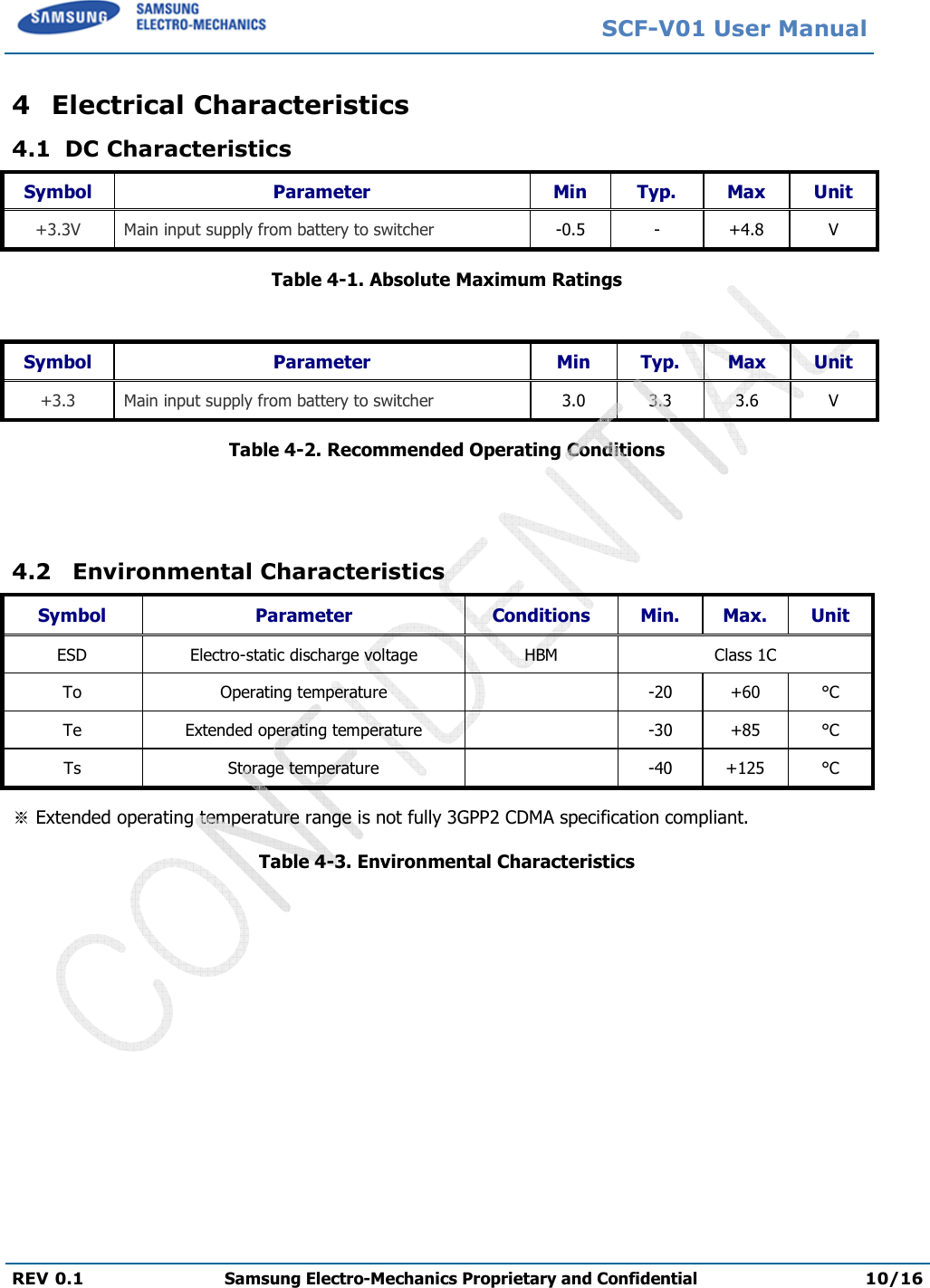
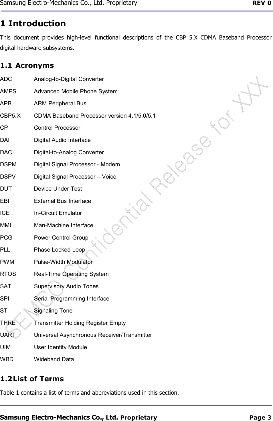
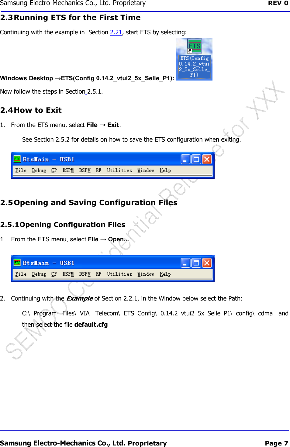
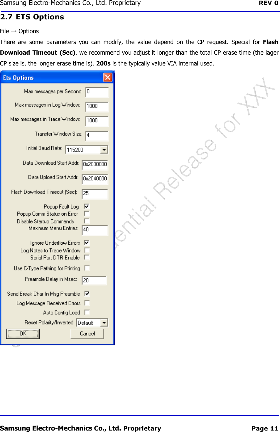
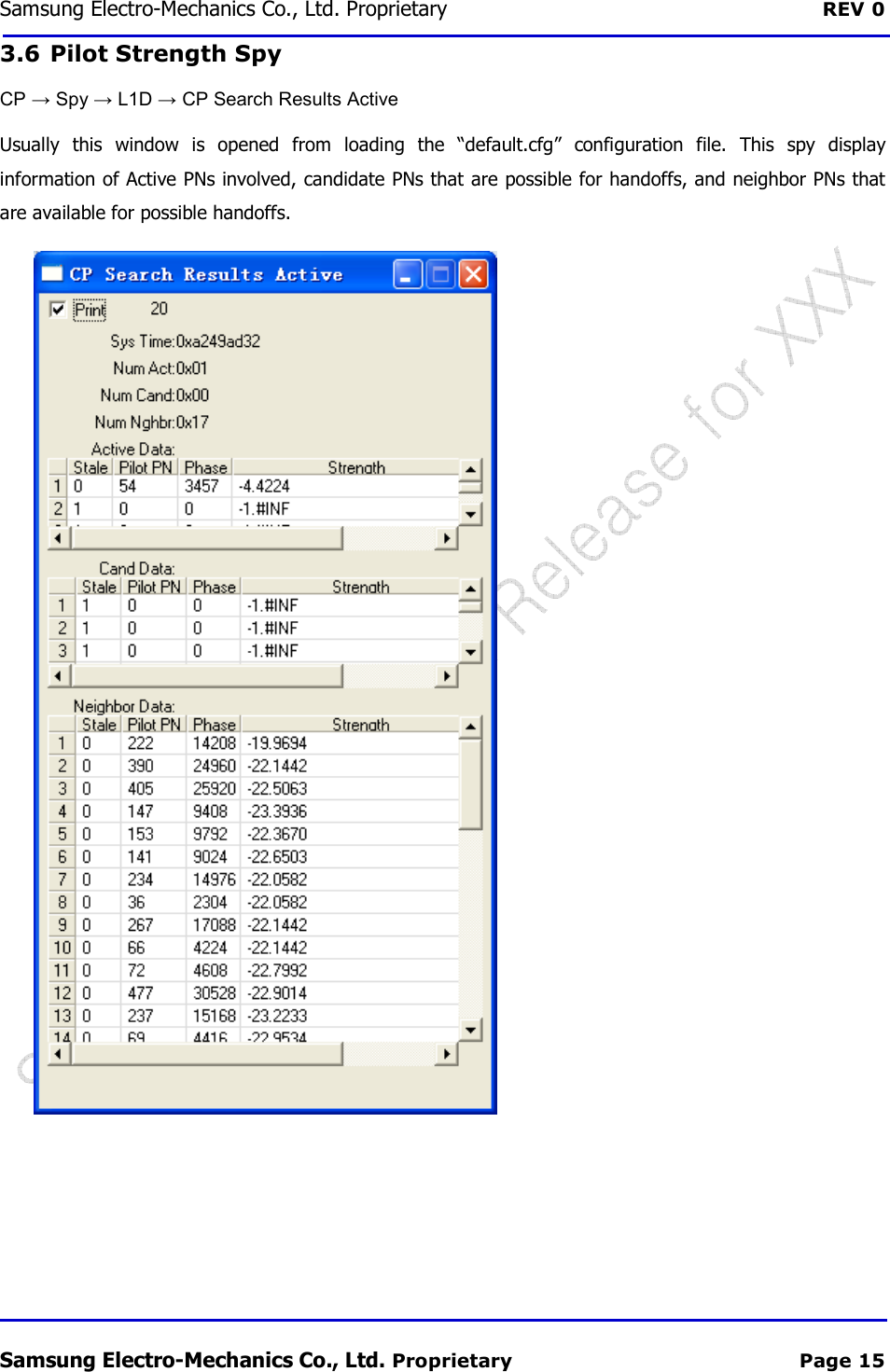
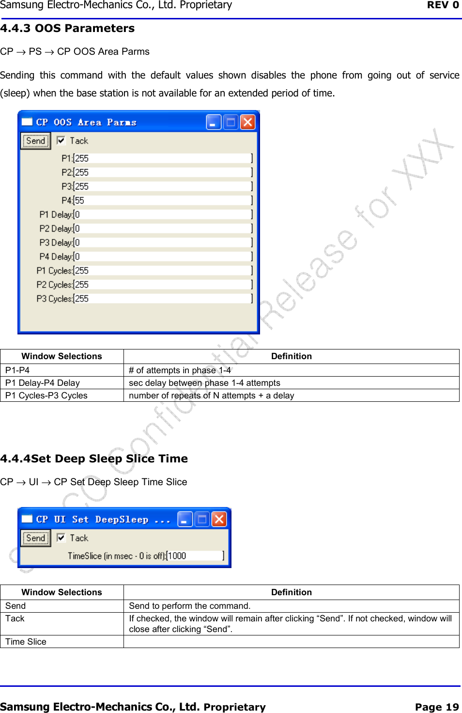
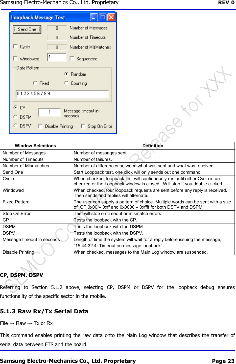
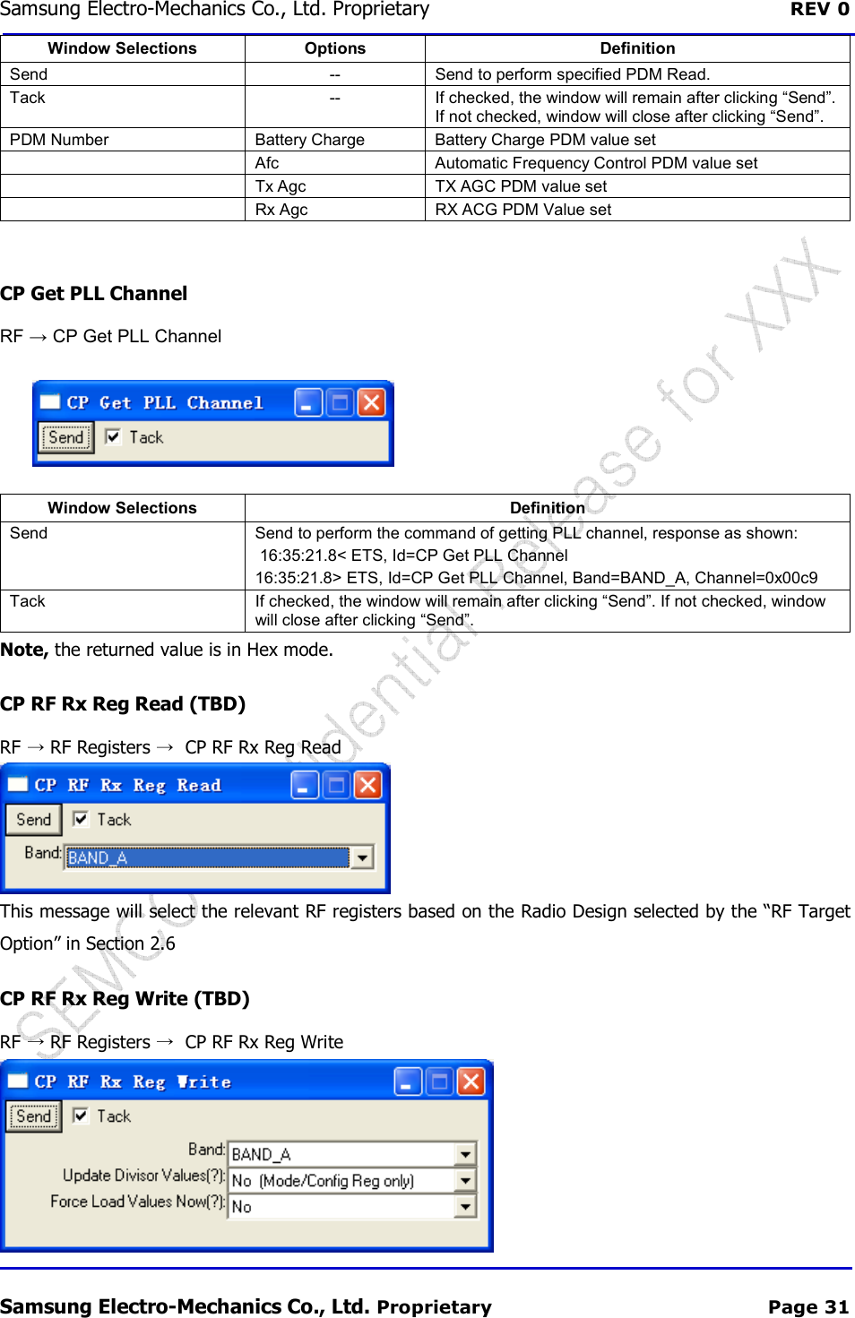
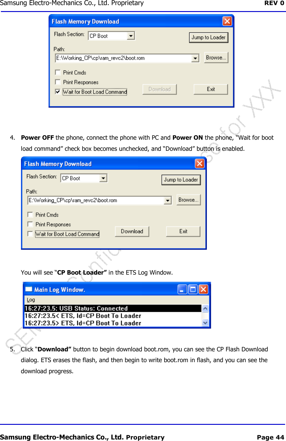
![REV 0.1 Samsung Electro 6 Label Information6.1 Module Label The Label contains Model Name, Product Code, FCC ID, MEID and Serial Number. Figure[Information] Model : SCF-V01 Product Code : CEMF10V01D0101 FCC ID : E2XSCF-V01 MEID : Mobile Equipment Id S/N : Serial Number MAIN : Main Antenna connection GPS : GPS Antenna connection AUX : Diversity Antenna connection 6.1.1 S/N(Serial Number)Ex) S Q G B 000001 S Q Company S: Samsung Custom ModelQ : CEMF10V01D0101Table SCF-V01 Samsung Electro-Mechanics Proprietary and ConfidentialInformation The Label contains Model Name, Product Code, FCC ID, MEID and Serial Number. Figure 6-1. Label Information : CEMF10V01D0101 Identifier : Main Antenna connection : GPS Antenna connection Antenna connection S/N(Serial Number) Q G B Custom Model CEMF10V01D0101 Year F:2011 G:2012 Month 1~9:Jan~SEP A:OCT, B:Nov, C:Dec Table 6-1. Serial Number Information V01 User Manual Proprietary and Confidential 14/16 The Label contains Model Name, Product Code, FCC ID, MEID and Serial Number. 000001 000001~FFFFFF Serial No(Hex)](https://usermanual.wiki/Samsung-Electro-Mechanics/SCF-V01/User-Guide-1732672-Page-14.png)
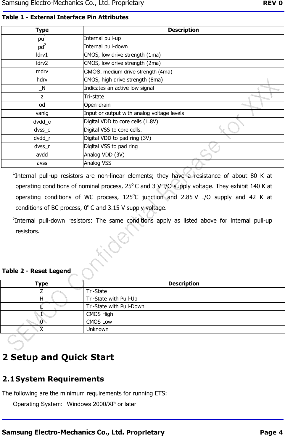
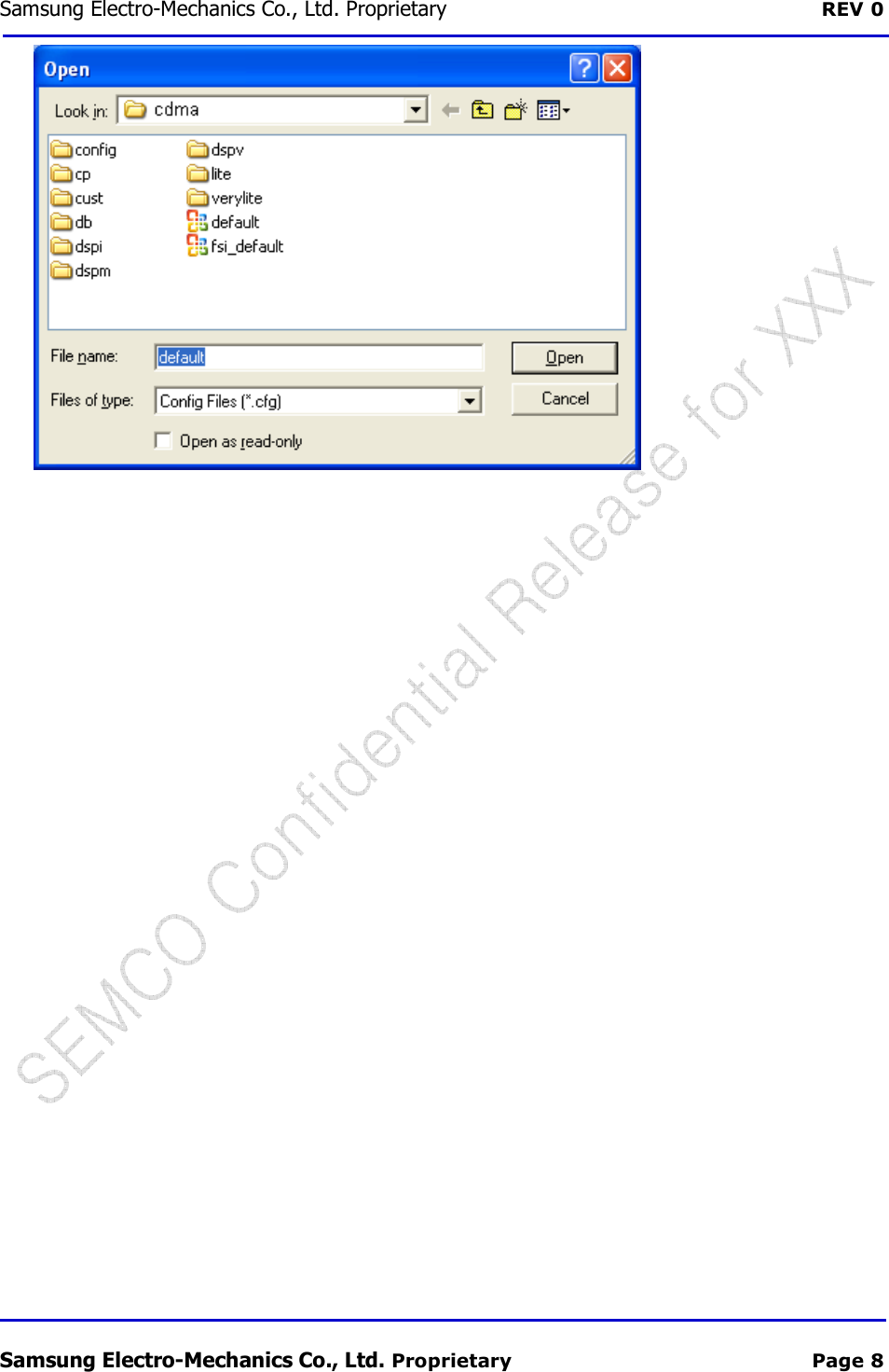
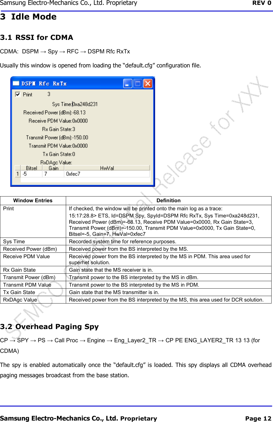
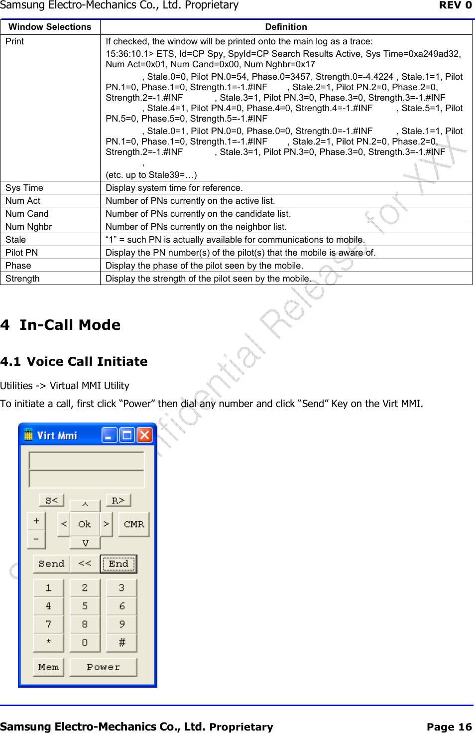
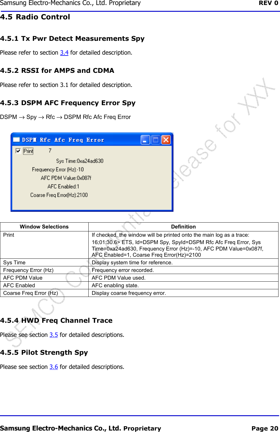
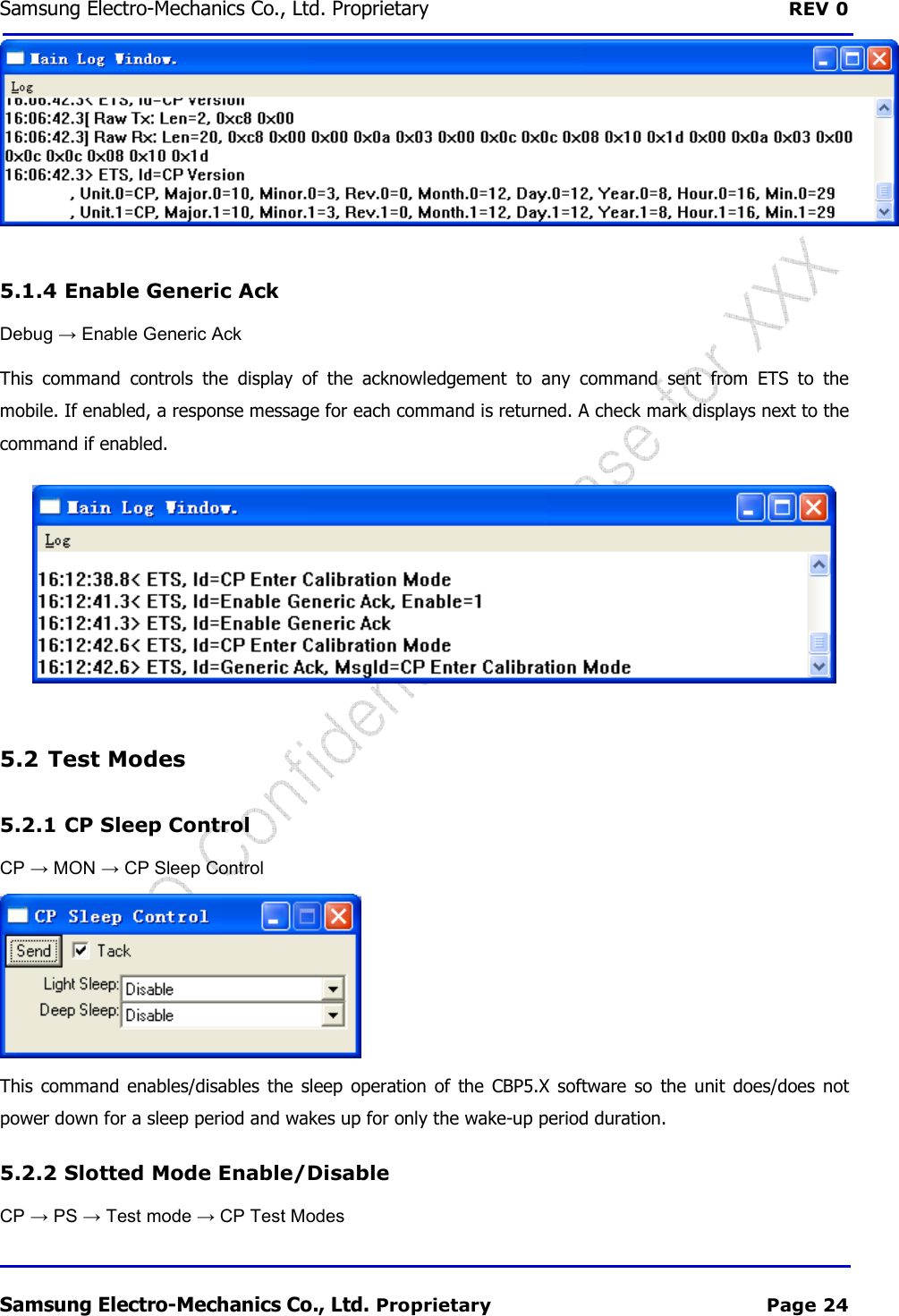
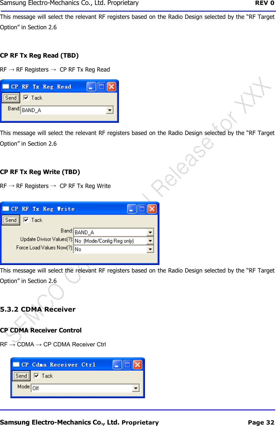
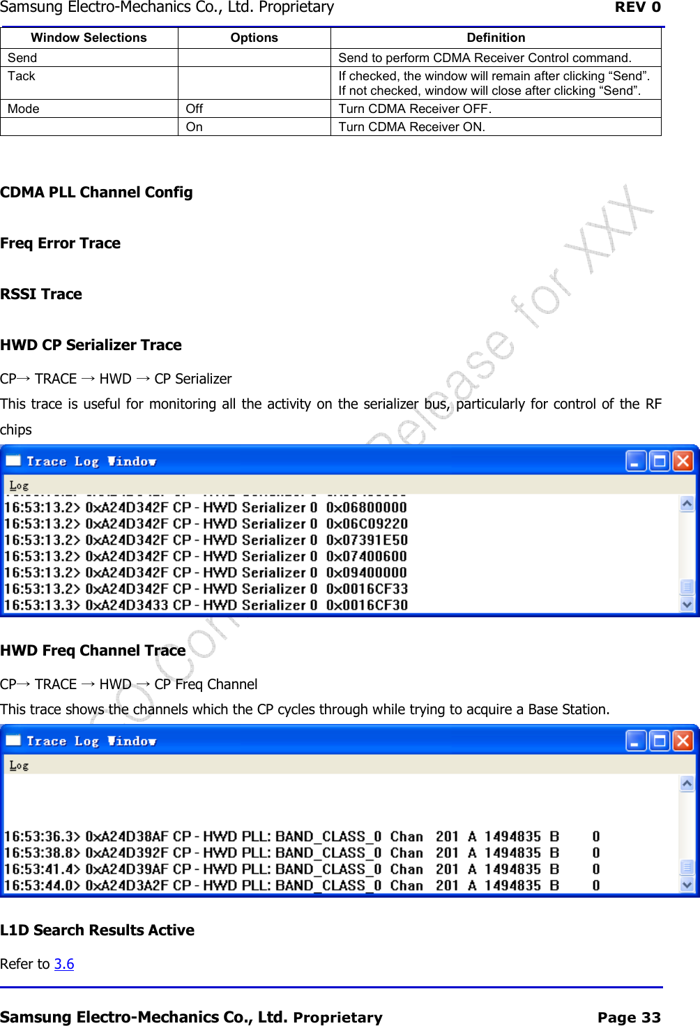
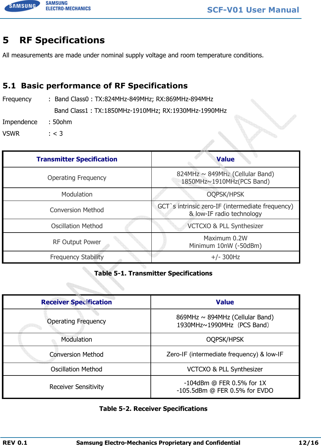
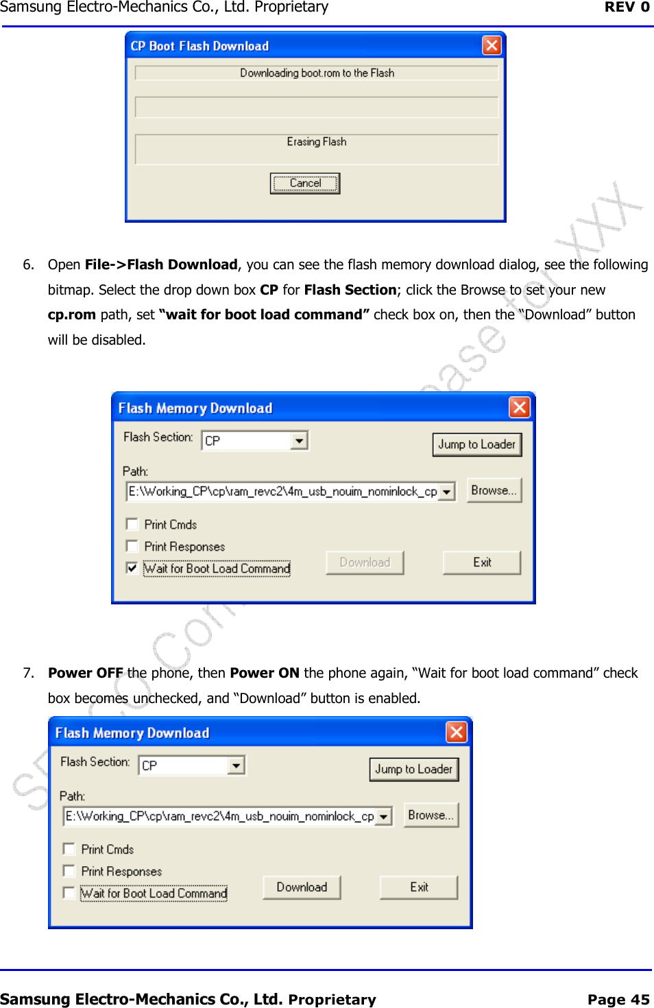
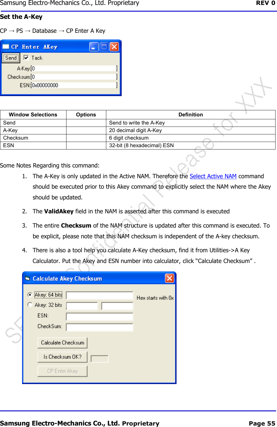
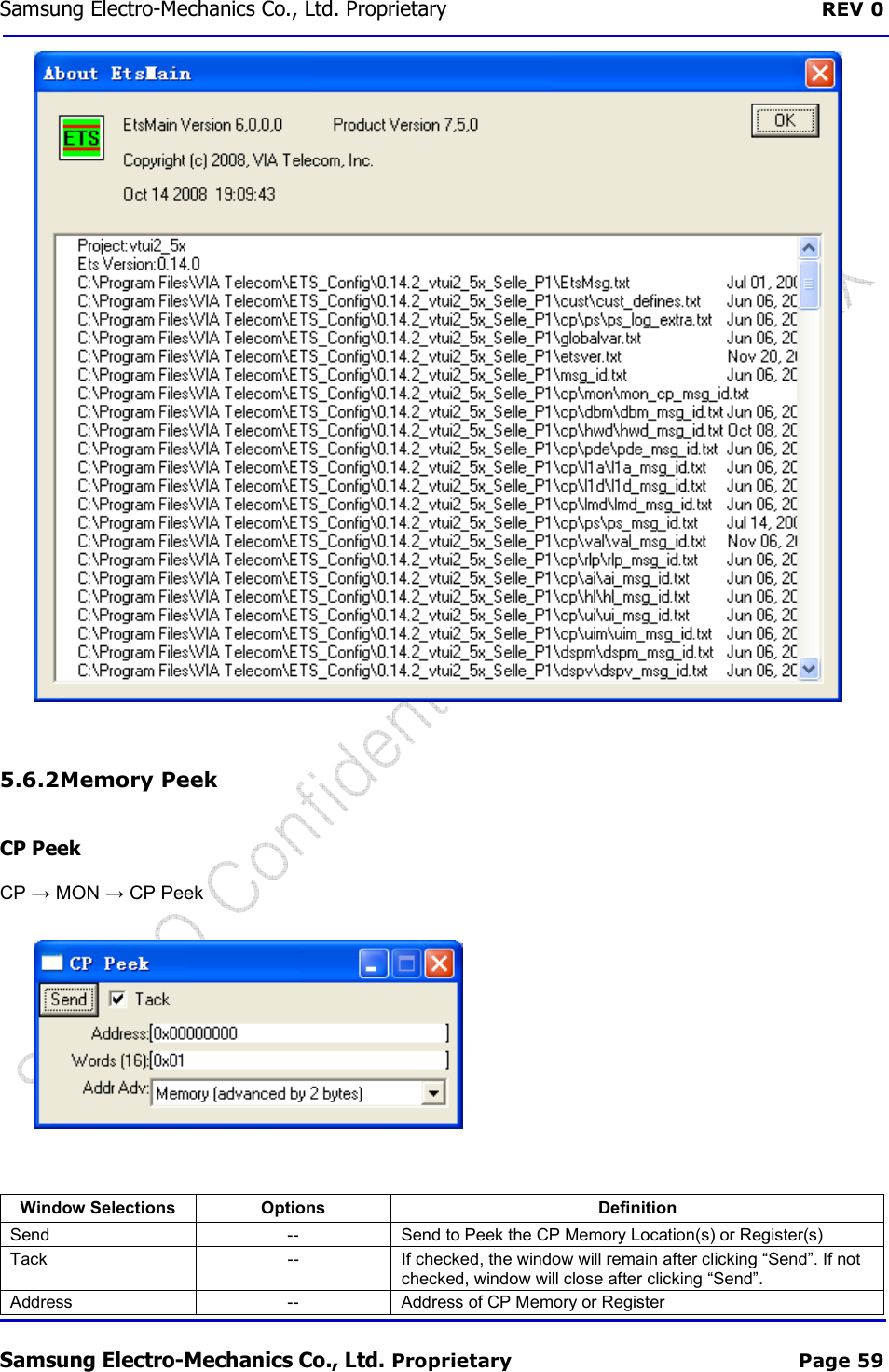
![Samsung Electro-Mechanics Co., Ltd. Proprietary REV 0 Samsung Electro-Mechanics Co., Ltd. Proprietary Page 37 Set Busy Idle Status Tx Fixed Freq Tx Calibration 5.3.4 AFC DSPM AFC Get Params DSPM AFC Config AFC Cal Parameters (L1D) 5.3.5 RF Pin Control CP TXON Control RF → CP TXON Control Window Selections Options Definition Send -- Send to enable TXON Control Tack -- If checked, the window will remain after clicking “Send”. If not checked, window will close after clicking “Send”. TxOn [0:4] Off Turn TxOn OFF. On Turn TxOn ON. Auto Allow CBP software to control the TxOn CP RXON Control RF → CP RXON Control](https://usermanual.wiki/Samsung-Electro-Mechanics/SCF-V01/User-Guide-1732672-Page-54.png)
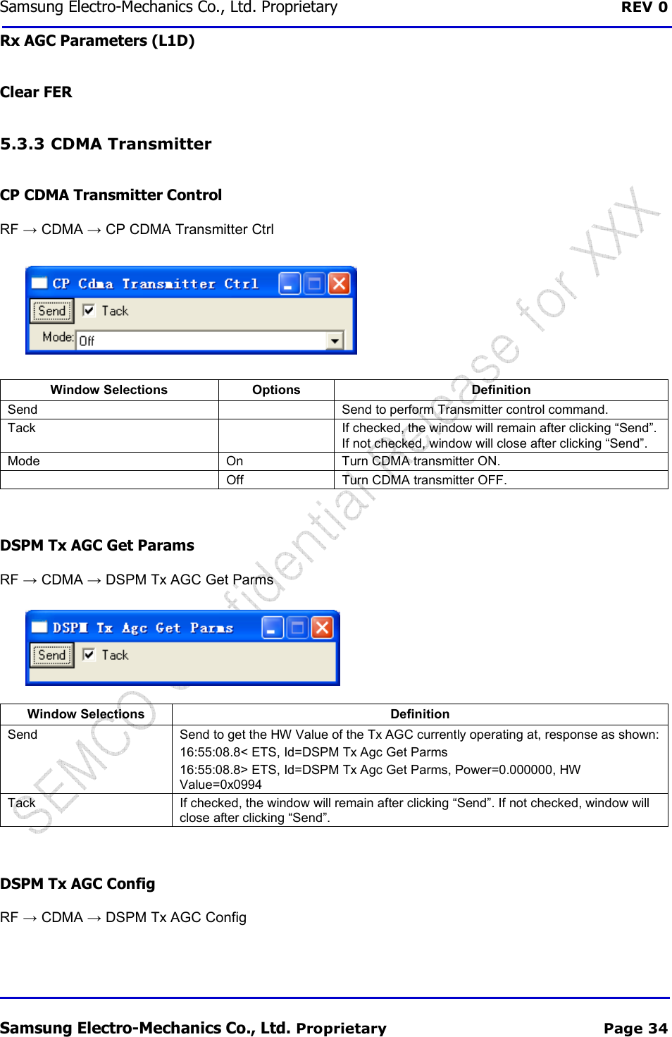
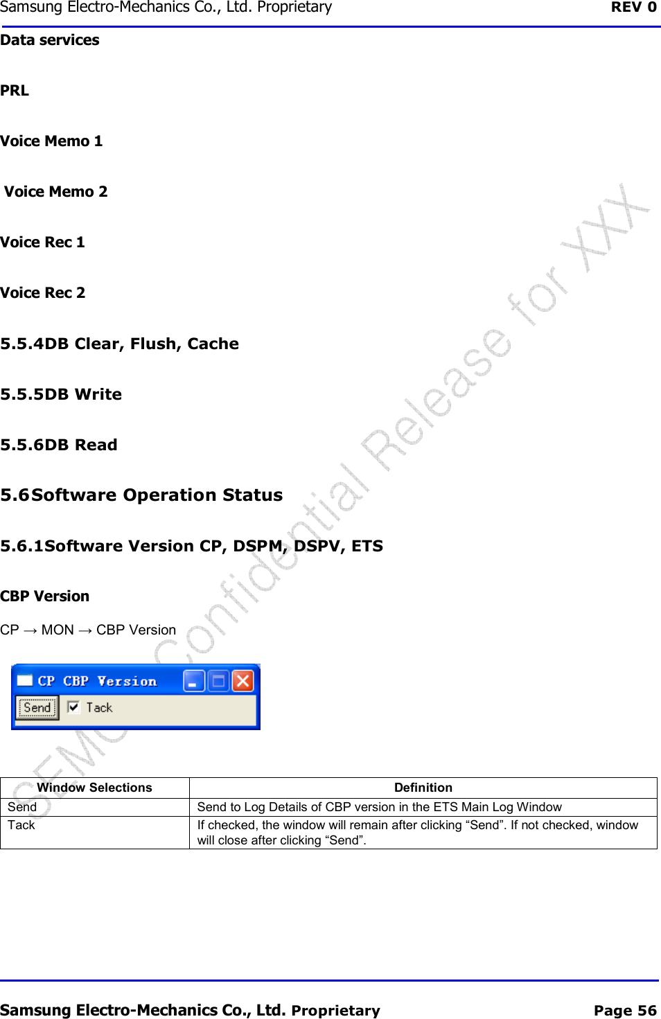
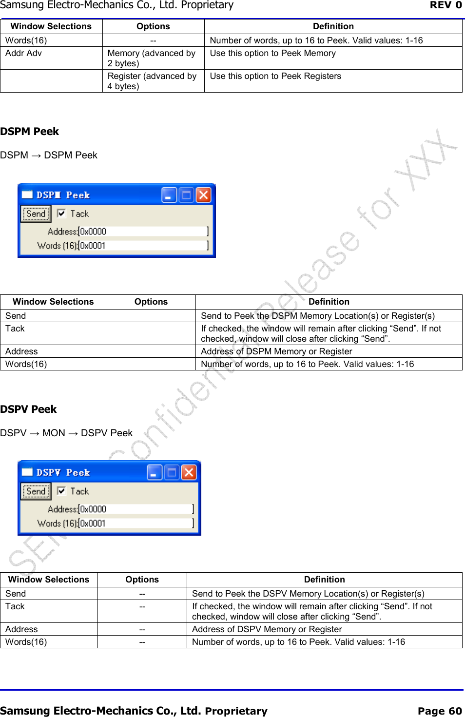
![Samsung Electro-Mechanics Co., Ltd. Proprietary REV 0 Samsung Electro-Mechanics Co., Ltd. Proprietary Page 38 Window Selections Options Definition Send Send to enable RFON Control Tack If checked, the window will remain after clicking “Send”. If not checked, window will close after clicking “Send”. RfOn [0:7] Off Turn RfOn OFF. On Turn RfOn ON. Auto Allow CBP software to control the RfOn CP TXON Read RF → CP TXON Read](https://usermanual.wiki/Samsung-Electro-Mechanics/SCF-V01/User-Guide-1732672-Page-55.png)
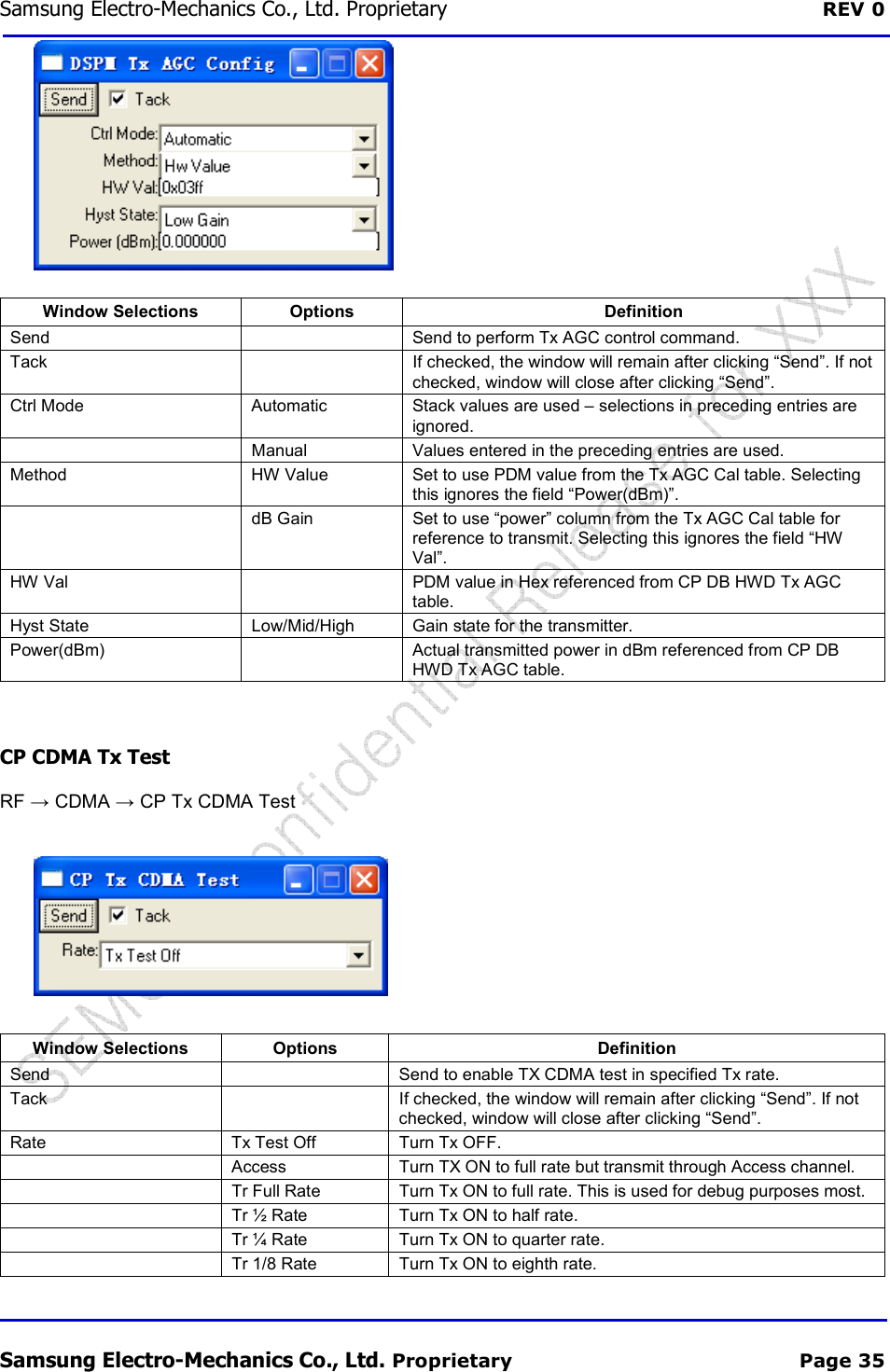
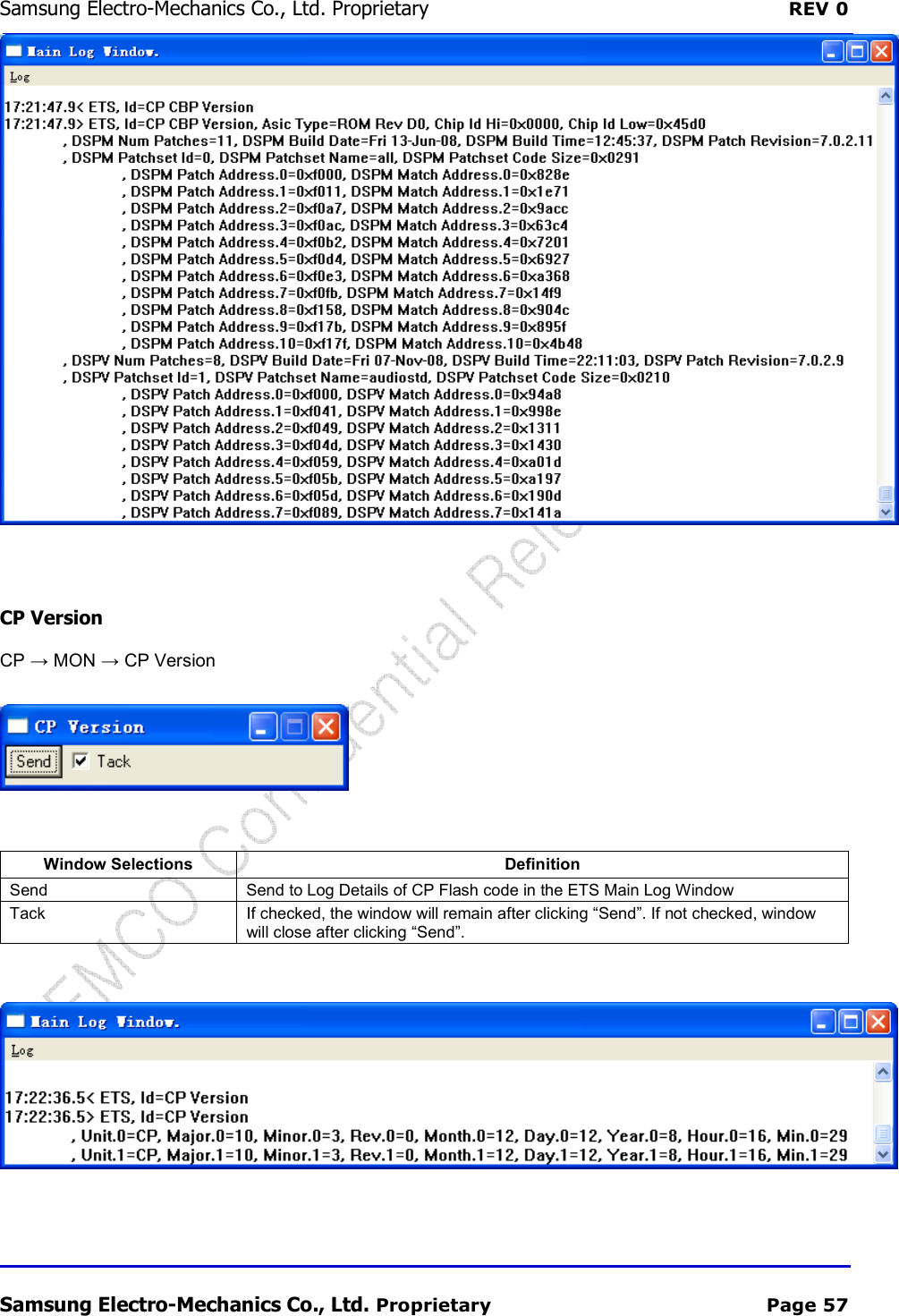
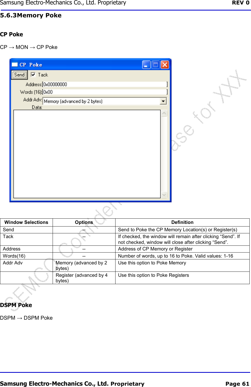
![Samsung Electro-Mechanics Co., Ltd. Proprietary REV 0 Samsung Electro-Mechanics Co., Ltd. Proprietary Page 39 CP RXON Read RF → CP RXON Read 5.3.6 GPIO Control GPIO Read / GPIO Write CP → MON → GPIO → CP Read GPIO Window Selections Options Definition Send -- Send to read the relevant GPIO. Caution: This command will set the GPIO to INPUT mode and perform the read. The original state is not preserved so this command should only be performed on GPIOs which are known to be Inputs. Tack -- If checked, the window will remain after clicking “Send”. If not checked, window will close after clicking “Send”. GPIO Num [0:47] Read the Relevant GPIO CP → MON → GPIO → CP Set Clear GPIO](https://usermanual.wiki/Samsung-Electro-Mechanics/SCF-V01/User-Guide-1732672-Page-56.png)
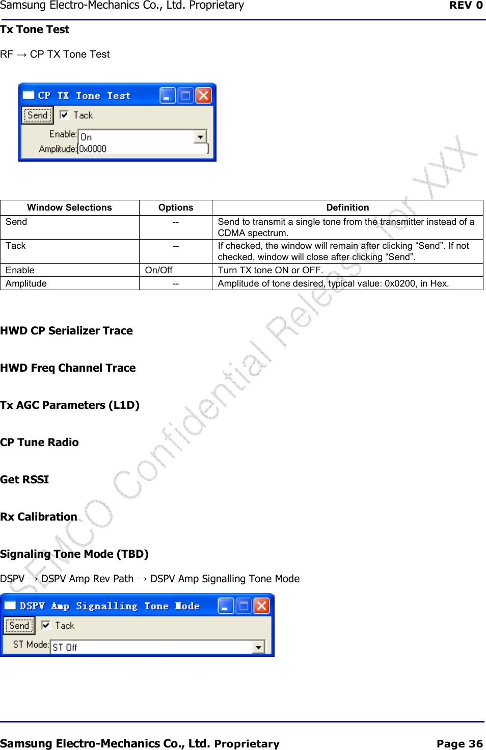
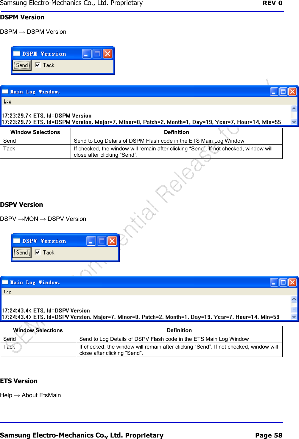
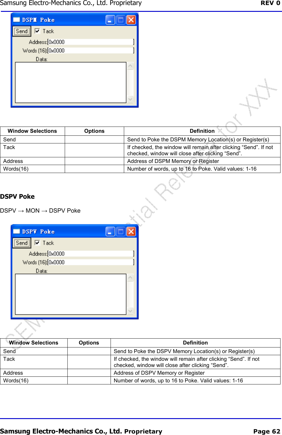
![Samsung Electro-Mechanics Co., Ltd. Proprietary REV 0 Samsung Electro-Mechanics Co., Ltd. Proprietary Page 40 Window Selections Options Definition Send Send to read the relevant GPIO Tack If checked, the window will remain after clicking “Send”. If not checked, window will close after clicking “Send”. GPIO Num [0:47] Read the Relevant GPIO Action SET Sets the GPIO to “0” CLEAR Clears the GPIO to “1” GPIO Read Monitor CP → MON →GPIO → CP Monitor GPIO Window Selections Options Definition Send -- Send to Monitor the relevant GPIO Tack -- If checked, the window will remain after clicking “Send”. If not checked, window will close after clicking “Send”. GPIO Num [0:47] GPIO (trace ???) 5.3.7 Serializer This section should be read in conjunction with the Serial Programmer chapters in References [2][3]. Serializer Configuration CP → HWD → CP Serializer Config](https://usermanual.wiki/Samsung-Electro-Mechanics/SCF-V01/User-Guide-1732672-Page-57.png)
![Samsung Electro-Mechanics Co., Ltd. Proprietary REV 0 Samsung Electro-Mechanics Co., Ltd. Proprietary Page 41 Window Selections Definition Send Send to set the Serializer Configuration Tack If checked, the window will remain after clicking “Send”. If not checked, window will close after clicking “Send”. Control Programs the register SER0_CTRL (listed as SER#_CTRL in Reference [3]). The PTR field can only be set to “000”. Load Enable Programs the register SER0_LE (listed as SER#_LE in Reference [3]) NumBits-1 to Shift Programs the register SER0_BC (listed as SER#_BC in Reference [3]) Serializer Write CP → HWD → CP Serializer Write Window Selections Definition Send Send to set the Serializer Configuration Tack If checked, the window will remain after clicking “Send”. If not checked, window will close after clicking “Send”. Data Write Data to Serializer, which has been configured (see Section 0). This data is loaded into the registers SER0_D1, SER0_D0 (listed as SER#_D1, SER#_D0 in Reference [3]) 5.4 SMS Here, we only provide a brief summary to allow the user the user to access the SMS menu. The details of the SMS messages are covered in great detail in [6], while background information on SMS is provided in [5].](https://usermanual.wiki/Samsung-Electro-Mechanics/SCF-V01/User-Guide-1732672-Page-58.png)
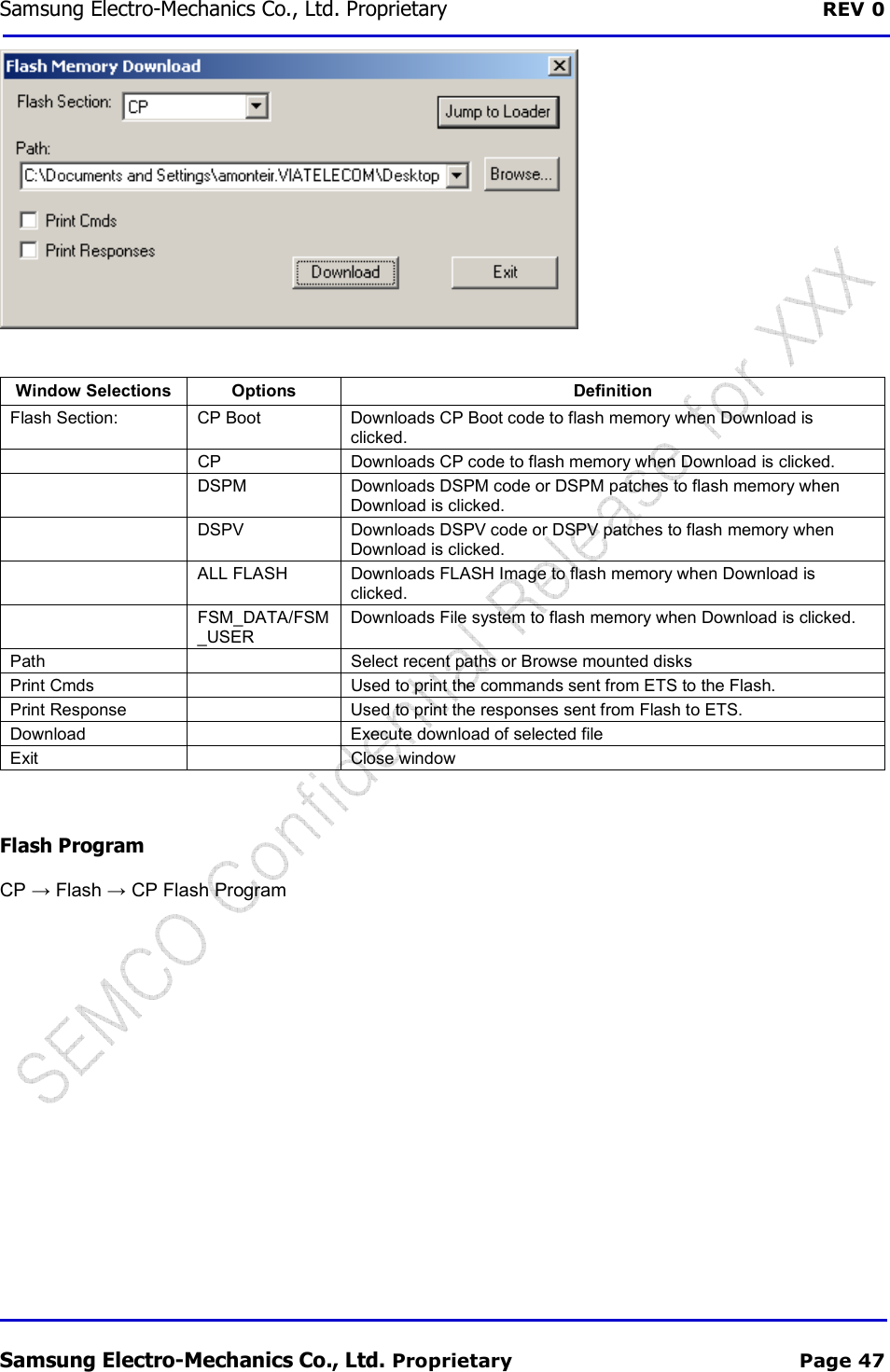
![Samsung Electro-Mechanics Co., Ltd. Proprietary REV 0 Samsung Electro-Mechanics Co., Ltd. Proprietary Page 46 You will see “CP Boot Loader” in the ETS Log Window. 8. Click “Download” button to begin download cp.rom, you can see the CP Flash Download dialog. ETS erases the flash, and then begin to write cp.rom in flash, and you can see the download progress. 9. After download finished, power off the phone (If there is a battery in your phone, please remove and re-insert), then power on the phone. Flash Download FOR CDS Products (NOT FOR Reference Phones) File → Flash Download Use to download CP Boot, CP, DSPM, and DSPV code to flash memory. System must be in boot mode to download any section of flash. See Reference [8] for more details.](https://usermanual.wiki/Samsung-Electro-Mechanics/SCF-V01/User-Guide-1732672-Page-63.png)
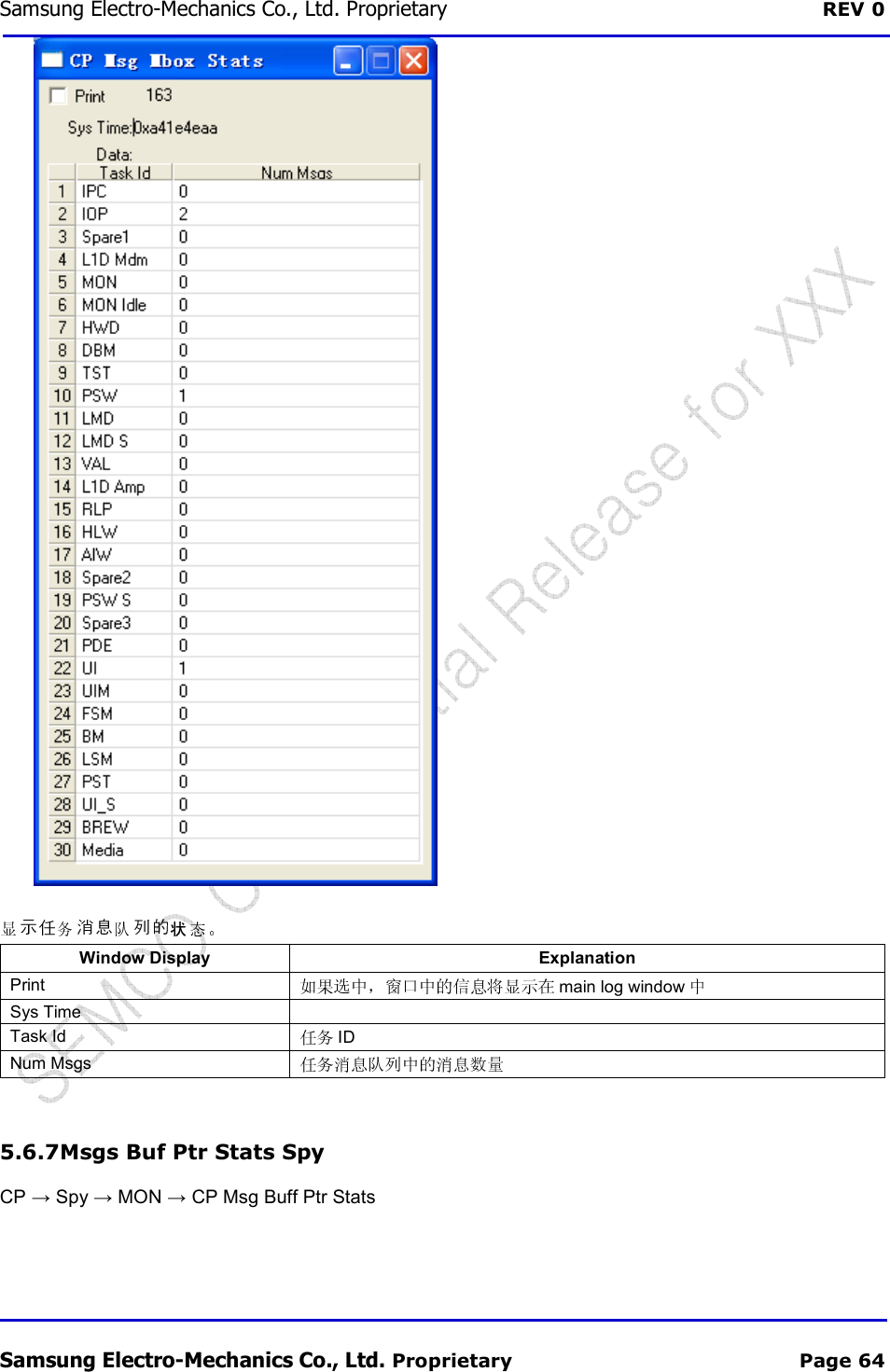
![Samsung Electro-Mechanics Co., Ltd. Proprietary REV 0 Samsung Electro-Mechanics Co., Ltd. Proprietary Page 63 5.6.4 Disabling All Spies And Traces 5.6.5 Msgs Buffer Stats Spy CP → Spy → MON → CP Msg Buff Stats Window Display Description Print main log window Sys Time Num Msg Buffs In Use 1-4 Max Num Msg Buffs Used 1-4 Num Msg Buffs[1:4] In Use 1-4 Max Num Msg Buffs[1:4] 1-4 Max Msg Buff[1:4] Size 1-4 5.6.6 Msgs Mbox Stats Spy CP → Spy → MON → CP Msg Mbox Stats](https://usermanual.wiki/Samsung-Electro-Mechanics/SCF-V01/User-Guide-1732672-Page-80.png)
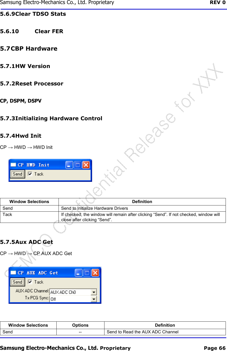
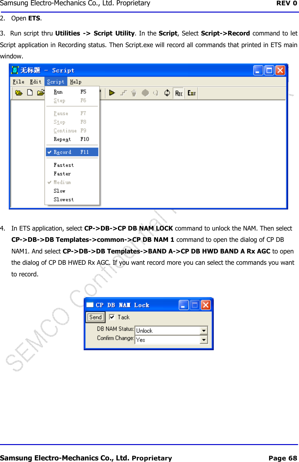
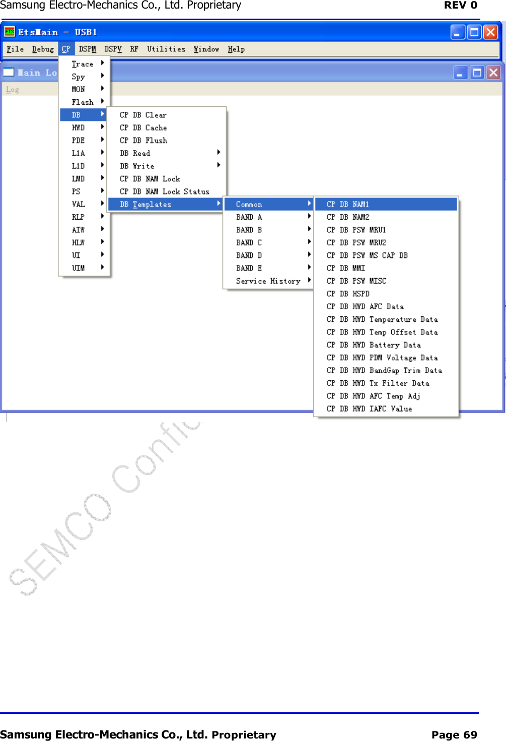
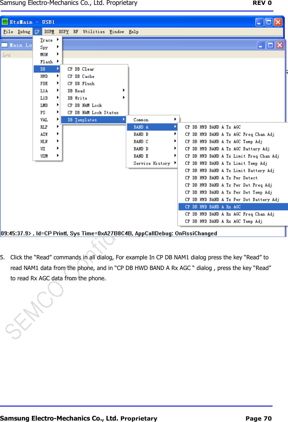
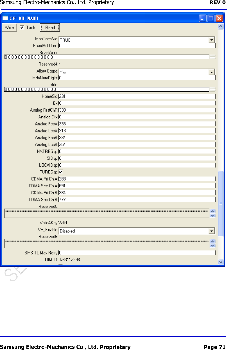
![Samsung Electro-Mechanics Co., Ltd. Proprietary REV 0 Samsung Electro-Mechanics Co., Ltd. Proprietary Page 67 Window Selections Options Definition Tack -- If checked, the window will remain after clicking “Send”. If not checked, window will close after clicking “Send”. AUX ADC Channel AUX ADC Ch[0-15] Read the Relevant AUX ADC Channel. There are 16 channels [0-15] Tx PCG Sync Off Take the AUX ADC reading immediately On Wait till an Active PCG to make a measurement. This is especially usefully for measuring Transmit Power from the Power Amplifier; selecting this option ensures that the Power Amplifier is ON. 6 Utilities 6.1 Virtual MMI Utilities -> Virtual MMI Utility, operate the handset just link press keypad. 6.2 Script Utility Utilities -> Script Utility The following steps descript how to record an ETS script. Give an example of record data of command cp->DB->DB Templates->common->cp DB NAM 1, CP/DB/DB Templates/cellular/CP DB HWD Rx AGC. 1. Connect the phone to your computer, make sure all connection is ok.](https://usermanual.wiki/Samsung-Electro-Mechanics/SCF-V01/User-Guide-1732672-Page-84.png)