Samsung Electro Mechanics SCF-V01 3G CDMA PCIe Full Mini Card User Manual SCF V01 120618x
Samsung Electro Mechanics 3G CDMA PCIe Full Mini Card SCF V01 120618x
user manual

REV 0.1
Samsung Electro
SCF-V01
User Manual
VIA Telecom CBP7.
1C CDMA
REV 0.1
Samsung Electro-Mechanics
2012-06-18
Summary
This datasheet presents
the
1x Rel.0 and 1X EV-DO Rev.
A
SCF-
V01
Samsung Electro
-Mechanics
Proprietary and Confidential
1C CDMA
Solution
the
general performance and specifications of
A
Module.
© 2012 Samsung Electro-
Mechanics. All rights reserved
The names of actual companies and products mentioned
herein may be the trademarks of their respective owners.
No part of this document may
be reproduced, stored in a
retrieval system, or transmitted in any form
means without the express written consent of Samsung
Electro-Mechanics.
This document is subject to
change without notice
V01
User Manual
Proprietary and Confidential
1/16
general performance and specifications of
SCF-V01 CDMA2000 A
Mechanics. All rights reserved
The names of actual companies and products mentioned
herein may be the trademarks of their respective owners.
be reproduced, stored in a
retrieval system, or transmitted in any form
or by any
means without the express written consent of Samsung
change without notice
.

REV 0.1
Samsung Electro
Table of Contents
1 GENERAL
DESCRIPTION
1.1 F
UNCTIONAL
D
ESCRIPTION
1.2 F
EATURES
................................
1.3 A
PPLICATIONS
................................
1.4 B
LOCK
D
IAGRAM
................................
2 DIMENSION AND
PIN ASSIGNMENTS
2.1 M
ECHANICAL
D
IMENSION
................................
2.2 A
NTENNA
C
ONNECTION
................................
2.3 G
ROUND
C
ONNECTION
................................
3 PIN
ASSIGNMENTS AND DESC
3.1 P
IN
A
SSIGNMENTS
................................
3.2 P
IN
D
ESCRIPTION
................................
4
ELECTRICAL CHARACTER
4.1 DC
C
HARACTERISTICS
................................
4.2 E
NVIRONMENTAL
C
HARACTERISTI
4.3 P
OWER
C
ONSUMPTION
................................
5 RF SPECIFICATIONS
................................
5.1 B
ASIC PERFORMANCE OF
RF
6 LABEL INFORMATION
................................
6.1 M
ODULE
L
ABEL
................................
7 SAFETY INFORMATION
................................
7.1 C
ERTIFICATION
................................
7.2 C
AUTION
................................
REVISION HISTORY
................................
SCF-
V01
Samsung Electro
-Mechanics
Proprietary and Confidential
DESCRIPTION
................................................................
................................
ESCRIPTION
................................................................
................................
................................
................................
................................
................................
................................
................................
................................
................................
................................
PIN ASSIGNMENTS
................................
................................
................................
................................
................................
................................
................................
................................
................................
................................
................................
ASSIGNMENTS AND DESC
RIPTIONS ................................
................................
................................
................................
................................
................................
................................
................................
ELECTRICAL CHARACTER
ISTICS ................................
................................
................................
................................
................................
HARACTERISTI
CS
................................
................................
................................
................................
................................
................................
................................
................................
RF
S
PECIFICATIONS
................................
................................
................................
................................
................................
................................
................................
................................
................................
................................
................................
................................
................................
................................
................................
................................
................................
................................
................................
................................
V01
User Manual
Proprietary and Confidential
2/16
................................
.... 3
................................
..... 3
................................
.......................... 3
................................
..................... 3
................................
.................. 4
................................
................ 5
................................
........ 5
................................
.......... 6
................................
........... 6
................................
........... 7
................................
................ 7
................................
................ 8
................................
...................... 10
................................
......... 10
................................
......................... 10
................................
......... 11
................................
........ 12
................................
.............. 12
................................
...... 14
................................
.................. 14
................................
.... 15
................................
................. 15
................................
......................... 15
................................
................ 16

REV 0.1
Samsung Electro
1 General
Description
1.1
Functional Description
SCF-V01 is the cellular
module for
embedded and wireless M2M
Management and software, which
It supports Cell and PCS bands.
1.2
Features
Dual band cellular and PCS voice and data
Variant module :
CDMA2000 A 1x Rel.0
Optional GPS and RX
Diversity reception
Support Cell and PCS bands
GPS (optional)
3
U.FL Antenna port : Main, AUX
Low
power consumption
Dimension: 50.95 x 30
.0
USB2.0 full speed USB driver
RoHS compliant
Operating temperature
1.3
Applications
All CDMA M2M devices (Energy, Industrial & Infrastructure, Security, etc.)
CDMA equipment laptop PC
CDMA portable device (Tablet, MID, PMP, etc.)
Desktop CDMA CPE
SCF-
V01
Samsung Electro
-Mechanics
Proprietary and Confidential
Description
Functional Description
module for
either the CDMA2000 A 1x Rel.0 or
1X EV/DO Rev
applications. It
provides all the RF, Processing, Memory, Power
Management and software, which
is based on the Via Telecom CBP6.x
or CBP7.x
It supports Cell and PCS bands.
Dual band cellular and PCS voice and data
CDMA2000 A 1x Rel.0
or 1X EV/DO Rev. A
Diversity reception
Support Cell and PCS bands
U.FL Antenna port : Main, AUX
, & GPS (50 Ohm)
power consumption
.0
mm / Hmax : 4.75 mm
USB2.0 full speed USB driver
range: -20 to 60
All CDMA M2M devices (Energy, Industrial & Infrastructure, Security, etc.)
CDMA equipment laptop PC
CDMA portable device (Tablet, MID, PMP, etc.)
V01
User Manual
Proprietary and Confidential
3/16
1X EV/DO Rev
. A at
provides all the RF, Processing, Memory, Power
or CBP7.x
solution.
All CDMA M2M devices (Energy, Industrial & Infrastructure, Security, etc.)
REV 0.1
Samsung Electro
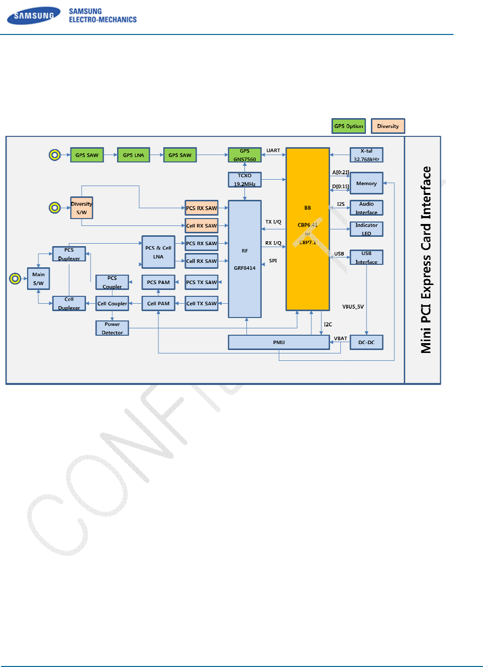
1.4
Block Diagram
The following SCF-V01
block diagram highlights the major func
Figure
SCF-
V01
Samsung Electro
-Mechanics
Proprietary and Confidential
block diagram highlights the major func
tional blocks and interfaces.
Figure
1-1. SCF-V01 Hardware Block Diagram
V01
User Manual
Proprietary and Confidential
4/16
tional blocks and interfaces.
REV 0.1
Samsung Electro
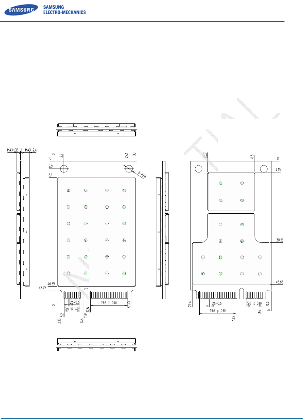
2
Dimension and
2.1
Mechanical Dimension
Form factor :
Standard PCI Express
(Full-
Mini Card)
Size : W x L x H (50.95 x 30.0 x 4.75mm)
Weight : 9.8g
Figure 2
-
SCF-
V01
Samsung Electro
-Mechanics
Proprietary and Confidential
Dimension and
Pin Assignments
Mechanical Dimension
Standard PCI Express
®
Mini Card Electromechanical Speci
Mini Card)
Size : W x L x H (50.95 x 30.0 x 4.75mm)
with 1.0mm PCB
-
1. SCF-V01 Mechanical Dimensio
n (Top View)
V01
User Manual
Proprietary and Confidential
5/16
Mini Card Electromechanical Speci
fication
n (Top View)
REV 0.1
Samsung Electro
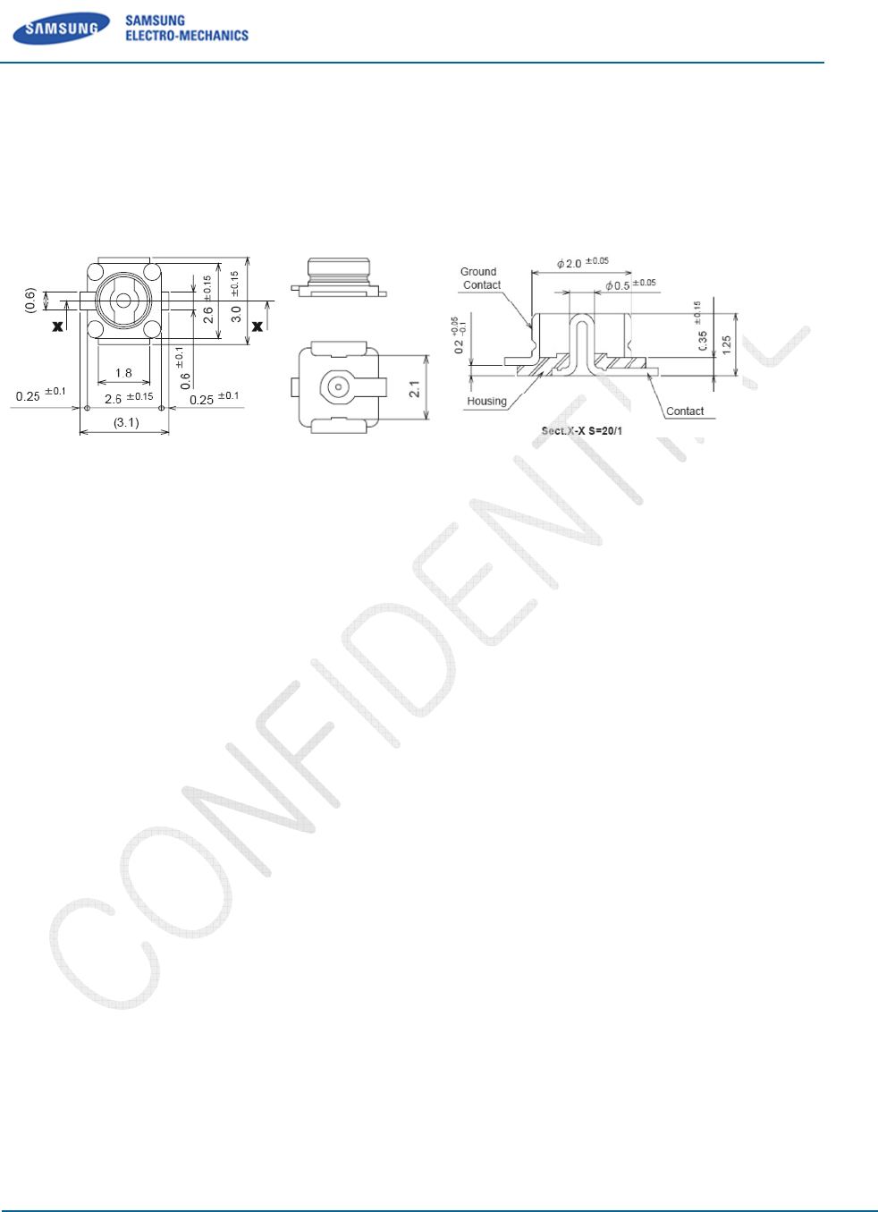
2.2
Antenna Connection
U.FL connector for the M
ain ANT,
Figure 2
-
A
ttaching an antenna to the
Use a Hirose U.FL connector (Part No. : U.FL
antenna to a connection point on the SCF
Match coaxial
connections between the SCF
Mini
mize RF cable losses
2.3
Ground
Connection
Connecting the SCF-
V01 to system ground :
Connect to system ground for preventing noise leakage.
Connect with host connector, two mounting holes, and
SCF-
V01
Samsung Electro
-Mechanics
Proprietary and Confidential
Antenna Connection
ain ANT,
Diversity ANT, and GPS ANT
-
2.
Antenna Connector Mechanical Dimension
ttaching an antenna to the
SCF-V01 :
Use a Hirose U.FL connector (Part No. : U.FL
-R-SMT, CL No. : 331
-
antenna to a connection point on the SCF
-V01.
connections between the SCF
-V01 and the antenna to 50
Ω.
mize RF cable losses
between the SCF-V01 and
the antenna to less than 0.5 dB.
Connection
V01 to system ground :
Connect to system ground for preventing noise leakage.
Connect with host connector, two mounting holes, and
PCI express®
m
V01
User Manual
Proprietary and Confidential
6/16
Antenna Connector Mechanical Dimension
-
0471-0-10) to attach an
Ω.
the antenna to less than 0.5 dB.
m
ini card connector.
REV 0.1
Samsung Electro
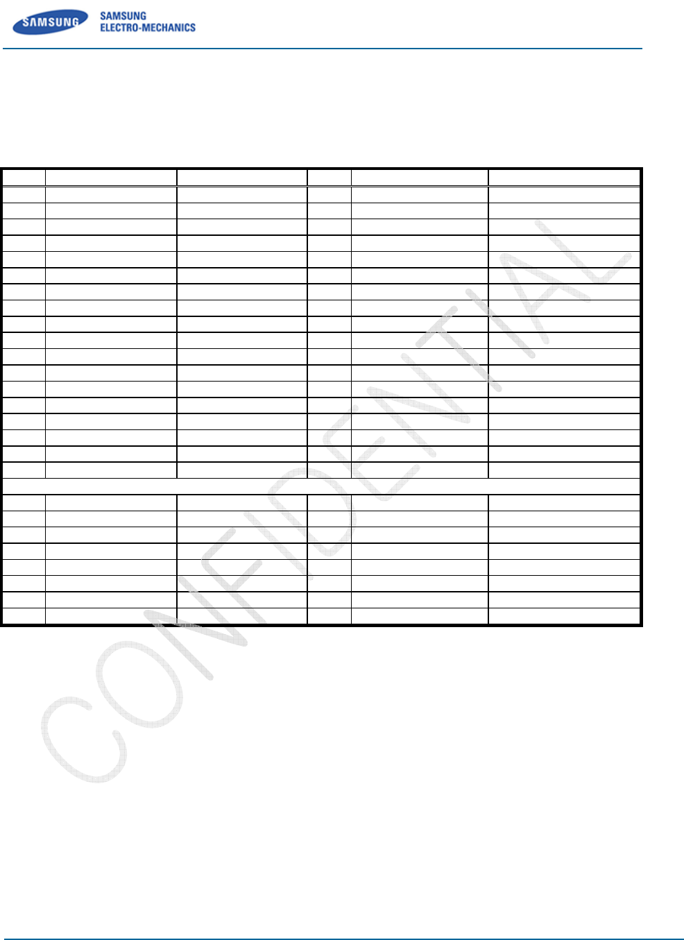
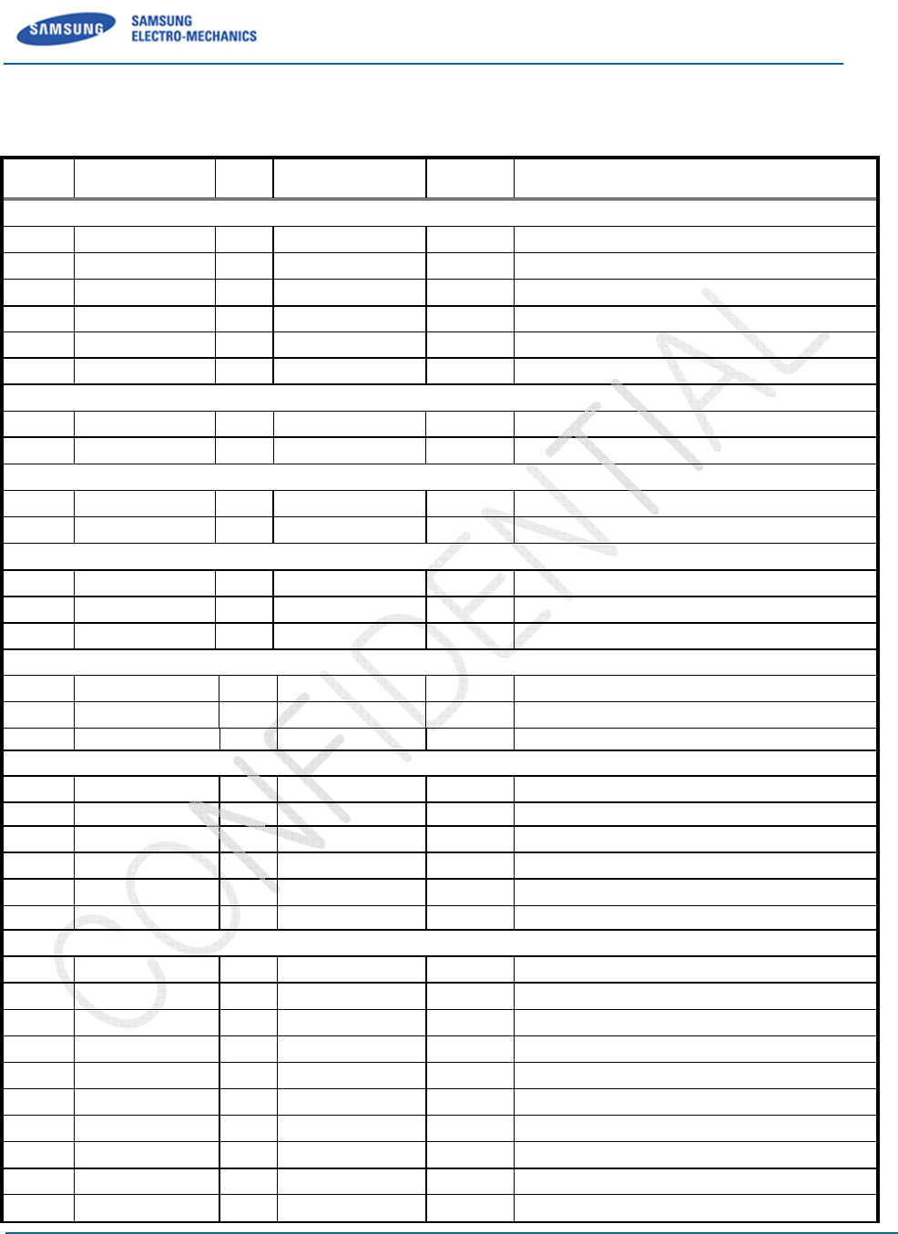
3 Pin
Assignments and
3.1
Pin Assignments
Pin#
Mini Card Standard
SCF
51 Reserved
49 Reserved
47 Reserved
45 Reserved
43 GND
41 +3.3Vaux
39 +3.3Vaux
37 GND
35 GND
33 PETp0
31 PETn0
29 GND
27 GND
25 PERp0
23 PERn0
21 GND
19 UIM_C4
17 UIM_C8
15 GND
13 REFCLK+
11 REFCLK-
9 GND
7 CLKREQ#
5 COEX2
3 COEX1
1 WAKE#
SCF-
V01
Samsung Electro
-Mechanics
Proprietary and Confidential
Assignments and
Descriptions
SCF
-V01 Pin name
Pin#
Mini Card Standard
(JTAG_RST_N) 52 +3.3Vaux
(JTAG_TDI) 50 GND
(JTAG_TDO) 48 +1.5V
(JTAG_TMS) 46 LED_WPAN#
GND 44 LED_WLAN#
+3.3V
42 LED_WWAN#
+3.3V
40 GND
GND 38 USB_D+
GND 36 USB_D-
(JTAG_CLK) 34 GND
(JTAG_RTCK) 32 SMB_DATA
GND 30 SMB_CLK
GND 28 +1.5V
(RXD0) 26 GND
(TXD0) 24 +3.3Vaux
GND 22 PERST#
N.C 20 W_DISABLE#
N.C 18 GND
Mechanical Key
GND 16 UIM_VPP
N.C 14 UIM_RESET
N.C 12 UIM_CLK
GND 10 UIM_DATA
N.C 8 UIM_PWR
N.C 6 1.5V
N.C 4 GND
N.C 2 3.3Vaux
Table 3-1. Pin Assignments
V01
User Manual
Proprietary and Confidential
7/16
SCF-V01 Pin name
+3.3V
GND
N.C
N.C
N.C
LED_WWAN#
GND
USB_D+
USB_D-
GND
N.C
N.C
N.C
GND
+3.3V
RESET_N
W_DISABLE#
GND
N.C
UIM_RESET_N
UIM_CLK
UIM_IO
VDD_UIM
N.C
GND
+3.3V
REV 0.1
Samsung Electro
3.2
Pin Description
Pin# Signal Name Type
JTAG Interface
33 JTAG_CLK I
47 JTAG_TDO O
45 JTAG_TMS I
49 JTAG_TDI I
51 JTAG_RST_N I
31 JTAG_RTCK O
UART Interface
23 TXD0 O
25 RXD0 I
USB Interface
38 USB_D- IO
36 USB_D+ IO
UIM Interface
10 UIM_IO IO
12 UIM_CLK O
14 UIM_RST_N O
GPIOs and Miscellaneous
22 PERST# I
20 W_DISABLE# I
42 LED_WWAN# O
Power Supplies
41 +3.3V I
39 +3.3V I
52 +3.3V I
24 +3.3V I
8 VDD_UIM O
2 +3.3V I
Ground
43 GND -
37 GND -
35 GND -
29 GND -
27 GND -
21 GND -
15 GND -
9 GND -
50 GND -
40 GND -
SCF-
V01
Samsung Electro
-Mechanics
Proprietary and Confidential
Connection to
IC Pin
Power
Domain
Description
CP_TCK (N.C) JTAG Clock
CP_TDO (N.C) Data Out
CP_TMS (N.C) Mode Selec
t
CP_TDI (N.C) Data In
CP_TRST_N (N.C) JTAG Reset
CP_RTCK (N.C)
JTAG Return Clock
CP_UART0_OUT (N.C) UART0
data out
CP_UART0_IN (N.C) UART0
data in
USB_DMN
Inverted USB transceiver data
USB_DPS Non-
inverted USB transceiver data
UIM_IO UIM data input-
output
UIM_CLK UIM clock signal
UIM_RSTN UIM reset signal
PM Reset Functional Reset
GPIO[01] RF Disable
, Active low signal
GPIO[06]
Status indicator via LED device, Active low signal
3.3V Source
3.3V Source
3.3V Source
3.3V Source
UIM power output
3.3V Source
Ground
Ground
Ground
Ground
Ground
- Ground
- Ground
- Ground
- Ground
- Ground
V01
User Manual
Proprietary and Confidential
8/16
t
JTAG Return Clock
data out
data in
Inverted USB transceiver data
inverted USB transceiver data
output
, Active low signal
Status indicator via LED device, Active low signal
UIM power output

REV 0.1
Samsung Electro
34 GND -
26 GND -
18 GND -
4 GND -
Type: I=Input, O=Output, I/O=Bi-
directional
SCF-
V01
Samsung Electro
-Mechanics
Proprietary and Confidential
- Ground
- Ground
- Ground
- Ground
directional
Table 3-2. Pin Descriptions
V01
User Manual
Proprietary and Confidential
9/16
REV 0.1
Samsung Electro
4
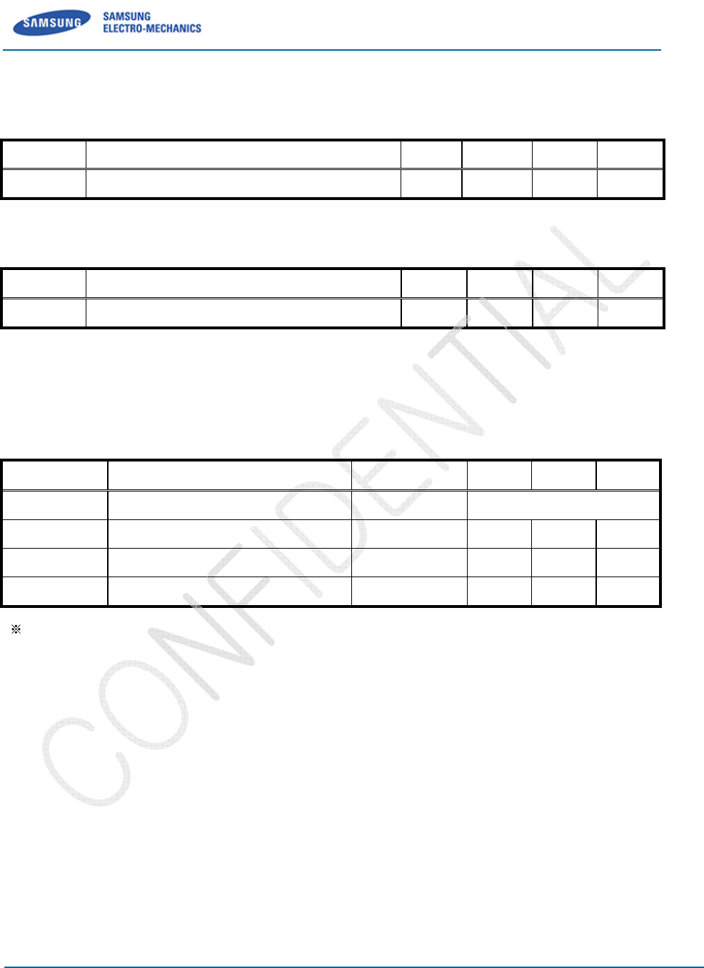
Electrical Characteristics
4.1
DC Characteristics
Symbol
Parameter
+3.3V
Main input supply from battery to switcher
Table
Symbol
Parameter
+3.3 Main input
supply from battery to switcher
Table
4.2
En
vironmental Characteristics
Symbol
Parameter
ESD Electro-
static discharge voltage
To
Operating temperature
Te Extended o
perating temperature
Ts
Storage temperature
Extended operating temperature range is not fully 3GPP2 CDMA specification compliant.
Table
SCF-
V01
Samsung Electro
-Mechanics
Proprietary and Confidential
Electrical Characteristics
DC Characteristics
Parameter
Min
Typ.
Main input supply from battery to switcher
-0.5 -
Table
4-1. Absolute Maximum Ratings
Parameter
Min
Typ.
supply from battery to switcher
3.0 3.
3
Table
4-2. Recommended Operating Conditions
vironmental Characteristics
Parameter
Conditions
Min
static discharge voltage
HBM
Operating temperature
-2
0
perating temperature
-
30
Storage temperature
-4
0
Extended operating temperature range is not fully 3GPP2 CDMA specification compliant.
Table
4-3. Environmental Characteristics
V01
User Manual
Proprietary and Confidential
10/16
Typ.
Max Unit
+4.8 V
Typ.
Max Unit
3
3.6 V
Min
. Max. Unit
Class 1C
0
+60 °C
30
+85 °C
0
+125 °C
Extended operating temperature range is not fully 3GPP2 CDMA specification compliant.
REV 0.1
Samsung Electro
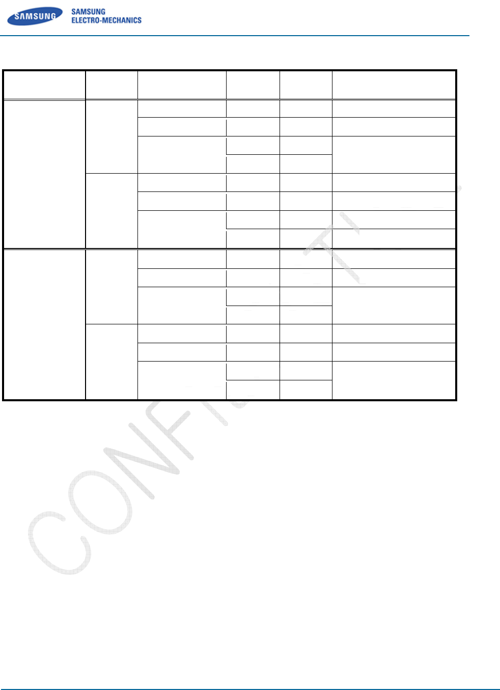
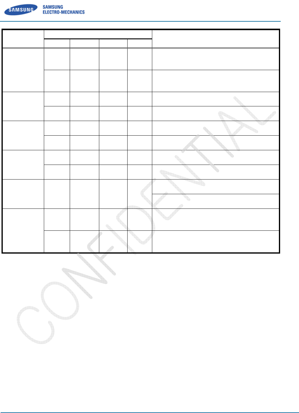
4.3
Power Consumption
Format RF Band
1x_RTT
PCS
Cellular
EVDO
[Rev 0]
PCS
Cellular
SCF-
V01
Samsung Electro
-Mechanics
Proprietary and Confidential
Power Consumption
Mode Current
@ 3.3V
@ Room Temp
Idle Mode Typ 160mA
Min Tx Power Typ 250mA
Cell Power
Tx Max Power
Typ 670mA
Tx Power 23.5
Max 750mA
Idle Mode Typ 160mA
Min Tx Power Typ 220mA
Cell Power
Tx Max Power
Typ 610mA
Tx Power 23.5dBm
Max 650mA
Idle Mode Typ 200mA
Min Tx Power Typ 340mA
Cell Power
Tx Max Power
Typ 900mA
Tx Power 23.5dBm
Max 940mA
Idle Mode Typ 200mA
Min Tx Power Typ 330mA
Cell Power
Tx Max Power
Typ 800mA
Tx Power 23.5dBm
Max 850mA
V01
User Manual
Proprietary and Confidential
11/16
Condition
@ Room Temp
Cell Power
-25dBm
Tx Power 23.5
dBm
Cell Power
-25dBm
Tx Power 23.5dBm
Cell Power
-25dBm
Tx Power 23.5dBm
Cell Power
-25dBm
Tx Power 23.5dBm
REV 0.1
Samsung Electro
5
RF Specifications
All measurements are made under
5.1
Basic performance of RF
Frequency : Band Class0 :
Band Class1 :
Impendence : 50ohm
VSWR : < 3
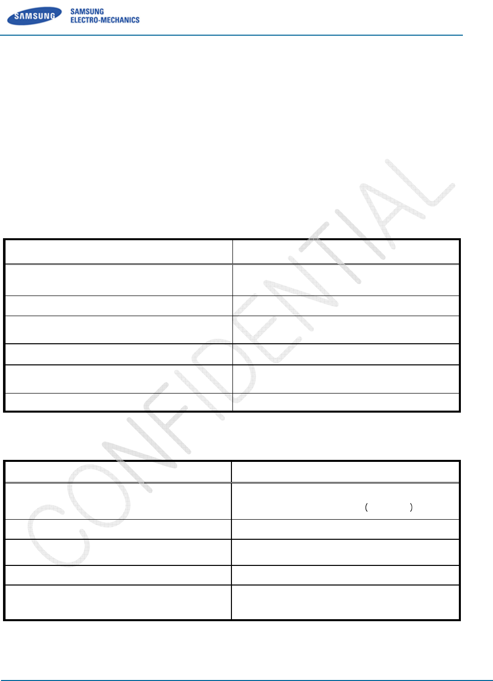
Transmitter Specif
Operating Frequency
Modulation
Conversion Method
Oscillation Method
RF Output Power
Frequency Stability
Receiver Specification
Operating Frequency
Modulation
Conversion Method
Oscillation Method
Receiver Sensitivity
SCF-
V01
Samsung Electro
-Mechanics
Proprietary and Confidential
RF Specifications
All measurements are made under
nominal supply voltage and room
temperature conditions
Basic performance of RF
Specifications
TX:824MHz-849MHz; RX:869MHz-894MHz
TX:1850MHz-1910MHz; RX:1930MHz-1990MHz
Transmitter Specif
ication
Value
Operating Frequency
824MHz ~ 849MHz (Cellular Band)
1850
MHz~1910MHz(PCS Band)
OQPSK/H
Conversion Method
GCT`s intrinsic zero-
IF (intermediate frequency)
& low-
IF radio technology
Oscillation Method
VCTCXO & PLL Synthesizer
RF Output Power
Maximum 0.2W
Minimum 10nW (
Frequency Stability
+/-
300Hz
Table 5-1. Transmitter Specifications
Receiver Specification
Value
Operating Frequency
869MHz ~ 894MHz (Cellular Band)
1930
MHz~1990MHz
OQPSK
/HPSK
Conversion Method
Zero-
IF (intermediate frequency) & low
Oscillation Method
VCTCXO & PLL Synthesizer
Receiver Sensitivity
-104dBm @
FER 0.5%
-105.5dBm @
FER 0.5% for EVDO
Table 5-2. Receiver Specifications
V01
User Manual
Proprietary and Confidential
12/16
temperature conditions
.
Value
824MHz ~ 849MHz (Cellular Band)
MHz~1910MHz(PCS Band)
OQPSK/H
PSK
IF (intermediate frequency)
IF radio technology
VCTCXO & PLL Synthesizer
Maximum 0.2W
Minimum 10nW (
-50dBm)
300Hz
Value
869MHz ~ 894MHz (Cellular Band)
MHz~1990MHz
PCS Band
/HPSK
IF (intermediate frequency) & low
-IF
VCTCXO & PLL Synthesizer
FER 0.5%
for 1X
FER 0.5% for EVDO
REV 0.1
Samsung Electro
ITEM LCL
Typ
Tx Max
Power
23.0 23.
5
23.0 23.
5
Tx Min Power
Rho
0.944
0.944
Frequency
Error
-300
-150
Time Error -1
Rx Sensitivity
(Primary /
Secondary)
Table
SCF-
V01
Samsung Electro
-Mechanics
Proprietary and Confidential
Spec
Test Condition
Typ
UCL Unit
5
24.0 dBm
Cellular Band(824.7MHz,836.52MHz ,
848.41MHz)
Cal Target : 23.7dBm
5
24.0 dBm
PCS Band(1851.25MHz , 1880MHz ,
1908.75MHz)
Cal Target : 23.7dBm
-50 dBm
Cellular Band(824.7MHz,836.52MHz ,
848.41MHz)
-50 dBm
PCS Band(1851.25MHz , 1880MHz ,
1908.75MHz)
1
Cellular Band(824.7MHz,836.52MHz ,
848.41MHz)
1
PCS Band(1851.25MHz , 1880MHz ,
1908.75MHz)
300 Hz
Cellular Band(824.7MHz,836.52MHz ,
848.41MHz)
150 Hz
PCS Band(1851.25MHz , 1880MHz ,
1908.75MHz)
1 us
Cellular Band(824.7MHz,836.52MHz ,
848.41MHz)
PCS Band(1851.25MHz , 1880MHz ,
1908.75MHz)
0.5 %
Cellular Band(869.7MHz,881.52MHz ,
893.31MHz)
Cell Power : -
105dBm , 95% Confidence
0.5 %
PCS Band(1931.25MHz , 1960MHz ,
1988.75MHz)
Cell Power : -
105dBm , 95% Confidence
Table
5-3. RF Conduction Specifications
V01
User Manual
Proprietary and Confidential
13/16
Test Condition
Cellular Band(824.7MHz,836.52MHz ,
PCS Band(1851.25MHz , 1880MHz ,
Cellular Band(824.7MHz,836.52MHz ,
PCS Band(1851.25MHz , 1880MHz ,
Cellular Band(824.7MHz,836.52MHz ,
PCS Band(1851.25MHz , 1880MHz ,
Cellular Band(824.7MHz,836.52MHz ,
PCS Band(1851.25MHz , 1880MHz ,
Cellular Band(824.7MHz,836.52MHz ,
PCS Band(1851.25MHz , 1880MHz ,
Cellular Band(869.7MHz,881.52MHz ,
105dBm , 95% Confidence
PCS Band(1931.25MHz , 1960MHz ,
105dBm , 95% Confidence
REV 0.1
Samsung Electro
6 Label
Information
6.1
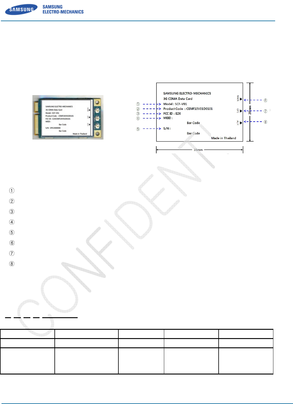
Module Label
The Label contains Model Name, Product Code, FCC ID, MEID and Serial Number.
Figure
[Information]
Model : SCF-V01
Product Code
: CEMF10V01D0101
FCC ID : E2XSCF-V01
MEID : Mobile Equipment
Id
S/N : Serial Number
MAIN
: Main Antenna connection
GPS
: GPS Antenna connection
AUX : Diversity
Antenna connection
6.1.1
S/N(Serial Number)
Ex)
S Q G B 000001
S
Q
Company
S: Samsung
Custom Model
Q :
CEMF10V01D0101
Table
SCF-
V01
Samsung Electro
-Mechanics
Proprietary and Confidential
Information
The Label contains Model Name, Product Code, FCC ID, MEID and Serial Number.
Figure
6-1. Label Information
: CEMF10V01D0101
Id
entifier
: Main Antenna connection
: GPS Antenna connection
Antenna connection
S/N(Serial Number)
Q
G B
Custom Model
CEMF10V01D0101
Year
F:2011
G:2012
Month
1~9:Jan~SEP
A:OCT, B:Nov,
C:Dec
Table
6-1. Serial Number Information
V01
User Manual
Proprietary and Confidential
14/16
The Label contains Model Name, Product Code, FCC ID, MEID and Serial Number.
000001
000001~FFFFFF
Serial No(Hex)
REV 0.1
Samsung Electro
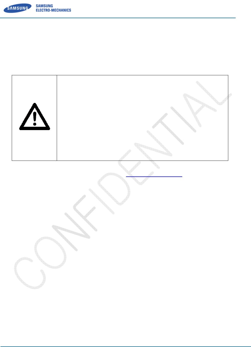
7
Safety Information
7.1
Certification
FCC ID : E2XSCF-V01
Warning: Exposure to Radio Frequency Radiation The radiated
output power of this device is far below the FCC radio frequency
exposure limits. Nevertheless, the device should be used in such a
manner that the potential for human co
is minimized. In order to avoid the possibility of exceeding the FCC
radio frequency exposure limits, human proximity to the antenna
should not be less than 20 cm during normal operation. The gain of
the antenna for
must not exceed
Can be found under the Display Grant section of
FCC ID: E2XSCF-V01
FCC Compliance Information
Th
is device complies with Part 15 of FCC Rules.
Operation is subject to the following two conditions:
(1) This device may not cause harmful interference, and
(2) This device must accept any interference received.
Including interference that may cause u
7.2
Caution
Modifications not expressly approved by the party responsible for compliance could void the user
authority to operate the equipment.
SCF-
V01
Samsung Electro
-Mechanics
Proprietary and Confidential
Safety Information
Warning: Exposure to Radio Frequency Radiation The radiated
output power of this device is far below the FCC radio frequency
exposure limits. Nevertheless, the device should be used in such a
manner that the potential for human co
ntact during normal operation
is minimized. In order to avoid the possibility of exceeding the FCC
radio frequency exposure limits, human proximity to the antenna
should not be less than 20 cm during normal operation. The gain of
the antenna for
Cellular band must not exceed 2
dBi
must not exceed
2 dBi.
Can be found under the Display Grant section of
www.fcc.gov/oet/ea/fccid
FCC Compliance Information
is device complies with Part 15 of FCC Rules.
Operation is subject to the following two conditions:
(1) This device may not cause harmful interference, and
(2) This device must accept any interference received.
Including interference that may cause u
ndesired operation.
Modifications not expressly approved by the party responsible for compliance could void the user
authority to operate the equipment.
V01
User Manual
Proprietary and Confidential
15/16
Warning: Exposure to Radio Frequency Radiation The radiated
output power of this device is far below the FCC radio frequency
exposure limits. Nevertheless, the device should be used in such a
ntact during normal operation
is minimized. In order to avoid the possibility of exceeding the FCC
radio frequency exposure limits, human proximity to the antenna
should not be less than 20 cm during normal operation. The gain of
dBi
and PCS band
www.fcc.gov/oet/ea/fccid
after searching on
Modifications not expressly approved by the party responsible for compliance could void the user
’s

REV 0.1
Samsung Electro
Revision History
Revision Date
Descriptions
0
.0
20
1
2
-
0
2
-
10
Initial Release
0.1
2012
-
06
-
18
Add Label Information, Add Safety Information
SCF-
V01
Samsung Electro
-Mechanics
Proprietary and Confidential
Descriptions
Initial Release
Add Label Information, Add Safety Information
V01
User Manual
Proprietary and Confidential
16/16

REV 0.1
Samsung Electro-Mechanics Proprietary and Confidential
8/8
M & SOFT AMERICA MAP CENTER
TEL : 888-757-0010
WEBSITE : www.mapnsoft.com
MAP DATABASE HOTLINE
This equipment has been tested and found to comply with the limits for a Class A digital device, pursuant to part 15 of the FCC Rules.
These limits are designed to provide reasonable protection against harmful interference in a residential installation. This equipment
generates, uses and can radiate radio frequency energy and, if not installed and used in accordance with the instructions, may cause
harmful interference to radio communications. However, there is no guarantee that interference will not occur in a particular
installation. If this equipment does cause harmful interference to radio or television reception, which can be determined by turning the
equipment off and on, the user is encouraged to try to correct the interference by one or more of the following measures:
ˍ Reorient or relocate the receiving antenna.
ˍ Increase the separation between the equipment and receiver.
ˍ Connect the equipment into an outlet on a circuit different from that to which the receiver is connected.
ˍ Consult the dealer or an experienced radio/TV technician for help.
Caution: Any changes or modifications to this device not explicitly approved by manufacturer could void your authority to operate this
equipment.
This device complies with part 15 of the FCC Rules. Operation is subject to the following two conditions: (1) This device may not
cause harmful interference, and (2) this device must accept any interference received, including interference that may cause undesired
operation.
,&:DUQLQJ
7KLVGHYLFHFRPSOLHVZLWK,QGXVWU\&DQDGDOLFHQFHH[HPSW566VWDQGDUGV
2SHUDWLRQLVVXEMHFWWRWKHIROORZLQJWZRFRQGLWLRQVWKLVGHYLFHPD\QRWFDXVHLQWHUIHUHQFHDQG
WKLVGHYLFHPXVWDFFHSWDQ\LQWHUIHUHQFHLQFOXGLQJLQWHUIHUHQFHWKDWPD\FDXVHXQGHVLUHGRSHUDWLRQRIWKHGHYLFH
/HSUpVHQWDSSDUHLOHVWFRQIRUPHDX[&15G,QGXVWULH&DQDGDDSSOLFDEOHVDX[DSSDUHLOVUDGLRH[HPSWVGHOLFHQFH
/H[SORLWDWLRQHVWDXWRULVpHDX[GHX[FRQGLWLRQVVXLYDQWHVODSSDUHLOQHGRLWSDVSURGXLUHGHEURXLOODJHHW
OXWLOLVDWHXUGHODSSDUHLOGRLWDFFHSWHUWRXWEURXLOODJHUDGLRpOHFWULTXHVXEL
PrPHVLOHEURXLOODJHHVWVXVFHSWLEOHGHQFRPSURPHWWUHOHIRQFWLRQQHPHQW
This equipment complies with FCC radiation exposure limits set forth for an uncontrolled environment.
This equipment should be installed and operated with minimum 20 cm between the radiator and your body.
This transmitter must not be collocated or operating in conjunction with any other antenna or transmitter unless authorized to do so by the FCC.
This equipment has been tested and found to comply with the limits for a Class A digital device, pursuant to part 15 of the FCC Rules.
These limits are designed to provide reasonable protection against harmful interference in a residential installation. This equipment
generates, uses and can radiate radio frequency energy and, if not installed and used in accordance with the instructions, may cause
harmful interference to radio communications. However, there is no guarantee that interference will not occur in a particular
installation. If this equipment does cause harmful interference to radio or television reception, which can be determined by turning the
equipment off and on, the user is encouraged to try to correct the interference by one or more of the following measures:
ˍ Reorient or relocate the receiving antenna.
ˍ Increase the separation between the equipment and receiver.
ˍ Connect the equipment into an outlet on a circuit different from that to which the receiver is connected.
ˍ Consult the dealer or an experienced radio/TV technician for help.
Caution: Any changes or modifications to this device not explicitly approved by manufacturer could void your authority to operate this
equipment.
d your body.
)RUODEHOUHTXLUHPHQWZKHQWUDQVPLWWHUPRGXOHLVLQVWDOOHGLQDKRVWWKHKRVWVKDOOKDYHDQDGGLWLRQDOSHUPDQHQWODEHOUHIHUULQJWRWKHHQFORVHGPRGXOH³&RQWDLQV7UDQVPLWWHU0RGXOH)&&,'%(-7:)0%'´)RUODEHOUHTXLUHPHQWZKHQWUDQVPLWWHUPRGXOHLVLQVWDOOHGLQDKRVWWKHKRVWVKDOOKDYHDQDGGLWLRQDOSHUPDQHQWODEHOUHIHUULQJWRWKHHQFORVHGPRGXOH³&RQWDLQV7UDQVPLWWHU0RGXOH)&&,'%(-7:)0%'´T7KLVUDGLRFDQQRWEHLQVWDOOHGLQKRVWZKHUHFRORFDWHGRURSHUDWLQJLQFRQMXQFWLRQZLWKDQ\RWKHUDQWHQQDRUWUDQVPLWWHUhis transmitter must not be collocated or operating in conjunction with any other antenna or transmitter unless authorized to do so by the FCC.
G
G
For label requirement when transmitter module is installed in a host,
the host shall have an additional permanent label referring to the enclosed module
“Contains Transmitter Module FCC ID: lYSCF-V01
Samsung Electro-Mechanics Co., Ltd. Proprietary
SCF-V01
ETS(Engineer Test Software) User Manual
REV 0
Steve Heo, Software Application Engineer
Software Part
WS Development Team
Samsung Electro-Mechanics
2012-06-28
Background & Summary
This document describes how to use ETS.
© 2012 Samsung Electro-Mechanics. All rights reserved
The names of actual companies and products mentioned
herein may be the trademarks of their respective owners.
This document is subject to change without notice.
No part of this document may be reproduced, stored in a
retrieval system, or transmitted in any form or by any
means without the express written consent of Samsung
Electro-Mechanics.

Samsung Electro-Mechanics Co., Ltd. Proprietary
REV 0
Samsung Electro-Mechanics Co., Ltd.
Proprietary Page ii
Table of Contents
1 INTRODUCTION ................................................................................................................. 3
1.1 A
CRONYMS
....................................................................................................................... 3
1.2 L
IST OF
T
ERMS
.................................................................................................................. 3
2 SETUP AND QUICK START .................................................................................................. 4
2.1 S
YSTEM
R
EQUIREMENTS
....................................................................................................... 4
2.2 I
NSTALLING AND
R
EMOVING
................................................................................................... 5
2.3 R
UNNING
ETS
FOR THE
F
IRST
T
IME
......................................................................................... 7
2.4 H
OW TO
E
XIT
.................................................................................................................... 7
2.5 O
PENING AND
S
AVING
C
ONFIGURATION
F
ILES
............................................................................. 7
2.6 ETS
D
EFINES
.................................................................................................................. 10
2.7 ETS
O
PTIONS
.................................................................................................................. 11
3 IDLE MODE ....................................................................................................................... 12
3.1 RSSI
FOR
CDMA ............................................................................................................. 12
3.2 O
VERHEAD
P
AGING
S
PY
...................................................................................................... 12
3.3 R
EGISTRATION
M
ESSAGE
S
PY
............................................................................................... 13
3.4 T
X
PWR
D
ETECT
M
EASUREMENTS
S
PY
.................................................................................... 13
3.5 HWD
F
REQUENCY
C
HANNEL
T
RACE
........................................................................................ 14
3.6 P
ILOT
S
TRENGTH
S
PY
........................................................................................................ 15
4 IN-CALL MODE.................................................................................................................. 16
4.1 V
OICE
C
ALL
I
NITIATE
......................................................................................................... 16
4.2 V
OICE
C
ALL
A
NSWER
......................................................................................................... 17
4.3 V
OICE
C
ALL
H
ANG
U
P
........................................................................................................ 18
4.4 V
OICE
C
ALL
C
ONFIGURATION
............................................................................................... 18
4.5 R
ADIO
C
ONTROL
.............................................................................................................. 20
5 TEST/DEBUG CAPABILITY ................................................................................................ 21
5.1 B
ASICS
.......................................................................................................................... 21
5.2 T
EST
M
ODES
................................................................................................................... 24
5.3 RF
I
NTERFACE AND
C
ONTROL
............................................................................................... 29
5.4 SMS ............................................................................................................................. 41
5.5 D
ATABASE
U
PLOAD
/D
OWNLOAD
............................................................................................ 42
5.6 S
OFTWARE
O
PERATION
S
TATUS
............................................................................................ 56
5.7 CBP
H
ARDWARE
............................................................................................................... 66
6 UTILITIES ......................................................................................................................... 67
6.1 V
IRTUAL
MMI ................................................................................................................. 67
6.2 S
CRIPT
U
TILITY
................................................................................................................ 67
REVISION HISTORY ................................................................................................................ 74

Samsung Electro-Mechanics Co., Ltd. Proprietary
REV 0
Samsung Electro-Mechanics Co., Ltd.
Proprietary Page 3
1 Introduction
This document provides high-level functional descriptions of the CBP 5.X CDMA Baseband Processor
digital hardware subsystems.
1.1 Acronyms
ADC Analog-to-Digital Converter
AMPS Advanced Mobile Phone System
APB ARM Peripheral Bus
CBP5.X CDMA Baseband Processor version 4.1/5.0/5.1
CP Control Processor
DAI Digital Audio Interface
DAC Digital-to-Analog Converter
DSPM Digital Signal Processor - Modem
DSPV Digital Signal Processor – Voice
DUT Device Under Test
EBI External Bus Interface
ICE In-Circuit Emulator
MMI Man-Machine Interface
PCG Power Control Group
PLL Phase Locked Loop
PWM Pulse-Width Modulator
RTOS Real-Time Operating System
SAT Supervisory Audio Tones
SPI Serial Programming Interface
ST Signaling Tone
THRE Transmitter Holding Register Empty
UART Universal Asynchronous Receiver/Transmitter
UIM User Identity Module
WBD Wideband Data
1.2 List of Terms
Table 1 contains a list of terms and abbreviations used in this section.
Samsung Electro-Mechanics Co., Ltd. Proprietary
REV 0
Samsung Electro-Mechanics Co., Ltd.
Proprietary Page 4
Table 1 - External Interface Pin Attributes
Type Description
pu
1
Internal pull-up
pd
2
Internal pull-down
ldrv1 CMOS, low drive strength (1ma)
ldrv2 CMOS, low drive strength (2ma)
mdrv CMOS, medium drive strength (4ma)
hdrv CMOS, high drive strength (8ma)
_N Indicates an active low signal
z Tri-state
od Open-drain
vanlg Input or output with analog voltage levels
dvdd_c Digital VDD to core cells (1.8V)
dvss_c Digital VSS to core cells.
dvdd_r Digital VDD to pad ring (3V)
dvss_r Digital VSS to pad ring
avdd Analog VDD (3V)
avss Analog VSS
1
Internal pull-up resistors are non-linear elements; they have a resistance of about 80 K at
operating conditions of nominal process, 25
o
C and 3 V I/O supply voltage. They exhibit 140 K at
operating conditions of WC process, 125
o
C junction and 2.85 V I/O supply and 42 K at
conditions of BC process, 0
o
C and 3.15 V supply voltage.
2
Internal pull-down resistors: The same conditions apply as listed above for internal pull-up
resistors.
Table 2 - Reset Legend
Type Description
Z Tri-State
H Tri-State with Pull-Up
L Tri-State with Pull-Down
1 CMOS High
0 CMOS Low
X Unknown
2 Setup and Quick Start
2.1 System Requirements
The following are the minimum requirements for running ETS:
Operating System: Windows 2000/XP or later

Samsung Electro-Mechanics Co., Ltd. Proprietary
REV 0
Samsung Electro-Mechanics Co., Ltd.
Proprietary Page 5
Memory: At least 128 MB of RAM
Processor: Pentium II or better
2.2 Installing and Removing
2.2.1 Installing ETS
VIA Telecom delivers the installation program,
“ETS.exe”
, as part of the software release package. VIA
Telecom strongly recommends installing ETS in the default directory as the installing shell indicated.
The VIA Telecom software releases are typically numbered “rX.Y.Z” where:
X = Major Release Number
Y = Minor Release Number
Z = Patch to Minor Release
The VIA Telecom complete software package contains:
a. The VIA Telecom CP code, which executes on
the ARM7TDMI-S™ processor embedded in the CBP5.X chip.
b. An “.img” Image file, which contains code or code patches that will run on the DSPM and DSPV
embedded Oak processors.
c. The “ETS.exe” and “ETS_Config_x.exe” package, which installs ETS.
Example
Assume that the VIA Telecom software release is: r6.0.6.
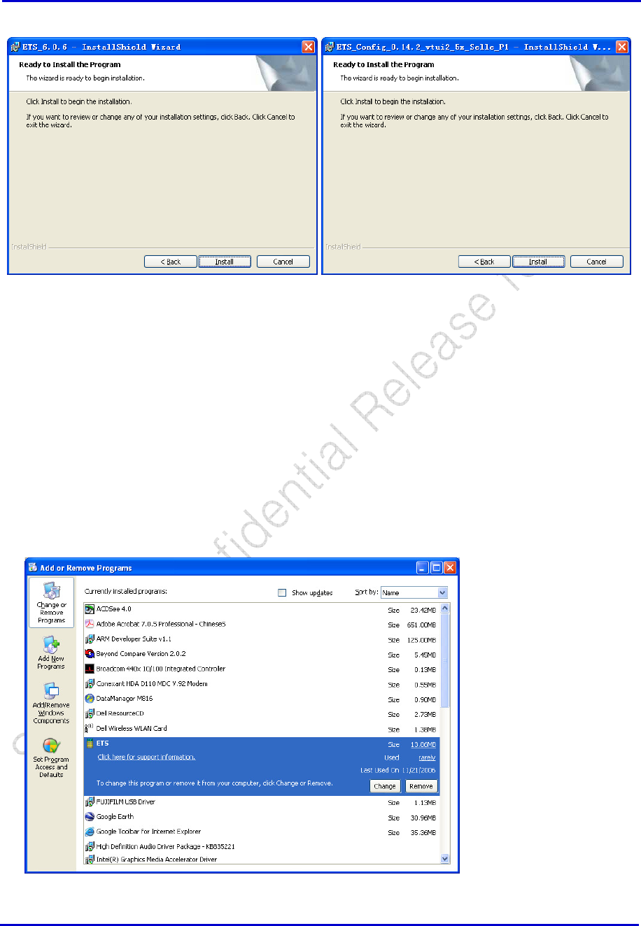
1. The ETS installation program would be: <Customer Path>\PCTools\ets\ETS_6.0.6.exe and
ETS_Config_0.14.2_vtui2_5x.
2. Run ETS_6.0.6.exe and ETS_Config_0.14.2_vtui2_5x . For this example, ETS is installed in
"C:\Program Files\VIA Telecom\VTC-ETS\", ETS_Config is in “C:\Program Files\VIA
Telecom\ETS_Config\".
Samsung Electro-Mechanics Co., Ltd. Proprietary
REV 0
Samsung Electro-Mechanics Co., Ltd.
Proprietary Page 6
3. For other items which will meet in installing process, use default setting is fine. Since from now on,
all of CBP5.X reference software will use same ETS.exe, you NEED NOT pay additional attention to
associate version number between the software release and ETS.
2.2.2 Removing ETS
Use the standard Windows method to remove (uninstall) software.
1. Go to the Control Panel and select Add or Remove Programs.
2. Select ETS and click the Add/Remove button. Follow the standard procedure for uninstalling
Windows-based software.
Samsung Electro-Mechanics Co., Ltd. Proprietary
REV 0
Samsung Electro-Mechanics Co., Ltd.
Proprietary Page 7
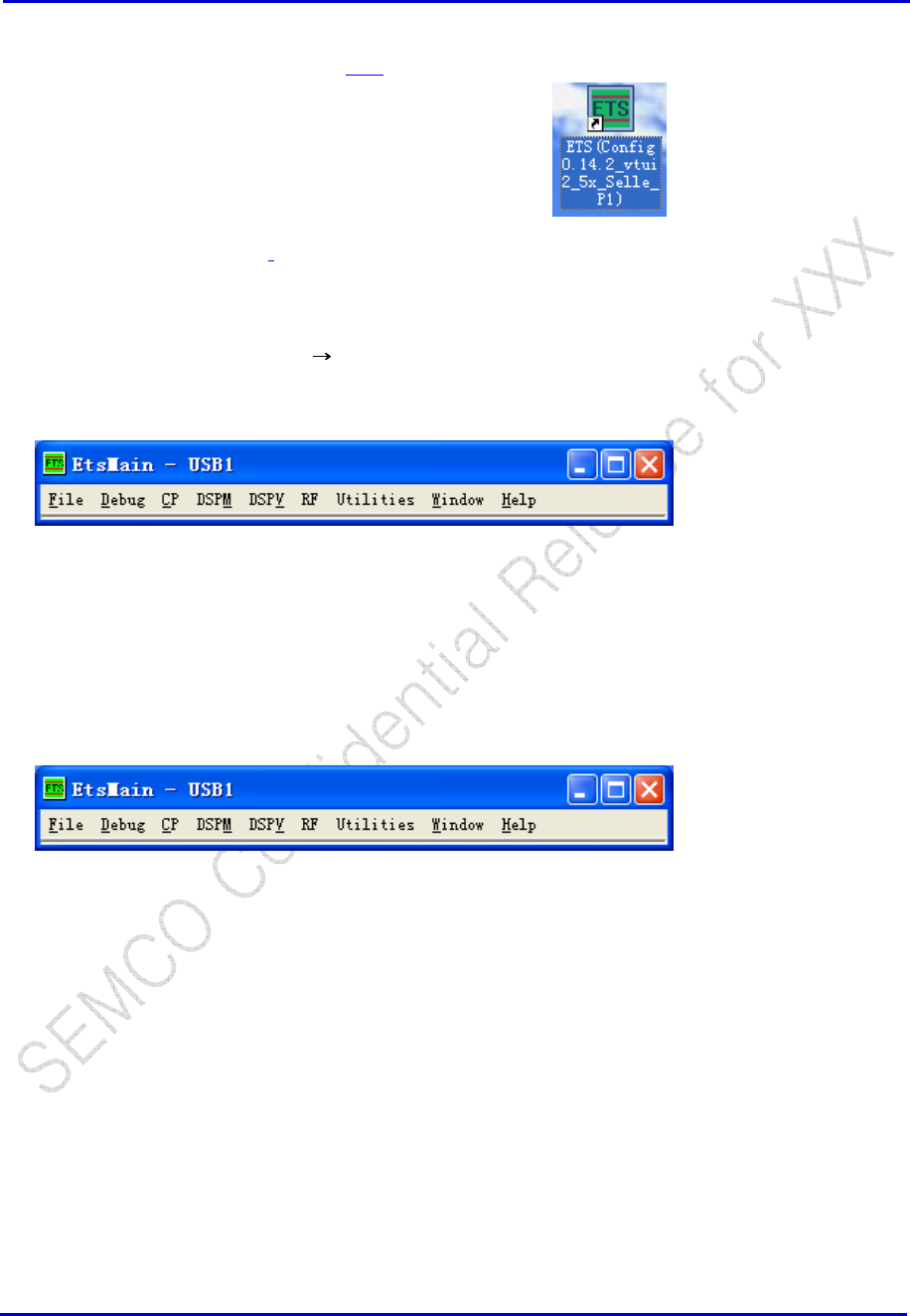
2.3 Running ETS for the First Time
Continuing with the example in Section 2.21, start ETS by selecting:
Windows Desktop →ETS(Config 0.14.2_vtui2_5x_Selle_P1):
Now follow the steps in Section 2.5.1.
2.4 How to Exit
1. From the ETS menu, select File Exit.
See Section 2.5.2 for details on how to save the ETS configuration when exiting.
2.5 Opening and Saving Configuration Files
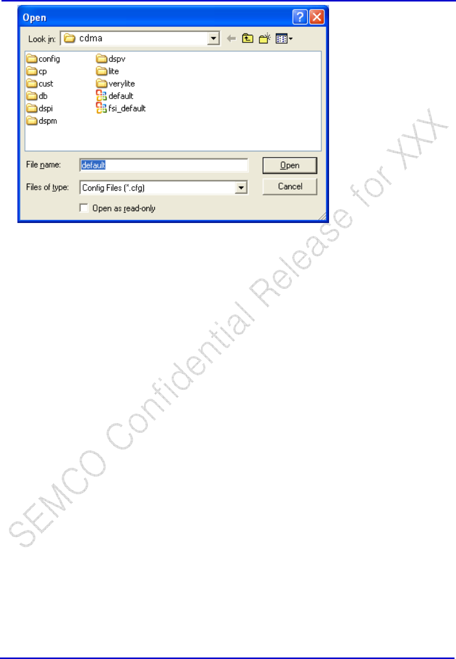
2.5.1 Opening Configuration Files
1. From the ETS menu, select File → Open...
2. Continuing with the
Example
of Section 2.2.1, in the Window below select the Path:
C:\Program Files\VIA Telecom\ETS_Config\0.14.2_vtui2_5x_Selle_P1\config\cdma and
then select the file default.cfg
Samsung Electro-Mechanics Co., Ltd. Proprietary
REV 0
Samsung Electro-Mechanics Co., Ltd.
Proprietary Page 8
Samsung Electro-Mechanics Co., Ltd. Proprietary
REV 0
Samsung Electro-Mechanics Co., Ltd.
Proprietary Page 9
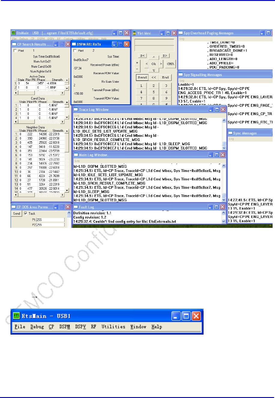
3. After opening default.cfg you should see a screen, which looks similar to the picture below. This
screen has all the standard ETS sub-windows which are typically used at VIA Telecom.
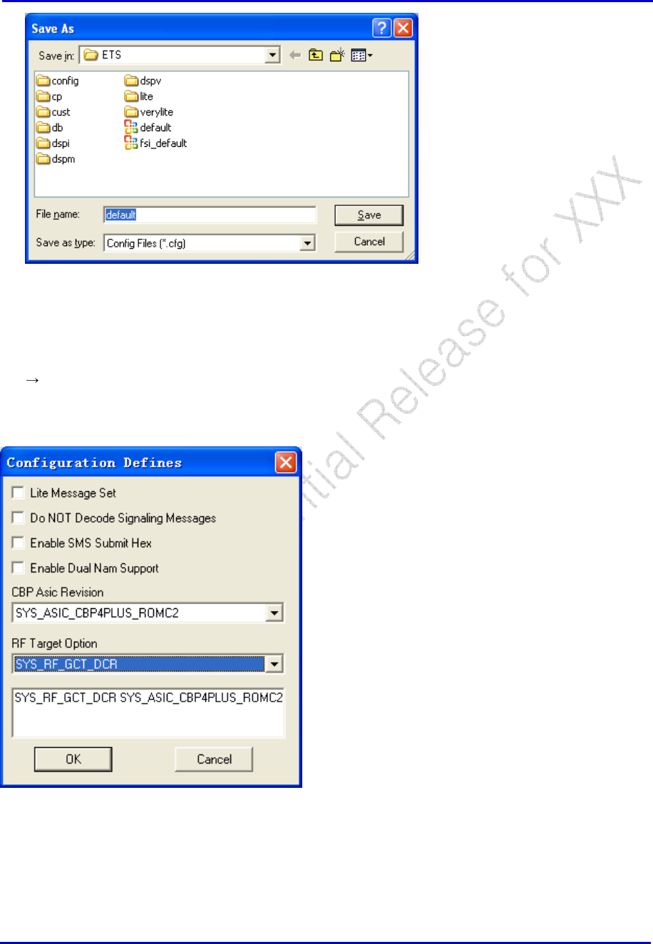
2.5.2 Saving Configuration Files
1. If you have used any special ETS commands during your present session which you’d like to use in a
future session then you can explicitly save the present configuration by using the ETS Main Menu
command:
File Save As
2. Enter the name and path for your configuration file in the dialog box below, or you can choose to
overwrite the present configuration file (typically, “default.cfg”).
Samsung Electro-Mechanics Co., Ltd. Proprietary
REV 0
Samsung Electro-Mechanics Co., Ltd.
Proprietary Page 10
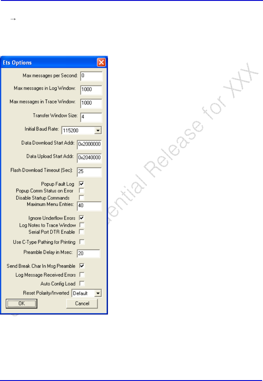
2.6 ETS Defines
File Defines
ETS allows the user to configure the tool for various standard definitions:
Note:
1. This defines must be configured correct as the target HW you using. Else it will case some UN-expect
error. If you don’t sure which option you should select, call VIA application engineer for help.
2. After you changed the definition, should close and restart ETS to make the effort available.
Samsung Electro-Mechanics Co., Ltd. Proprietary
REV 0
Samsung Electro-Mechanics Co., Ltd.
Proprietary Page 11
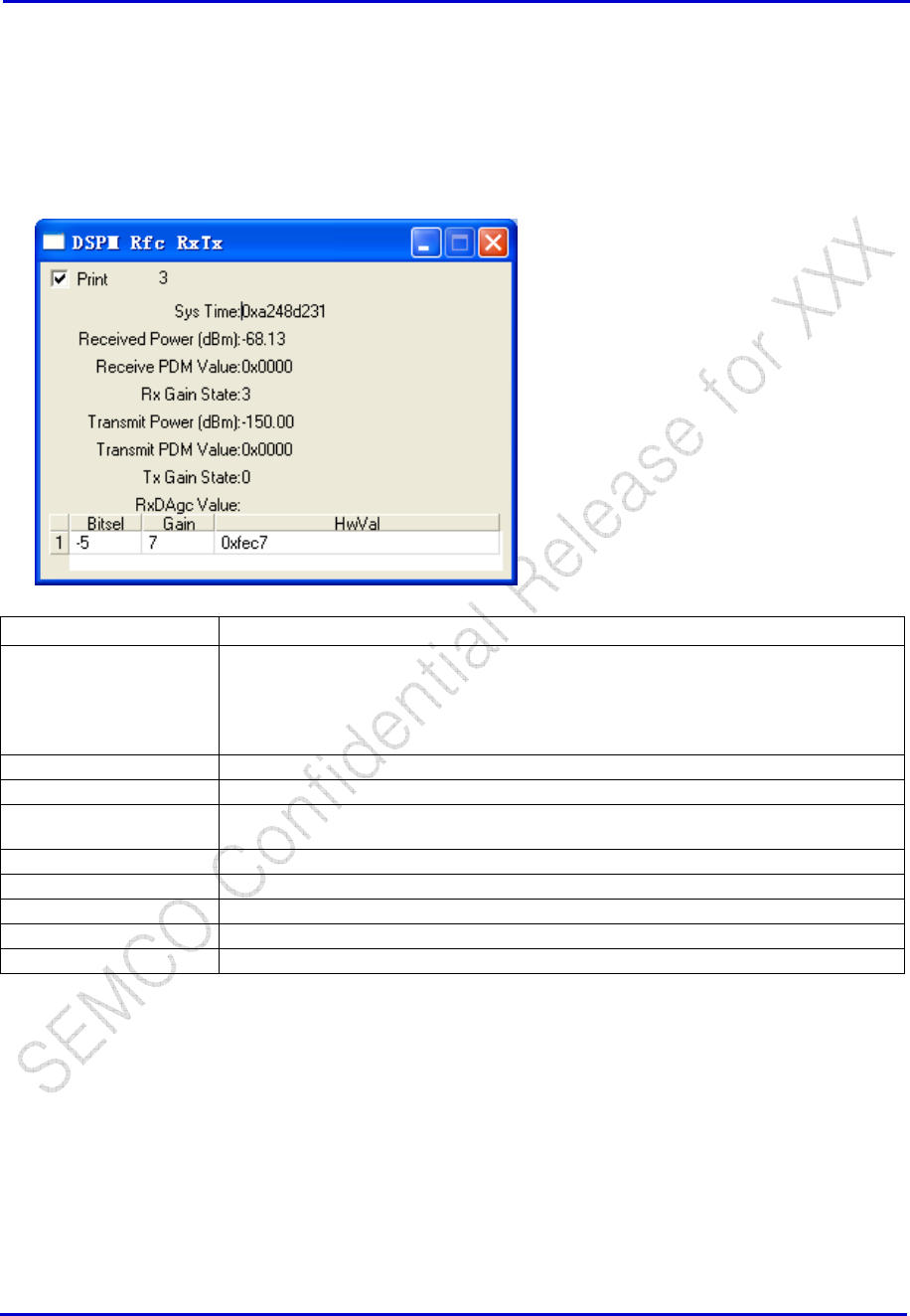
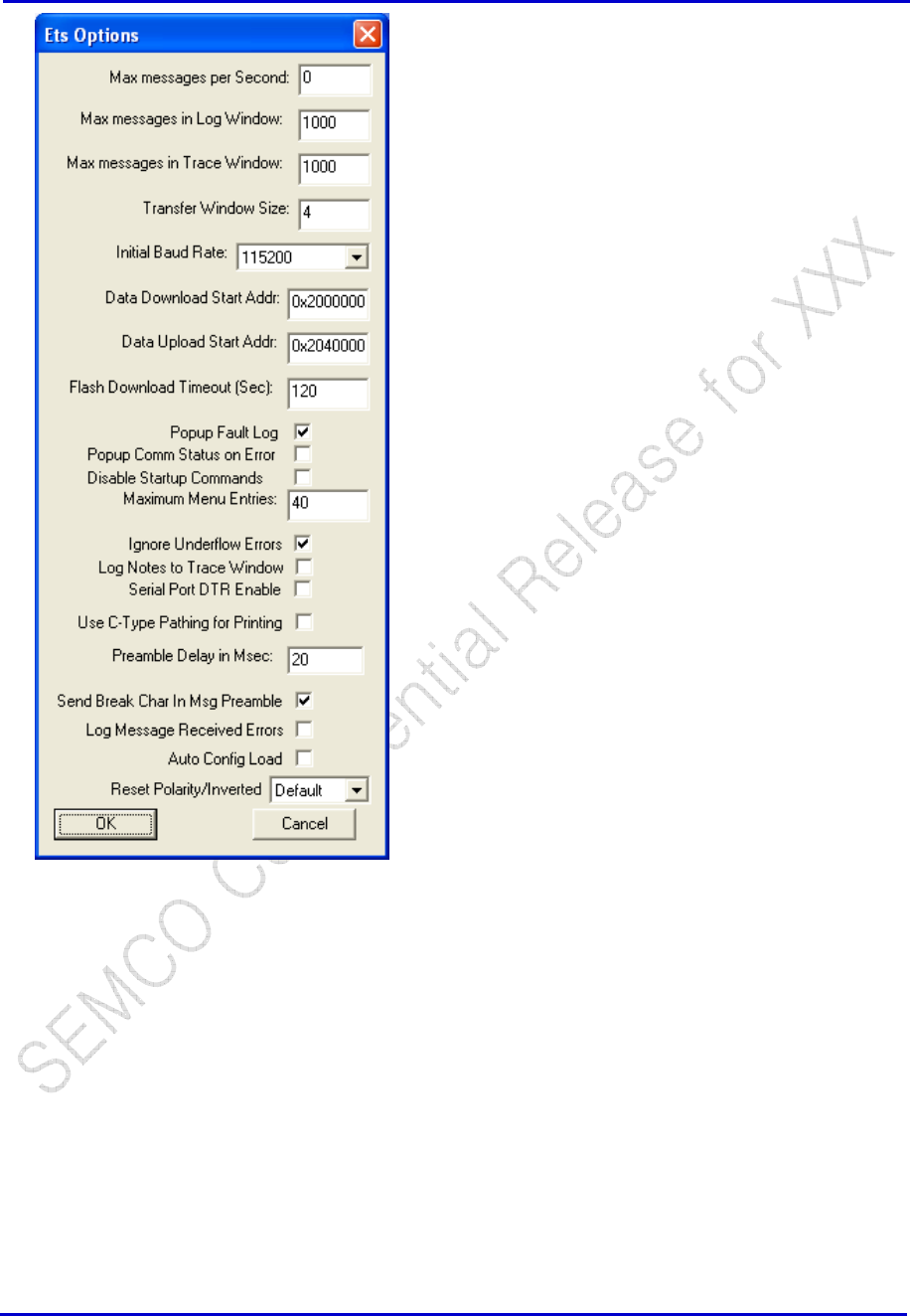
2.7 ETS Options
File Options
There are some parameters you can modify, the value depend on the CP request. Special for Flash
Download Timeout (Sec), we recommend you adjust it longer than the total CP erase time (the lager
CP size is, the longer erase time is). 200s is the typically value VIA internal used.
Samsung Electro-Mechanics Co., Ltd. Proprietary
REV 0
Samsung Electro-Mechanics Co., Ltd.
Proprietary Page 12
3 Idle Mode
3.1 RSSI for CDMA
CDMA: DSPM → Spy → RFC → DSPM Rfc RxTx
Usually this window is opened from loading the “default.cfg” configuration file.
Window Entries Definition
Print If checked, the window will be printed onto the main log as a trace:
15:17:28.8> ETS, Id=DSPM Spy, SpyId=DSPM Rfc RxTx, Sys Time=0xa248d231,
Received Power (dBm)=-68.13, Receive PDM Value=0x0000, Rx Gain State=3,
Transmit Power (dBm)=-150.00, Transmit PDM Value=0x0000, Tx Gain State=0,
Bitsel=-5, Gain=7, HwVal=0xfec7
Sys Time Recorded system time for reference purposes.
Received Power (dBm) Received power from the BS interpreted by the MS.
Receive PDM Value Received power from the BS interpreted by the MS in PDM. This area used for
superhet solution.
Rx Gain State Gain state that the MS receiver is in.
Transmit Power (dBm) Transmit power to the BS interpreted by the MS in dBm.
Transmit PDM Value Transmit power to the BS interpreted by the MS in PDM.
Tx Gain State Gain state that the MS transmitter is in.
RxDAgc Value Received power from the BS interpreted by the MS, this area used for DCR solution.
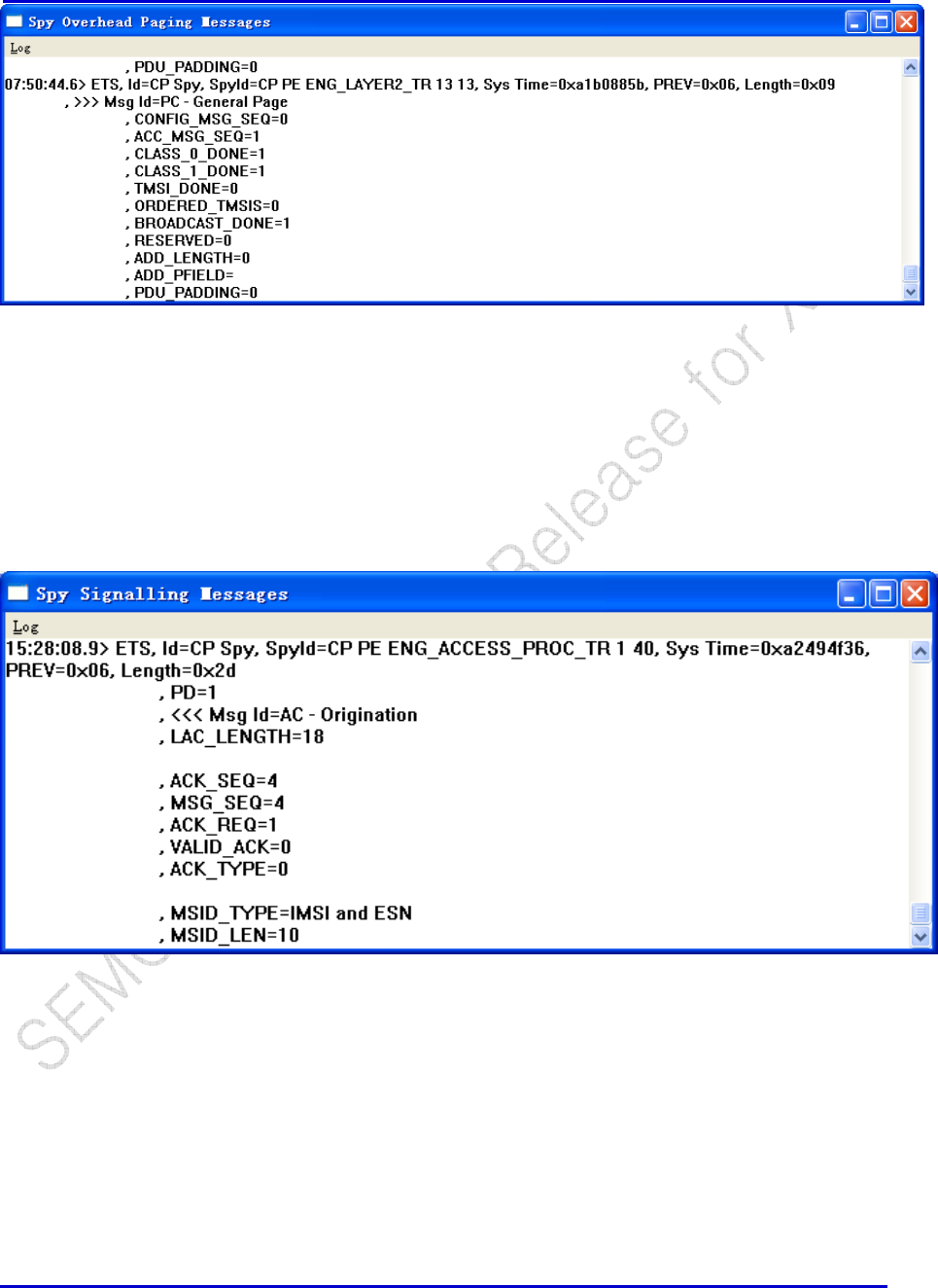
3.2 Overhead Paging Spy
CP → SPY → PS → Call Proc → Engine → Eng_Layer2_TR → CP PE ENG_LAYER2_TR 13 13 (for
CDMA)
The spy is enabled automatically once the “default.cfg” is loaded. This spy displays all CDMA overhead
paging messages broadcast from the base station.
Samsung Electro-Mechanics Co., Ltd. Proprietary
REV 0
Samsung Electro-Mechanics Co., Ltd.
Proprietary Page 13
3.3 Registration Message Spy
CP → SPY → PS → Call Proc → Engine → ENG_ACCESS_PROC_TR → CP
ENG_ACCESS_PROC_TR 1 40
The spy is enabled automatically once the “default.cfg” is loaded. This spy displays all messages from
mobile to the base station during idle mode, through access channel.
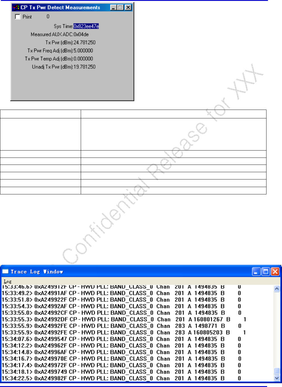
3.4 Tx PWR Detect Measurements Spy
CP → Spy → HWD → CP Tx Pwr Detect Measurements
This spy only works in the following conditions:
Tx Pwr Detect cal tables “Tx Pwr Detect” and “Tx Pwr Det Freq Adj” and “Det Temp Adj” are
populated.
Mobile is transmitting beyond the threshold that AUX ADC actually kicks in (typically +15dBm or
above)
Samsung Electro-Mechanics Co., Ltd. Proprietary
REV 0
Samsung Electro-Mechanics Co., Ltd.
Proprietary Page 14
Window Selections Definition
Print If checked, the window will be printed onto the main log as a trace:
10:40:50.1> ETS, Id=CP Spy, SpyId=CP Tx Pwr Detect Measurements, Sys
Time=0x823ee47e, Measured AUX ADC=0x04de, Tx Pwr (dBm)=-24.781250,
Tx Pwr Freq Adj (dBm)=5.000000, Tx Pwr Temp Adj (dBm)=0.000000, Unadj
Tx Pwr (dBm)=19.781250
Sys Time Display system time for reference.
Measured AUX ADC Reads AUX ADC value of Tx Pwr Detect.
Tx Pwr (dBm) Displays mobile’s final transmitting power in dBm.
Tx Pwr Freq Adj (dBm) Display corresponding Adj read from cal table.
Tx Pwr Temp Adj (dBm) Display corresponding Adj read from cal table.
Unadj Tx Pwr (dBm) Display the unadjusted Tx power transmitted.
3.5 HWD Frequency Channel Trace
CP → Trace → HWD → CP Freq Channel
This trace is enabled automatically once the “default.cfg” is loaded. This trace displays the channels that
the mobile searches in the Trace Log Window when the protocol stack is on:
Samsung Electro-Mechanics Co., Ltd. Proprietary
REV 0
Samsung Electro-Mechanics Co., Ltd.
Proprietary Page 15
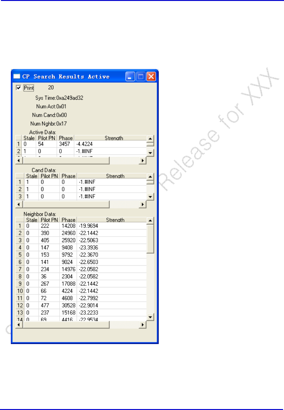
3.6 Pilot Strength Spy
CP → Spy → L1D → CP Search Results Active
Usually this window is opened from loading the “default.cfg” configuration file. This spy display
information of Active PNs involved, candidate PNs that are possible for handoffs, and neighbor PNs that
are available for possible handoffs.
Samsung Electro-Mechanics Co., Ltd. Proprietary
REV 0
Samsung Electro-Mechanics Co., Ltd.
Proprietary Page 16
Window Selections
Definition
Print If checked, the window will be printed onto the main log as a trace:
15:36:10.1> ETS, Id=CP Spy, SpyId=CP Search Results Active, Sys Time=0xa249ad32,
Num Act=0x01, Num Cand=0x00, Num Nghbr=0x17
, Stale.0=0, Pilot PN.0=54, Phase.0=3457, Strength.0=-4.4224 , Stale.1=1, Pilot
PN.1=0, Phase.1=0, Strength.1=-1.#INF , Stale.2=1, Pilot PN.2=0, Phase.2=0,
Strength.2=-1.#INF , Stale.3=1, Pilot PN.3=0, Phase.3=0, Strength.3=-1.#INF
, Stale.4=1, Pilot PN.4=0, Phase.4=0, Strength.4=-1.#INF , Stale.5=1, Pilot
PN.5=0, Phase.5=0, Strength.5=-1.#INF
, Stale.0=1, Pilot PN.0=0, Phase.0=0, Strength.0=-1.#INF , Stale.1=1, Pilot
PN.1=0, Phase.1=0, Strength.1=-1.#INF , Stale.2=1, Pilot PN.2=0, Phase.2=0,
Strength.2=-1.#INF , Stale.3=1, Pilot PN.3=0, Phase.3=0, Strength.3=-1.#INF
,
(etc. up to Stale39=…)
Sys Time Display system time for reference.
Num Act Number of PNs currently on the active list.
Num Cand Number of PNs currently on the candidate list.
Num Nghbr Number of PNs currently on the neighbor list.
Stale “1” = such PN is actually available for communications to mobile.
Pilot PN Display the PN number(s) of the pilot(s) that the mobile is aware of.
Phase Display the phase of the pilot seen by the mobile.
Strength Display the strength of the pilot seen by the mobile.
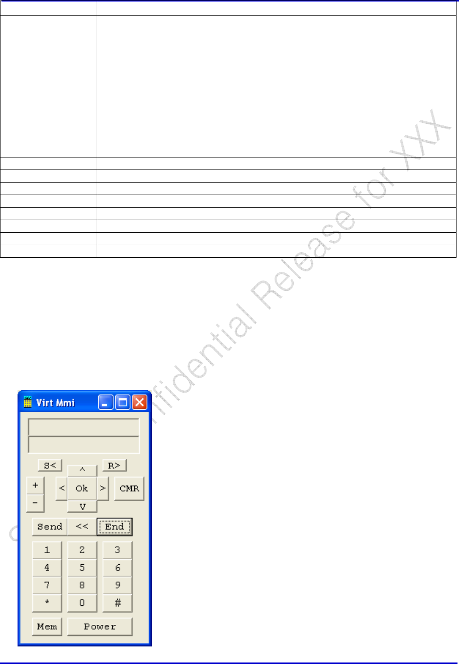
4 In-Call Mode
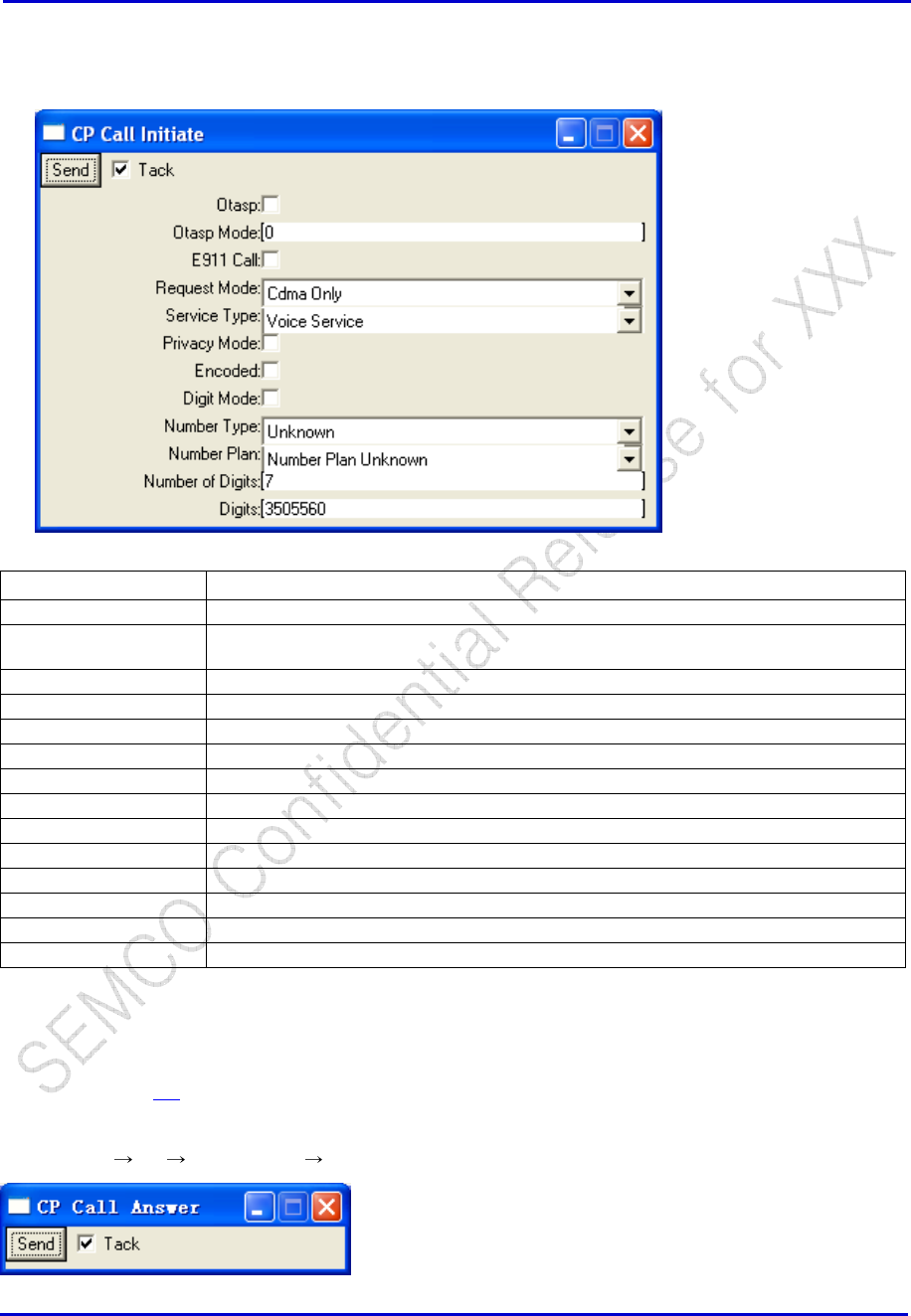
4.1 Voice Call Initiate
Utilities -> Virtual MMI Utility
To initiate a call, first click “Power” then dial any number and click “Send” Key on the Virt MMI.
Samsung Electro-Mechanics Co., Ltd. Proprietary
REV 0
Samsung Electro-Mechanics Co., Ltd.
Proprietary Page 17
As an alternative to using the Virtual MMI, calls can be initiated using:
CP → PS → UI Command → CP Call Initiate
Window Selections Definition
Send Send to perform call initiate command.
Tack If checked, the window will remain after clicking “Send”. If not checked, window will
close after clicking “Send”.
Otasp Check if it is an OTASP call.
Otasp Mode If it is an OTASP call, entry OTASP mode.
E911 Call Check if it is calling “E911”.
Request Mode
Service Option Choice a service option
Privacy Mode
Encoded
Digit Mode
Number Type
Number Plan
Number of Digits
Digits
4.2 Voice Call Answer
Similar to section 4.1, there are two ways of achieving this: through Virtual MMI or CP command.
1. Using Virtual MMI, click “Send” when “Call Alert” is displayed.
2. Or use CP PS UI Command CP Call Answer and click “Send”
Samsung Electro-Mechanics Co., Ltd. Proprietary
REV 0
Samsung Electro-Mechanics Co., Ltd.
Proprietary Page 18
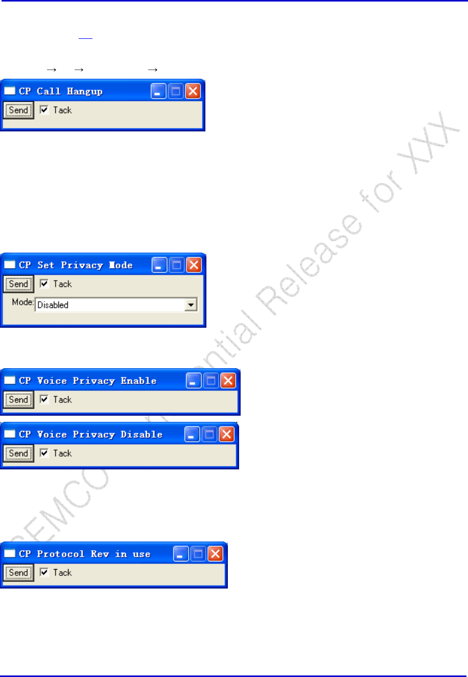
4.3 Voice Call Hang Up
Similar to section 4.1, there are two ways of achieving this: through Virtual MMI or CP command.
Using Virtual MMI, click “End” to terminate a call.
Or use CP PS UI Command CP Call Hangup and click “Send”
4.4 Voice Call Configuration
4.4.1 Voice Privacy Enable/Disable
CP → UI → CP Set Privacy Mode
CP → PS → Voice Privacy → CP Voice Privacy Enable (or Disable)
4.4.2 Protocol Rev in Use
CP → PS → CP Protocol Rev in use
This command returns the protocol revision in use for the mobile which responds as follows:
17:05:46.6< ETS, Id=CP Protocol Rev in use
17:05:46.7> ETS, Id=CP Protocol Rev in use, P_REV in use=IS_2000
Samsung Electro-Mechanics Co., Ltd. Proprietary
REV 0
Samsung Electro-Mechanics Co., Ltd.
Proprietary Page 19
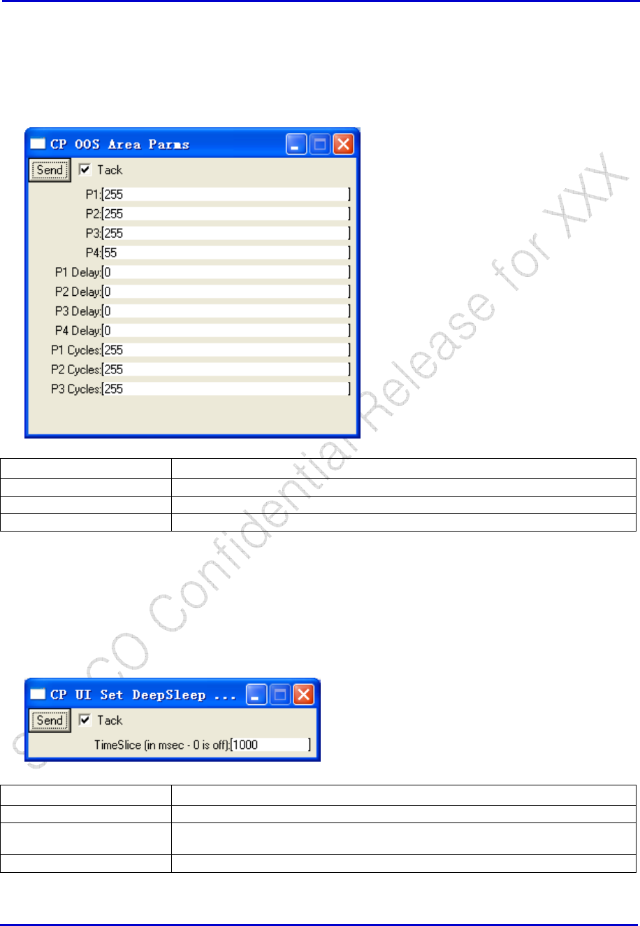
4.4.3 OOS Parameters
CP → PS → CP OOS Area Parms
Sending this command with the default values shown disables the phone from going out of service
(sleep) when the base station is not available for an extended period of time.
Window Selections Definition
P1-P4 # of attempts in phase 1-4
P1 Delay-P4 Delay sec delay between phase 1-4 attempts
P1 Cycles-P3 Cycles number of repeats of N attempts + a delay
4.4.4 Set Deep Sleep Slice Time
CP → UI → CP Set Deep Sleep Time Slice
Window Selections Definition
Send Send to perform the command.
Tack If checked, the window will remain after clicking “Send”. If not checked, window will
close after clicking “Send”.
Time Slice
Samsung Electro-Mechanics Co., Ltd. Proprietary
REV 0
Samsung Electro-Mechanics Co., Ltd.
Proprietary Page 20
4.5 Radio Control
4.5.1 Tx Pwr Detect Measurements Spy
Please refer to section 3.4 for detailed description.
4.5.2 RSSI for AMPS and CDMA
Please refer to section 3.1 for detailed description.
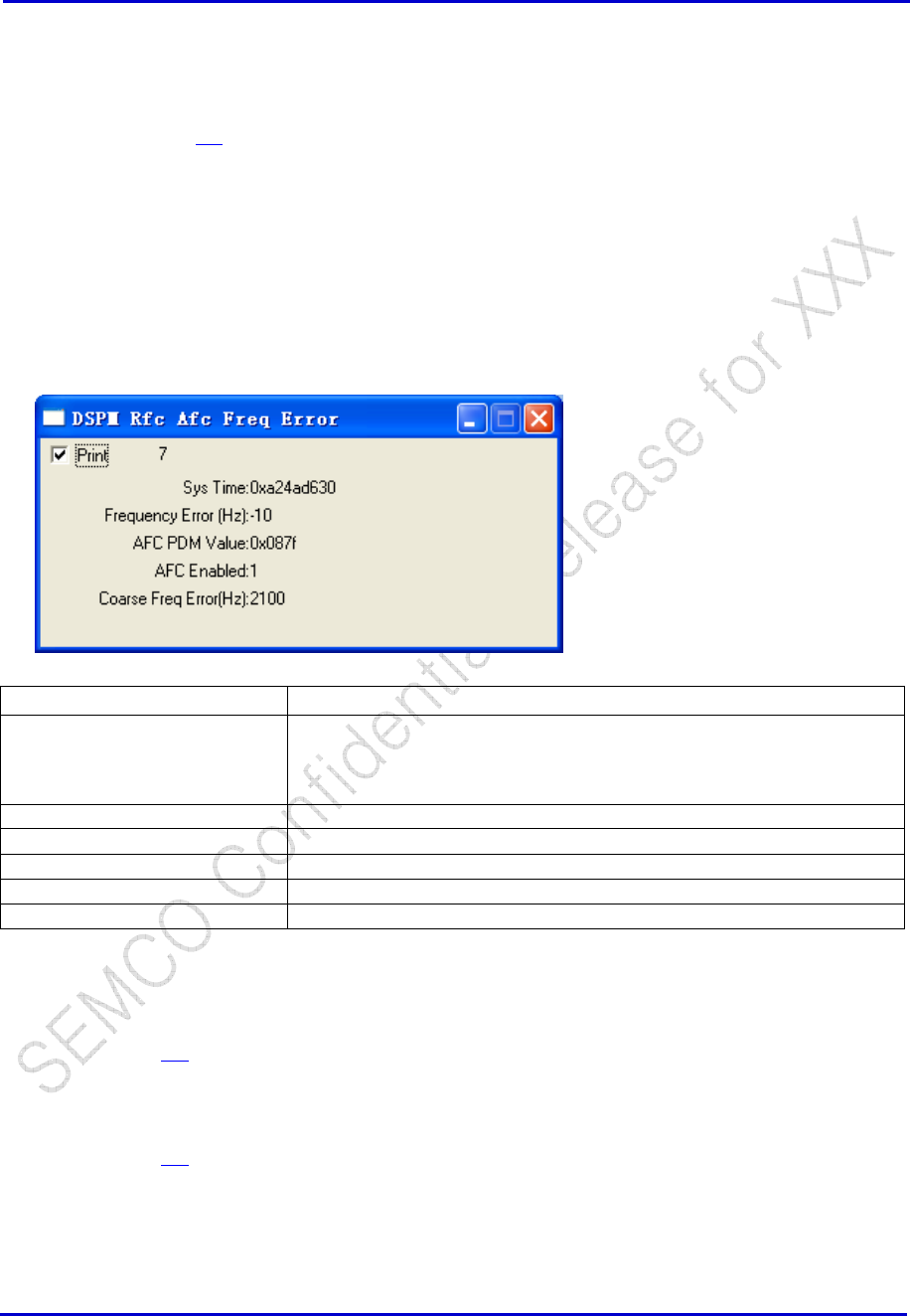
4.5.3 DSPM AFC Frequency Error Spy
DSPM → Spy → Rfc → DSPM Rfc Afc Freq Error
Window Selections Definition
Print If checked, the window will be printed onto the main log as a trace:
16:01:30.6> ETS, Id=DSPM Spy, SpyId=DSPM Rfc Afc Freq Error, Sys
Time=0xa24ad630, Frequency Error (Hz)=-10, AFC PDM Value=0x087f,
AFC Enabled=1, Coarse Freq Error(Hz)=2100
Sys Time Display system time for reference.
Frequency Error (Hz) Frequency error recorded.
AFC PDM Value AFC PDM Value used.
AFC Enabled AFC enabling state.
Coarse Freq Error (Hz) Display coarse frequency error.
4.5.4 HWD Freq Channel Trace
Please see section 3.5 for detailed descriptions.
4.5.5 Pilot Strength Spy
Please see section 3.6 for detailed descriptions.
Samsung Electro-Mechanics Co., Ltd. Proprietary
REV 0
Samsung Electro-Mechanics Co., Ltd.
Proprietary Page 21
5 Test/Debug Capability
5.1 Basics
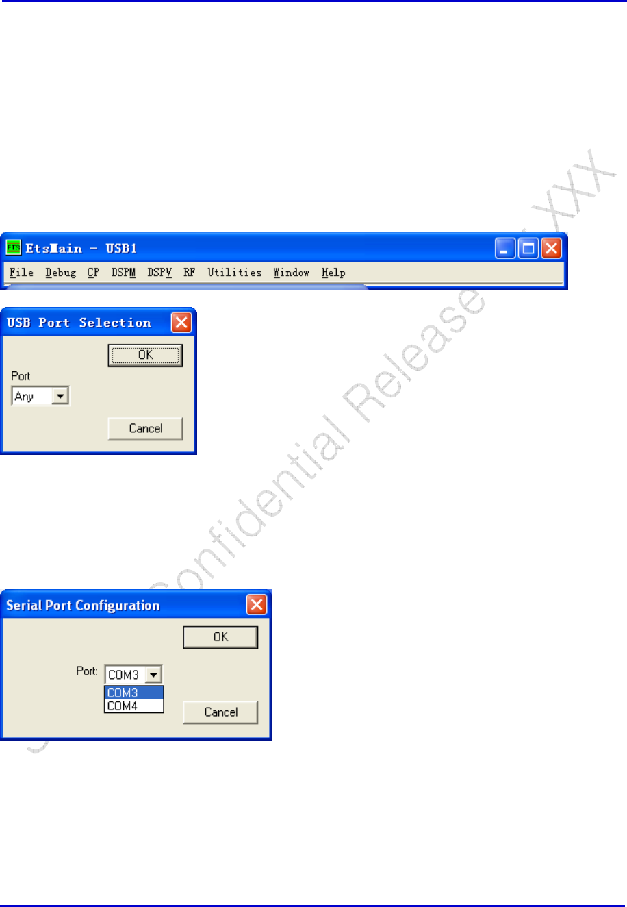
5.1.1 Communication Port Configuration
USB Port
Debug -> Comm -> USB
Then the ETS will show the connect port as USB
Serial Port
Debug → Comm → Serial, to select a COM port for communicate with DUT.
CP -> Options, set the Initial Baud Rate as 115200.
Samsung Electro-Mechanics Co., Ltd. Proprietary
REV 0
Samsung Electro-Mechanics Co., Ltd.
Proprietary Page 22
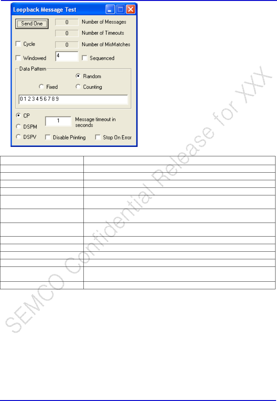
5.1.2 Loopback Test
Debug → Loopback
This function used to test the USB/COM communications with CP, DSPM, or DSPV.
Calls CP Loopback, DSPM Loopback, and DSPV Loopback.
Samsung Electro-Mechanics Co., Ltd. Proprietary
REV 0
Samsung Electro-Mechanics Co., Ltd.
Proprietary Page 23
Window Selections Definition
Number of Messages Number of messages sent.
Number of Timeouts Number of failures.
Number of Mismatches Number of differences between what was sent and what was received.
Send One Start Loopback test, one click will only sends out one command.
Cycle When checked, loopback test will continuously run until either Cycle is un-
checked or the Loopback window is closed. Will stop if you double clicked.
Windowed When checked, four loopback requests are sent before any reply is received.
Then sends and replies will alternate.
Fixed Pattern The user can supply a pattern of choice. Multiple words can be sent with a size
of: CP 0x00 – 0xff and 0x0000 – 0xffff for both DSPV and DSPM.
Stop On Error Test will stop on timeout or mismatch errors.
CP Tests the loopback with the CP.
DSPM Tests the loopback with the DSPM.
DSPV Tests the loopback with the DSPV.
Message timeout in seconds Length of time the system will wait for a reply before issuing the message,
“15:44:32.4: Timeout on message loopback”
Disable Printing When checked, messages to the Main Log window are suspended.
CP, DSPM, DSPV
Referring to Section 5.1.2 above, selecting CP, DSPM or DSPV for the loopback debug ensures
functionality of the specific sector in the mobile.
5.1.3 Raw Rx/Tx Serial Data
File → Raw → Tx or Rx
This command enables printing the raw data onto the Main Log window that describes the transfer of
serial data between ETS and the board.
Samsung Electro-Mechanics Co., Ltd. Proprietary
REV 0
Samsung Electro-Mechanics Co., Ltd.
Proprietary Page 24
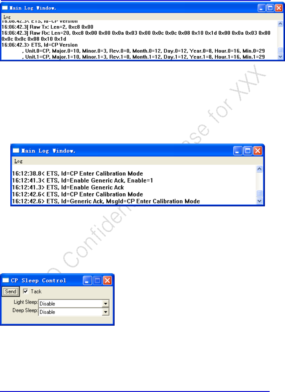
5.1.4 Enable Generic Ack
Debug → Enable Generic Ack
This command controls the display of the acknowledgement to any command sent from ETS to the
mobile. If enabled, a response message for each command is returned. A check mark displays next to the
command if enabled.
5.2 Test Modes
5.2.1 CP Sleep Control
CP → MON → CP Sleep Control
This command enables/disables the sleep operation of the CBP5.X software so the unit does/does not
power down for a sleep period and wakes up for only the wake-up period duration.
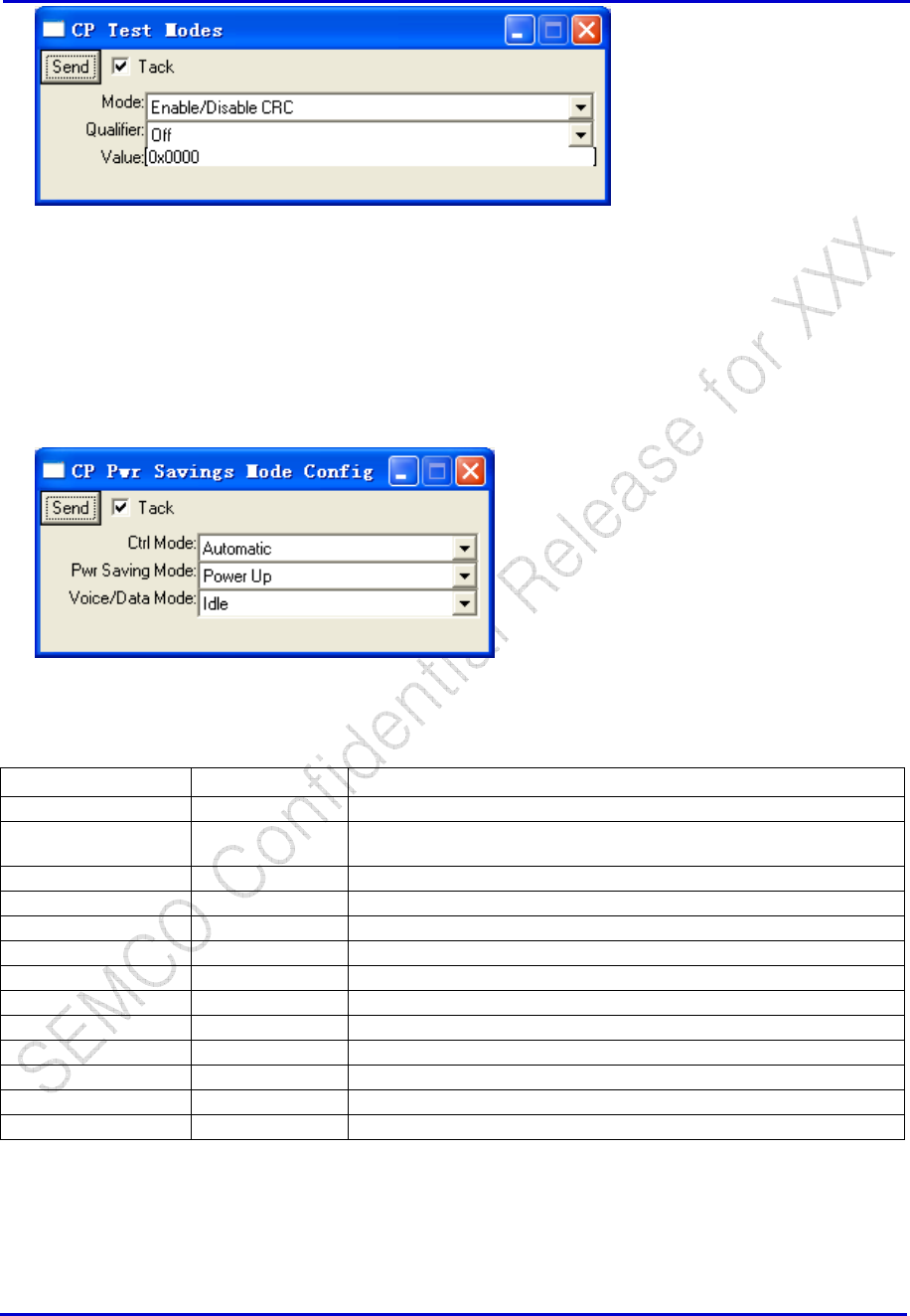
5.2.2 Slotted Mode Enable/Disable
CP → PS → Test mode → CP Test Modes
Samsung Electro-Mechanics Co., Ltd. Proprietary
REV 0
Samsung Electro-Mechanics Co., Ltd.
Proprietary Page 25
To disable slotted: Set Qualifier to “Off” and click “Send” (Value entry is ignored).
To enable slotted: Set Qualifier to “On” and click “Send” (Value entry is ignored).
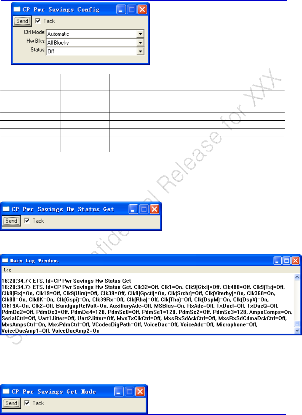
5.2.3 Pwr Savings Mode Config
CP → HWD → Pwr Savings → CP Power Savings Mode Config
sets the power savings mode
Window Selections
Options Definition
Send -- Send to perform power savings mode configuration.
Tack -- If checked, the window will remain after clicking “Send”. If not
checked, window will close after clicking “Send”.
Ctrl Mode Automatic Stack values are used – selections in Band and Channel are ignored.
Disable
Manual Values selected in Band and Channel are used
Pwr Saving Mode Power Up
Power Up Qpch
CDMA Rx Acq
CDMA Rx
Voice/Data Mode Idle
Mic On
Spkr On
Mic+Spkr On
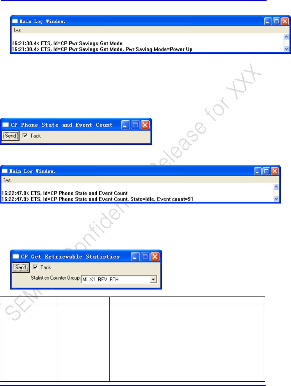
5.2.4 Pwr Savings Config
CP → HWD → Pwr Savings→ CP Pwr Savings Config
Samsung Electro-Mechanics Co., Ltd. Proprietary
REV 0
Samsung Electro-Mechanics Co., Ltd.
Proprietary Page 26
Window Selections
Options Definition
Send -- Send to perform power savings configuration.
Tack -- If checked, the window will remain after clicking “Send”. If not
checked, window will close after clicking “Send”.
Ctrl Mode Automatic Stack values are used – Hw Blks and Status are ignored.
Disable
Manual Selections made under “Hw Blks” and “Status” are used.
Hw Blks All Blocks This is the recommended setting for manual control.
Status On To turn blocks ON.
Off To turn blocks OFF.
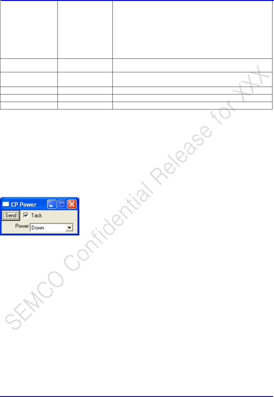
5.2.5 Pwr Savings Status Get
CP → HWD→ Pwr Savings → CP Pwr Savings HW Status Get
This command responds with the ON/OFF states of blocks within the chip. An example is shown below:
5.2.6 Pwr Savings Get Mode
CP → HWD → Pwr Savings→ CP Pwr Savings Get Mode
Samsung Electro-Mechanics Co., Ltd. Proprietary
REV 0
Samsung Electro-Mechanics Co., Ltd.
Proprietary Page 27
Below shows the command and respond while the mobile is in traffic:
5.2.7 Diagnostic Parameters (L1D, LMD)
5.2.8 Phone State And Event Control
CP → PS →CP Phone State and Event Count
Below shows an example when the mobile is on paging:
5.2.9 Get Retrievable Statistics
CP → PS →Retrievable Stat → CP Get Retrievable Statistics
Window Selections
Options Definition
Send Send to perform the command, with a response as follow:
16:24:10.6< ETS, Id=CP Get Retrievable Statistics, Statistics
Counter Group=MUX1_REV_FCH
16:24:10.6> ETS, Id=CP Get Retrievable Statistics
, Statistics Counter Group=MUX1_REV_FCH
, MUX1 REV FCH 1=0x000000a7
, MUX1 REV FCH 2=0x0000000a
, MUX1 REV FCH 3=0x00000000
, MUX1 REV FCH 4=0x00000014
, MUX1 REV FCH 5=0x00000024
, MUX1 REV FCH 6=0x00000049
Samsung Electro-Mechanics Co., Ltd. Proprietary
REV 0
Samsung Electro-Mechanics Co., Ltd.
Proprietary Page 28
, MUX1 REV FCH 7=0x00000000
, MUX1 REV FCH 8=0x0000047e
, MUX1 REV FCH 9=0x00000000
, MUX1 REV FCH 10=0x00000000
, MUX1 REV FCH 11=0x00000000
, MUX1 REV FCH 12=0x00000000
, MUX1 REV FCH 13=0x00000000
, MUX1 REV FCH 14=0x00000000
Tack If checked, the window will remain after clicking “Send”. If not
checked, window will close after clicking “Send”.
Statistics Counter
Group
MUX1_REV_FCH
MUX1_FOR_FCH
PAG
ACC
5.2.10 Timer Enable
5.2.11 PS Enable/Disable
CP Power:
CP → PS → UI Command → CP Power
This command enables/disables the protocol stack but does not perform any resets to the system. It
serves the same purpose as the “Power” button on the MMI, which in turn performs a soft reset to the
system.
5.2.12 OOS Parameter
Please refer to section 4.4.3.
Samsung Electro-Mechanics Co., Ltd. Proprietary
REV 0
Samsung Electro-Mechanics Co., Ltd.
Proprietary Page 29
5.2.13 Service Option - SO (TBD)
5.3 RF Interface and Control
5.3.1 CDMA Configuration
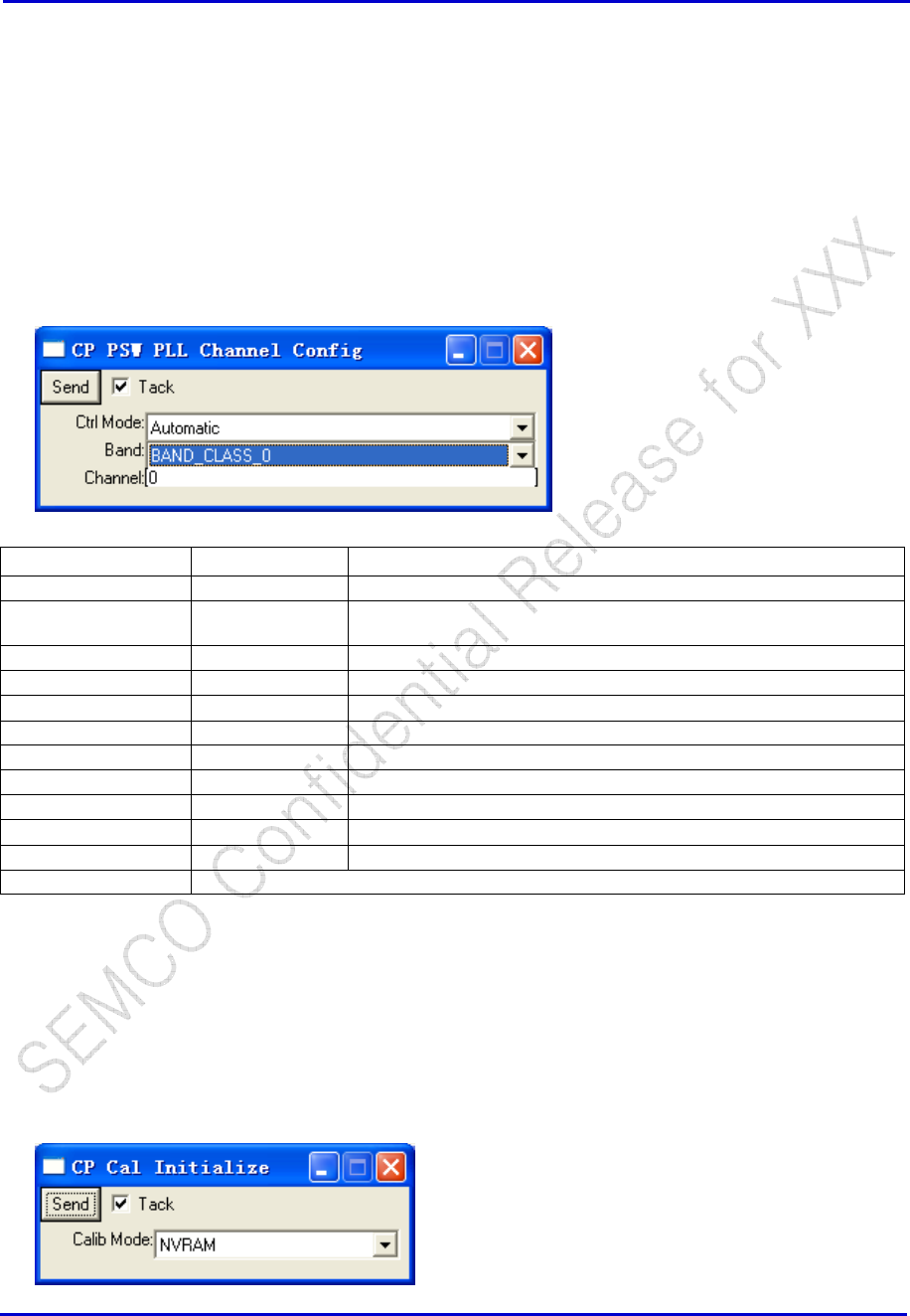
CP PLL Channel Config
RF → CP PSW PLL Channel Config
Window Selections
Options Definition
Send -- Send to perform the PLL channel configuration.
Tack -- If checked, the window will remain after clicking “Send”. If not
checked, window will close after clicking “Send”.
Ctrl Mode Automatic Stack values are used – selections in Band and Channel are ignored.
Disable
Manual Values selected in Band and Channel are used
Band PCS Selects BAND_CLASS_1
AMPS (NONE)
Cellular Selects BAND_CLASS_0
JTACS Selects BAND_CLASS_3 (Japanese Cellular)
Korean KPCS Selects BAND_CLASS_4 (Korean PCS)
450M NMT Selects BAND_CLASS_5
Channel User defined channel number
CP PLL Register Config
CP Cal initialize
RF → CP Cal Initialize
Samsung Electro-Mechanics Co., Ltd. Proprietary
REV 0
Samsung Electro-Mechanics Co., Ltd.
Proprietary Page 30
Window Selections Options Definition
Send -- Send to perform the Cal Initialize command.
Tack -- If checked, the window will remain after clicking “Send”. If
not checked, window will close after clicking “Send”.
Calib Mode NVRAM This loads DBM cache of the DB templates onto the SRAM
cache for execution.
Default This loads a default cal file onto flash. Command “CP CAL
Init NVRAM” (under RF) is needed in conjunction after the
Cal Initialize command.
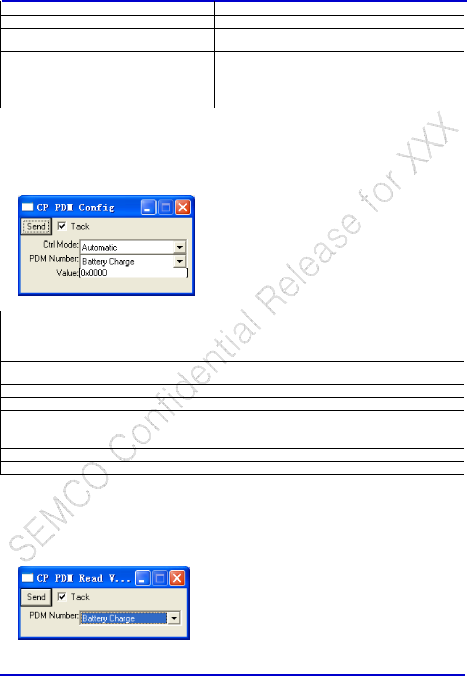
CP PDM Config
RF → CP PDM Config
Window Selections Options Definition
Send -- Send to perform PDM Configuration Control.
Tack -- If checked, the window will remain after clicking “Send”. If not
checked, window will close after clicking “Send”.
Ctrl Mode Automatic Stack values are used – selections in PDM Number and Value
are ignored.
Manual Values selected in Band and Channel are used
Disable
PDM Number Battery Charge Battery Charge PDM value set
Afc Automatic Frequency Control PDM value set
Tx Agc TX AGC PDM value set
Rx Agc RX ACG PDM Value set
Value Hex value in the format of 0x0000
CP PDM Read value
RF → CP PDM Read Value
Samsung Electro-Mechanics Co., Ltd. Proprietary
REV 0
Samsung Electro-Mechanics Co., Ltd.
Proprietary Page 31
Window Selections Options Definition
Send -- Send to perform specified PDM Read.
Tack -- If checked, the window will remain after clicking “Send”.
If not checked, window will close after clicking “Send”.
PDM Number Battery Charge Battery Charge PDM value set
Afc Automatic Frequency Control PDM value set
Tx Agc TX AGC PDM value set
Rx Agc RX ACG PDM Value set
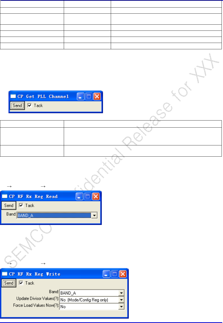
CP Get PLL Channel
RF → CP Get PLL Channel
Window Selections Definition
Send Send to perform the command of getting PLL channel, response as shown:
16:35:21.8< ETS, Id=CP Get PLL Channel
16:35:21.8> ETS, Id=CP Get PLL Channel, Band=BAND_A, Channel=0x00c9
Tack If checked, the window will remain after clicking “Send”. If not checked, window
will close after clicking “Send”.
Note, the returned value is in Hex mode.
CP RF Rx Reg Read (TBD)
RF RF Registers CP RF Rx Reg Read
This message will select the relevant RF registers based on the Radio Design selected by the “RF Target
Option” in Section 2.6
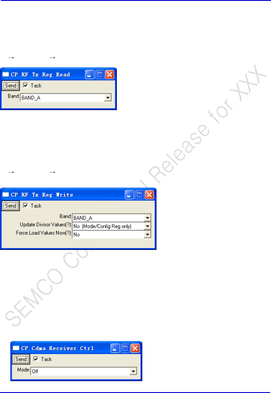
CP RF Rx Reg Write (TBD)
RF RF Registers CP RF Rx Reg Write
Samsung Electro-Mechanics Co., Ltd. Proprietary
REV 0
Samsung Electro-Mechanics Co., Ltd.
Proprietary Page 32
This message will select the relevant RF registers based on the Radio Design selected by the “RF Target
Option” in Section 2.6
CP RF Tx Reg Read (TBD)
RF RF Registers CP RF Tx Reg Read
This message will select the relevant RF registers based on the Radio Design selected by the “RF Target
Option” in Section 2.6
CP RF Tx Reg Write (TBD)
RF RF Registers CP RF Tx Reg Write
This message will select the relevant RF registers based on the Radio Design selected by the “RF Target
Option” in Section 2.6
5.3.2 CDMA Receiver
CP CDMA Receiver Control
RF → CDMA → CP CDMA Receiver Ctrl
Samsung Electro-Mechanics Co., Ltd. Proprietary
REV 0
Samsung Electro-Mechanics Co., Ltd.
Proprietary Page 33
Window Selections Options Definition
Send Send to perform CDMA Receiver Control command.
Tack If checked, the window will remain after clicking “Send”.
If not checked, window will close after clicking “Send”.
Mode Off Turn CDMA Receiver OFF.
On Turn CDMA Receiver ON.
CDMA PLL Channel Config
Freq Error Trace
RSSI Trace
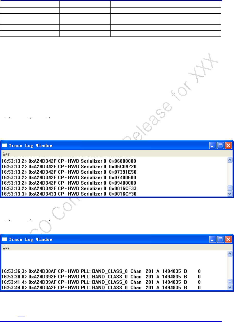
HWD CP Serializer Trace
CP TRACE HWD CP Serializer
This trace is useful for monitoring all the activity on the serializer bus, particularly for control of the RF
chips
HWD Freq Channel Trace
CP TRACE HWD CP Freq Channel
This trace shows the channels which the CP cycles through while trying to acquire a Base Station.
L1D Search Results Active
Refer to 3.6
Samsung Electro-Mechanics Co., Ltd. Proprietary
REV 0
Samsung Electro-Mechanics Co., Ltd.
Proprietary Page 34
Rx AGC Parameters (L1D)
Clear FER
5.3.3 CDMA Transmitter
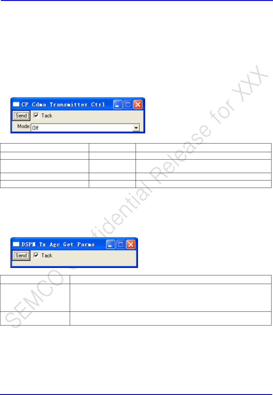
CP CDMA Transmitter Control
RF → CDMA → CP CDMA Transmitter Ctrl
Window Selections Options Definition
Send Send to perform Transmitter control command.
Tack If checked, the window will remain after clicking “Send”.
If not checked, window will close after clicking “Send”.
Mode On Turn CDMA transmitter ON.
Off Turn CDMA transmitter OFF.
DSPM Tx AGC Get Params
RF → CDMA → DSPM Tx AGC Get Parms
Window Selections Definition
Send Send to get the HW Value of the Tx AGC currently operating at, response as shown:
16:55:08.8< ETS, Id=DSPM Tx Agc Get Parms
16:55:08.8> ETS, Id=DSPM Tx Agc Get Parms, Power=0.000000, HW
Value=0x0994
Tack If checked, the window will remain after clicking “Send”. If not checked, window will
close after clicking “Send”.
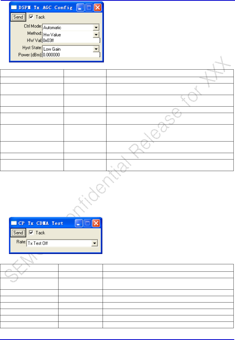
DSPM Tx AGC Config
RF → CDMA → DSPM Tx AGC Config
Samsung Electro-Mechanics Co., Ltd. Proprietary
REV 0
Samsung Electro-Mechanics Co., Ltd.
Proprietary Page 35
Window Selections Options Definition
Send Send to perform Tx AGC control command.
Tack If checked, the window will remain after clicking “Send”. If not
checked, window will close after clicking “Send”.
Ctrl Mode Automatic Stack values are used – selections in preceding entries are
ignored.
Manual Values entered in the preceding entries are used.
Method HW Value Set to use PDM value from the Tx AGC Cal table. Selecting
this ignores the field “Power(dBm)”.
dB Gain Set to use “power” column from the Tx AGC Cal table for
reference to transmit. Selecting this ignores the field “HW
Val”.
HW Val PDM value in Hex referenced from CP DB HWD Tx AGC
table.
Hyst State Low/Mid/High Gain state for the transmitter.
Power(dBm) Actual transmitted power in dBm referenced from CP DB
HWD Tx AGC table.
CP CDMA Tx Test
RF → CDMA → CP Tx CDMA Test
Window Selections Options Definition
Send Send to enable TX CDMA test in specified Tx rate.
Tack If checked, the window will remain after clicking “Send”. If not
checked, window will close after clicking “Send”.
Rate Tx Test Off Turn Tx OFF.
Access Turn TX ON to full rate but transmit through Access channel.
Tr Full Rate Turn Tx ON to full rate. This is used for debug purposes most.
Tr ½ Rate Turn Tx ON to half rate.
Tr ¼ Rate Turn Tx ON to quarter rate.
Tr 1/8 Rate Turn Tx ON to eighth rate.
Samsung Electro-Mechanics Co., Ltd. Proprietary
REV 0
Samsung Electro-Mechanics Co., Ltd.
Proprietary Page 36
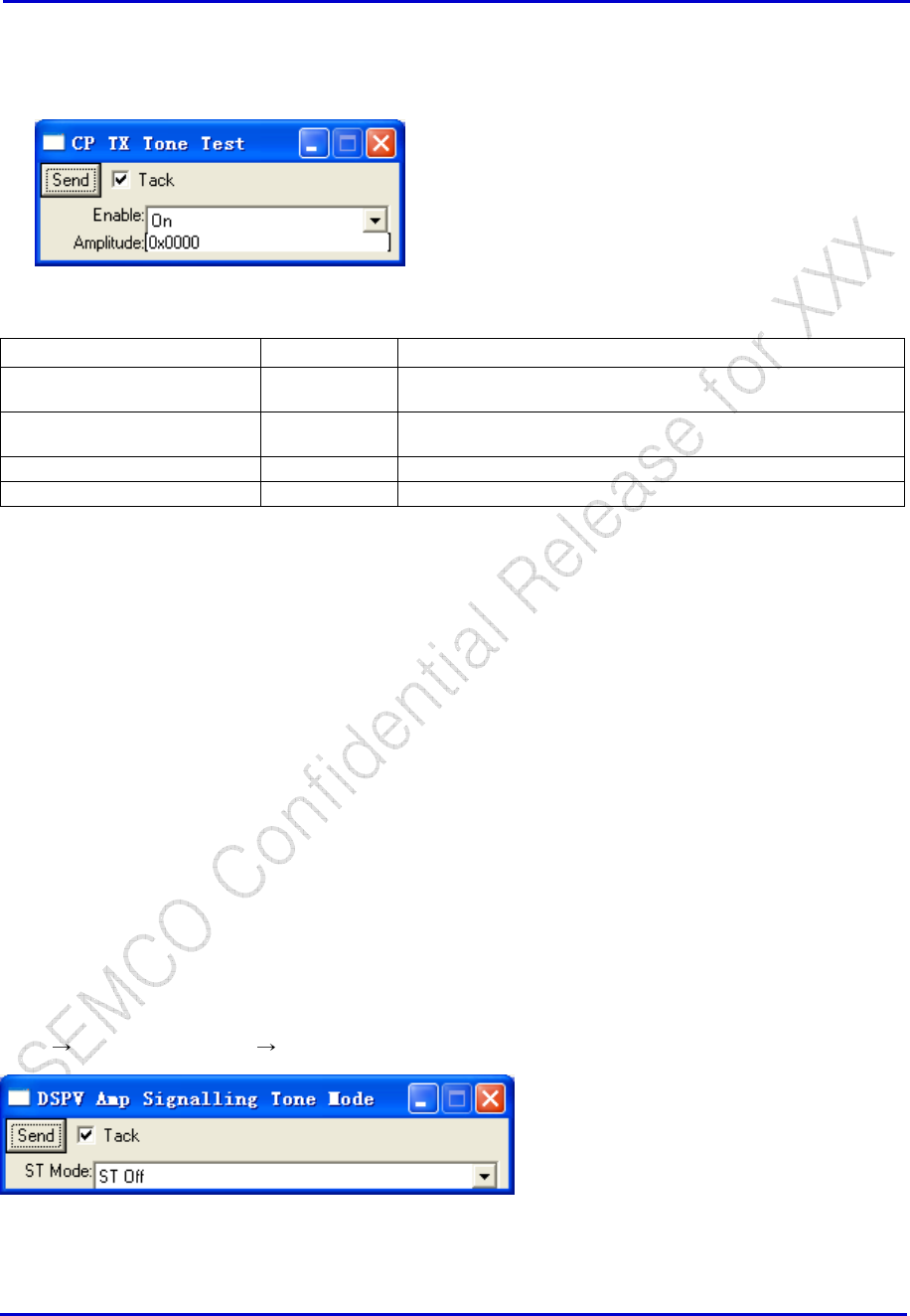
Tx Tone Test
RF → CP TX Tone Test
Window Selections Options Definition
Send -- Send to transmit a single tone from the transmitter instead of a
CDMA spectrum.
Tack -- If checked, the window will remain after clicking “Send”. If not
checked, window will close after clicking “Send”.
Enable On/Off Turn TX tone ON or OFF.
Amplitude -- Amplitude of tone desired, typical value: 0x0200, in Hex.
HWD CP Serializer Trace
HWD Freq Channel Trace
Tx AGC Parameters (L1D)
CP Tune Radio
Get RSSI
Rx Calibration
Signaling Tone Mode (TBD)
DSPV DSPV Amp Rev Path DSPV Amp Signalling Tone Mode
Samsung Electro-Mechanics Co., Ltd. Proprietary
REV 0
Samsung Electro-Mechanics Co., Ltd.
Proprietary Page 37
Set Busy Idle Status
Tx Fixed Freq
Tx Calibration
5.3.4 AFC
DSPM AFC Get Params
DSPM AFC Config
AFC Cal Parameters (L1D)
5.3.5 RF Pin Control
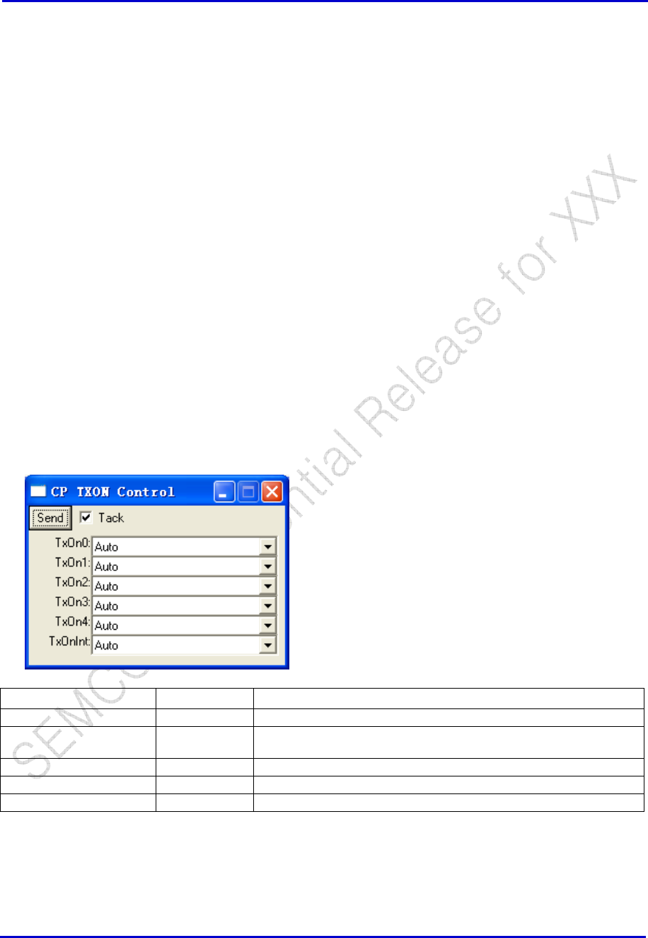
CP TXON Control
RF → CP TXON Control
Window Selections Options Definition
Send -- Send to enable TXON Control
Tack -- If checked, the window will remain after clicking “Send”. If not
checked, window will close after clicking “Send”.
TxOn [0:4] Off Turn TxOn OFF.
On Turn TxOn ON.
Auto Allow CBP software to control the TxOn
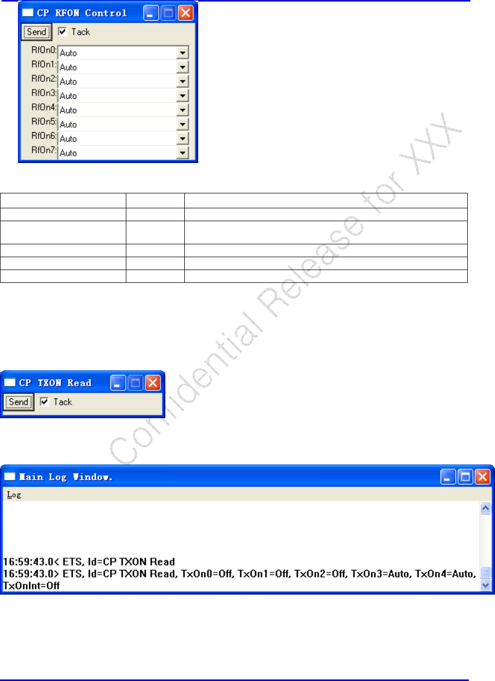
CP RXON Control
RF → CP RXON Control
Samsung Electro-Mechanics Co., Ltd. Proprietary
REV 0
Samsung Electro-Mechanics Co., Ltd.
Proprietary Page 38
Window Selections Options Definition
Send Send to enable RFON Control
Tack If checked, the window will remain after clicking “Send”. If not
checked, window will close after clicking “Send”.
RfOn [0:7] Off Turn RfOn OFF.
On Turn RfOn ON.
Auto Allow CBP software to control the RfOn
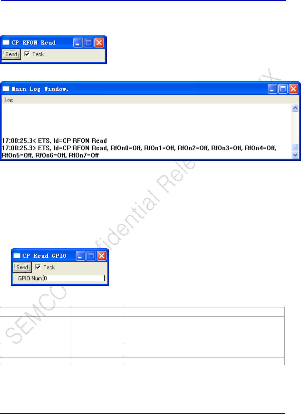
CP TXON Read
RF → CP TXON Read
Samsung Electro-Mechanics Co., Ltd. Proprietary
REV 0
Samsung Electro-Mechanics Co., Ltd.
Proprietary Page 39
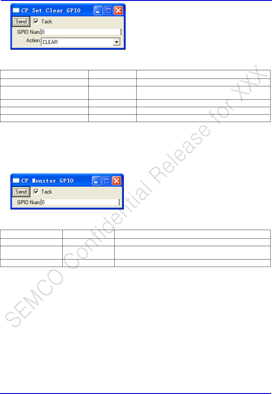
CP RXON Read
RF → CP RXON Read
5.3.6 GPIO Control
GPIO Read / GPIO Write
CP → MON → GPIO → CP Read GPIO
Window Selections Options Definition
Send -- Send to read the relevant GPIO. Caution: This command will
set the GPIO to INPUT mode and perform the read. The
original state is not preserved so this command should only be
performed on GPIOs which are known to be Inputs.
Tack -- If checked, the window will remain after clicking “Send”. If not
checked, window will close after clicking “Send”.
GPIO Num [0:47] Read the Relevant GPIO
CP → MON → GPIO → CP Set Clear GPIO
Samsung Electro-Mechanics Co., Ltd. Proprietary
REV 0
Samsung Electro-Mechanics Co., Ltd.
Proprietary Page 40
Window Selections Options Definition
Send Send to read the relevant GPIO
Tack If checked, the window will remain after clicking “Send”.
If not checked, window will close after clicking “Send”.
GPIO Num [0:47] Read the Relevant GPIO
Action SET Sets the GPIO to “0”
CLEAR Clears the GPIO to “1”
GPIO Read Monitor
CP → MON →GPIO → CP Monitor GPIO
Window Selections Options Definition
Send -- Send to Monitor the relevant GPIO
Tack -- If checked, the window will remain after clicking “Send”. If not
checked, window will close after clicking “Send”.
GPIO Num [0:47]
GPIO (trace ???)
5.3.7 Serializer
This section should be read in conjunction with the Serial Programmer chapters in References [2][3].
Serializer Configuration
CP → HWD → CP Serializer Config
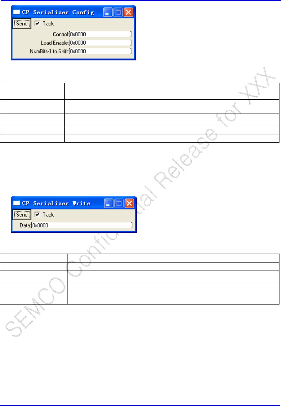
Samsung Electro-Mechanics Co., Ltd. Proprietary
REV 0
Samsung Electro-Mechanics Co., Ltd.
Proprietary Page 41
Window Selections Definition
Send Send to set the Serializer Configuration
Tack If checked, the window will remain after clicking “Send”. If not checked, window will
close after clicking “Send”.
Control Programs the register SER0_CTRL (listed as SER#_CTRL in Reference [3]). The PTR
field can only be set to “000”.
Load Enable Programs the register SER0_LE (listed as SER#_LE in Reference [3])
NumBits-1 to Shift Programs the register SER0_BC (listed as SER#_BC in Reference [3])
Serializer Write
CP → HWD → CP Serializer Write
Window Selections Definition
Send Send to set the Serializer Configuration
Tack If checked, the window will remain after clicking “Send”. If not checked, window will
close after clicking “Send”.
Data Write Data to Serializer, which has been configured (see Section 0). This data is
loaded into the registers SER0_D1, SER0_D0 (listed as SER#_D1, SER#_D0 in
Reference [3])
5.4 SMS
Here, we only provide a brief summary to allow the user the user to access the SMS menu. The details of
the SMS messages are covered in great detail in [6], while background information on SMS is provided in
[5].

Samsung Electro-Mechanics Co., Ltd. Proprietary
REV 0
Samsung Electro-Mechanics Co., Ltd.
Proprietary Page 42
5.4.1 Connect (CP PS SMS CP SMS Connect)
5.4.2 Disconnect (CP PS SMS CP SMS Disconnect)
5.4.3 Broadcast Connect (CP PS SMS CP SMS Bcast Connect)
5.4.4 Broadcast Disconnect (CP PS SMS CP SMS Bcast Disconnect)
5.4.5 User Ack (CP PS SMS CP SMS User Ack)
5.4.6 Service Option Pref (CP PS SMS CP SMS Srv Opt Pref)
5.4.7 Cancel (CP PS SMS CP SMS Cancel)
5.4.8 Broadcast Parameters (CP PS SMS CP SMS Bcast Parms)
5.4.9 Term Status (CP PS SMS CP SMS Term Status)
5.4.10 Cause Code Status (CP PS SMS CP SMS Cause Code Status)
5.5 Database Upload/Download
5.5.1 Flash Device
Flash Download for Reference Phones
1. Phone has been connected to the ETS.
2. Before you begin to download cp.rom, set Flash Download Timeout to 200. Open File-
>Options and then set Flash Download Timeout to 200, then click OK button, see the following
dialog box.
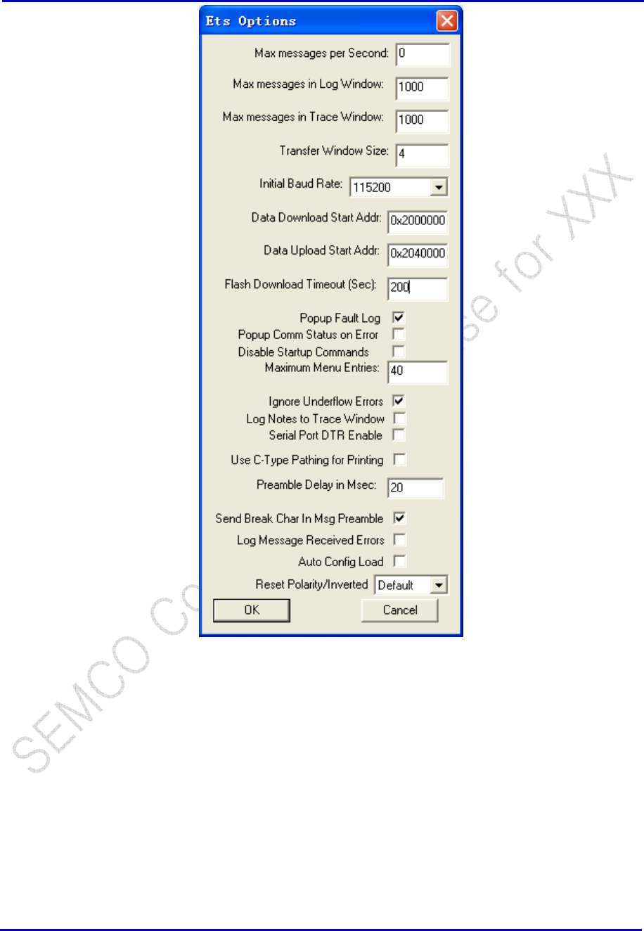
Samsung Electro-Mechanics Co., Ltd. Proprietary
REV 0
Samsung Electro-Mechanics Co., Ltd.
Proprietary Page 43
3. Open File->Flash Download, you can see the flash memory download dialog, see the following
bitmap. Select the drop down box CP Boot for Flash Section; click the Browse to set your new
boot.rom path, set “wait for boot load command” check box on, then the “Download”
button will be disabled.
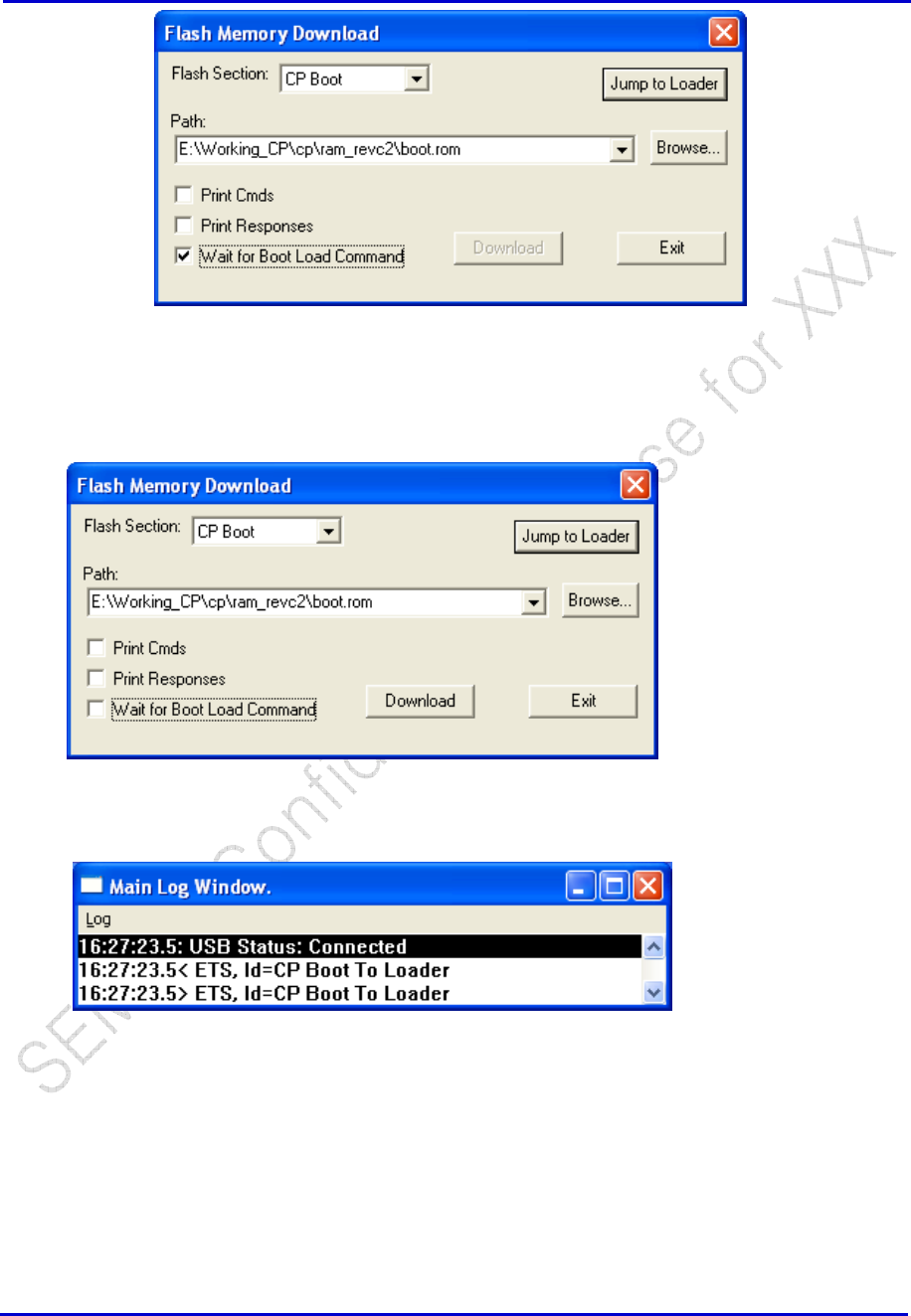
Samsung Electro-Mechanics Co., Ltd. Proprietary
REV 0
Samsung Electro-Mechanics Co., Ltd.
Proprietary Page 44
4. Power OFF the phone, connect the phone with PC and Power ON the phone, “Wait for boot
load command” check box becomes unchecked, and “Download” button is enabled.
You will see “CP Boot Loader” in the ETS Log Window.
5. Click “Download” button to begin download boot.rom, you can see the CP Flash Download
dialog. ETS erases the flash, and then begin to write boot.rom in flash, and you can see the
download progress.
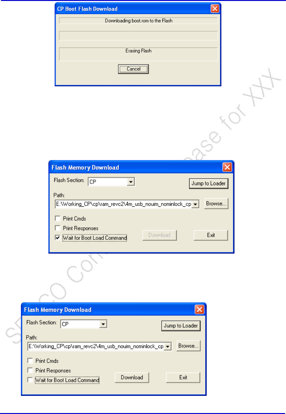
Samsung Electro-Mechanics Co., Ltd. Proprietary
REV 0
Samsung Electro-Mechanics Co., Ltd.
Proprietary Page 45
6. Open File->Flash Download, you can see the flash memory download dialog, see the following
bitmap. Select the drop down box CP for Flash Section; click the Browse to set your new
cp.rom path, set “wait for boot load command” check box on, then the “Download” button
will be disabled.
7. Power OFF the phone, then Power ON the phone again, “Wait for boot load command” check
box becomes unchecked, and “Download” button is enabled.
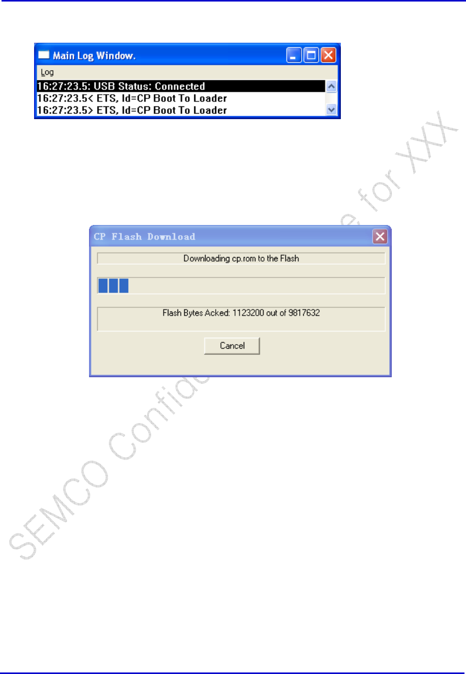
Samsung Electro-Mechanics Co., Ltd. Proprietary
REV 0
Samsung Electro-Mechanics Co., Ltd.
Proprietary Page 46
You will see “CP Boot Loader” in the ETS Log Window.
8. Click “Download” button to begin download cp.rom, you can see the CP Flash Download dialog.
ETS erases the flash, and then begin to write cp.rom in flash, and you can see the download
progress.
9. After download finished, power off the phone (If there is a battery in your phone, please
remove and re-insert), then power on the phone.
Flash Download FOR CDS Products (NOT FOR Reference Phones)
File → Flash Download
Use to download CP Boot, CP, DSPM, and DSPV code to flash memory. System must be in boot mode to
download any section of flash. See Reference [8] for more details.
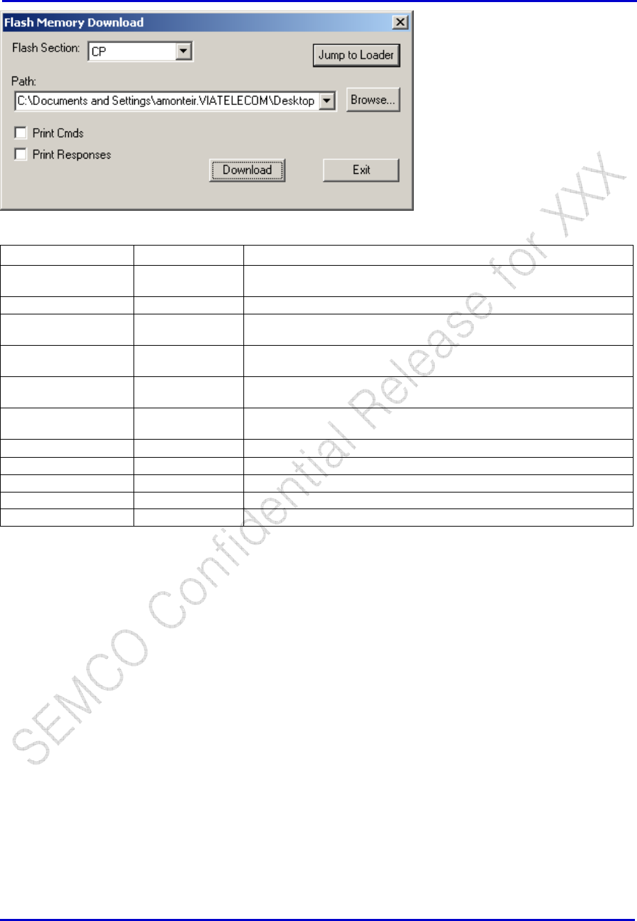
Samsung Electro-Mechanics Co., Ltd. Proprietary
REV 0
Samsung Electro-Mechanics Co., Ltd.
Proprietary Page 47
Window Selections
Options Definition
Flash Section: CP Boot Downloads CP Boot code to flash memory when Download is
clicked.
CP Downloads CP code to flash memory when Download is clicked.
DSPM Downloads DSPM code or DSPM patches to flash memory when
Download is clicked.
DSPV Downloads DSPV code or DSPV patches to flash memory when
Download is clicked.
ALL FLASH Downloads FLASH Image to flash memory when Download is
clicked.
FSM_DATA/FSM
_USER
Downloads File system to flash memory when Download is clicked.
Path Select recent paths or Browse mounted disks
Print Cmds Used to print the commands sent from ETS to the Flash.
Print Response Used to print the responses sent from Flash to ETS.
Download Execute download of selected file
Exit Close window
Flash Program
CP → Flash → CP Flash Program
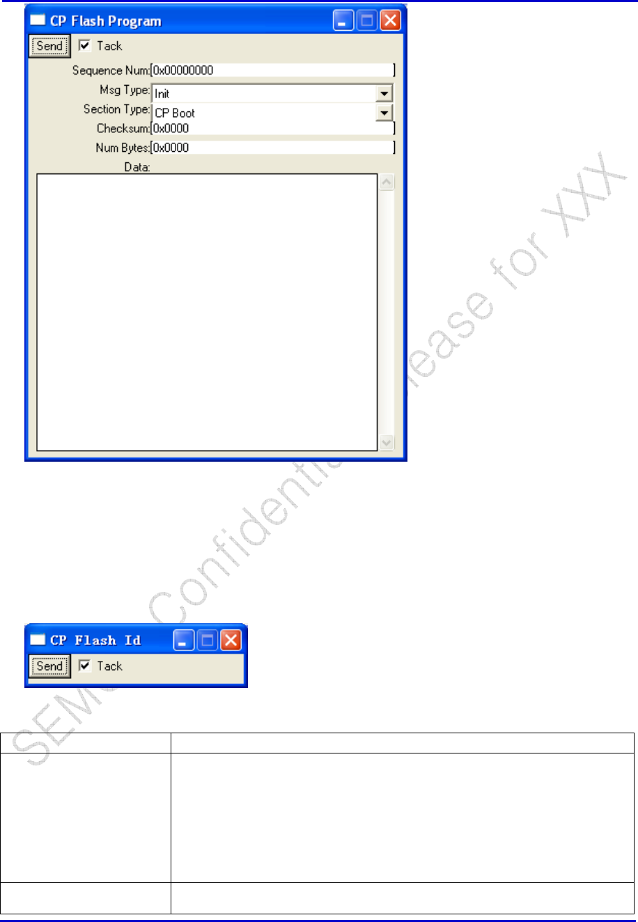
Samsung Electro-Mechanics Co., Ltd. Proprietary
REV 0
Samsung Electro-Mechanics Co., Ltd.
Proprietary Page 48
Flash ID
CP → Flash → CP Flash ID
Used to display the type and manufacture of the Flash device in usi. The customer must update
hwdflash.c
if any other than the AMD AM29DL163CB flash is used.
Window Selections Definition
Send Data that is displayed in the Main Log window when Send is clicked in the above
example.
10:17:40.1< ETS, Id=CP Flash Id
10:17:40.1> ETS, Id=CP Flash Id, Manf Id=0x0001, Dev Id=0x002b
In this example, the flash used is an AM29DL163CB manufactured by AMD. See
hwdflash.c for more details.
Tack When checked, window will remain on screen after every Send. When not
checked, window will close after a Send
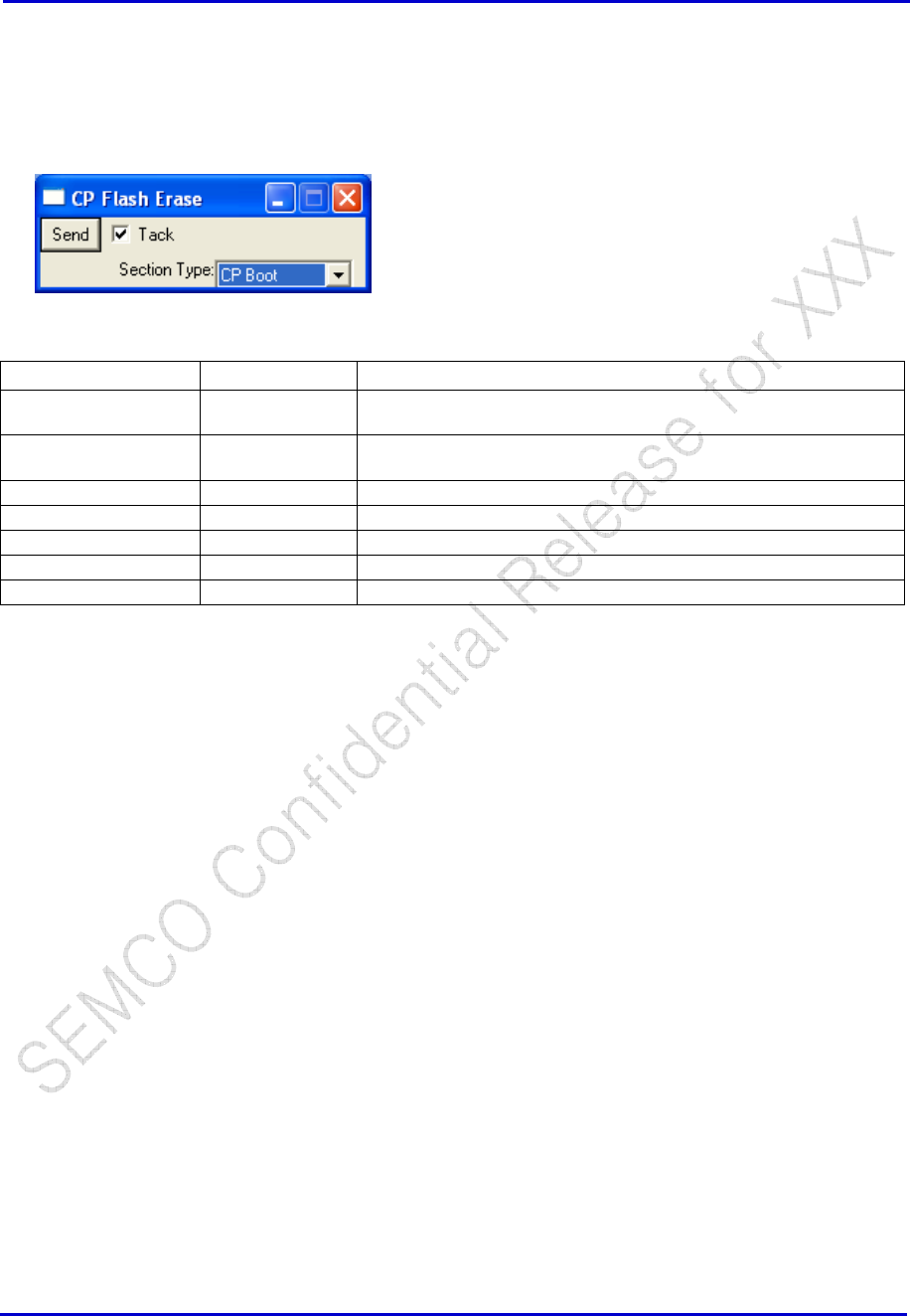
Samsung Electro-Mechanics Co., Ltd. Proprietary
REV 0
Samsung Electro-Mechanics Co., Ltd.
Proprietary Page 49
Flash Erase
CP → Flash → CP Flash Erase
Window Selections Options Definition
Send Data that is displayed in the Main Log window when Send is clicked
in the above example.
Tack When checked, window will remain on screen after every Send.
When not checked, window will close after a Send
Section Type CP Boot Selects the CP Boot section of Flash.
CP Selects the CP section of Flash.
DSPM Selects the DSPM section of Flash.
DSPV Selects the DSPV section of Flash
All Selects all sections of Flash.
Configure Timers
IQ Polarity
Tx Voice Mode
Random Distribution
Rx Word Sync
Rx RSSI
AFC
Tx Levels

Samsung Electro-Mechanics Co., Ltd. Proprietary
REV 0
Samsung Electro-Mechanics Co., Ltd.
Proprietary Page 50
5.5.2 RF Calibration Data
Hwd AFC Data
CP→DB→DB Templates→Common→CP DB HWD AFC Data
Hwd Battery Data
CP
→
DB
→
DB Templates
→
Common
→
CP DB HWD Battery Data.
Hwd Temperature Data
CP→DB→DB Templates→Common→CP DB HWD Temperature Data
Hwd Aux ADC Data
Hwd PDM Data
CP→DB→DB Templates→Common→CP DB HWD PDM Voltage Data
Hwd Bandgap Trim Data
CP→DB→DB Templates→Common→CP DB HWD BandGap Trim Data
Hwd Misc Cal Data ?
PCS Tx AGC
CP→DB→DB Templates→ BAND B →CP DB HWD BAND B Tx AGC
PCS Tx AGC Freq Chan Adj
CP→DB→DB Templates→ BAND B →CP DB HWD BAND B Tx AGC Freq Chan Adj
PCS Tx AGC Temp Adj
CP→DB→DB Templates→ BAND B →CP DB HWD BAND B Tx AGC Temp Adj
PCS Tx AGC Battery Voltage Adj
CP→DB→DB Templates→ BAND B →CP DB HWD BAND B Tx AGC Batt Volt Adj.
PCS Tx AGC Limit Freq Chan Adj
CP→DB→DB Templates→ BAND B →CP DB HWD BAND B Tx Limit Freq Chan Adj

Samsung Electro-Mechanics Co., Ltd. Proprietary
REV 0
Samsung Electro-Mechanics Co., Ltd.
Proprietary Page 51
PCS TxAGC Limit Temperature Adjustment
CP→DB→DB Templates→ BAND B →CP DB HWD BAND B Tx Limit Temp Adj.
PCS TxAGC Closed Loop RF Power Measurement
CP→DB→DB Templates→ BAND B →CP DB HWD BAND B Tx Pwr Detect
PCS TxAGC Closed Loop Frequency Channel Adjustment
CP→DB→DB Templates→ BAND B →CP DB HWD BAND B Tx AGC Pwr Det Freq Chan Adj.
PCS TxAGC Closed Loop Battery Voltage Adjustment
CP→DB→DB Templates→ BAND B → CP DB HWD BAND B Tx Pwr Det Max Pwr Batt Voltage Adj.
PCS TxAGC Closed Loop Temperature Adjustment
CP→DB→DB Templates→ BAND B →CP DB HWD BAND B Tx AGC Pwr Det Temp Adj.
PCS Rx AGC
CP->DB->DB Templates-> BAND B ->CP DB HWD BAND B RxAGC CP DB HWD PCS RxAGC
PCS Rx AGC Freq Chan Adj
CP→DB→DB Templates→ BAND B →CP DB HWD BAND B Rx AGC Freq Chan Adj
PCS Rx AGC Temp Adj
CP→DB→DB Templates→ BAND B →CP DB HWD BAND B Rx AGC Temp Adj
CELL Tx AGC
CP→DB→DB Templates→ BAND A →CP DB HWD BAND A Tx AGC
CELL Tx AGC Freq Chan Adj
CP→DB→DB Templates→ BAND A →CP DB HWD BAND A Tx AGC Freq Chan Adj
CELL Tx AGC Temp Adj
CP→DB→DB Templates→ BAND A →CP DB HWD BAND A Tx AGC Temp Adj
CELL Tx AGC Battery Voltage Adj
CP→DB→DB Templates→ BAND A →CP DB HWD BAND A Tx AGC Batt Volt Adj.

Samsung Electro-Mechanics Co., Ltd. Proprietary
REV 0
Samsung Electro-Mechanics Co., Ltd.
Proprietary Page 52
CELL Tx AGC Limit Freq Chan Adj
CP→DB→DB Templates→ BAND A →CP DB HWD BAND A Tx Limit Freq Chan Adj
CDMA TxAGC Max Power Limit Temperature Adjustment
CP→DB→DB Templates→ BAND A →CP DB HWD BAND A Tx Limit Temp Adj.
CELL TxAGC Closed Loop RF Power Measurement
CP→DB→DB Templates→ BAND A →CP DB HWD BAND A Tx Pwr Detect
CELL TxAGC Closed Loop Frequency Channel Adjustment
CP→DB→DB Templates→ BAND A →CP DB HWD BAND A Tx AGC Pwr Det Freq Chan Adj.
CELL TxAGC Closed Loop Battery Voltage Adjustment
CP→DB→DB Templates→ BAND A → CP DB HWD BAND A Tx Pwr Det Max Pwr Batt Voltage Adj.
CELL TxAGC Closed Loop Temperature Adjustment
CP→DB→DB Templates→ BAND A →CP DB HWD BAND A Tx AGC Pwr Det Temp Adj.
CELL Rx AGC
CP->DB->DB Templates-> BAND A ->CP DB HWD BAND A RxAGC CP DB HWD CELL RxAGC
CELL Rx AGC Freq Chan Adj
CP→DB→DB Templates→ BAND A →CP DB HWD BAND A Rx AGC Freq Chan Adj
CELL Rx AGC Temp Adj
CP→DB→DB Templates→ BAND A →CP DB HWD BAND A Rx AGC Temp Adj
5.5.3 Non-RF Database
Init MS capabilities
CP → PS → Database → CP Init MS Cap Db
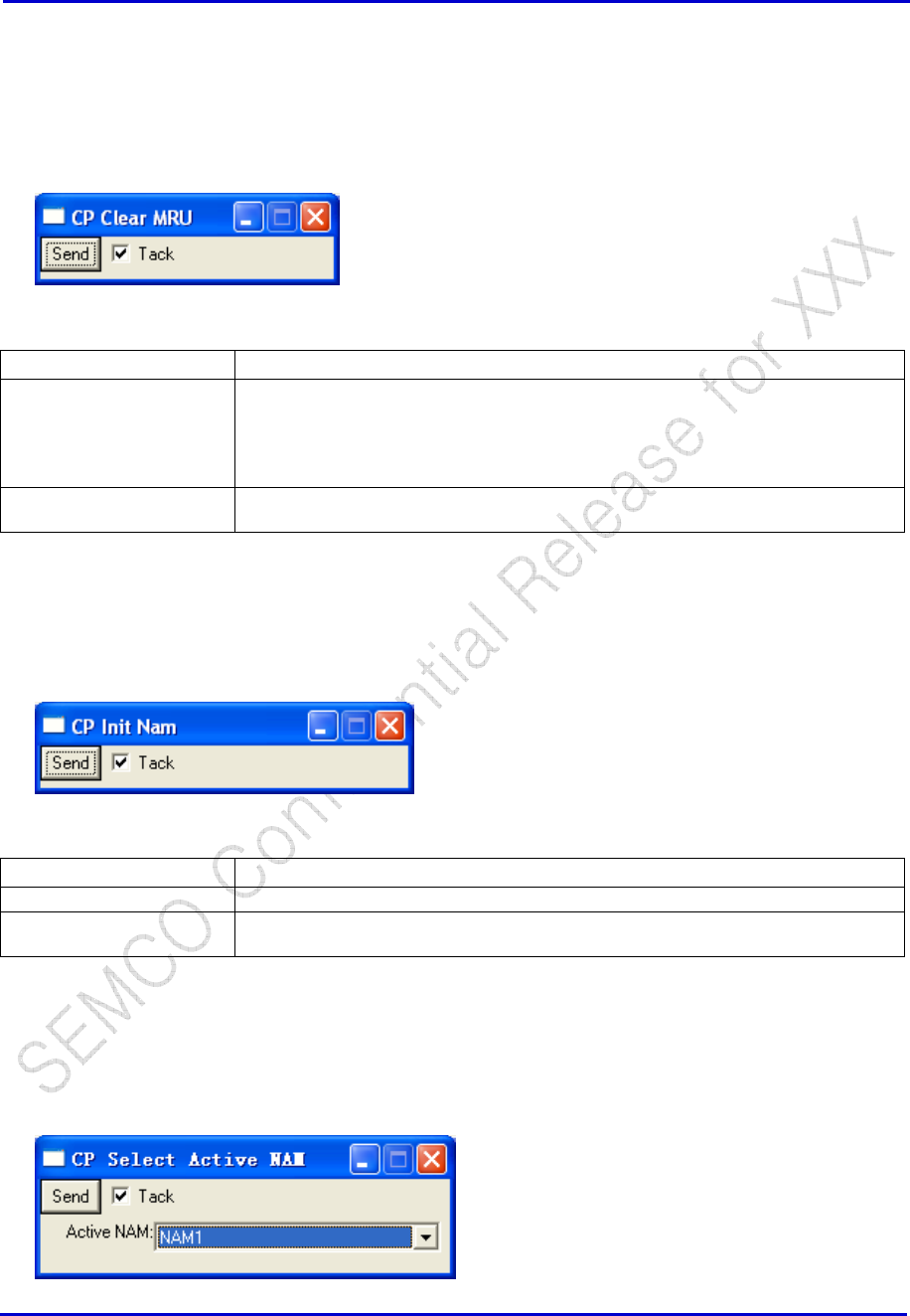
Samsung Electro-Mechanics Co., Ltd. Proprietary
REV 0
Samsung Electro-Mechanics Co., Ltd.
Proprietary Page 53
Clear MRU
CP → PS →Database→ CP Clear MRU
Window Selections Definition
Send The MRU (Most Recently Used Channels) is a list of (Band, Channel #) which is
stored in Flash. At Power Up the CBP4 software first scans the channels in the
MRU, and then goes to the PRL. Clearing the MRU ensures that the PRL will be
scanned first.
This command is particularly useful when a new PRL is downloaded to the phone.
Tack If checked, the window will remain after clicking “Send”. If not checked, window will
close after clicking “Send”.
Init NAM
CP → PS →Database→ CP Init Nam
Window Selections Definition
Send Initializes the NAM with default values
Tack If checked, the window will remain after clicking “Send”. If not checked, window will
close after clicking “Send”.
Select Active NAM
CP → PS → Database → CP Select Active NAM
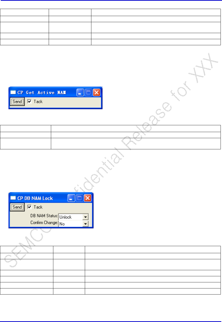
Samsung Electro-Mechanics Co., Ltd. Proprietary
REV 0
Samsung Electro-Mechanics Co., Ltd.
Proprietary Page 54
Window Selections Options Definition
Send -- Send to set the active NAM
Tack -- If checked, the window will remain after clicking “Send”. If not
checked, window will close after clicking “Send”.
Active NAM NAM1 Select “NAM1” as the active NAM
NAM2 Select “NAM2” as the active NAM
Get active NAM
CP → PS → Database → CP Get Active Nam
Window Selections Definition
Send Send to get the active NAM
Tack If checked, the window will remain after clicking “Send”. If not checked, window will
close after clicking “Send”.
NAM Lock, Unlock
CP → DB → CP DB NAM Lock
Window Selections Options Definition
Send Send to Lock/Unlock the Active NAM
Tack If checked, the window will remain after clicking “Send”. If not
checked, window will close after clicking “Send”.
DB NAM Status Lock This option locks the NAM and prevents modifications
Unlock This option unlocks the NAM and allows modifications
Confirm Change Yes Confirm the change you will perform
No
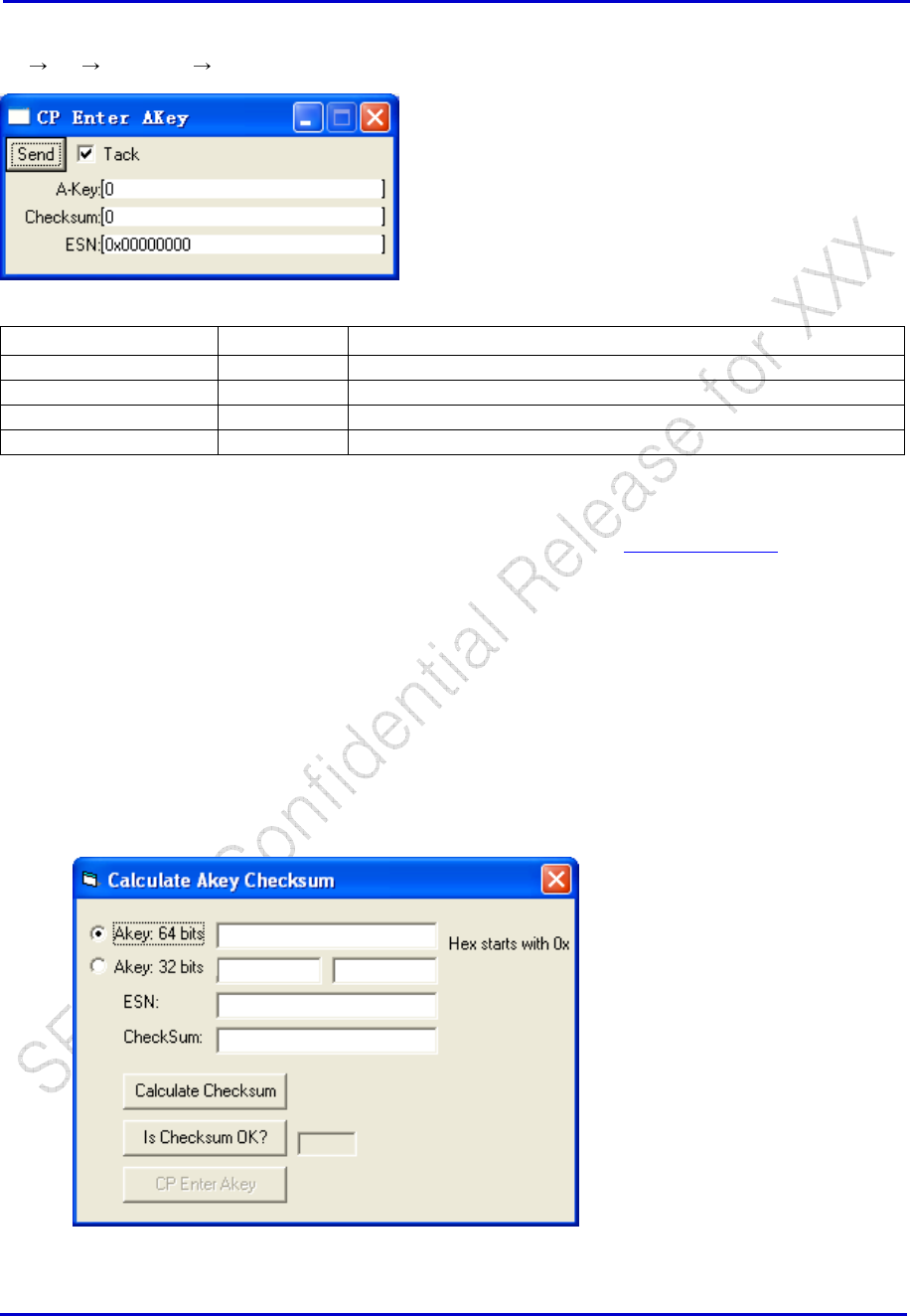
Samsung Electro-Mechanics Co., Ltd. Proprietary
REV 0
Samsung Electro-Mechanics Co., Ltd.
Proprietary Page 55
Set the A-Key
CP PS Database CP Enter A Key
Window Selections Options Definition
Send Send to write the A-Key
A-Key 20 decimal digit A-Key
Checksum 6 digit checksum
ESN 32-bit (8 hexadecimal) ESN
Some Notes Regarding this command:
1. The A-Key is only updated in the Active NAM. Therefore the Select Active NAM command
should be executed prior to this Akey command to explicitly select the NAM where the Akey
should be updated.
2. The ValidAkey field in the NAM is asserted after this command is executed
3. The entire Checksum of the NAM structure is updated after this command is executed. To
be explicit, please note that this NAM checksum is independent of the A-key checksum.
4. There is also a tool help you calculate A-Key checksum, find it from Utilities->A Key
Calculator. Put the Akey and ESN number into calculator, click “Calculate Checksum” .
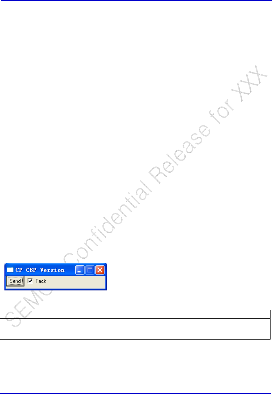
Samsung Electro-Mechanics Co., Ltd. Proprietary
REV 0
Samsung Electro-Mechanics Co., Ltd.
Proprietary Page 56
Data services
PRL
Voice Memo 1
Voice Memo 2
Voice Rec 1
Voice Rec 2
5.5.4 DB Clear, Flush, Cache
5.5.5 DB Write
5.5.6 DB Read
5.6 Software Operation Status
5.6.1 Software Version CP, DSPM, DSPV, ETS
CBP Version
CP → MON → CBP Version
Window Selections Definition
Send Send to Log Details of CBP version in the ETS Main Log Window
Tack If checked, the window will remain after clicking “Send”. If not checked, window
will close after clicking “Send”.
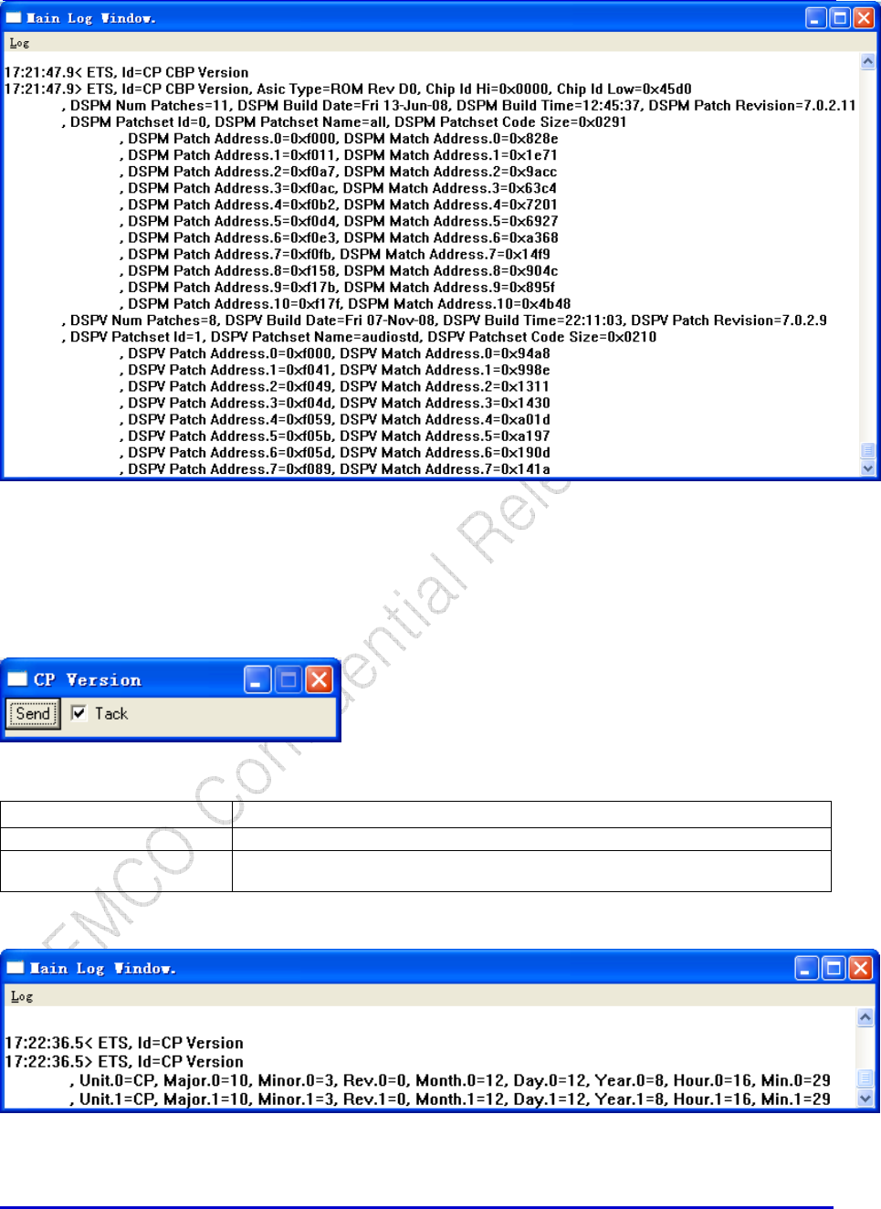
Samsung Electro-Mechanics Co., Ltd. Proprietary
REV 0
Samsung Electro-Mechanics Co., Ltd.
Proprietary Page 57
CP Version
CP → MON → CP Version
Window Selections Definition
Send Send to Log Details of CP Flash code in the ETS Main Log Window
Tack If checked, the window will remain after clicking “Send”. If not checked, window
will close after clicking “Send”.
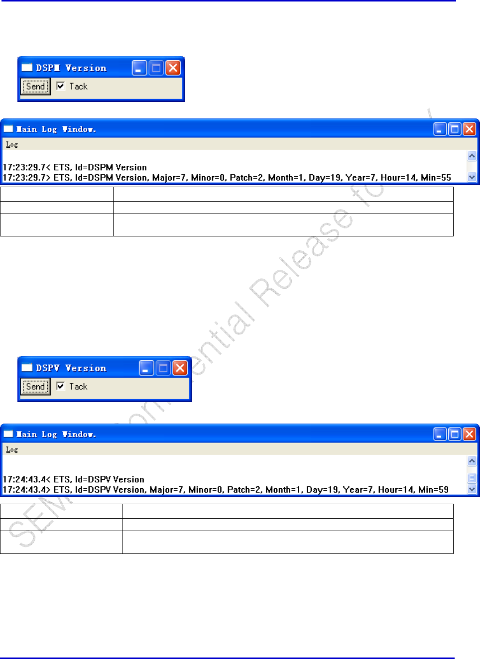
Samsung Electro-Mechanics Co., Ltd. Proprietary
REV 0
Samsung Electro-Mechanics Co., Ltd.
Proprietary Page 58
DSPM Version
DSPM → DSPM Version
Window Selections Definition
Send Send to Log Details of DSPM Flash code in the ETS Main Log Window
Tack If checked, the window will remain after clicking “Send”. If not checked, window will
close after clicking “Send”.
DSPV Version
DSPV →MON → DSPV Version
Window Selections Definition
Send Send to Log Details of DSPV Flash code in the ETS Main Log Window
Tack If checked, the window will remain after clicking “Send”. If not checked, window will
close after clicking “Send”.
ETS Version
Help → About EtsMain
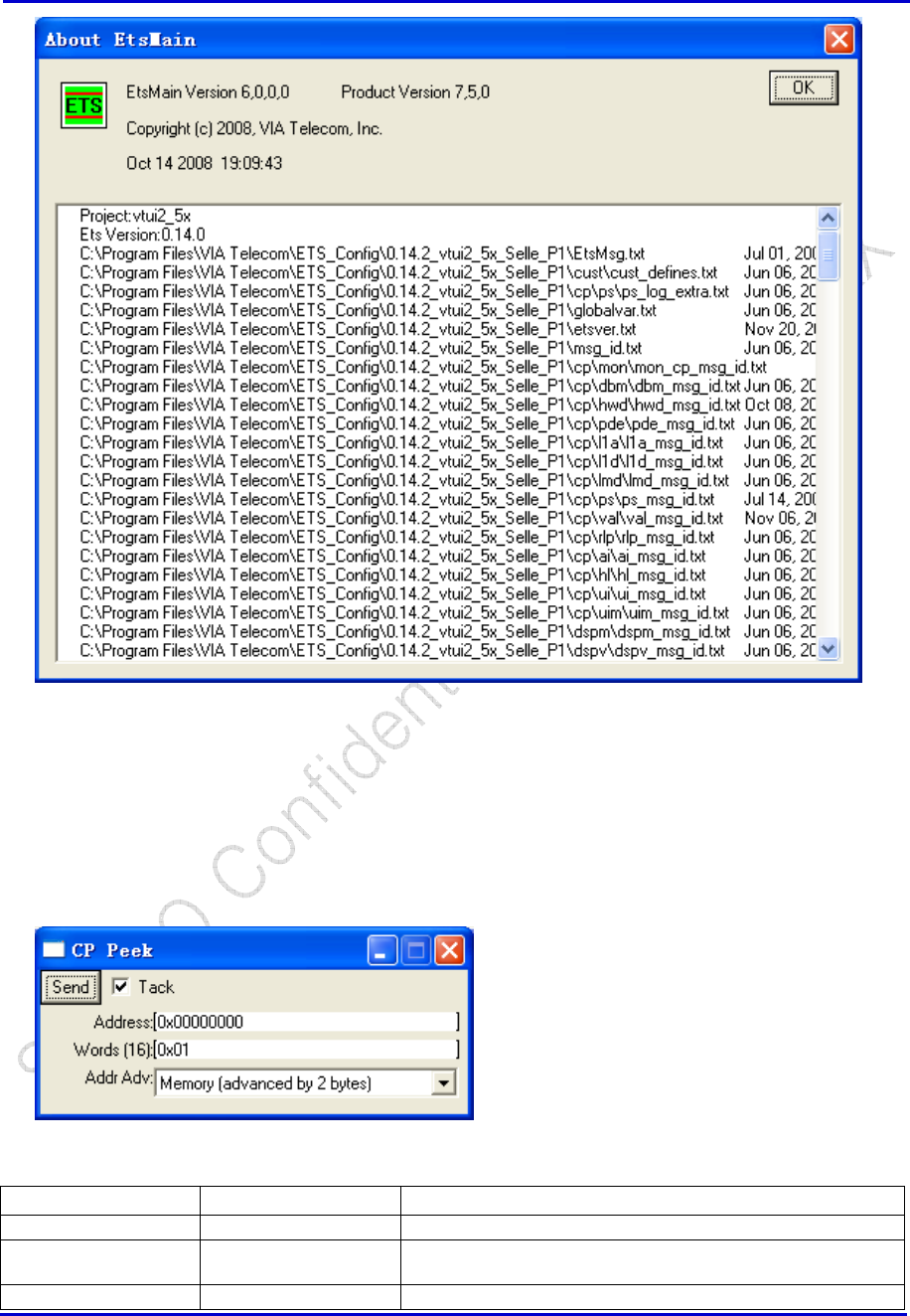
Samsung Electro-Mechanics Co., Ltd. Proprietary
REV 0
Samsung Electro-Mechanics Co., Ltd.
Proprietary Page 59
5.6.2 Memory Peek
CP Peek
CP → MON → CP Peek
Window Selections Options Definition
Send -- Send to Peek the CP Memory Location(s) or Register(s)
Tack -- If checked, the window will remain after clicking “Send”. If not
checked, window will close after clicking “Send”.
Address -- Address of CP Memory or Register
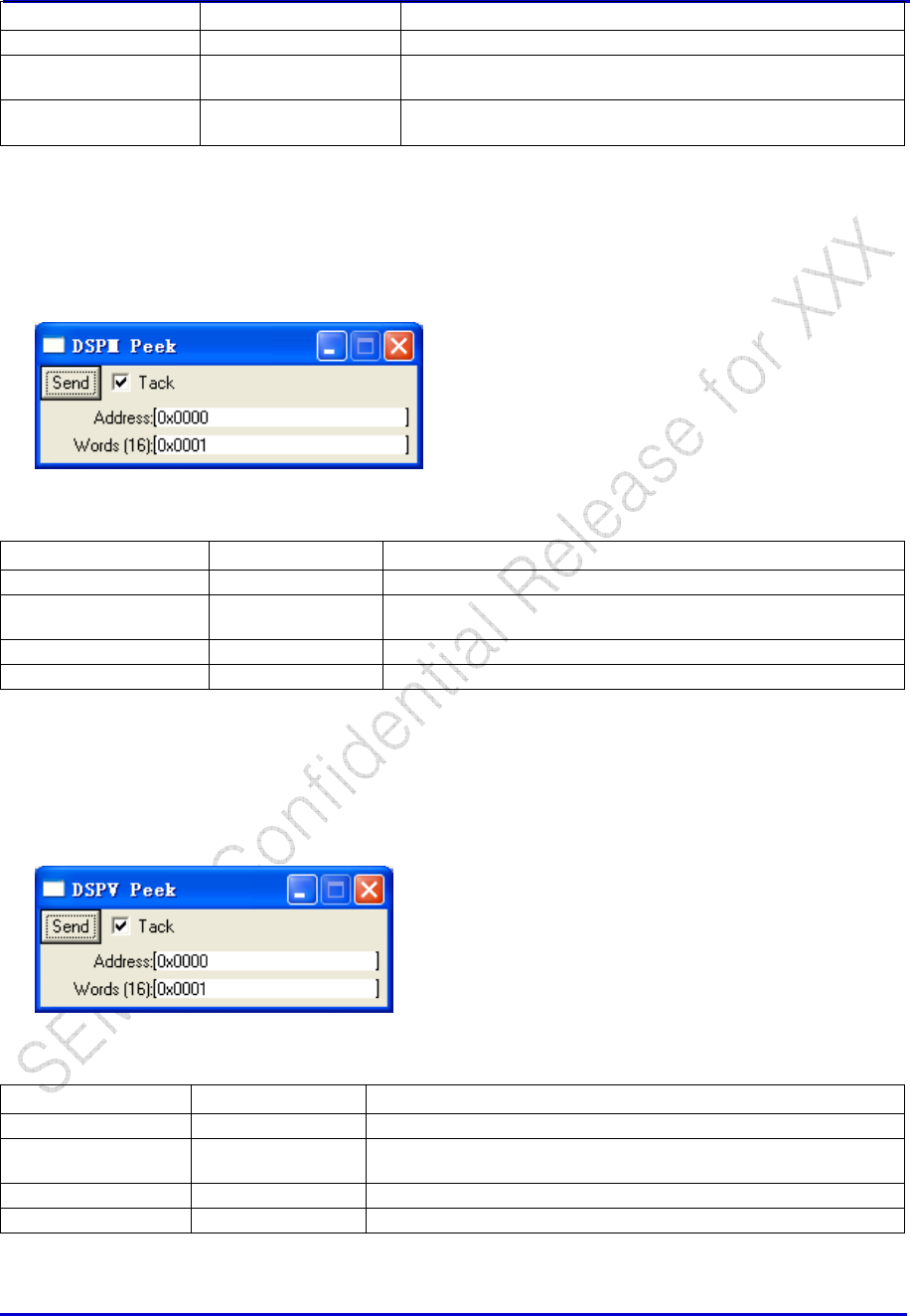
Samsung Electro-Mechanics Co., Ltd. Proprietary
REV 0
Samsung Electro-Mechanics Co., Ltd.
Proprietary Page 60
Window Selections Options Definition
Words(16) -- Number of words, up to 16 to Peek. Valid values: 1-16
Addr Adv Memory (advanced by
2 bytes)
Use this option to Peek Memory
Register (advanced by
4 bytes)
Use this option to Peek Registers
DSPM Peek
DSPM → DSPM Peek
Window Selections Options Definition
Send Send to Peek the DSPM Memory Location(s) or Register(s)
Tack If checked, the window will remain after clicking “Send”. If not
checked, window will close after clicking “Send”.
Address Address of DSPM Memory or Register
Words(16) Number of words, up to 16 to Peek. Valid values: 1-16
DSPV Peek
DSPV → MON → DSPV Peek
Window Selections
Options Definition
Send -- Send to Peek the DSPV Memory Location(s) or Register(s)
Tack -- If checked, the window will remain after clicking “Send”. If not
checked, window will close after clicking “Send”.
Address -- Address of DSPV Memory or Register
Words(16) -- Number of words, up to 16 to Peek. Valid values: 1-16
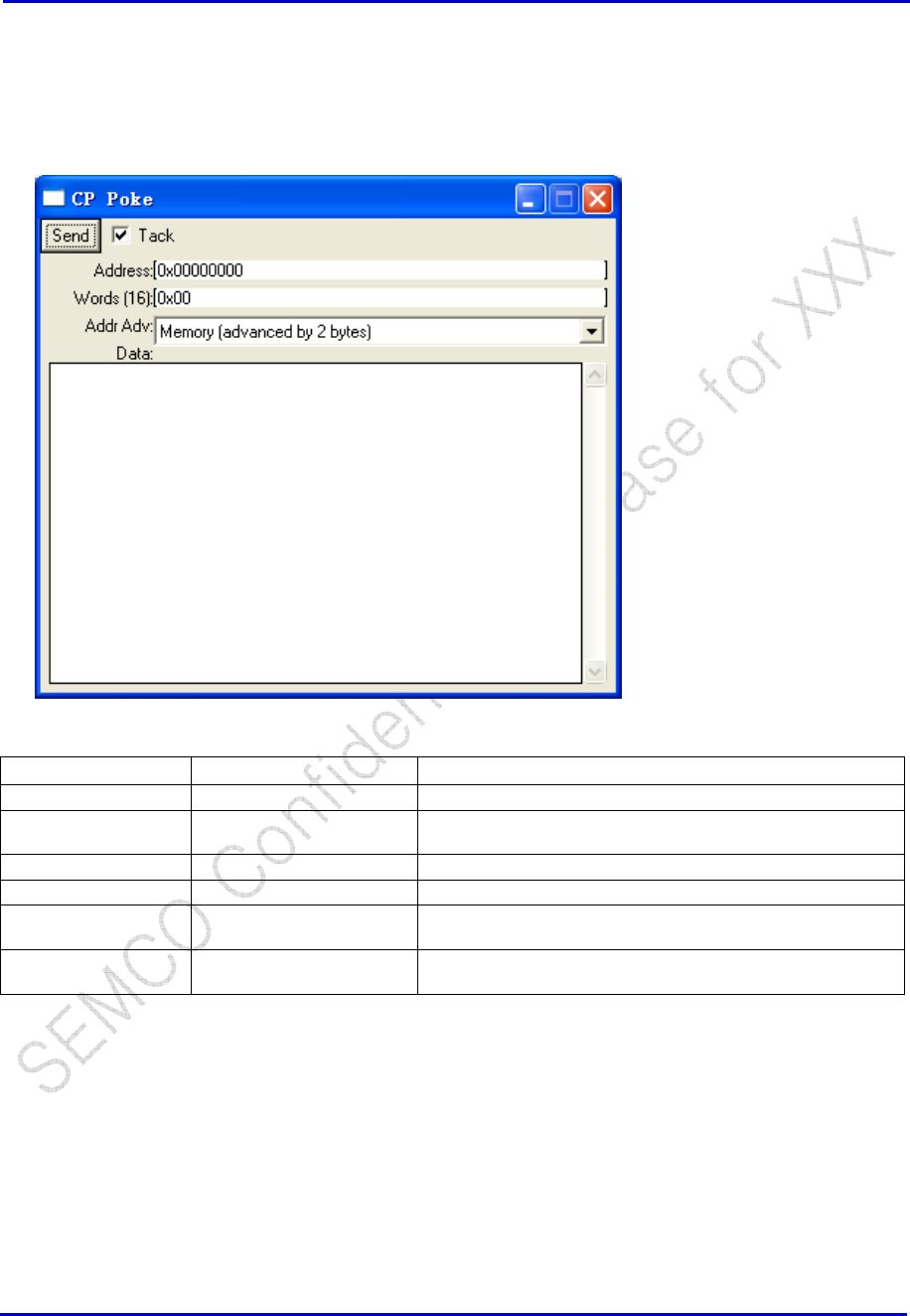
Samsung Electro-Mechanics Co., Ltd. Proprietary
REV 0
Samsung Electro-Mechanics Co., Ltd.
Proprietary Page 61
5.6.3 Memory Poke
CP Poke
CP → MON → CP Poke
Window Selections
Options Definition
Send -- Send to Poke the CP Memory Location(s) or Register(s)
Tack -- If checked, the window will remain after clicking “Send”. If
not checked, window will close after clicking “Send”.
Address -- Address of CP Memory or Register
Words(16) -- Number of words, up to 16 to Poke. Valid values: 1-16
Addr Adv Memory (advanced by 2
bytes)
Use this option to Poke Memory
Register (advanced by 4
bytes)
Use this option to Poke Registers
DSPM Poke
DSPM → DSPM Poke
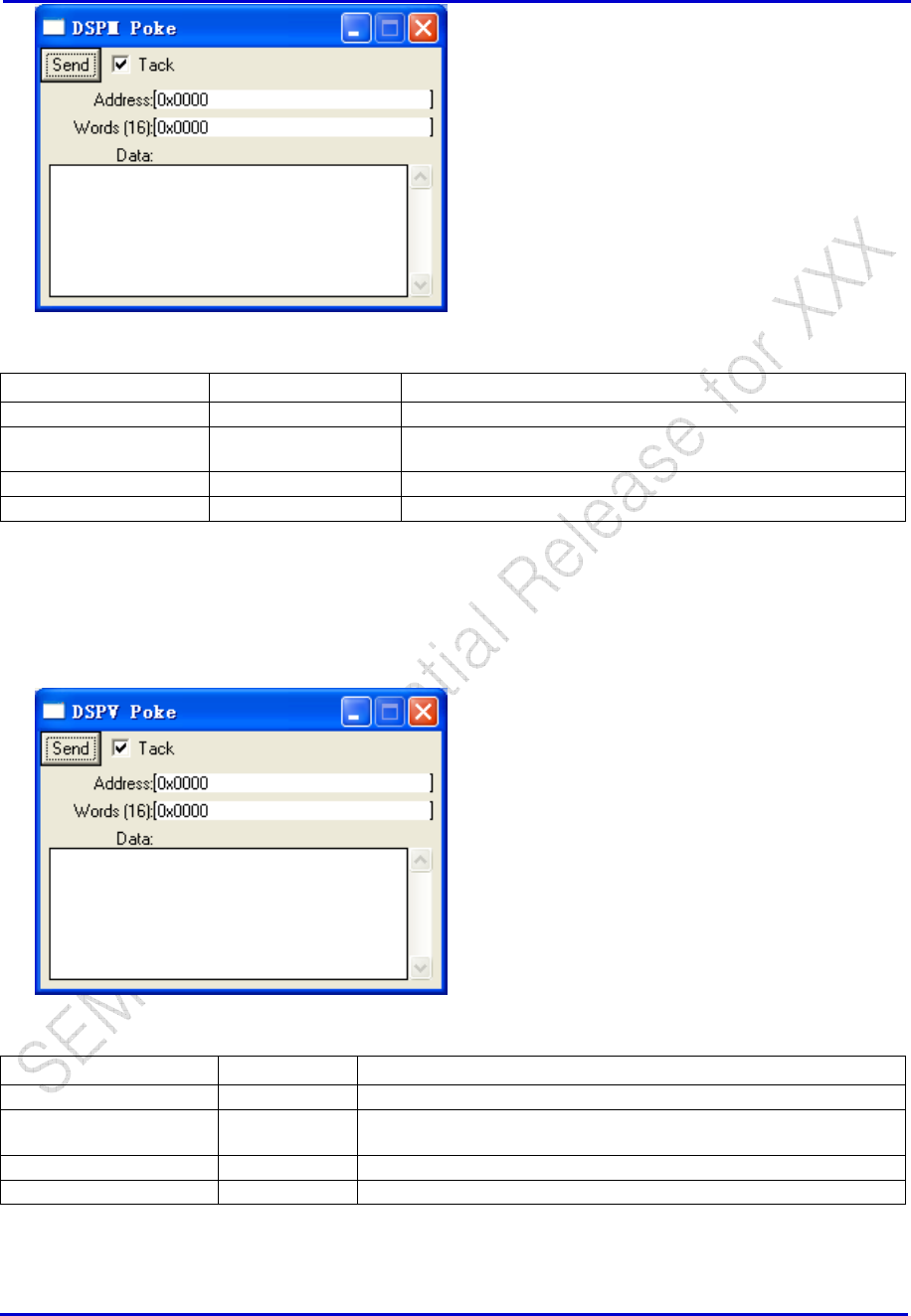
Samsung Electro-Mechanics Co., Ltd. Proprietary
REV 0
Samsung Electro-Mechanics Co., Ltd.
Proprietary Page 62
Window Selections Options Definition
Send Send to Poke the DSPM Memory Location(s) or Register(s)
Tack If checked, the window will remain after clicking “Send”. If not
checked, window will close after clicking “Send”.
Address Address of DSPM Memory or Register
Words(16) Number of words, up to 16 to Poke. Valid values: 1-16
DSPV Poke
DSPV → MON → DSPV Poke
Window Selections Options Definition
Send Send to Poke the DSPV Memory Location(s) or Register(s)
Tack If checked, the window will remain after clicking “Send”. If not
checked, window will close after clicking “Send”.
Address Address of DSPV Memory or Register
Words(16) Number of words, up to 16 to Poke. Valid values: 1-16
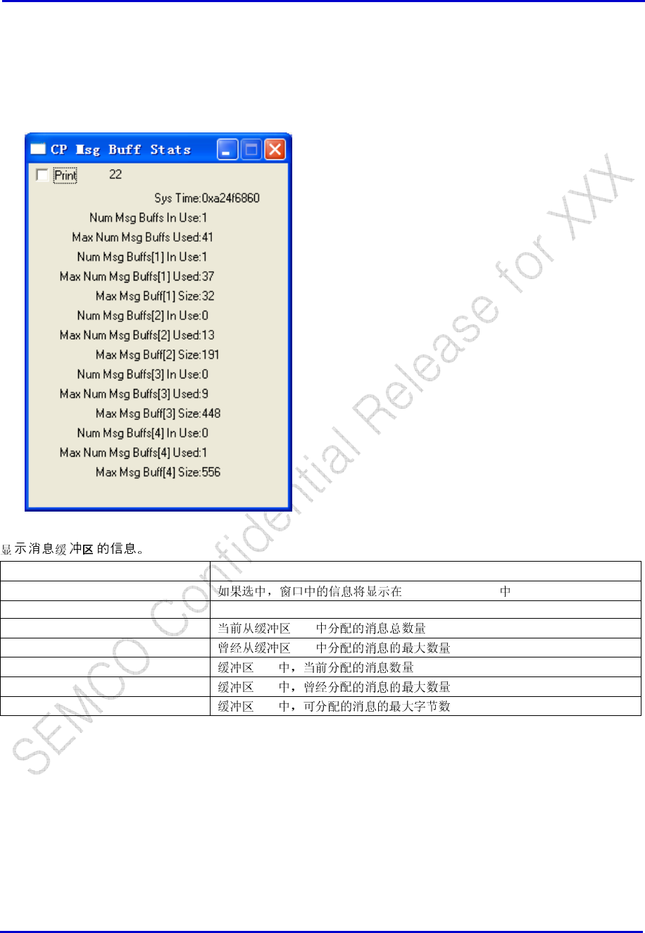
Samsung Electro-Mechanics Co., Ltd. Proprietary
REV 0
Samsung Electro-Mechanics Co., Ltd.
Proprietary Page 63
5.6.4 Disabling All Spies And Traces
5.6.5 Msgs Buffer Stats Spy
CP → Spy → MON → CP Msg Buff Stats
Window Display Description
Print main log window
Sys Time
Num Msg Buffs In Use 1-4
Max Num Msg Buffs Used 1-4
Num Msg Buffs[1:4] In Use 1-4
Max Num Msg Buffs[1:4] 1-4
Max Msg Buff[1:4] Size 1-4
5.6.6 Msgs Mbox Stats Spy
CP → Spy → MON → CP Msg Mbox Stats
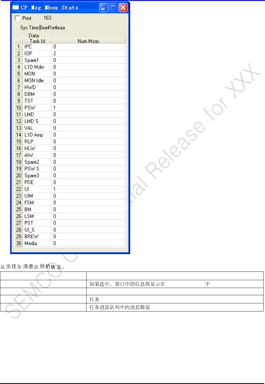
Samsung Electro-Mechanics Co., Ltd. Proprietary
REV 0
Samsung Electro-Mechanics Co., Ltd.
Proprietary Page 64
Window Display Explanation
Print main log window
Sys Time
Task Id ID
Num Msgs
5.6.7 Msgs Buf Ptr Stats Spy
CP → Spy → MON → CP Msg Buff Ptr Stats
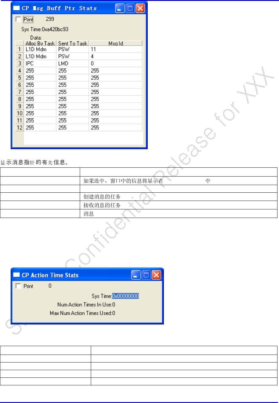
Samsung Electro-Mechanics Co., Ltd. Proprietary
REV 0
Samsung Electro-Mechanics Co., Ltd.
Proprietary Page 65
Window Display Explanation
Print main log window
Sys Time
Alloc By Task
Sent To Task
Msg Id ID
5.6.8 Action Time Stats
CP->Spy->MON->CP Action Time Stats
Window Display Explanation
Print
Sys Time
Num Action Times In Use
Max Num Action Times Used
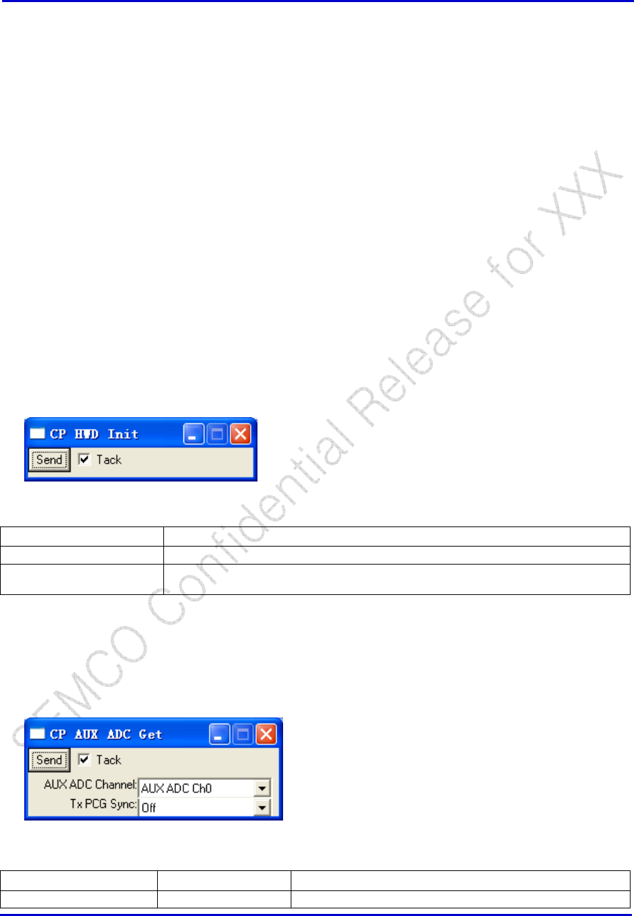
Samsung Electro-Mechanics Co., Ltd. Proprietary
REV 0
Samsung Electro-Mechanics Co., Ltd.
Proprietary Page 66
5.6.9 Clear TDSO Stats
5.6.10 Clear FER
5.7 CBP Hardware
5.7.1 HW Version
5.7.2 Reset Processor
CP, DSPM, DSPV
5.7.3 Initializing Hardware Control
5.7.4 Hwd Init
CP → HWD → HWD Init
Window Selections Definition
Send Send to Initialize Hardware Drivers
Tack If checked, the window will remain after clicking “Send”. If not checked, window will
close after clicking “Send”.
5.7.5 Aux ADC Get
CP → HWD → CP AUX ADC Get
Window Selections Options Definition
Send -- Send to Read the AUX ADC Channel
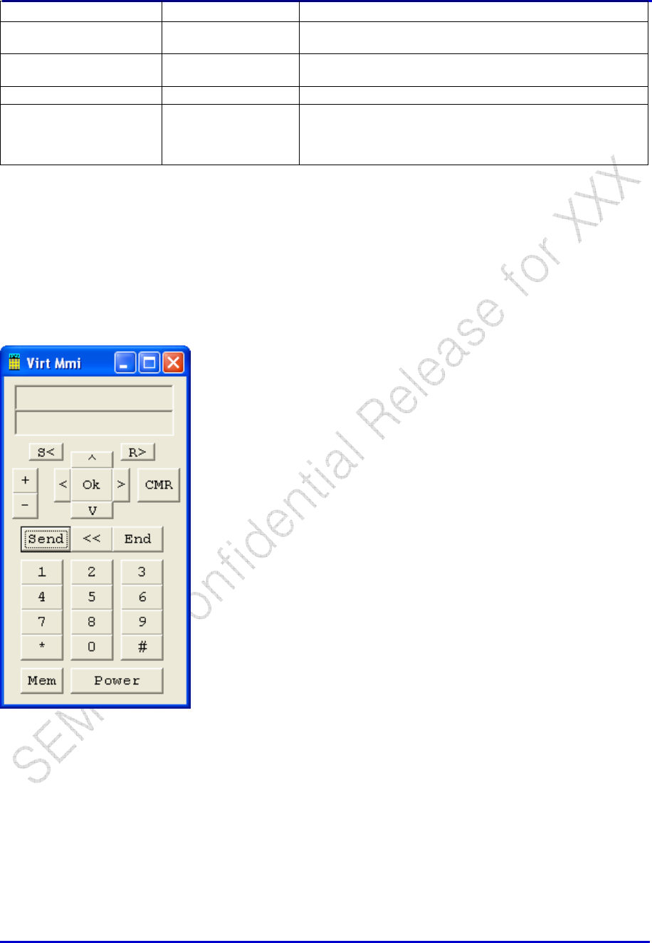
Samsung Electro-Mechanics Co., Ltd. Proprietary
REV 0
Samsung Electro-Mechanics Co., Ltd.
Proprietary Page 67
Window Selections Options Definition
Tack -- If checked, the window will remain after clicking “Send”. If
not checked, window will close after clicking “Send”.
AUX ADC Channel AUX ADC Ch[0-15] Read the Relevant AUX ADC Channel. There are 16
channels [0-15]
Tx PCG Sync Off Take the AUX ADC reading immediately
On Wait till an Active PCG to make a measurement. This is
especially usefully for measuring Transmit Power from the
Power Amplifier; selecting this option ensures that the
Power Amplifier is ON.
6 Utilities
6.1 Virtual MMI
Utilities -> Virtual MMI Utility, operate the handset just link press keypad.
6.2 Script Utility
Utilities -> Script Utility
The following steps descript how to record an ETS script. Give an example of record data of command
cp->DB->DB Templates->common->cp DB NAM 1, CP/DB/DB Templates/cellular/CP DB HWD Rx AGC.
1. Connect the phone to your computer, make sure all connection is ok.
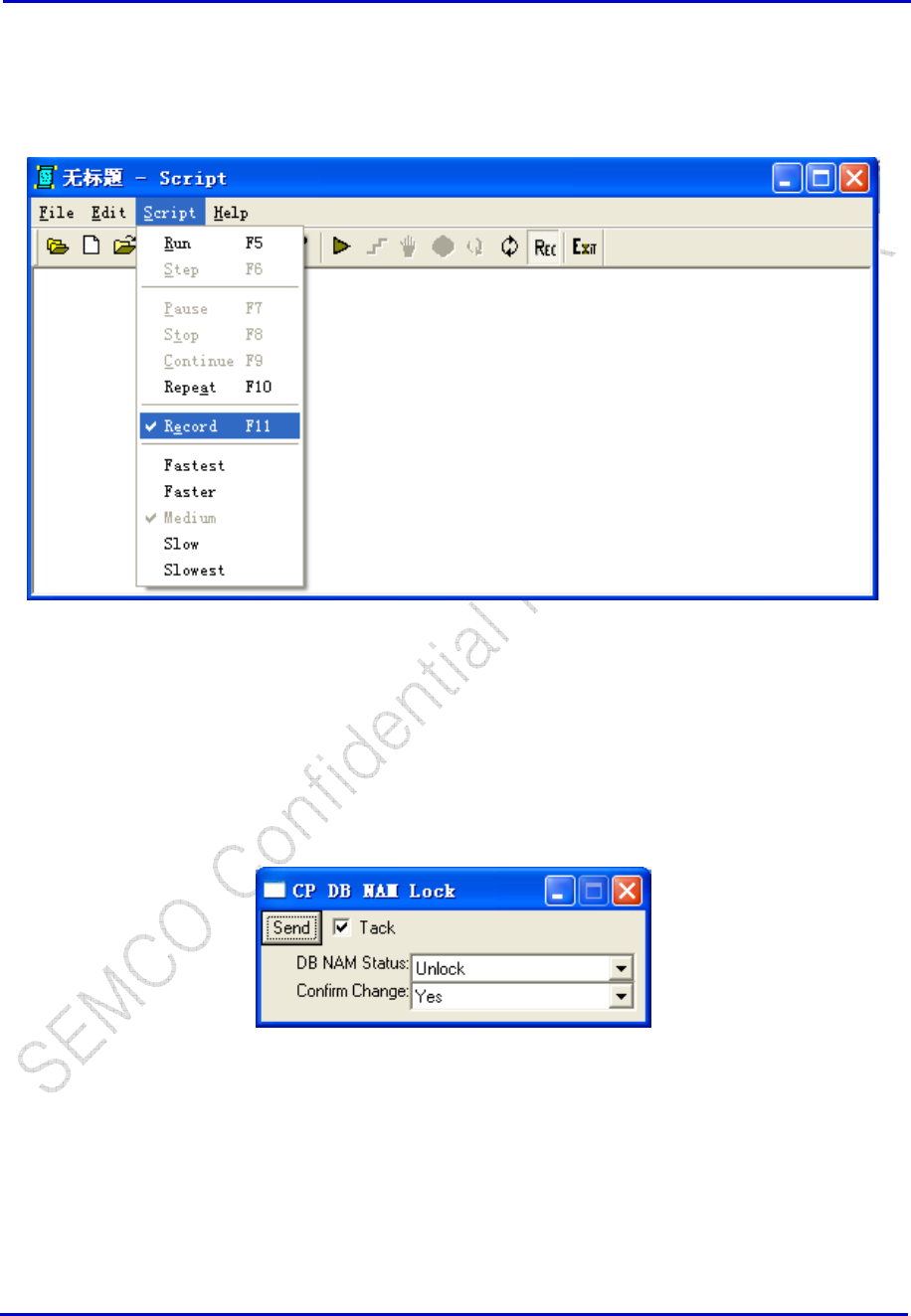
Samsung Electro-Mechanics Co., Ltd. Proprietary
REV 0
Samsung Electro-Mechanics Co., Ltd.
Proprietary Page 68
2. Open ETS.
3. Run script thru Utilities -> Script Utility. In the Script, Select Script->Record command to let
Script application in Recording status. Then Script.exe will record all commands that printed in ETS main
window.
4. In ETS application, select CP->DB->CP DB NAM LOCK command to unlock the NAM. Then select
CP->DB->DB Templates->common->CP DB NAM 1 command to open the dialog of CP DB
NAM1. And select CP->DB->DB Templates->BAND A->CP DB HWD BAND A Rx AGC to open
the dialog of CP DB HWED Rx AGC. If you want record more you can select the commands you want
to record.
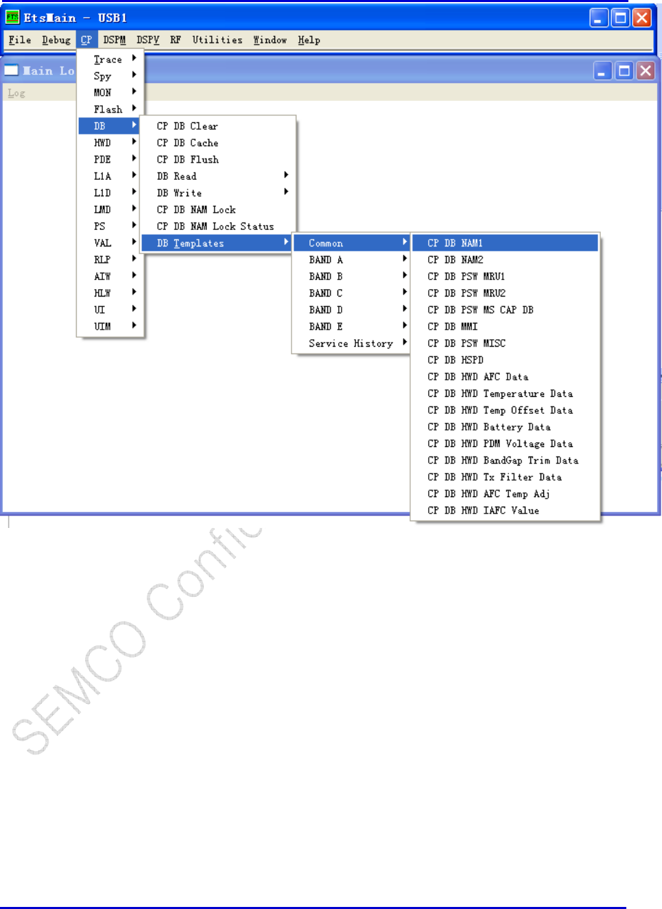
Samsung Electro-Mechanics Co., Ltd. Proprietary
REV 0
Samsung Electro-Mechanics Co., Ltd.
Proprietary Page 69
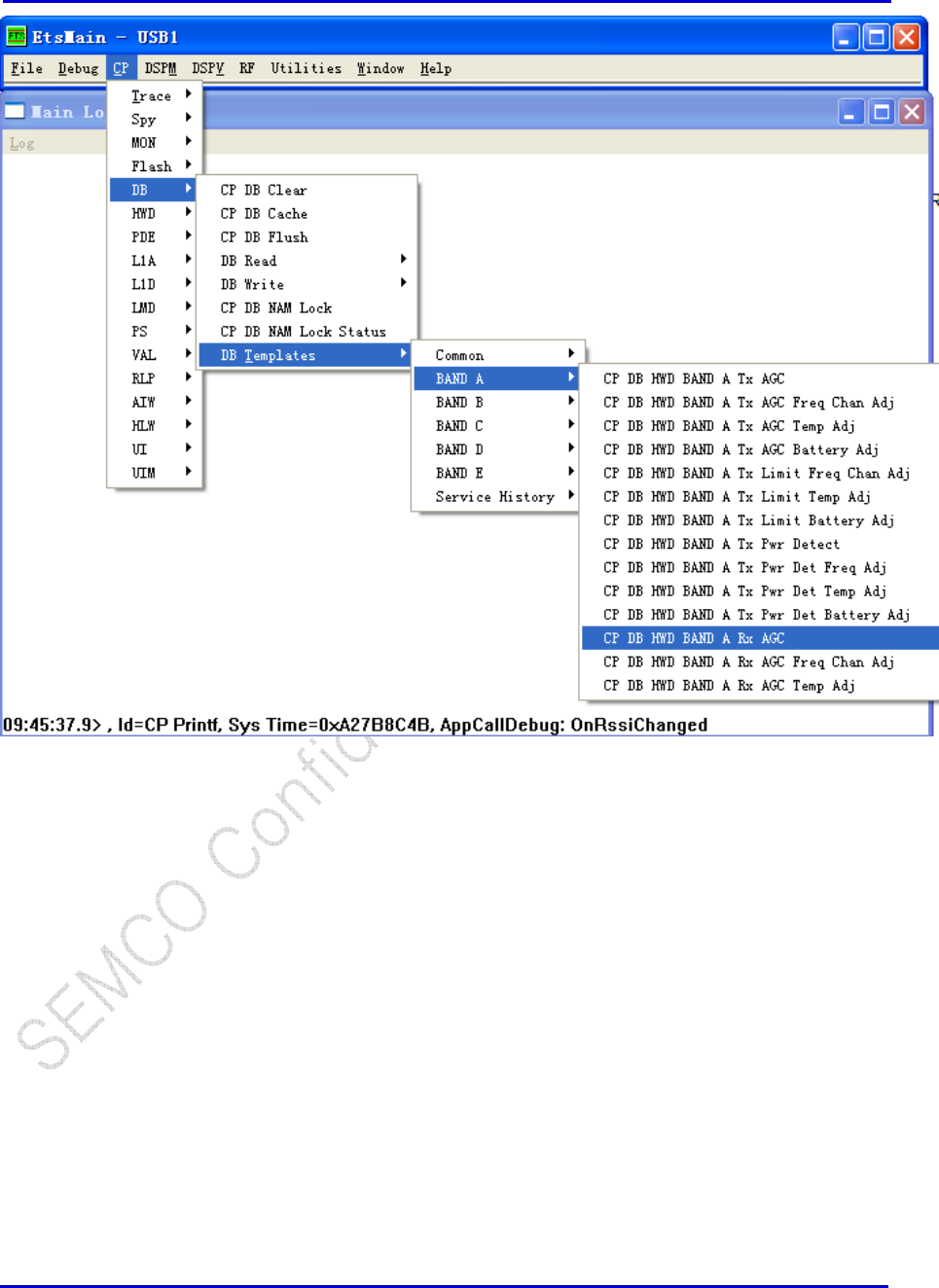
Samsung Electro-Mechanics Co., Ltd. Proprietary
REV 0
Samsung Electro-Mechanics Co., Ltd.
Proprietary Page 70
5. Click the “Read” commands in all dialog, For example In CP DB NAM1 dialog press the key “Read” to
read NAM1 data from the phone, and in “CP DB HWD BAND A Rx AGC “ dialog , press the key “Read”
to read Rx AGC data from the phone.
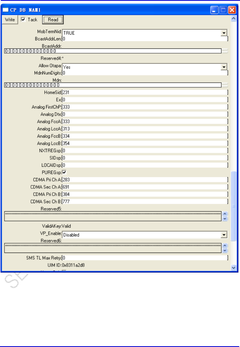
Samsung Electro-Mechanics Co., Ltd. Proprietary
REV 0
Samsung Electro-Mechanics Co., Ltd.
Proprietary Page 71
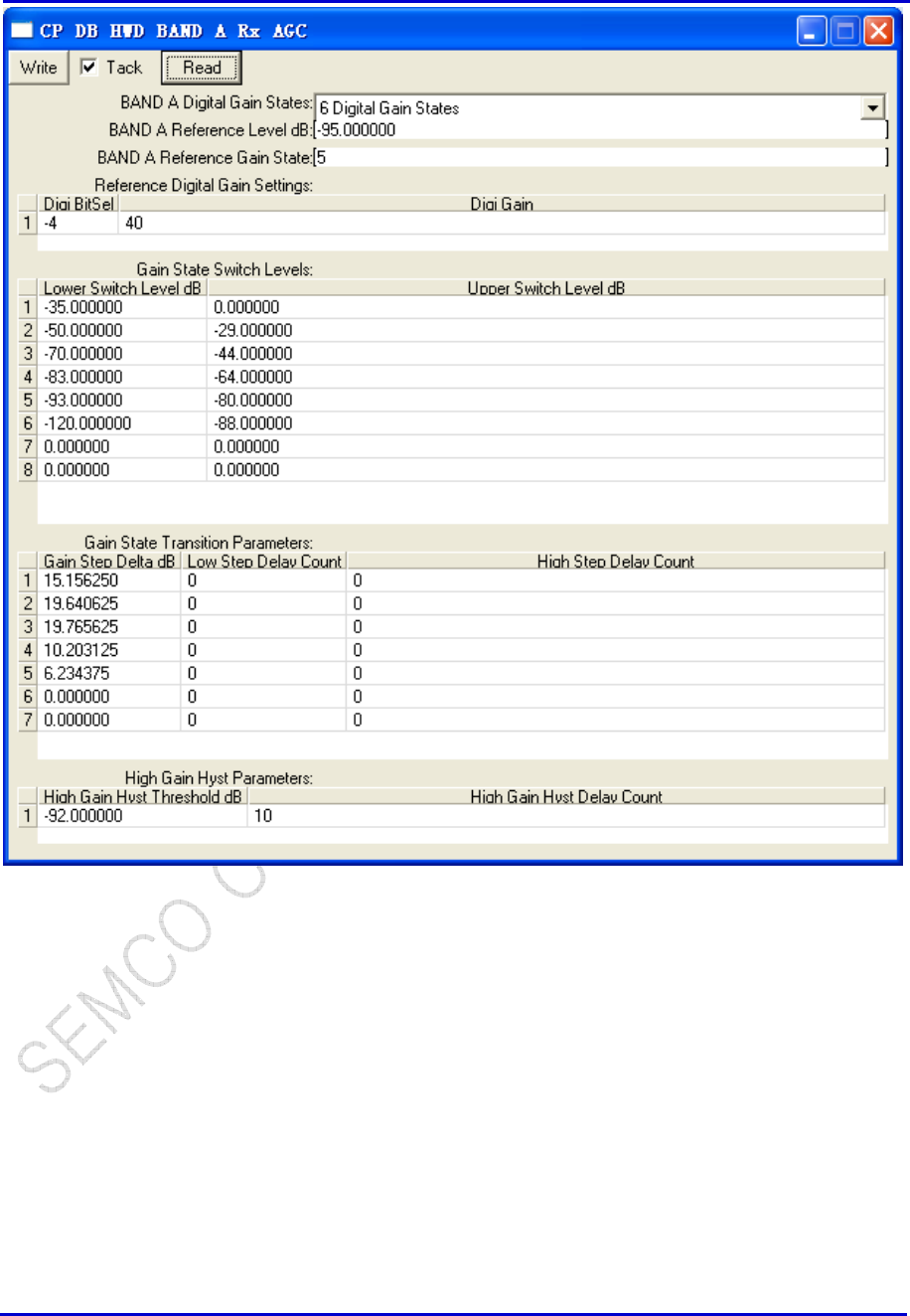
Samsung Electro-Mechanics Co., Ltd. Proprietary
REV 0
Samsung Electro-Mechanics Co., Ltd.
Proprietary Page 72
6. Then in ETS, click “Write” in all dialogs that you have opened. In CP DB NAM1 dialog press the key
“Write” to write NAM1 data into the phone, then this command will be printed in ETS main window
and be sent to Script.exe. It will be recorded in the Script.exe main window. In “CP DB HWD BAND A
Rx AGC “ dialog press the key “Write”, the Rx AGC data will be recorded into script main window.
(See Picture <4>)
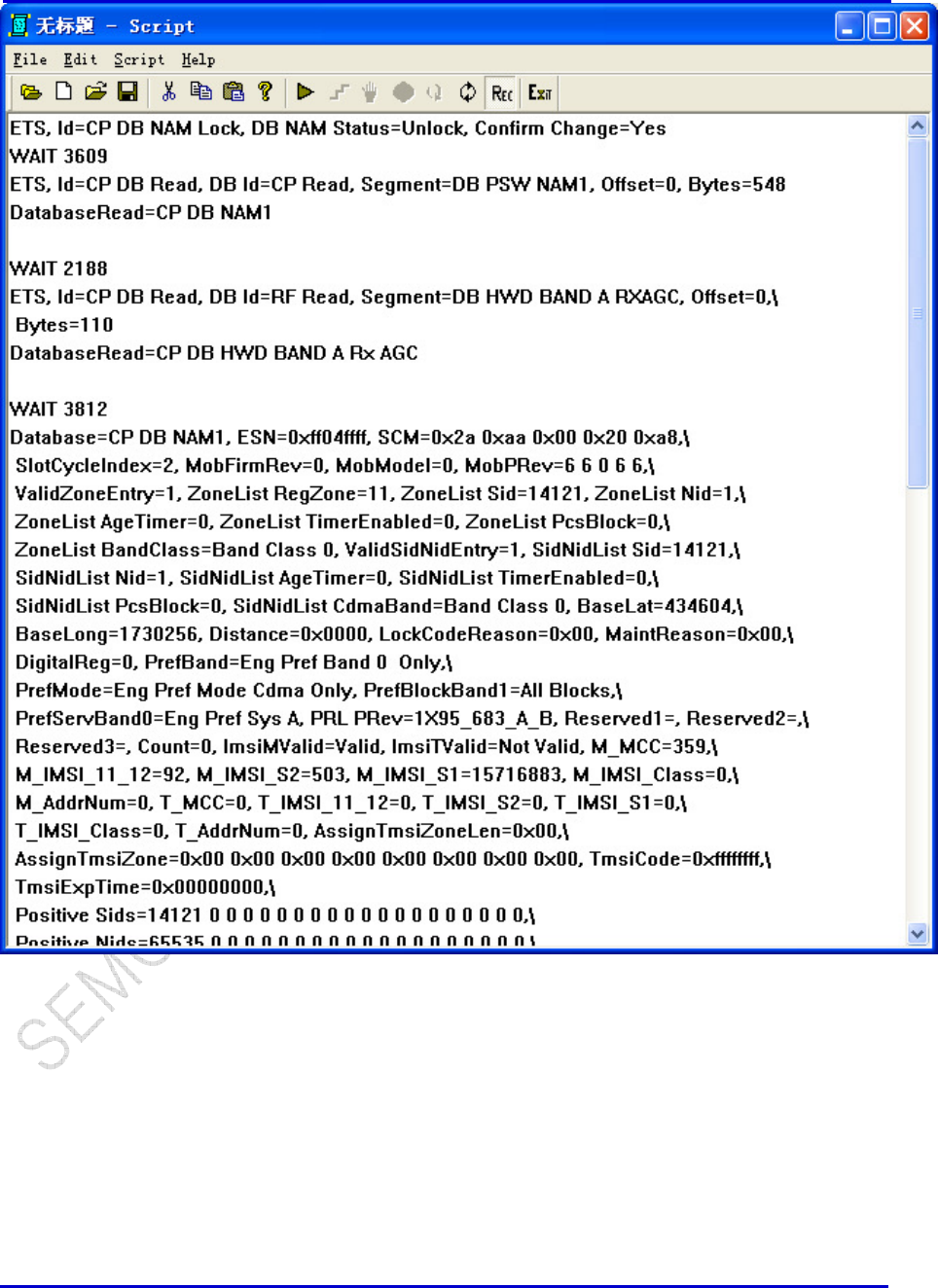
Samsung Electro-Mechanics Co., Ltd. Proprietary
REV 0
Samsung Electro-Mechanics Co., Ltd.
Proprietary Page 73
7. Switch to script, select Script->Record, to stop recording the script, and save the script in a file.
The file will be saved as *****.srp. Then you have recorded the NAM1 data in a script file.
Note: Usually if you want to run the write NAM data into the phone, you should set the NAM unlock.
So you need add the command “ETS, Id=CP DB NAM Lock, DB NAM Status=Unlock, Confirm
Change=No“ in the first line of script file. This command can also be directory recorded into script
file. The script file is TXT file, so you can edit it, copy some ETS command into the file.

Samsung Electro-Mechanics Co., Ltd. Proprietary
REV 0
Samsung Electro-Mechanics Co., Ltd.
Proprietary Page 74
Revision History
Revision Date Descriptions
1
20
12
-
0
6
-
0
5
Created
2
2