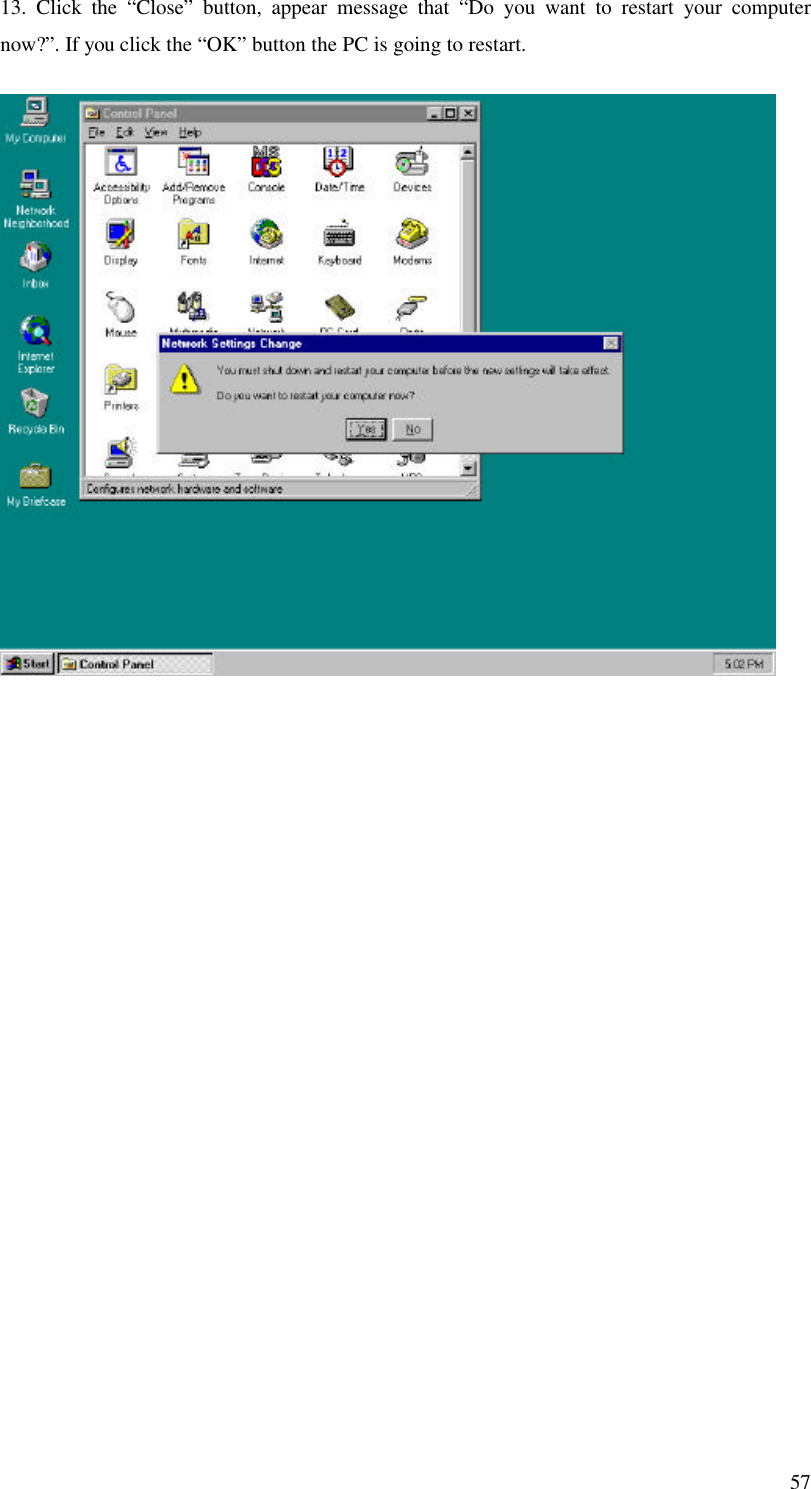
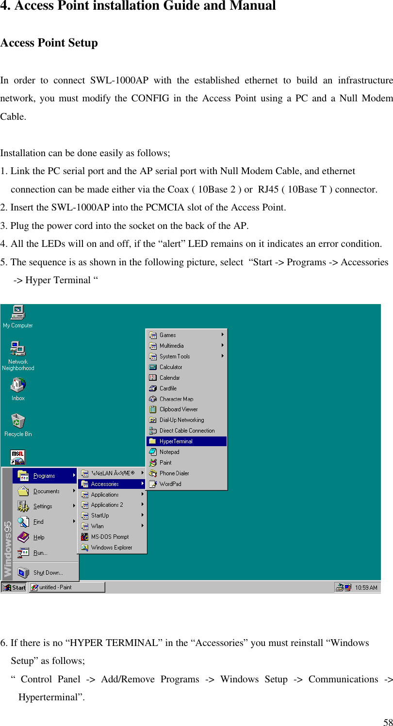
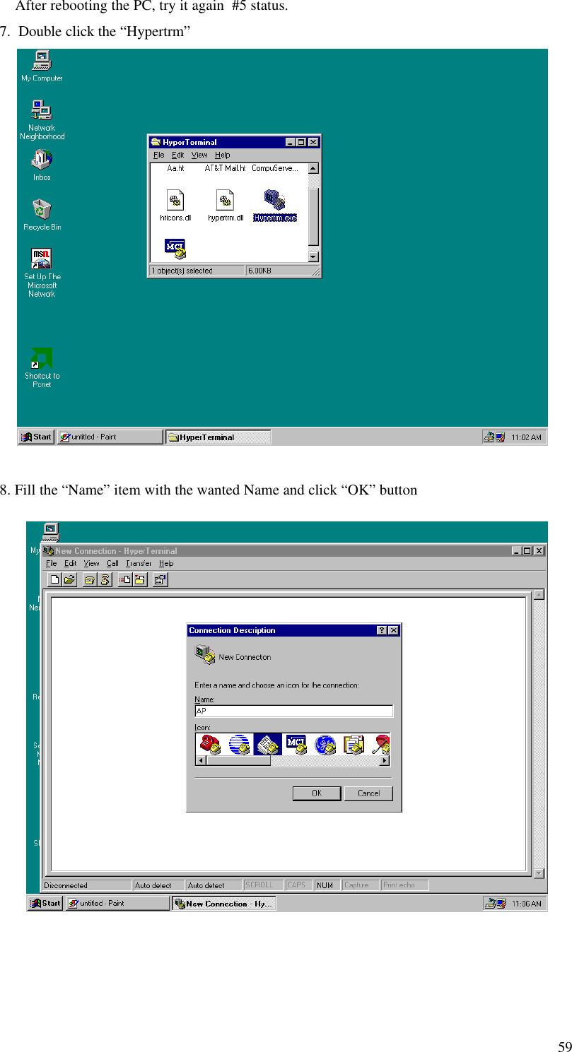
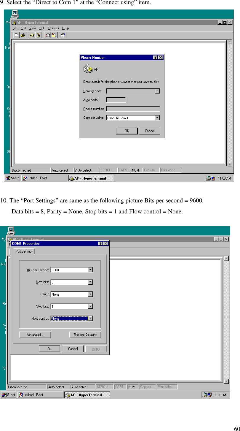
Samsung Electro Mechanics SWL-1000N PCMCIA LAN Card User Manual Manual
Samsung Electro Mechanics PCMCIA LAN Card Manual
UserManual.wiki
>
Samsung Electro Mechanics
>
SWL-1000N User Manual
>
manual
Contents
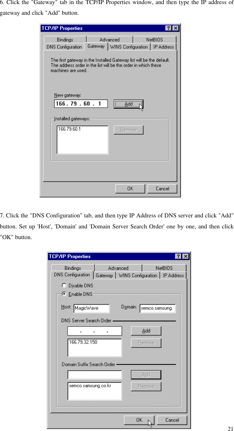
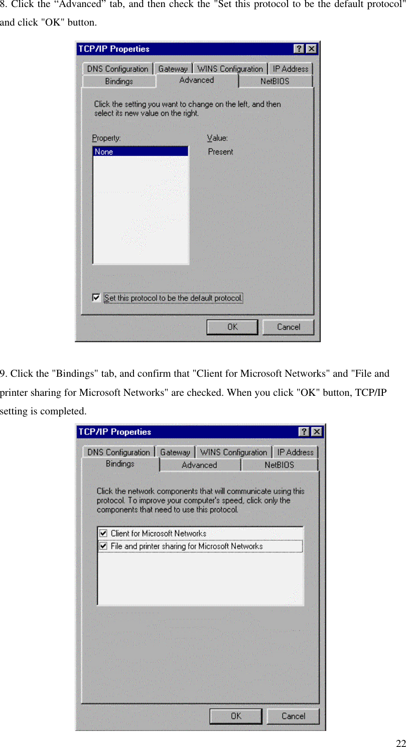
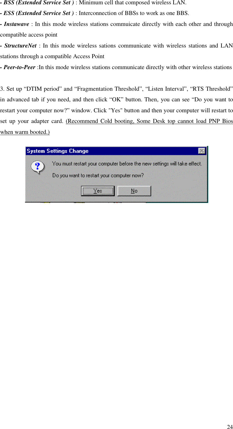
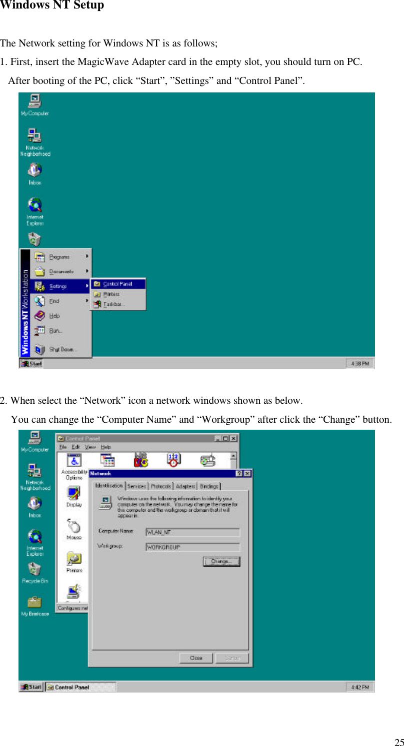
1.
manual
2.
8
manual
Navigation menu
Upload a User Manual
Namespaces
Wiki Guide
HTML
PDF
Info
Views
User Manual
Discussion / Help
Navigation