Samsung Electro Mechanics SWL-1000N PCMCIA LAN Card User Manual Manual
Samsung Electro Mechanics PCMCIA LAN Card Manual
Contents
- 1. manual
- 2. 8
manual

1
Table of Contents
0. Notice ……………………………………………………… 3
1. MagicWave Introduction ………………………………… 4
MagicWave Overview ..................................................….. 4
Main Characteristics ....................................................….. 5
Specifications ................................................................… 6
2. Network Installation ……………………………………... 8
Peer-to-Peer Mode ........................................................... 8
StructureNet Mode ................................................……... 9
3. Hardware and Software Installation ……………………. 10
Packing Contents .........................................................… 10
PC Configurations ........................................................... 11
Required Equipment for Network Connection ............….. 11
Hardware Installation ...................................................… 12
- Desktop PC adapter card ......................................… 12
- Notebook PC adapter card .....................................… 13
- Access Point .............................................................. 13
Software Installation ....................................................… 14
- Windows 95 / 98 Setup .............................................. 14
- Network Environment Setup .................................….. 18
- MagicWave Adapter Card Setup ...........................…. 23
- Windows NT Setup ...............................................…. 25
4. Access Point Installation Guide and Manual ………….32
Access Point Setup ......................................................… 32
Modify CONFIG.TXT ...............................................… 35
Null Modem Cable Configuration ...............................… 36
Parameter Descriptions ................................................… 37
- Radio Related ........................................................... 37
- Access Point Features ............................................… 37
- TCP/IP Parameters ................................................... 37
- Management Functions ……………………………. 38
- Diagnostic Method ………………………………….. 38
2
5. Management Utility ………………………………….40
Management Utility …………………………………… 40
Statistics Screen ……………………………………….. 41
Configuration Screen ………………………………….. 43
Wireless / LAN Screen ………………………………… 44
TELNET Command Management …………………….. 46
- Help Command …………………………………….. 47
- Bridge Commands …………………………………. 47
- System Commands ………………………………… 47
- Ping ………………………………………………… 48

3
Notice
The SWL-1000D and SWL-1000N complies with Part 15 of the FCC rules.
Operation is subject to the following two conditions;
(1) This device may not cause harmful interference.
(2) This device must accept any interference received, including
interference that may cause undesired operation.
Note : The SWL-1000N and SWL-1000D have been tested and found to comply
with the limits for a Class B digital device and a low power transmitter, according
to Part 15 of the FCC Rules. These limits are designed to provide reasonable
protection against harmful interference in a residential installation. This
equipment generates, uses and can radiate radio frequency energy and, if not
installed and used in accordance with the instructions, may cause harmful
interference to radio communications. However, there is no guarantee that
interference will not occur in a particular installation. If this equipment does
cause harmful interference to radio or television reception, which can be
determined by turning the equipment off and on, the user is encouraged to try to
correct the interference by one or more of the following measures;
- Reorient or relocate the receiving antenna.
- Increase the separation between the equipment and receiver.
- Connect the equipment into an output on a circuit different from that to
which the receiver is connected.
- Consult the dealer or an experienced radio/TV technician for help.
Service
MagicWave is the trademark of SAMSUNG in wireless LAN.
The most recent software and user documentation for all MagicWave products
are available on our World Wide Web.
http://www.sem.samsung.co.kr
Service Dept. 82-331-210-6805
Sales Dept. 82-331-210-6386

4
1. MagicWave Introduction
MagicWave Overview
The MagicWave(SWL-1000X) is a wireless LAN adapter card that provides wireless
connections between PC’s.
The function of the MagicWave SWL-1000AP (Access Point)is to transfer information from a
wired LAN to a wireless LAN and from the wireless LAN back to the wired LAN.
When operating, the MagicWave AP is invisible to most users (Normally, unless the user is an
administrator, the MagicWave AP can not be seen or accessed by users on the network).
The MagicWave is similar to Ethernet, a most widely used network card, but it can be used on
motion when applied to Notebook PC because of the wireless connection.
The MagicWave is designed to operate with IEEE802.11 compliant radio cards, wireless LAN
International Standard, and uses a protocol (CSMA/CA) of collision avoidance method for
protect a collision on the network, so a high speed communication is possible.
The MagicWave supports DSSS (Direct Sequence Spread Spectrum).
This is a radio technique which scrambles the data prior to transmission and uses a correlation
technique on receive to improve the signal to noise ratio and makes a possibility to
communicate in the office having a wall, a compartment.
The MagicWave provides network driver software to support most of the commonly used
network softwares and diagnostic programs.

5
Main Characteristic
The MagicWave supports a peer-to-peer communication which makes point-to-point and point-
to-multipoint communications possible, which makes the communications between wireless
LAN users easy.
A wireless network can be connected to a wired Ethernet through a network interface called an
Access Point. Since all the protocols for a wired network are supported through an Access
Point, all the services for a wired network are available for a wireless network users.
The MagicWave supports various network softwares. The network driver is supplied to support
most network softwares such as MS Windows for Workgroup3.11, Windows95, Windows NT
3.51 / 4.0, etc.
The SWL-1000N for Notebook PC is small and portable as a roaming function is provided for
users who need network services while maintaining mobility.

6
SPECIFICATIONS
♦ System Interface
♦ Radio Specifications
SWL-1000N SWL-1000D
Frequency 2412,2417,2422,2427
2432,2437,2442,2447 The same as SWL-1000N
2452,2457,2462,2467
2472,2484Mhz
Output Power less than 10mW/MHz less than 10mW/MHz
Transmission rate 2Mbps 2Mbps
Modulation Methods DSSS-DQPSK DSSS-DQPSK
Receive Signal Level -90dBm -90dBm
Main Lobe Bandwidth 22Mhz 22Mhz
FER less than 8*10E-2
♦ Transmission Range
SWL-1000N SWL-1000D
Medium Access Controller Am79c930 Am79c930
PC Interface PCMCIA ISA
Configuration Plug and Play Plug and Play
LAN Standard IEEE802.11 (CSMA/CA) IEEE802.11(CSMA/CA)
LAN Interface Radio Frequency Radio Frequency
SWL-1000N SWL-1000D
Outdoor 400m 420m
In the office having a 70m 70m
compartment ( About
1.5m height )
In the office having a 50m 50m
wall ( Not made of
concrete or metal )
In the office having a 30m 30m
wall made of concrete

7
♦ Physical Specifications
SWL-1000N SWL-1000D
Adapter card size 105*53*5mm 180*110*10mm
Antenna size built-in 85*80*15mm
Weight ( net ) 38g 145g
Operating temperature -10 ~ +50 °C
Power Consumption 1.6W 1.75W
u Supplied Software ( both SWL-1000N and SWL-1000D )
MS Windows for Workgroup 3.11( NDIS 2 ) / Windows 95 / Windows 98 /Windows NT3.51/
Windows NT4.0 driver
u Operating State Indication Lamp
¬ Power : SWL-1000D ( turns on when the system is powered on)
SWL-1000N ( turns on with beep sound when the PC
initializes the wireless LAN card in the PCMCIA slot on system booting ).
- Tx : turns on when transmitting data.
® Rx : turns on when receiving data.
A PCMCIA wireless LAN card automatically starts to operate when inserted into the slot while
the system is on because most notebook PC’s support hot plugging in the Windows 95
environment. To remove the card while the system is in operation follow the next steps:
2 Click on the icon shaped a PCMCIA card on the right bottom menu bar.
2 Click on the card removal message when it appears next to the icon.
2 Remove the card when the permission appears in a small box.
8
2. Network Installation
The number of computers connected, Ethernet installation, and desired network applications
determine the type of network, Ad-Hoc or Infrastructure.
The wireless LAN can easily be installed and used while one must connect cables to install a
wired LAN.
Peer- to - Peer Mode
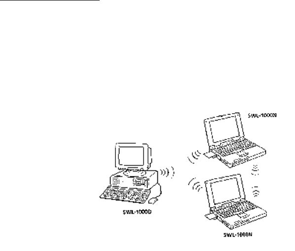
A peer-to-peer mode is suitable for the environment in which connections to wired network are
not necessary and can be constructed by only wireless LAN adapter cards.
You can use the network immediately after setting up the operating mode using the supplied
network driver.
9
StructureNet Mode
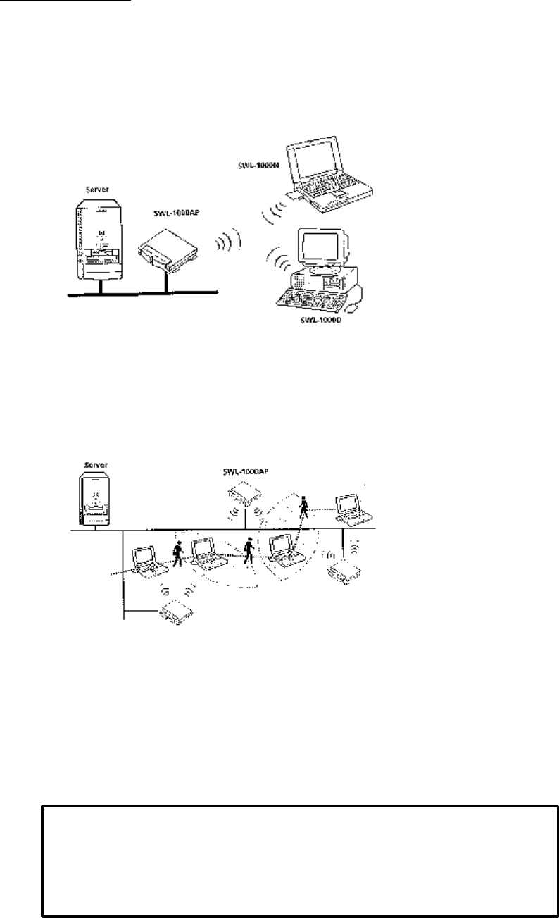
A wireless LAN can be used to access all the services that are available for a wired LAN
through an access point which connects the wireless LAN to a wired network.
Roaming function is also supplied to users who need mobile capabilities in this mode.
Roaming is a service that disconnects the user from an access point allotted to the
previous cell and connects to the one allotted to a new cell when the user moves into
the cell.
10
3. Hardware and Software installation
After opening the box, verify that all parts are included and check your computer and network
environment.
Packing Contents
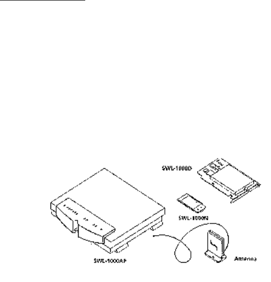
(1) SWL-1000N (PCMCIA Card) or SWL-1000D (ISA Card)
(2) SWL-1000AP (Each Access Point requires a SWL-1000N adapter card for operation)
(3) User’s Manual
(4) SWL-1000 Install Diskette (Driver Diskette)
(5) Power Adapter (SWL-1000AP only)
(6) SWL-1000AP Utilities Diskette (SWL-1000AP only)
(7) External Antenna (SWL-1000D only)

11
PC Configurations
For the SWL-1000D, verify that your computer has an extra IRQ, I/O Address.
SWL-1000D is ISA Plug & Play card supporting IRQ 9, 10, 11, 12.
Some multimedia PC may not have an extra IRQ.
Required Equipment for Network Connection
l If you want to use Peer-to-Peer Network, you can install with only SWL-1000D,
SWL-1000N adapter cards.
l If you want to use StructureNet Network, you must install Access Point (SWL-1000AP)
first.
Equipment required to install Access Point is
(1) Access Point (SWL-1000AP)
(2) PCMCIA wireless LAN adapter card (SWL-1000N)
(3) Power adapter.

12
Hardware Installation
Desktop PC Adapter Card ( SWL-1000D )
(1) Turn the PC off, uncover the case, and remove the Dummy Bracket of an empty
ISA expansion slot.
(2) Insert carefully a MagicWave wireless LAN card to the PC slot and insert the screw to
mount it in place.
(3) Then, insert the antenna to the antenna connected from the back of the PC card as shown
in the following picture.
(4) Turn the PC on and confirm that the adapter card is recognized by the PC by
checking the LED before you put the cover over the PC.
2 Verification procedure through LED
Red LED : power LED, lights when the computer turns on.
Orange LED : blinks when receiving data.
Green LED : blinks when transmitting data.
2 A SWL-1000D supports ISA Plug and Play. The card is automatically recognized and
installed in Windows 95 environment.
If your system does not support the Plug and Play, you can use the utility for ISA PnP
( not included in the package )

13
Notebook PC Adapter Card ( SWL-1000N )
You can insert the card into a Notebook PC while the power is on or off.
l When inserting the card while using your notebook PC
Insert the SWL-1000N adapter card into the PCMCIA slot. A pleasant “cheep” sound
indicates the regular operation. A low monotonous tone indicates a failure of the
recognition.
l When inserting the card before turning your notebook PC on.
The success or failure of the card recognition is also indicated by the sound as above.
If the card is successfully recognized, install the device driver following the instructions
on page 14.
Access Point ( SWL-1000AP )
A MagicWave Access Point connects a MagicWave wireless LAN to existing wired LAN.
An Access Point is equipped with an Ethernet adapter supporting 10base-T, 10base 2 and a
MagicWave wireless LAN adapter card.
Installation can be done easily as follows;
1. Insert the MagicWave card (SWL-1000N) into the PCMCIA slot of the Access Point
(SWL-1000AP)
2. Connect the network cable to Ethernet port (10base-T or 10base 2) on the back
of the Access Point.
3. Connect the power adapter.
14
Software Installation
Windows 98/95 Setup
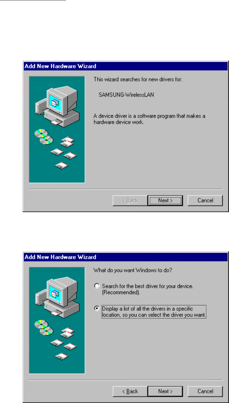
1. You can see the following message when you insert MagicWave adapter card on the PC slot.
(As previous presentation, in case of SWL-1000N for Notebook PC, you can insert a SWL-
1000N card while power is on or off. In case of SWL-1000D for desktop-PC, you turn on the
desktop-PC after you insert a SWL-1000D card on the PC slot.) Click “Next” button
2. Select “Display a list of…..” radio button, Click “Next” button
15
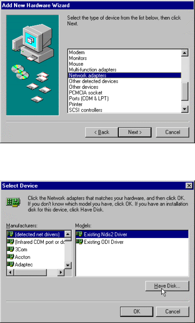
3. Select “Network adapters”, Click “Next” button
4. Select “(dectected net drivers)” in Manufacturers, and “Existing Ndis2 Driver” in Models
Click “Have Disk” button.
16
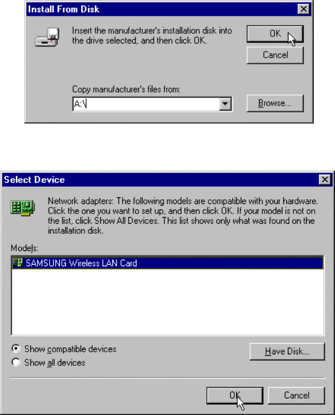
5. Insert the driver diskette offered with a card. Set “A:\”, Click “OK” button
6. Follwing window appears, click “OK” button
17
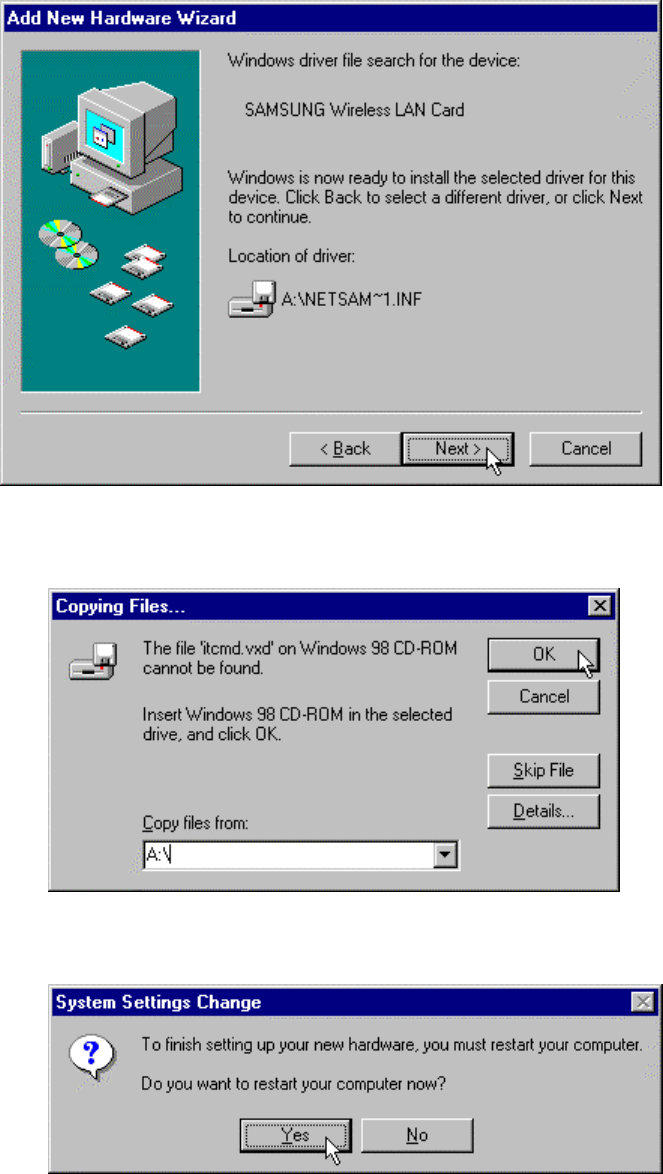
7. Follwing window appears, click “Next” button.
8. Following window appears, type “A:\” in Copy files from: Box, then click “OK” button
9. Restart your computer to finish setting up.
18
Network Environment Setup
After hardware and driver installations are finished, network environment setting for Windows
98 is needed. The steps are following.
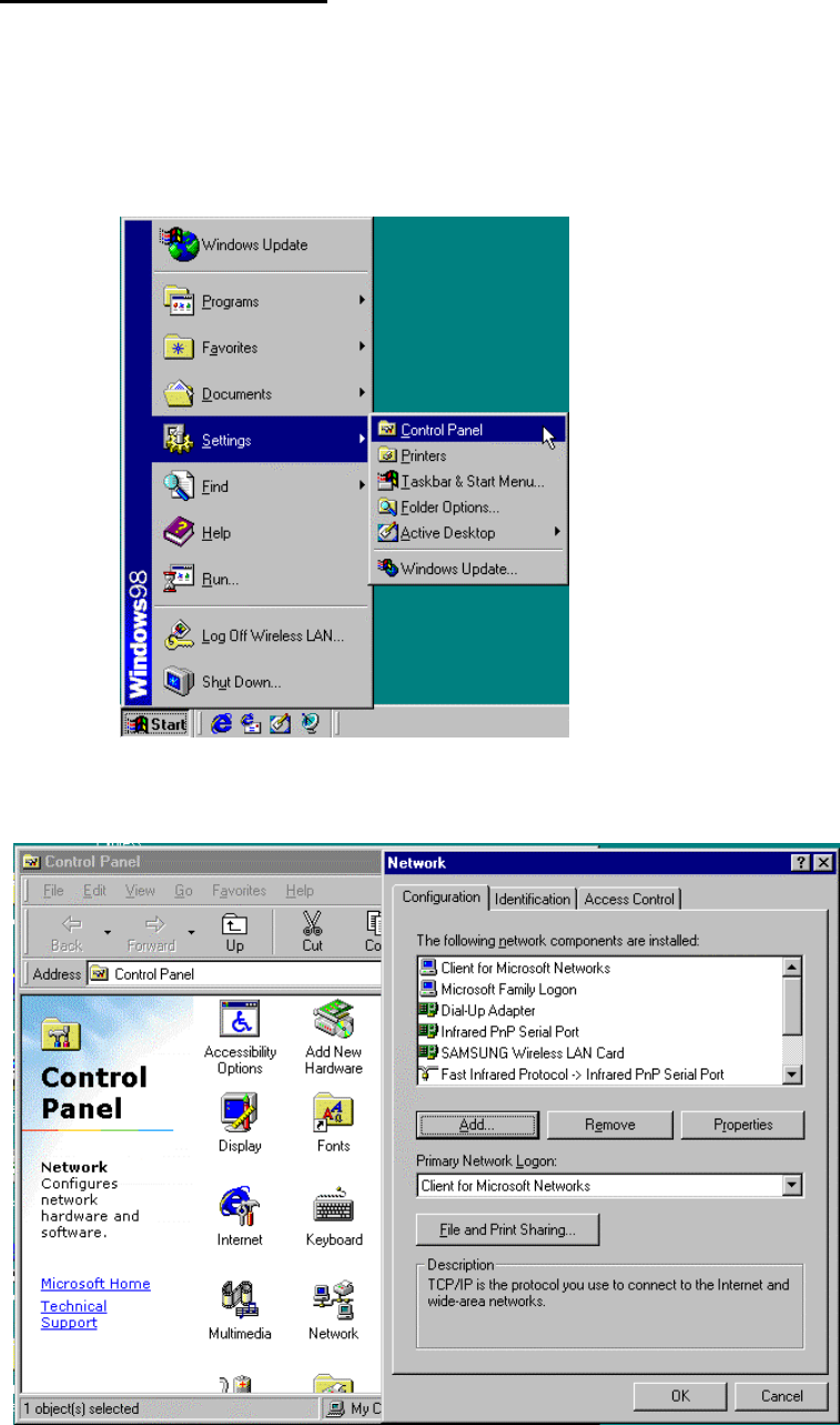
1. After restarting a computer, Click "Start", "Settings", and "Control Panel".
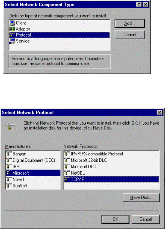
2. Double-click "Network" icon, then Network window appears, and click "Add" button.
19
3. When "Select Network Component Type" window appears, Click "Protocol", and click
"Add" button.
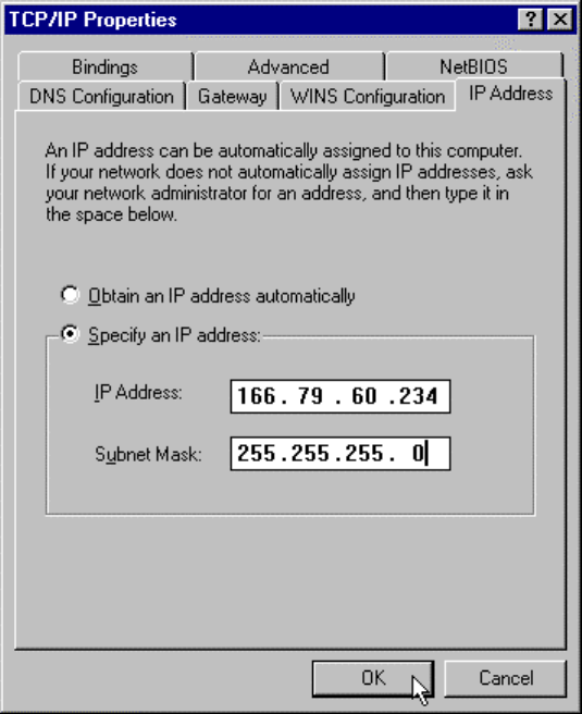
4. When "Select Network Protocol" window appears, Click "Microsoft" and "TCP/IP", and
then click "OK" button.
20
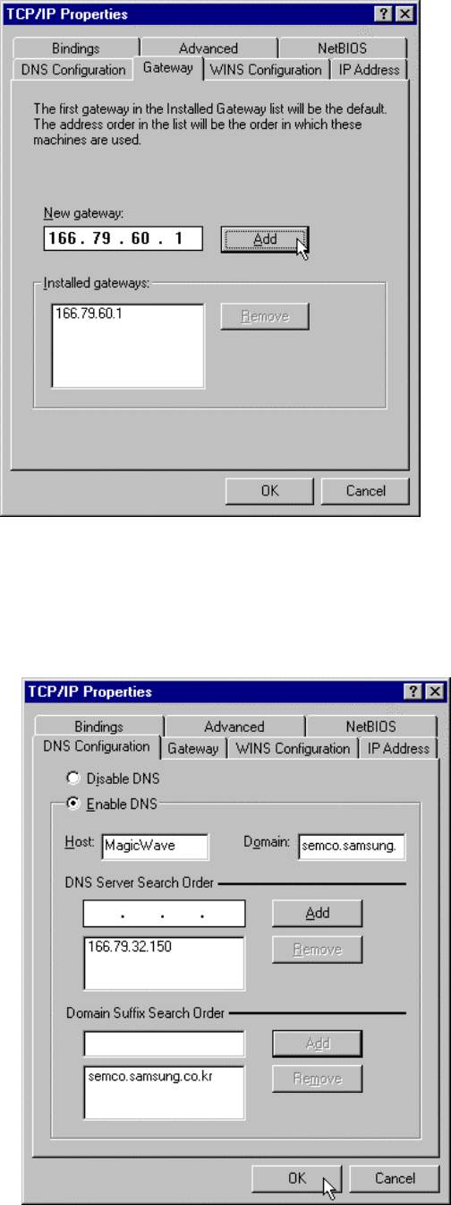
5. When you click the Configuration tab and select TCP/IP in the Network window, you might
see the TCP/IP Properties window. From here, set up your IP Address and Subnet Mask (If you
don't know this, you can find out from your network administrator).
Subnet Mask : Type the Subnet Mask number obtained from your network administrator.
This number combines with the IP address and identification, which your
computer belongs to the networks.
21
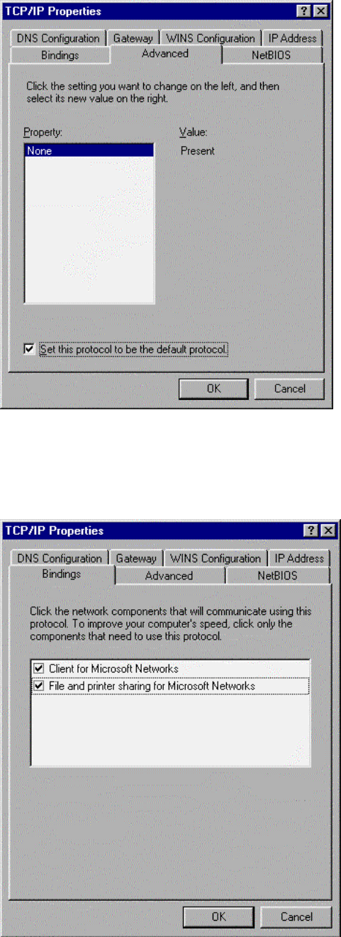
6. Click the "Gateway" tab in the TCP/IP Properties window, and then type the IP address of
gateway and click "Add" button.
7. Click the "DNS Configuration" tab, and then type IP Address of DNS server and click "Add"
button. Set up 'Host', 'Domain' and 'Domain Server Search Order' one by one, and then click
"OK" button.
22
8. Click the “Advanced” tab, and then check the "Set this protocol to be the default protocol"
and click "OK" button.
9. Click the "Bindings" tab, and confirm that "Client for Microsoft Networks" and "File and
printer sharing for Microsoft Networks" are checked. When you click "OK" button, TCP/IP
setting is completed.
23
MagicWave Adapter Card Setup
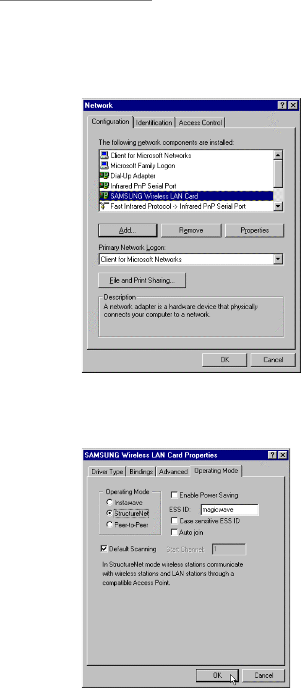
As method of Network environment setting, you can see “SAMSUNG Wireless LAN Card” at
the “Network” window in the “Control Panel”.
This component means that MagicWave adapter card (SWL-1000N or 1000D) is correctly
working. As selecting this component, you can change into the desired value.
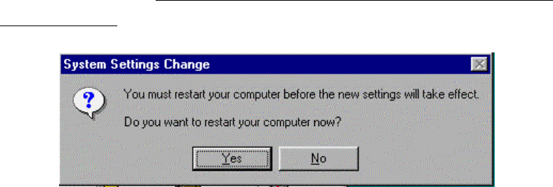
1. Click the “Properties” and then “SAMSUNG Wireless LAN Card Properties” window
appear. Click “Operating Mode” tab and type desired ESS ID.
24
- BSS (Extended Service Set ) : Minimum cell that composed wireless LAN.
- ESS (Extended Service Set ) : Interconnection of BBSs to work as one BBS.
- Instawave : In this mode wireless stations commuicate directly with each other and through
compatible access point
- StructureNet : In this mode wireless sations communicate with wireless stations and LAN
stations through a compatible Access Point
- Peer-to-Peer :In this mode wireless stations communicate directly with other wireless stations
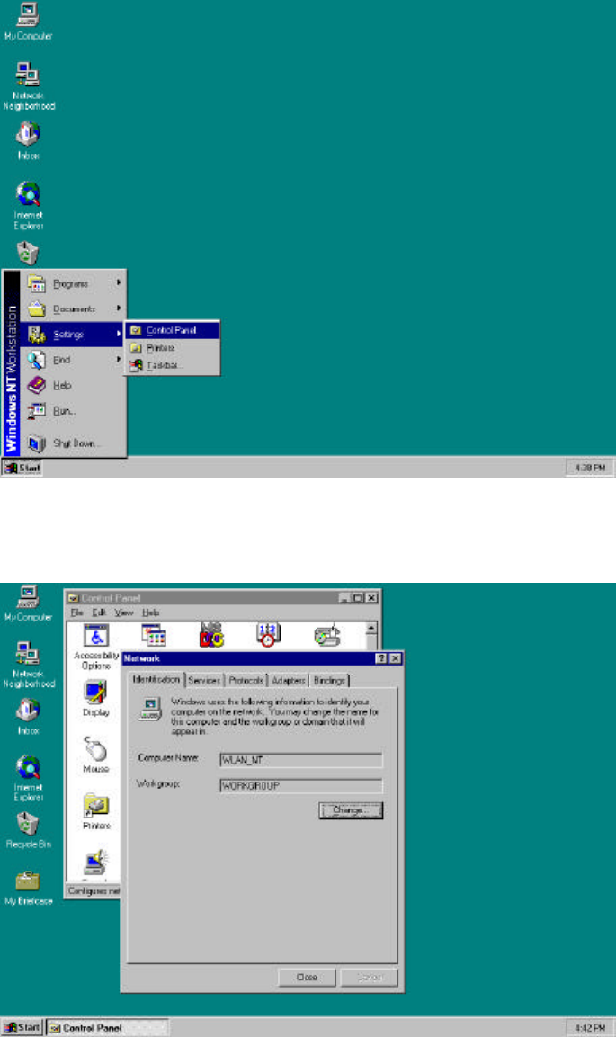
3. Set up “DTIM period” and “Fragmentation Threshold”, “Listen Interval”, “RTS Threshold”
in advanced tab if you need, and then click “OK” button. Then, you can see “Do you want to
restart your computer now?” window. Click "Yes" button and then your computer will restart to
set up your adapter card. (Recommend Cold booting, Some Desk top cannot load PNP Bios
when warm booted.)
25
Windows NT Setup
The Network setting for Windows NT is as follows;
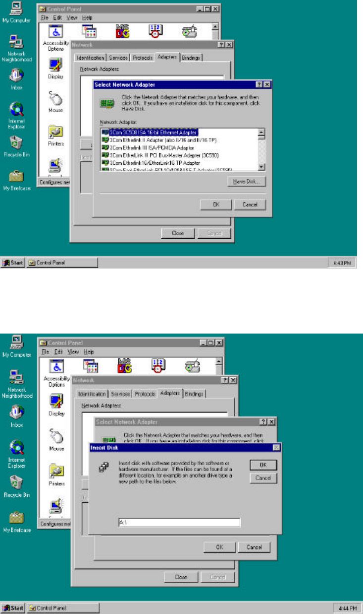
1. First, insert the MagicWave Adapter card in the empty slot, you should turn on PC.
After booting of the PC, click “Start”, ”Settings” and “Control Panel”.
2. When select the “Network” icon a network windows shown as below.
You can change the “Computer Name” and “Workgroup” after click the “Change” button.
26
3. Select “Adapter” tab, click the “Have Disk..” button as below picture.
4. Insert the provided disk “Install Diskette” and specify the path “A:\” in blank field as below
picture and click “OK”.
27
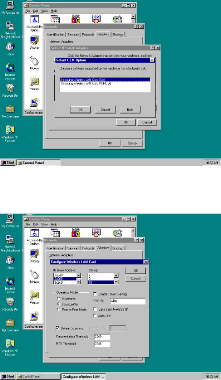
5. If the location of the DRIVER is set normally, you can see the following picture.
Select the card type (ISA or PCMCIA) and click “OK” button.
6. Set each parameter (I/O Base, IRQ Level, ESS ID...) to proper value for your computer.
Click the “OK” button if the setting is complete.
28
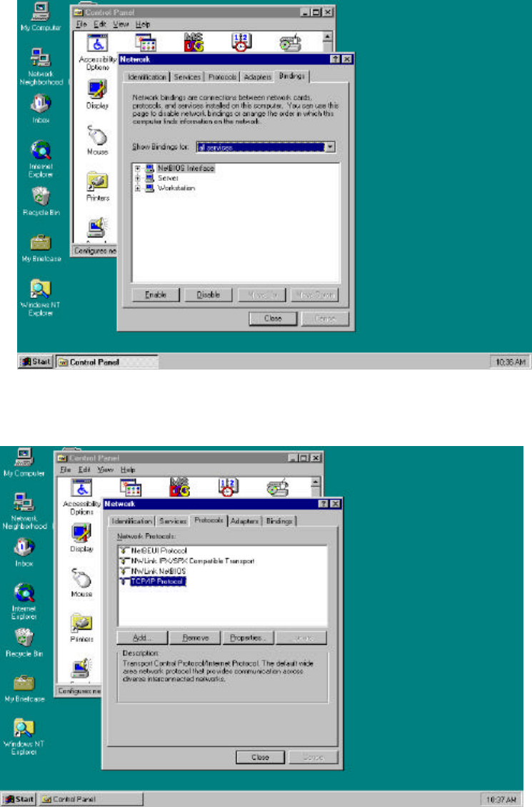
7. Select the “Bindings” and set up the items that you want.
8. Select “TCP/IP protocol” in the “Protocols” tab, and click the “Properties...”.
29
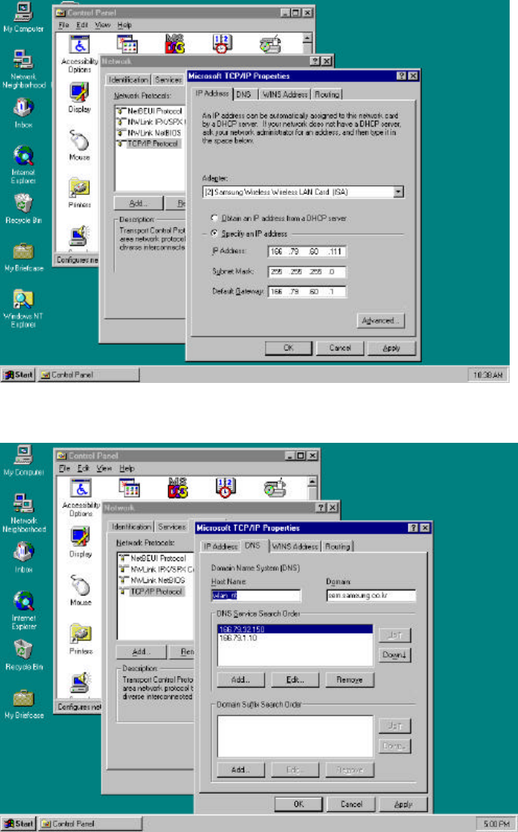
9. In the “IP Address” tab, sets up each parameter (IP Address, Subnet Mask, Default Gateway)
suitable for your environment of the network (Request from your network administrator).
10. In the “DNS” tab, set up each parameter.
30
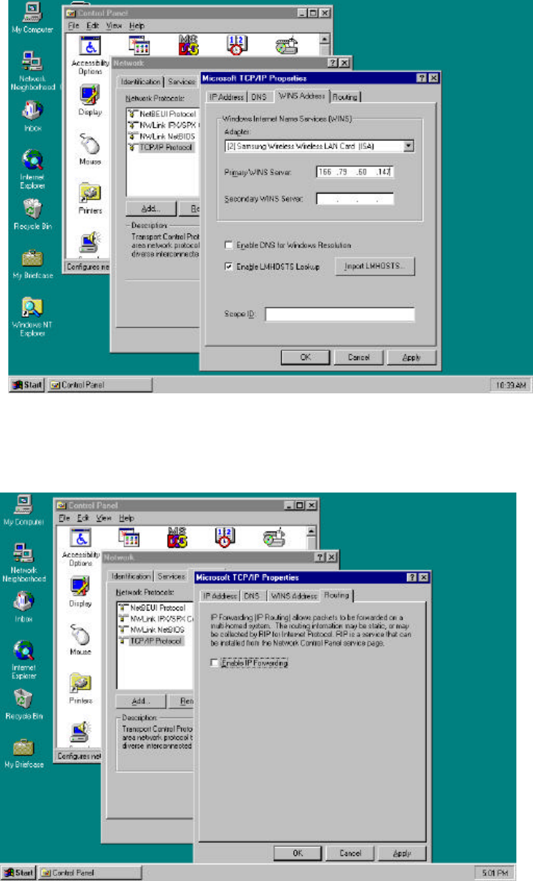
11. Select the “WINS Address” and set up each parameter.
12. After select the “Routing” checking enable use IP Forwarding or not.
Click the “OK” button, and then the setting of the TCP/IP Protocol Properties are completed.
31
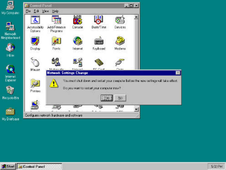
13. Click the “Close” button, appear message that “Do you want to restart your computer
now?”. If you click the “OK” button the PC is going to restart.
32
4. Access Point installation Guide and Manual
Access Point Setup
In order to connect SWL-1000AP with the established ethernet to build an infrastructure
network, you must modify the CONFIG in the Access Point using a PC and a Null Modem
Cable.
Installation can be done easily as follows;
1. Link the PC serial port and the AP serial port with Null Modem Cable, and ethernet
connection can be made either via the Coax ( 10Base 2 ) or RJ45 ( 10Base T ) connector.
2. Insert the SWL-1000AP into the PCMCIA slot of the Access Point.
3. Plug the power cord into the socket on the back of the AP.
4. All the LEDs will on and off, if the “alert” LED remains on it indicates an error condition.
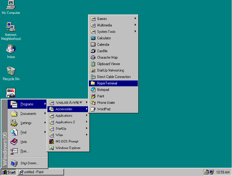
5. The sequence is as shown in the following picture, select “Start -> Programs -> Accessories
-> Hyper Terminal “
6. If there is no “HYPER TERMINAL” in the “Accessories” you must reinstall “Windows
Setup” as follows;
“ Control Panel -> Add/Remove Programs -> Windows Setup -> Communications ->
Hyperterminal”.
33
After rebooting the PC, try it again #5 status.
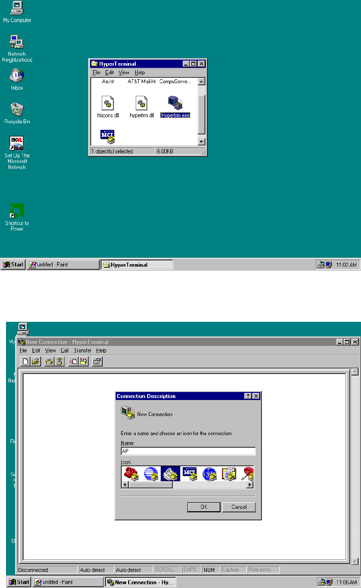
7. Double click the “Hypertrm”
8. Fill the “Name” item with the wanted Name and click “OK” button
34
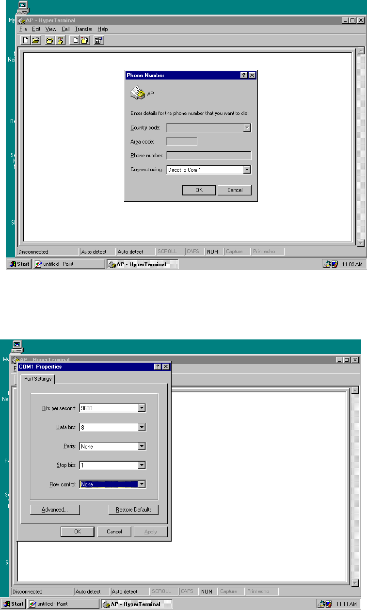
9. Select the “Direct to Com 1” at the “Connect using” item.
10. The “Port Settings” are same as the following picture Bits per second = 9600,
Data bits = 8, Parity = None, Stop bits = 1 and Flow control = None.
35
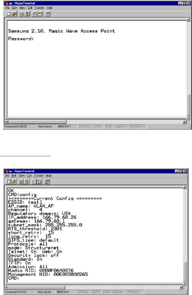
11. Click the “OK” button, you can see the next initial figure and if the connection is
performed.
There is shown “9600-8-N-1” message on the status bar.
Modify CONFIG.TXT

36
1. Password is preset to “default”.
2. In order to identify the CONFIG, you write in “config” and press the ENTER key.
3. For getting help about commander just type “help”.
4. You can modify the environment using the SET command.
As follows;
CMD: set ESSID magicwave ( Group Name )
CMD: set AP_name WLAN_AP (Access Point Name)
CMD: set channel 1 ( RF channel )
CMD: set IP_address 123.45.67.8 ( origin IP of the AP )
CMD: set gateway 123.45.67.1
CMD: set mode structurenet
CMD: set Telnet on / off ( for telnet connection )
CMD: set Web on / off ( for http connection)
CMD: set standard on (for interoperability)
5. After all the parameters are change as you want, executes “restart” command .
Null Modem Cable Configuration
9 pin female connector 9 pin female connector
pin 5 <==============> pin 5 < Ground - Ground >
pin 3 <==============> pin 2 < Transmit - Receive >
pin 7 <==============> pin 8 < RTS - CTS >
pin 6 <==============> pin 4 < DSR - DTR >
pin 2 <==============> pin 3 < Receive - Transmit >
pin 8 <==============> pin 7 < CTS - RTS >
pin 4 <==============> pin 6 < DTR - DSR >

37
Parameter Descriptions
The available parameters are described below. Some parameters can be ignored but are
assigned by default values.
u RADIO RELATED
channel : This field specifies the operating channel for the SWL-1000AP.( The SWL-1000AP
allows from 1 to 13 but the channels used by adjacent AP should be apart by more than 5
channels )
RTS_threshold : This field determines the size of RTS(Request-To-Send)/CTS(Clear-To-Send)
frames and the frames to be used.
Default : 2301
shot_retry : This field specifies the number of the transmission of RTS/CTS which will be
attempted before aborting when the communication between clients is interfered. Note that
RTS/CTS are delivered back and forth between the clients to monitor the channel for the
possibility of communications.
Default : 15
long_retry : This field specifies the number of trials of the data transmission when the channel
or a client causes the cease of data transmissions.
Default : 15
Standard : This field is used for interoperability between multiple IEEE802.11 venders.
Default : off
u ACCESS POINT FEATURES
essid : This field is used to name that wireless LAN group when in StructureNet mode. Its
value must be the same as that of clients. So if the roaming is to be supported, the value of
ESS_ID of all the AP should be the same.
Default : wlan
ap_name : This field is a string up to 9 letters and is used to give the SWL-1000AP an
identifier name. This is useful if you have multiple AP on a network for roaming. In this case
the essid for all the AP is the same but you can assign a different “ap_name” to each AP.
Default : LocalAP
38
mode : This field specifies the operating mode of the units. Insert the “Instawave” for <Ad-
hoc> and the “StructureNet” for <Infrastructure>.
Default : Instawave
protocol : The normal mode of the AP is to pass all protocols. In this case the value of default
of protocol should be “all”. If your wireless stations only use TCP/IP protocol you can set the
value of protocols to “TCP/IP”. In this case non TCP/IP messages are not passed by the AP.
u TCP/IP PARAMETERS
IP_address : This field is used to assign a TCP/IP address to the AP and needed when a user
manages the AP by TELNET or uses web manager utilities. A user can access a manage
program for the AP by putting in the assigned IP address on TELNET or WEB BROWSER.
subnet_mask : This field is used to define the TCP/IP sub-net mask. This field should be set if
you plan to use the built in management features of the AP.
Default : 255.255.255.0
gateway : This field is needed to connect to an external network by using the TCP/IP protocol.
SWL-1000AP stores all the IP addresses received from TCP/IP ARP (Address Resolution
Protocol) message. If the destination is an IP address instead of a local network,
the packets are sent to a gateway.
Default : 0.0.0.0 ( no gateway )
u MANAGEMENT FUNCTIONS
password : This field allows the manager to define the password used by the Command Line
Manager before they can enter commands.
Default : “default”
telnet : This field enables or disables the built TELNET management capability. This field will
not affect a terminal attached via the serial port, which is always enabled when a terminal is
attached. Acceptable values for the field are “on” and “off”.
Default : on
web : This field enables or disables the built in web management utility. Acceptable values for
the field are “on” and “off”.
39
Default : on
u DIAGNOSTIC METHOD
1. When the “power” LED of the Access Point is not illuminates.
* Make sure that the power cord is fully seated in the socket on the rear panel of the unit.
2. When the “alert” LED continuous illuminates or blinks.
* Check the states of the radio card ( SWL-1000N ) installed in the Access Point.
* Make sure the POWER reconnect (OFF/ON again). Operations are not incorrect
continuously, please contact your local service center or the retailer where you purchased
the units.
40
5. Management Utilities (Web, Telnet)
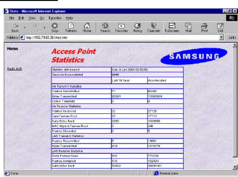
Management Utility (Main Screen = http://166.79.60.26)
In order to view the web management page, start your web browser and click on the “address”
or “URL” field, simply enter the IP address of the Access Point.
On most browsers the screen will refresh with the latest information every 10 seconds. With
IE4.0 you can stop the auto refresh by clicking on the “Stop” button of the browser.
l Time : The current time as set in the SWL-1000AP
l Access Point Name : The “AP_name” parameter of the SWL-1000AP.
l Wireless Network Status : If the radio is operating normally the field will show “Up”. If
there is a problem with the radio, or no radio installed, the field will show “Down”.
l Number Associated Wireless Stations : This shows how many wireless stations are
currently connected to the access point.
l LAN Network status : This field will show “TP” when the Twisted Pair (10baseT)
connection is operation. Otherwise it will show “Coax”.
There are several Hyperlinks on the web page. Theses act just like conventional Hyperlinks and
may take the browser to other web pages
1. Wireless/LAN: These sections provide access to the network status screens showing a
41
summary of the current active wireless and wired LAN devices.
2. Configurations: The configuration section displays the current configuration and allows
access to a screen for updating the configuration.
3. Statistics: This section of the web manager provides information and operating statistics
for access point and radio functions
Statistics Screen (Statistics Screen =http: 166.79.60.26/stats.htm)

42
The statistics screen shows accumulated traffic information. Two columns are shown: “last 10
seconds” and, “accumulated”. Traffic statistics are collected and updated every 10 seconds. The
“last 10 seconds” display shows the last 10 second collection period (the may not be precisely
the 10 seconds before the screen is refreshed). The screen will automatically update every 10
seconds
The meaning of the fields is given in the following table:
Field Name Description
Air Transmit Statistics
Frames Transmitted The count of frames transmitted on the wireless medium.
This does not count retry frames - if a frame is sent twice.
Bytes Transmitted The number of bytes contained in the frames that have been
transmitted.
Failed Transmits The number of frames which could not be transmitted.
Air Receive Statistics
Frames Received The number of frames of all types received by the Access
Point from the radio.
Data Frames Received The number of frames received from the radio which are
data frames (as opposed to management frames etc).
Data Bytes Received The number of bytes contained in the data frames received.
MAC Management Frames
Received
The number of frames received such as IEEE802.11 beacons
or association requests.
Frames Discarded The count of frames which were discarded, because of
duplicate rejection or because of buffer overflow.
LAN Transmit Statistics
Frames Transmitted The number of frames transmitted from the Access Point to
the Ethernet LAN.
Bytes Transmitted The number of bytes in the frames transmitted.
LAN Receive Statistics
Total Frame Seen The number of frames seen on the LAN
Frames Accepted The number of frames accepted by the Access Point.
Data Bytes Received The count of bytes contained in frames accepted by the AP.
Frames Discarded Frames which were discarded because of a problem. This
could be bad CRC, or buffer overflow.
43
Configuration Screen (Configuration Screen = http://166.79.60.26/config.htm)
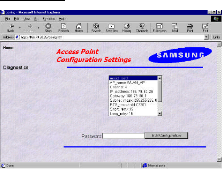
The configuration screen gives a view of the currently loaded configuration.
Type correct password and click “Edit Configuration” button, You can edit configure with
Web.
44
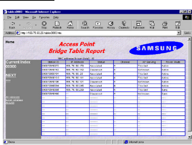
Wireless/LAN Screen (Station Screen = http://166.79.60.20/tables0000.htm)
This station screen allows the manager to see which wireless stations are currently active on the
Access Point (Wireless) and Wired LAN (LAN). The screen shows up to 18 stations at a time.
Therefore, The “NEXT” Hyperlink is causes the screen to be re-displayed showing the next 18
stations in the list and press the “PREV” Hyperlink will be shown allowing the option to go
back to the previous 18 stations in the display.
The Hyperlinks labeled as following displayed in this screen :
1. “All wireless” stations known by the Access Point including those associated with other
Access Points.
2. “Local wireless” stations which are associated with this access point.
3. “All LAN” stations which have been seen on the Ethernet LAN.

45
Field Name Description
Station ID This is the NID (Network ID) or the name of the station if
set. The name is obtained from the NID name table.
IP Address The IP address of the station ( if known )
“Associated” means that the station is associated with this
Access Point.
“Disconnected” means that the station is not associated
with this AP could however, be associated with another AP.
“Detected” means that frames from the station have been
seen but, that it has not been associated.
“Bridged” entries are wired stations that are reached
through a different Access Point than the current displayed
one.
“Is Bridging” are Access Points detected over the air. These
other Access Points provide for wireless bridging between
two separate LAN segments.
Status
“Local AP” means that it is another AP on the same LAN.
This entry will be seen where roaming is implemented.
Channel The radio channel of the station.
AP Serving If the station is associated the words “This Unit” will
appear.
Otherwise the NID or name of the Access Point to which
the station is associated will be shown.
Power Mode If the station supports “Power Save Poll” mode of
IEEE802.11, this field will indicate that power saving is
active with the word “On”.
As for the other screens it is necessary to click “refresh” or “reload” to get updated information.
46
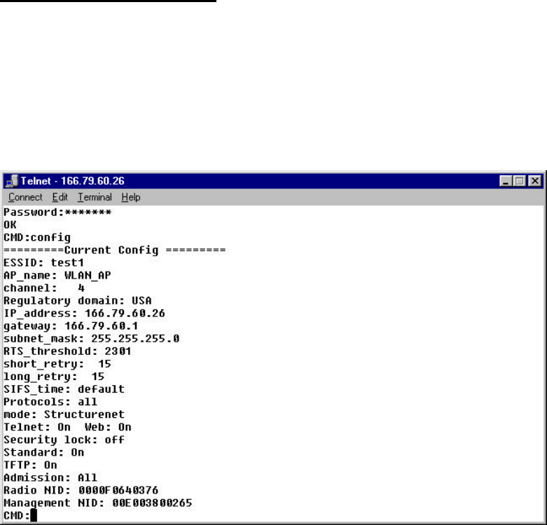
TELNET Command Manager
The SWL-1000AP provides a “telnet” terminal session to the IP address of the Access Point.
Typing the command “telnet 166.79.60.26” in the DOS windows, and the TELNET utility is
launched as below figure.
The IP address is the address of the destination Access Point.
The password is “default”.
The user may enter commands in the general format:
Command parameter1 parameter2 …
The available commands for the command line monitor are:
Help Bridge Traceon Traceoff
Trace Tracelp Traceclr Config
Ping Stats Time Settime
Setdate version Set nid
Logout Restart
47
--List of frequently used commands
u Help Command
A summary of commands can be obtained by typing the command “help”.
u Show Command
The “show” command allows inspection of the bridge table in the Access Point.
This displays information similar to the “stations” screen of the web interface.
1. “Show G” ; list of all known computers which are attached via the LAN port.
2. “Bridge S” ; list of all wireless stations.
3. “Show A” ; list of all devices via the radio link.
The result of the command is list providing the following information.
l Net ID : IEEE network address of the device.
l State : Current relationship of device with AP ( Associated, Disconnected,
Detected, is bridging, bridged, Local AP, Unknown ).
l Channel : Radio channel.
l Current AP : The Access Point with which the unit is associated.
l IP address : IP address of the device.
u System Commands
l Time Print current data and time of last re-initialization.
l Settime Set the system time.
Format is “settime HH(hours):MM(minutes):SS(seconds)”.
l Setdate Set the system date.
Format is “setdate MM(month):DD(date):YY(year)”.
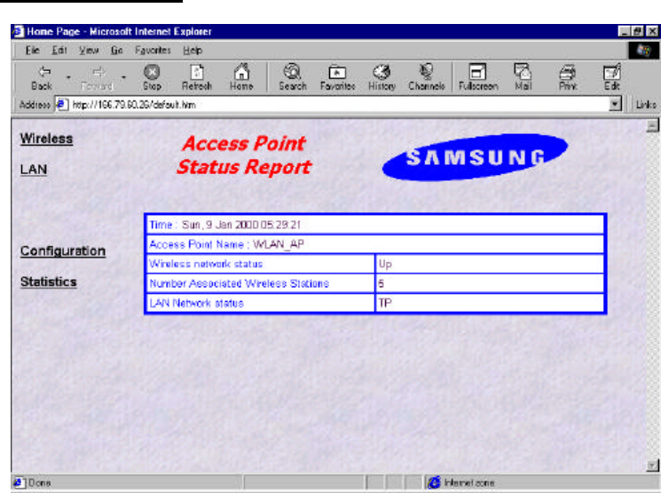
l Config Displays the current system settings for configuration. Note that if a
configuration change has been made which requires a system restart
to take effect, both the old and the new values will be shown.
l Stats The Stats command prints traffic statistics. Statistics are displayed for the
last 10 second interval and cumulative since last cleared.
The cumulative total can be cleared by the command “stats c”.
l Logout After this command has been issued the user must re-enter the password
48
before any more commands can be issued.
l Version This command prints version information about the Access Point software.
l Restart This command causes the SWL-1000AP to perform a reinitialization.
u Ping Command
l Ping The ping command causes the Access Point to issue an ICMP Echo
request
(PING) to the specified IP address.
The format of the command is : “ping 123.45.67.89”.
Where 123.45.67.89 is the destination IP address.
49
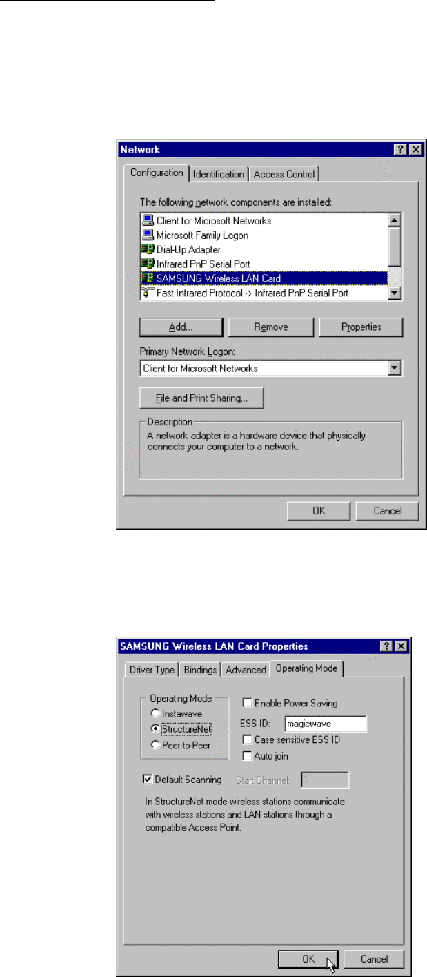
MagicWave Adapter Card Setup
As method of Network environment setting, you can see “SAMSUNG Wireless LAN Card” at
the “Network” window in the “Control Panel”.
This component means that MagicWave adapter card (SWL-1000N or 1000D) is correctly
working. As selecting this component, you can change into the desired value.
1. Click the “Properties” and then “SAMSUNG Wireless LAN Card Properties” window
appear. Click “Operating Mode” tab and type desired ESS ID.
50
- BSS (Extended Service Set ) : Minimum cell that composed wireless LAN.
- ESS (Extended Service Set ) : Interconnection of BBSs to work as one BBS.
- Instawave : In this mode wireless stations commuicate directly with each other and through
compatible access point
- StructureNet : In this mode wireless sations communicate with wireless stations and LAN
stations through a compatible Access Point
- Peer-to-Peer :In this mode wireless stations communicate directly with other wireless stations
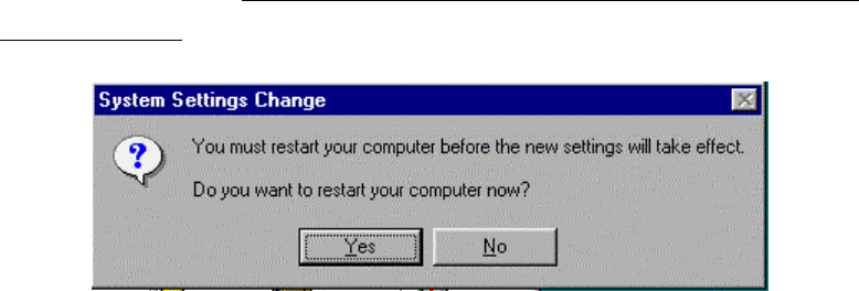
3. Set up “DTIM period” and “Fragmentation Threshold”, “Listen Interval”, “RTS Threshold”
in advanced tab if you need, and then click “OK” button. Then, you can see “Do you want to
restart your computer now?” window. Click "Yes" button and then your computer will restart to
set up your adapter card. (Recommend Cold booting, Some Desk top cannot load PNP Bios
when warm booted.)
51
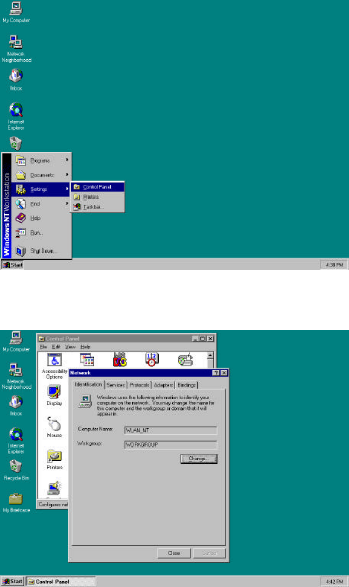
Windows NT Setup
The Network setting for Windows NT is as follows;
1. First, insert the MagicWave Adapter card in the empty slot, you should turn on PC.
After booting of the PC, click “Start”, ”Settings” and “Control Panel”.
2. When select the “Network” icon a network windows shown as below.
You can change the “Computer Name” and “Workgroup” after click the “Change” button.
52
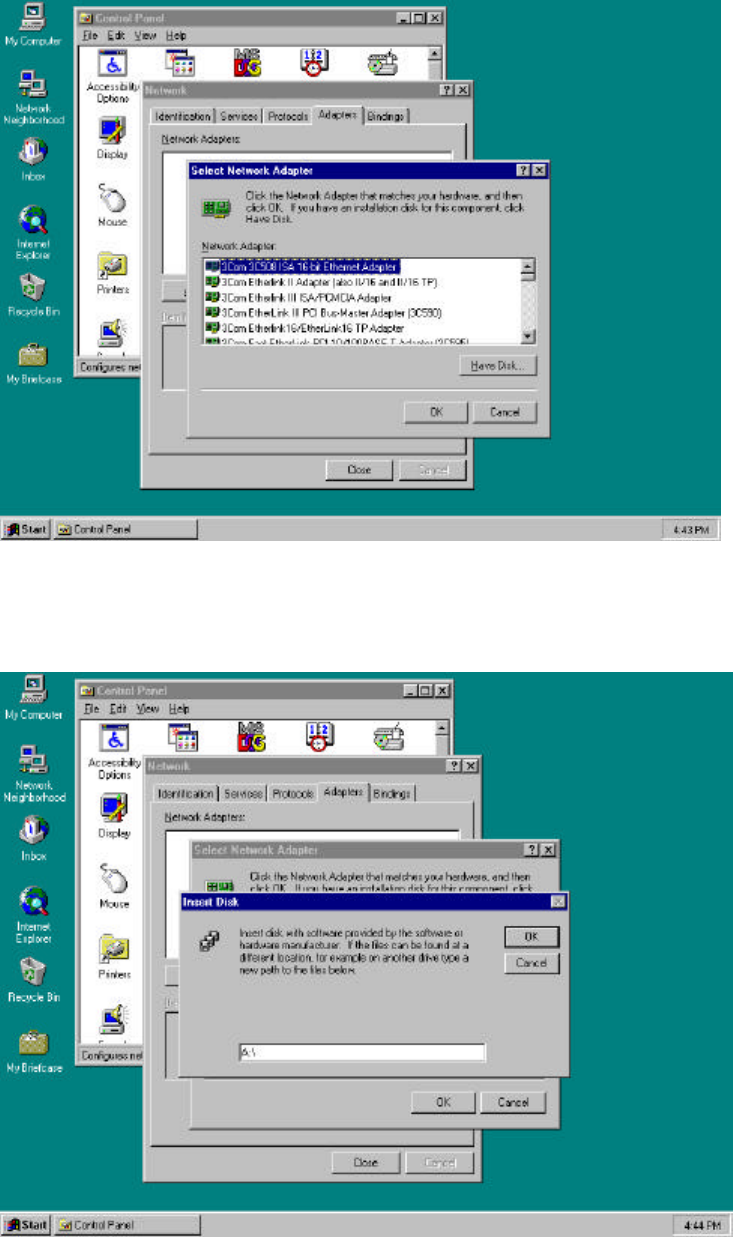
3. Select “Adapter” tab, click the “Have Disk..” button as below picture.
4. Insert the provided disk “Install Diskette” and specify the path “A:\” in blank field as below
picture and click “OK”.
53
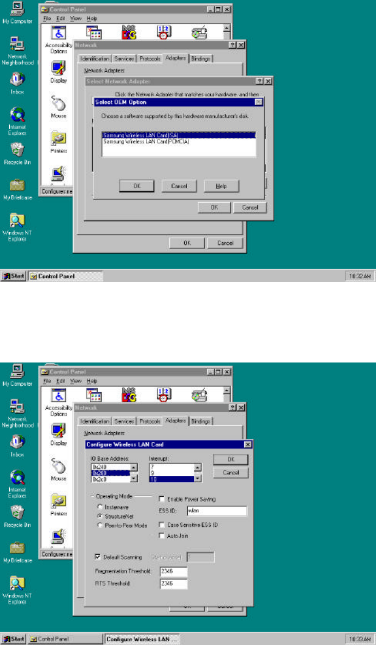
5. If the location of the DRIVER is set normally, you can see the following picture.
Select the card type (ISA or PCMCIA) and click “OK” button.
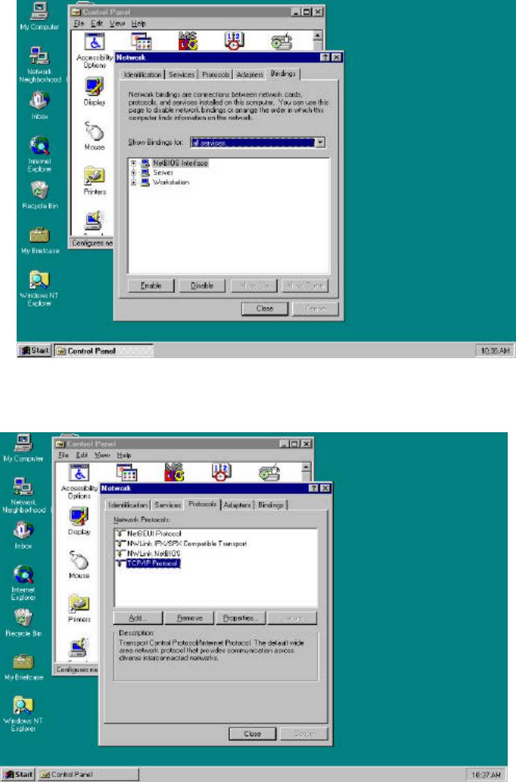
6. Set each parameter (I/O Base, IRQ Level, ESS ID...) to proper value for your computer.
Click the “OK” button if the setting is complete.
54
7. Select the “Bindings” and set up the items that you want.
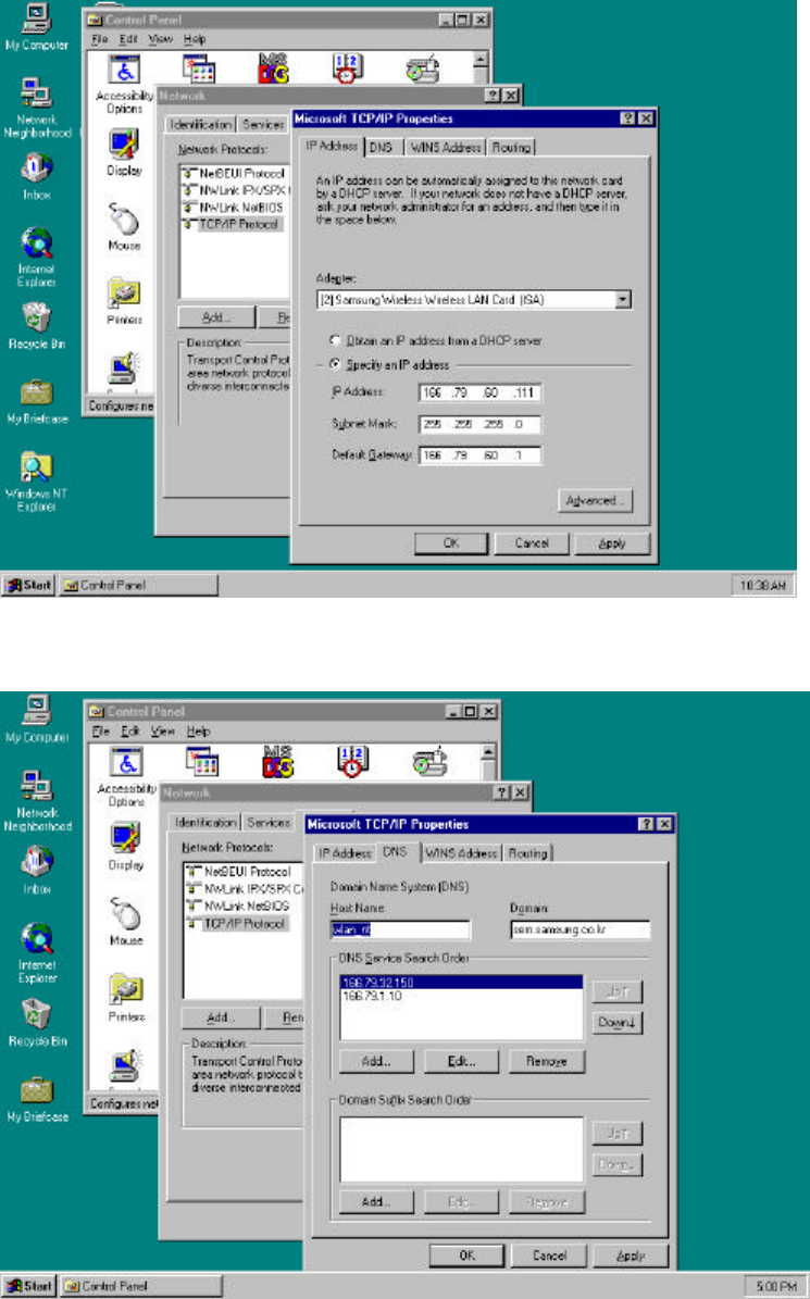
8. Select “TCP/IP protocol” in the “Protocols” tab, and click the “Properties...”.
55
9. In the “IP Address” tab, sets up each parameter (IP Address, Subnet Mask, Default Gateway)
suitable for your environment of the network (Request from your network administrator).
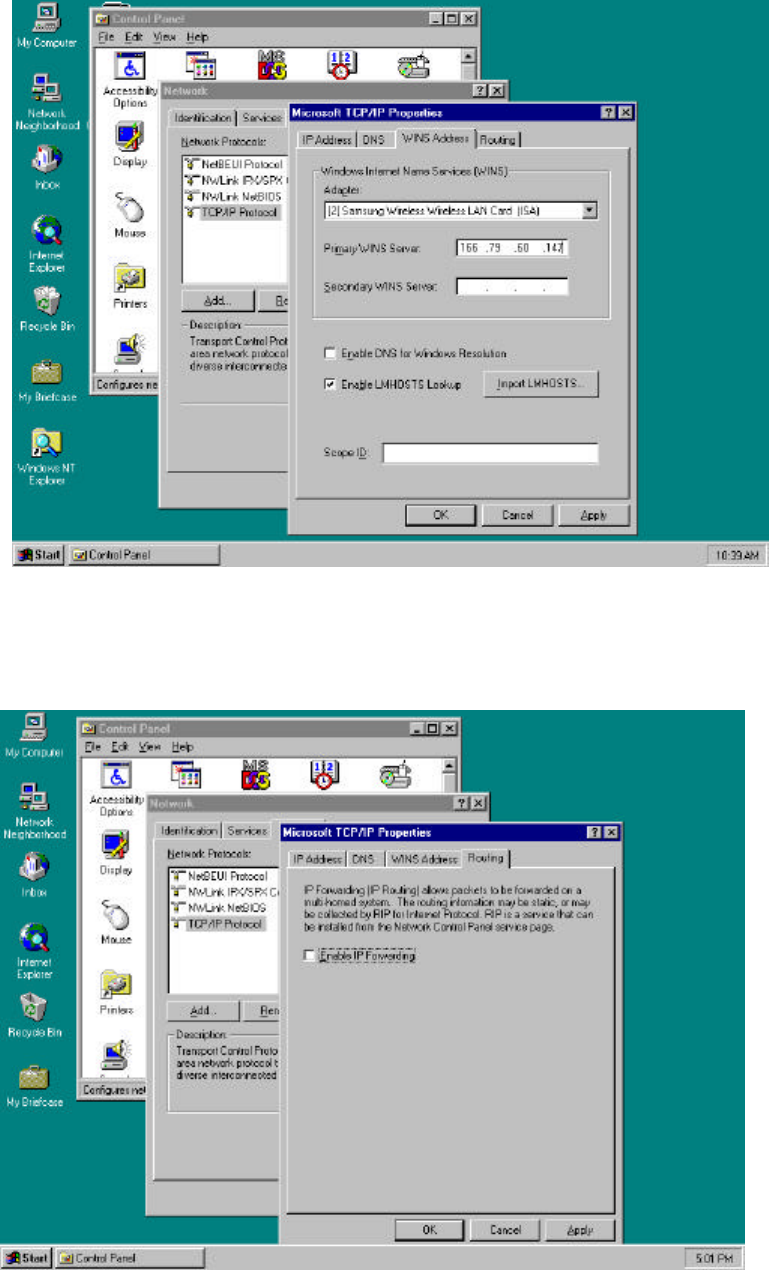
10. In the “DNS” tab, set up each parameter.
56
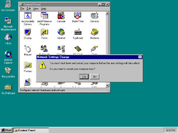
11. Select the “WINS Address” and set up each parameter.
12. After select the “Routing” checking enable use IP Forwarding or not.
Click the “OK” button, and then the setting of the TCP/IP Protocol Properties are completed.
57
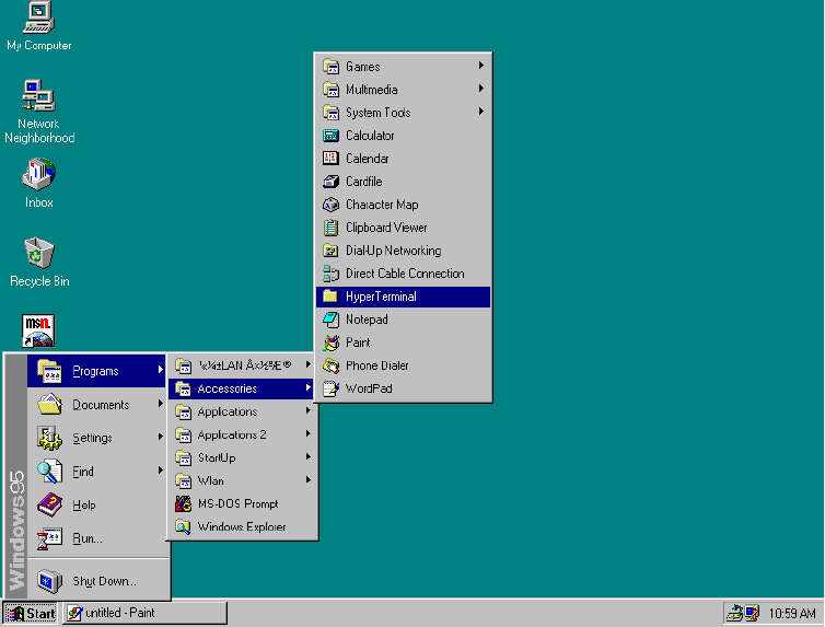
13. Click the “Close” button, appear message that “Do you want to restart your computer
now?”. If you click the “OK” button the PC is going to restart.
58
4. Access Point installation Guide and Manual
Access Point Setup
In order to connect SWL-1000AP with the established ethernet to build an infrastructure
network, you must modify the CONFIG in the Access Point using a PC and a Null Modem
Cable.
Installation can be done easily as follows;
1. Link the PC serial port and the AP serial port with Null Modem Cable, and ethernet
connection can be made either via the Coax ( 10Base 2 ) or RJ45 ( 10Base T ) connector.
2. Insert the SWL-1000AP into the PCMCIA slot of the Access Point.
3. Plug the power cord into the socket on the back of the AP.
4. All the LEDs will on and off, if the “alert” LED remains on it indicates an error condition.
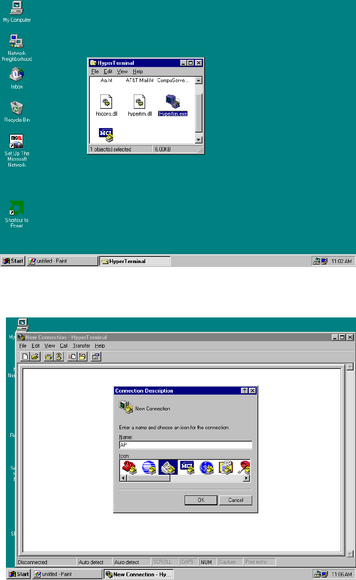
5. The sequence is as shown in the following picture, select “Start -> Programs -> Accessories
-> Hyper Terminal “
6. If there is no “HYPER TERMINAL” in the “Accessories” you must reinstall “Windows
Setup” as follows;
“ Control Panel -> Add/Remove Programs -> Windows Setup -> Communications ->
Hyperterminal”.
59
After rebooting the PC, try it again #5 status.
7. Double click the “Hypertrm”
8. Fill the “Name” item with the wanted Name and click “OK” button
60
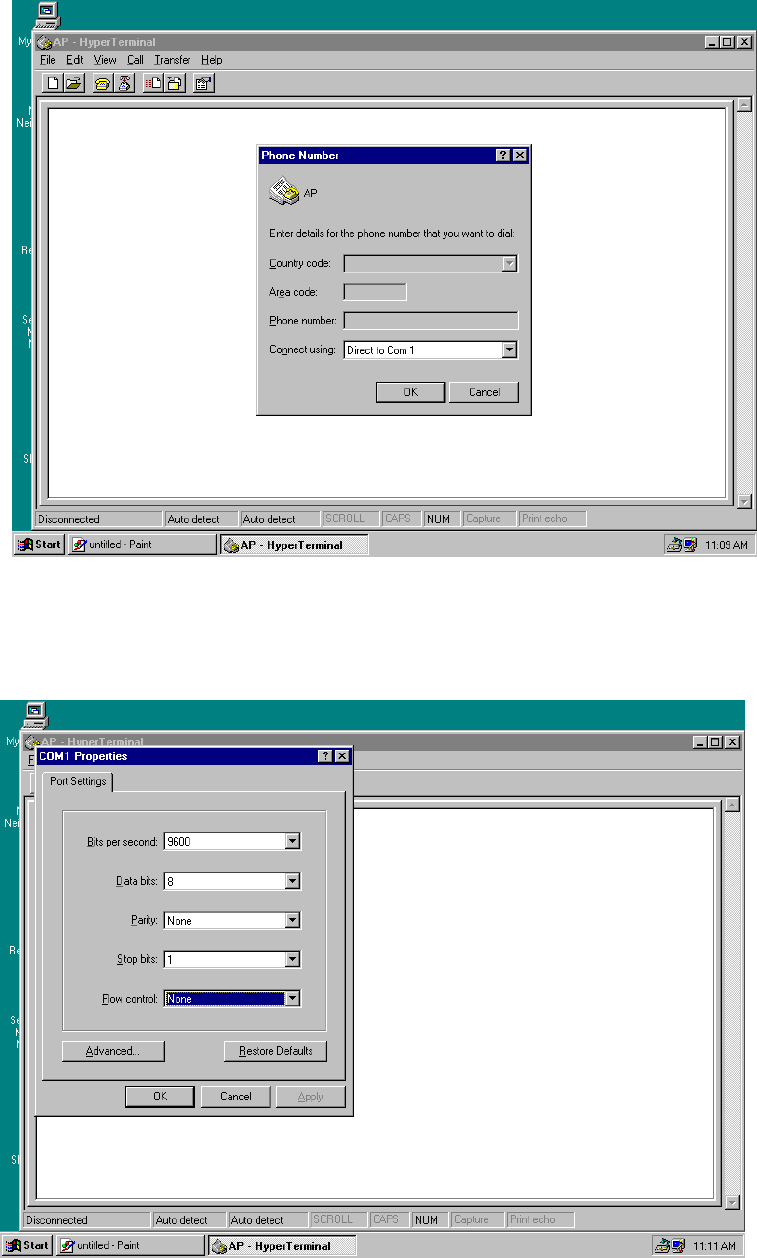
9. Select the “Direct to Com 1” at the “Connect using” item.
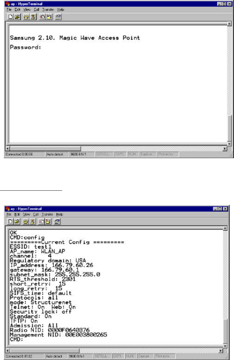
10. The “Port Settings” are same as the following picture Bits per second = 9600,
Data bits = 8, Parity = None, Stop bits = 1 and Flow control = None.
61
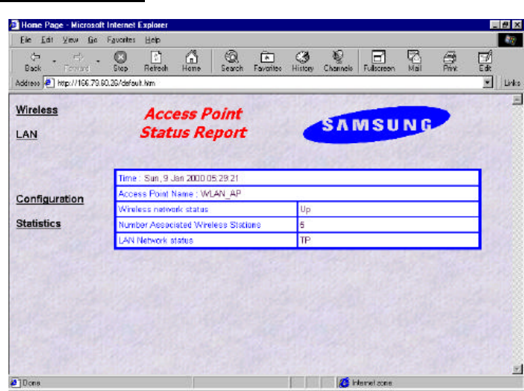
11. Click the “OK” button, you can see the next initial figure and if the connection is
performed.
There is shown “9600-8-N-1” message on the status bar.
Modify CONFIG.TXT

62
1. Password is preset to “default”.
2. In order to identify the CONFIG, you write in “config” and press the ENTER key.
3. For getting help about commander just type “help”.
4. You can modify the environment using the SET command.
As follows;
CMD: set ESSID magicwave ( Group Name )
CMD: set AP_name WLAN_AP (Access Point Name)
CMD: set channel 1 ( RF channel )
CMD: set IP_address 123.45.67.8 ( origin IP of the AP )
CMD: set gateway 123.45.67.1
CMD: set mode structurenet
CMD: set Telnet on / off ( for telnet connection )
CMD: set Web on / off ( for http connection)
CMD: set standard on (for interoperability)
5. After all the parameters are change as you want, executes “restart” command .
Null Modem Cable Configuration
9 pin female connector 9 pin female connector
pin 5 <==============> pin 5 < Ground - Ground >
pin 3 <==============> pin 2 < Transmit - Receive >
pin 7 <==============> pin 8 < RTS - CTS >
pin 6 <==============> pin 4 < DSR - DTR >
pin 2 <==============> pin 3 < Receive - Transmit >
pin 8 <==============> pin 7 < CTS - RTS >
pin 4 <==============> pin 6 < DTR - DSR >

63
Parameter Descriptions
The available parameters are described below. Some parameters can be ignored but are
assigned by default values.
u RADIO RELATED
channel : This field specifies the operating channel for the SWL-1000AP.( The SWL-1000AP
allows from 1 to 13 but the channels used by adjacent AP should be apart by more than 5
channels )
RTS_threshold : This field determines the size of RTS(Request-To-Send)/CTS(Clear-To-Send)
frames and the frames to be used.
Default : 2301
shot_retry : This field specifies the number of the transmission of RTS/CTS which will be
attempted before aborting when the communication between clients is interfered. Note that
RTS/CTS are delivered back and forth between the clients to monitor the channel for the
possibility of communications.
Default : 15
long_retry : This field specifies the number of trials of the data transmission when the channel
or a client causes the cease of data transmissions.
Default : 15
Standard : This field is used for interoperability between multiple IEEE802.11 venders.
Default : off
u ACCESS POINT FEATURES
essid : This field is used to name that wireless LAN group when in StructureNet mode. Its
value must be the same as that of clients. So if the roaming is to be supported, the value of
ESS_ID of all the AP should be the same.
Default : wlan
ap_name : This field is a string up to 9 letters and is used to give the SWL-1000AP an
identifier name. This is useful if you have multiple AP on a network for roaming. In this case
the essid for all the AP is the same but you can assign a different “ap_name” to each AP.
Default : LocalAP
64
mode : This field specifies the operating mode of the units. Insert the “Instawave” for <Ad-
hoc> and the “StructureNet” for <Infrastructure>.
Default : Instawave
protocol : The normal mode of the AP is to pass all protocols. In this case the value of default
of protocol should be “all”. If your wireless stations only use TCP/IP protocol you can set the
value of protocols to “TCP/IP”. In this case non TCP/IP messages are not passed by the AP.
u TCP/IP PARAMETERS
IP_address : This field is used to assign a TCP/IP address to the AP and needed when a user
manages the AP by TELNET or uses web manager utilities. A user can access a manage
program for the AP by putting in the assigned IP address on TELNET or WEB BROWSER.
subnet_mask : This field is used to define the TCP/IP sub-net mask. This field should be set if
you plan to use the built in management features of the AP.
Default : 255.255.255.0
gateway : This field is needed to connect to an external network by using the TCP/IP protocol.
SWL-1000AP stores all the IP addresses received from TCP/IP ARP (Address Resolution
Protocol) message. If the destination is an IP address instead of a local network,
the packets are sent to a gateway.
Default : 0.0.0.0 ( no gateway )
u MANAGEMENT FUNCTIONS
password : This field allows the manager to define the password used by the Command Line
Manager before they can enter commands.
Default : “default”
telnet : This field enables or disables the built TELNET management capability. This field will
not affect a terminal attached via the serial port, which is always enabled when a terminal is
attached. Acceptable values for the field are “on” and “off”.
Default : on
web : This field enables or disables the built in web management utility. Acceptable values for
the field are “on” and “off”.
65
Default : on
u DIAGNOSTIC METHOD
3. When the “power” LED of the Access Point is not illuminates.
* Make sure that the power cord is fully seated in the socket on the rear panel of the unit.
4. When the “alert” LED continuous illuminates or blinks.
* Check the states of the radio card ( SWL-1000N ) installed in the Access Point.
* Make sure the POWER reconnect (OFF/ON again). Operations are not incorrect
continuously, please contact your local service center or the retailer where you purchased
the units.
66
5. Management Utilities (Web, Telnet)
Management Utility (Main Screen = http://166.79.60.26)
In order to view the web management page, start your web browser and click on the “address”
or “URL” field, simply enter the IP address of the Access Point.
On most browsers the screen will refresh with the latest information every 10 seconds. With
IE4.0 you can stop the auto refresh by clicking on the “Stop” button of the browser.
l Time : The current time as set in the SWL-1000AP
l Access Point Name : The “AP_name” parameter of the SWL-1000AP.
l Wireless Network Status : If the radio is operating normally the field will show “Up”. If
there is a problem with the radio, or no radio installed, the field will show “Down”.
l Number Associated Wireless Stations : This shows how many wireless stations are
currently connected to the access point.
l LAN Network status : This field will show “TP” when the Twisted Pair (10baseT)
connection is operation. Otherwise it will show “Coax”.
There are several Hyperlinks on the web page. Theses act just like conventional Hyperlinks and
may take the browser to other web pages
4. Wireless/LAN: These sections provide access to the network status screens showing a
67
summary of the current active wireless and wired LAN devices.
5. Configurations: The configuration section displays the current configuration and allows
access to a screen for updating the configuration.
6. Statistics: This section of the web manager provides information and operating statistics
for access point and radio functions
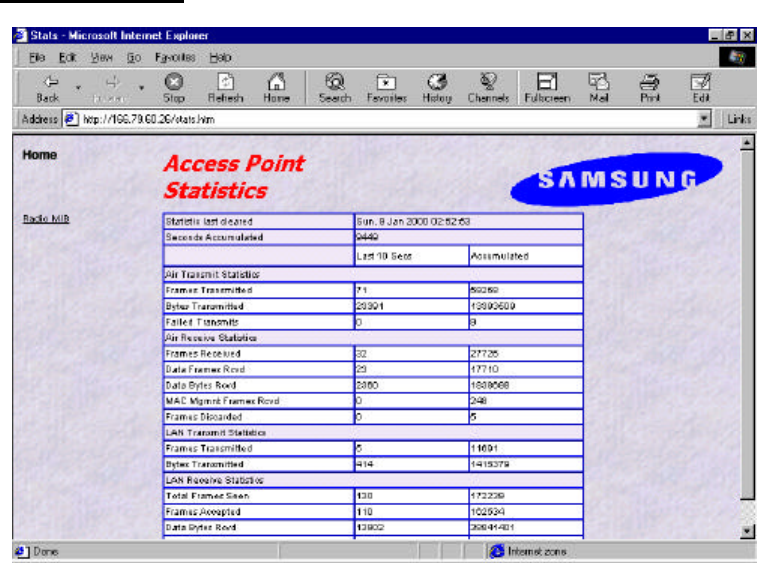
Statistics Screen (Statistics Screen =http: 166.79.60.26/stats.htm)

68
The statistics screen shows accumulated traffic information. Two columns are shown: “last 10
seconds” and, “accumulated”. Traffic statistics are collected and updated every 10 seconds. The
“last 10 seconds” display shows the last 10 second collection period (the may not be precisely
the 10 seconds before the screen is refreshed). The screen will automatically update every 10
seconds
The meaning of the fields is given in the following table:
Field Name Description
Air Transmit Statistics
Frames Transmitted The count of frames transmitted on the wireless medium.
This does not count retry frames - if a frame is sent twice.
Bytes Transmitted The number of bytes contained in the frames that have been
transmitted.
Failed Transmits The number of frames which could not be transmitted.
Air Receive Statistics
Frames Received The number of frames of all types received by the Access
Point from the radio.
Data Frames Received The number of frames received from the radio which are
data frames (as opposed to management frames etc).
Data Bytes Received The number of bytes contained in the data frames received.
MAC Management Frames
Received
The number of frames received such as IEEE802.11 beacons
or association requests.
Frames Discarded The count of frames which were discarded, because of
duplicate rejection or because of buffer overflow.
LAN Transmit Statistics
Frames Transmitted The number of frames transmitted from the Access Point to
the Ethernet LAN.
Bytes Transmitted The number of bytes in the frames transmitted.
LAN Receive Statistics
Total Frame Seen The number of frames seen on the LAN
Frames Accepted The number of frames accepted by the Access Point.
Data Bytes Received The count of bytes contained in frames accepted by the AP.
Frames Discarded Frames which were discarded because of a problem. This
could be bad CRC, or buffer overflow.
69
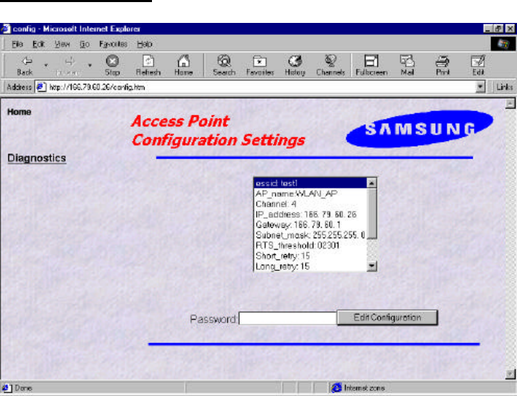
Configuration Screen (Configuration Screen = http://166.79.60.26/config.htm)
The configuration screen gives a view of the currently loaded configuration.
Type correct password and click “Edit Configuration” button, You can edit configure with
Web.
70
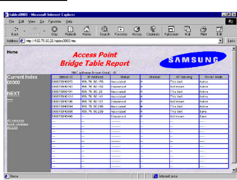
Wireless/LAN Screen (Station Screen = http://166.79.60.20/tables0000.htm)
This station screen allows the manager to see which wireless stations are currently active on the
Access Point (Wireless) and Wired LAN (LAN). The screen shows up to 18 stations at a time.
Therefore, The “NEXT” Hyperlink is causes the screen to be re-displayed showing the next 18
stations in the list and press the “PREV” Hyperlink will be shown allowing the option to go
back to the previous 18 stations in the display.
The Hyperlinks labeled as following displayed in this screen :
4. “All wireless” stations known by the Access Point including those associated with other
Access Points.
5. “Local wireless” stations which are associated with this access point.
6. “All LAN” stations which have been seen on the Ethernet LAN.

71
Field Name Description
Station ID This is the NID (Network ID) or the name of the station if
set. The name is obtained from the NID name table.
IP Address The IP address of the station ( if known )
“Associated” means that the station is associated with this
Access Point.
“Disconnected” means that the station is not associated
with this AP could however, be associated with another AP.
“Detected” means that frames from the station have been
seen but, that it has not been associated.
“Bridged” entries are wired stations that are reached
through a different Access Point than the current displayed
one.
“Is Bridging” are Access Points detected over the air. These
other Access Points provide for wireless bridging between
two separate LAN segments.
Status
“Local AP” means that it is another AP on the same LAN.
This entry will be seen where roaming is implemented.
Channel The radio channel of the station.
AP Serving If the station is associated the words “This Unit” will
appear.
Otherwise the NID or name of the Access Point to which
the station is associated will be shown.
Power Mode If the station supports “Power Save Poll” mode of
IEEE802.11, this field will indicate that power saving is
active with the word “On”.
As for the other screens it is necessary to click “refresh” or “reload” to get updated information.
72
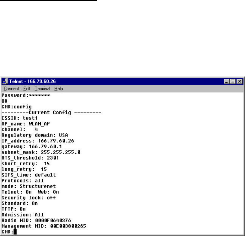
TELNET Command Manager
The SWL-1000AP provides a “telnet” terminal session to the IP address of the Access Point.
Typing the command “telnet 166.79.60.26” in the DOS windows, and the TELNET utility is
launched as below figure.
The IP address is the address of the destination Access Point.
The password is “default”.
The user may enter commands in the general format:
Command parameter1 parameter2 …
The available commands for the command line monitor are:
Help Bridge Traceon Traceoff
Trace Tracelp Traceclr Config
Ping Stats Time Settime
Setdate version Set nid
Logout Restart
73
--List of frequently used commands
u Help Command
A summary of commands can be obtained by typing the command “help”.
u Show Command
The “show” command allows inspection of the bridge table in the Access Point.
This displays information similar to the “stations” screen of the web interface.
4. “Show G” ; list of all known computers which are attached via the LAN port.
5. “Bridge S” ; list of all wireless stations.
6. “Show A” ; list of all devices via the radio link.
The result of the command is list providing the following information.
l Net ID : IEEE network address of the device.
l State : Current relationship of device with AP ( Associated, Disconnected,
Detected, is bridging, bridged, Local AP, Unknown ).
l Channel : Radio channel.
l Current AP : The Access Point with which the unit is associated.
l IP address : IP address of the device.
u System Commands
l Time Print current data and time of last re-initialization.
l Settime Set the system time.
Format is “settime HH(hours):MM(minutes):SS(seconds)”.
l Setdate Set the system date.
Format is “setdate MM(month):DD(date):YY(year)”.
l Config Displays the current system settings for configuration. Note that if a
configuration change has been made which requires a system restart
to take effect, both the old and the new values will be shown.
l Stats The Stats command prints traffic statistics. Statistics are displayed for the
last 10 second interval and cumulative since last cleared.
The cumulative total can be cleared by the command “stats c”.
l Logout After this command has been issued the user must re-enter the password
74
before any more commands can be issued.
l Version This command prints version information about the Access Point software.
l Restart This command causes the SWL-1000AP to perform a reinitialization.
u Ping Command
l Ping The ping command causes the Access Point to issue an ICMP Echo
request
(PING) to the specified IP address.
The format of the command is : “ping 123.45.67.89”.
Where 123.45.67.89 is the destination IP address.