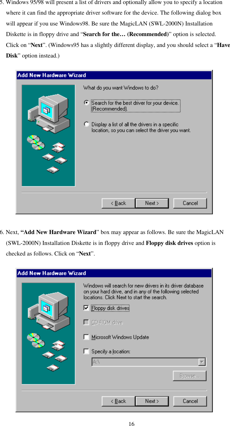
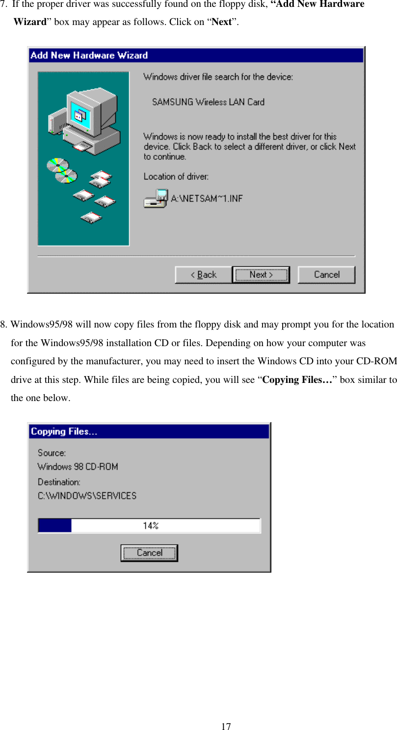
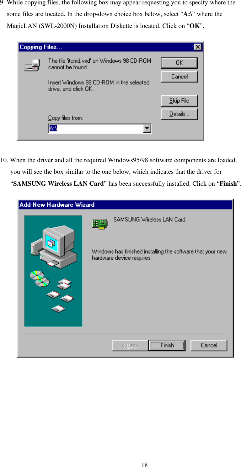
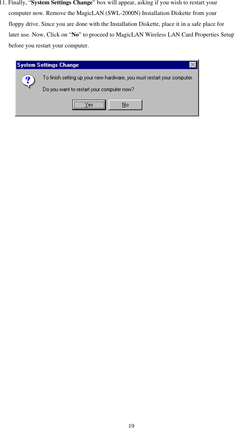
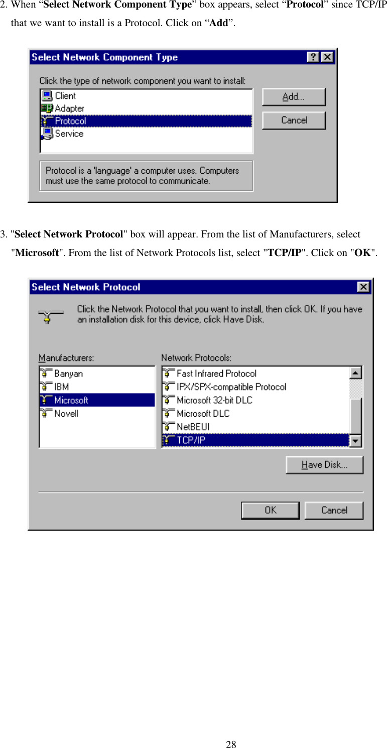
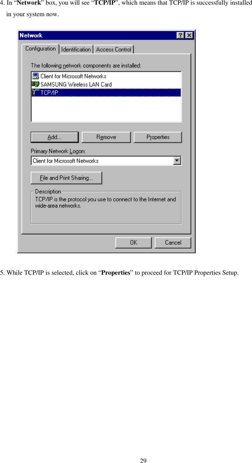
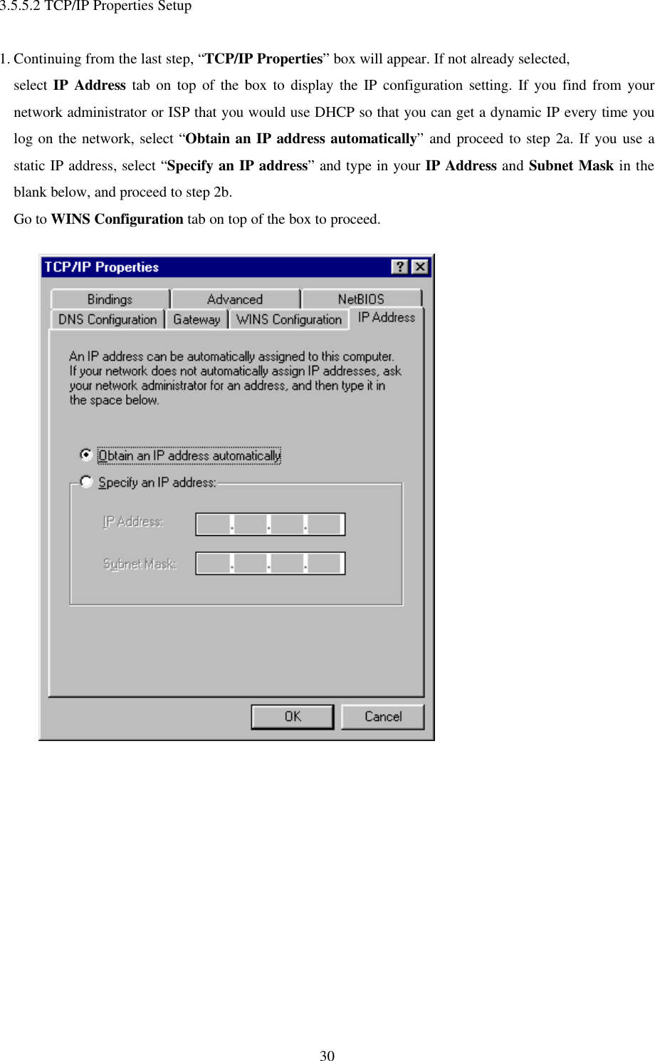
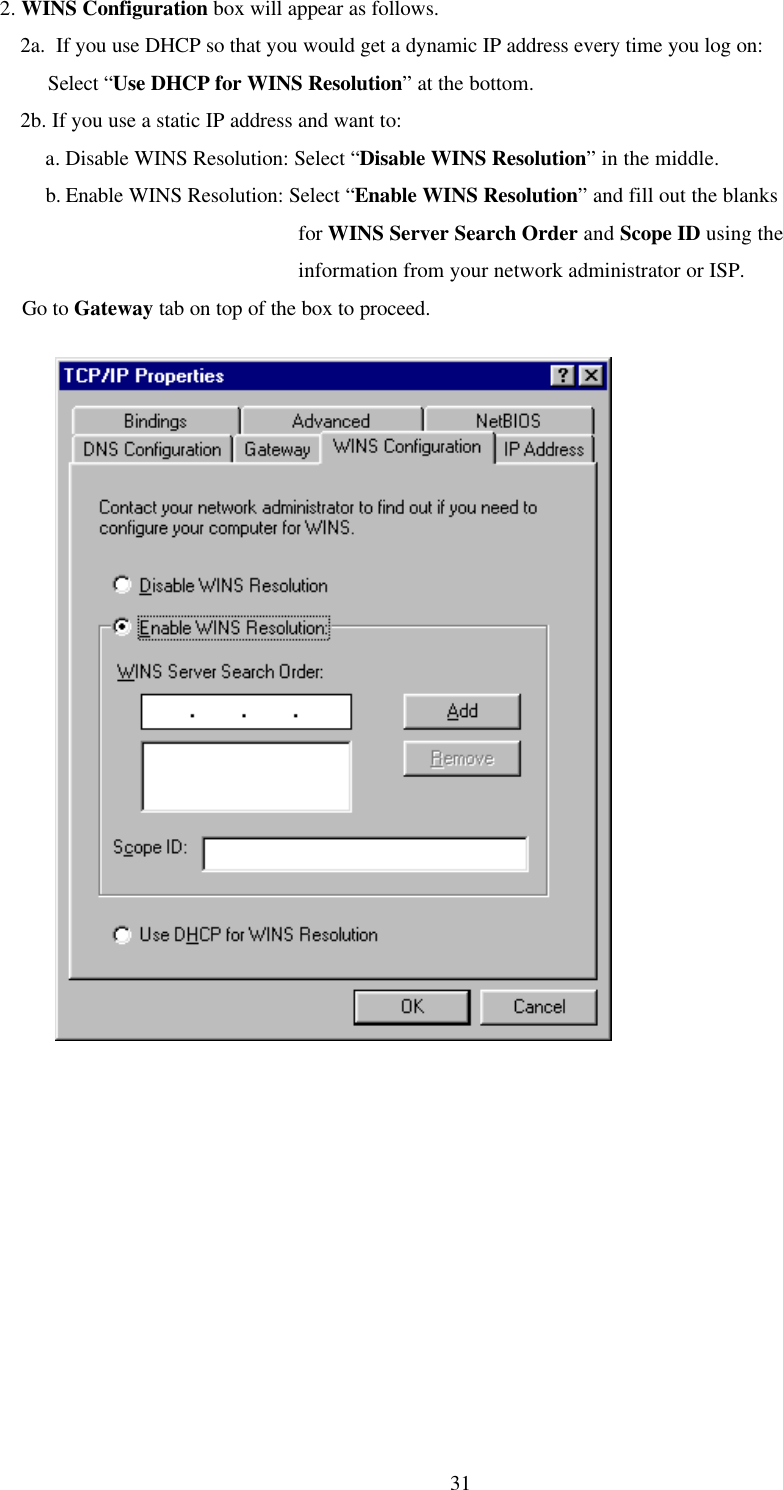
Samsung Electro Mechanics SWL-2000N User Manual Manual
Samsung Electro Mechanics Manual
UserManual.wiki
>
Samsung Electro Mechanics
>
SWL-2000N User Manual
>
Manual
Contents
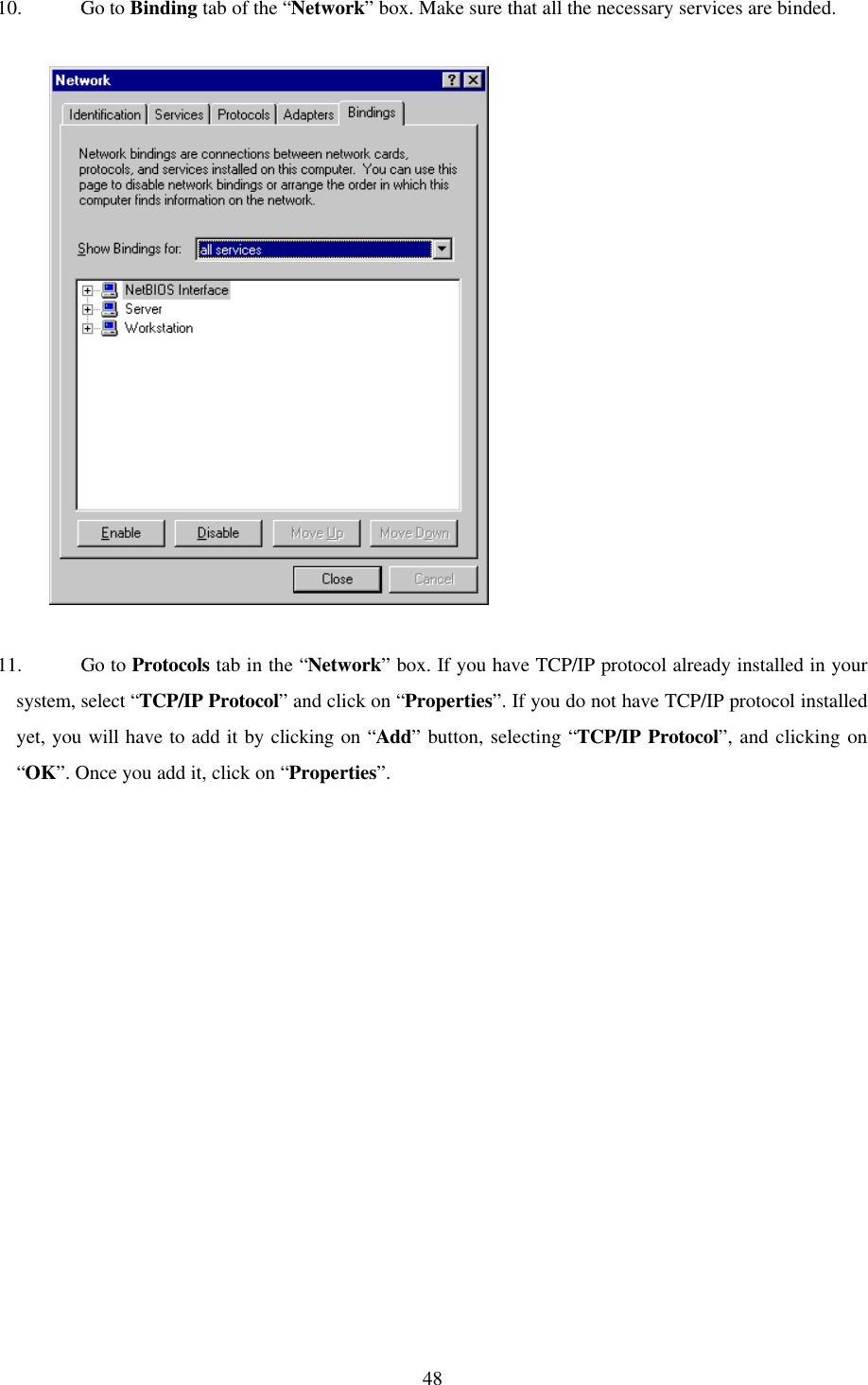
1.
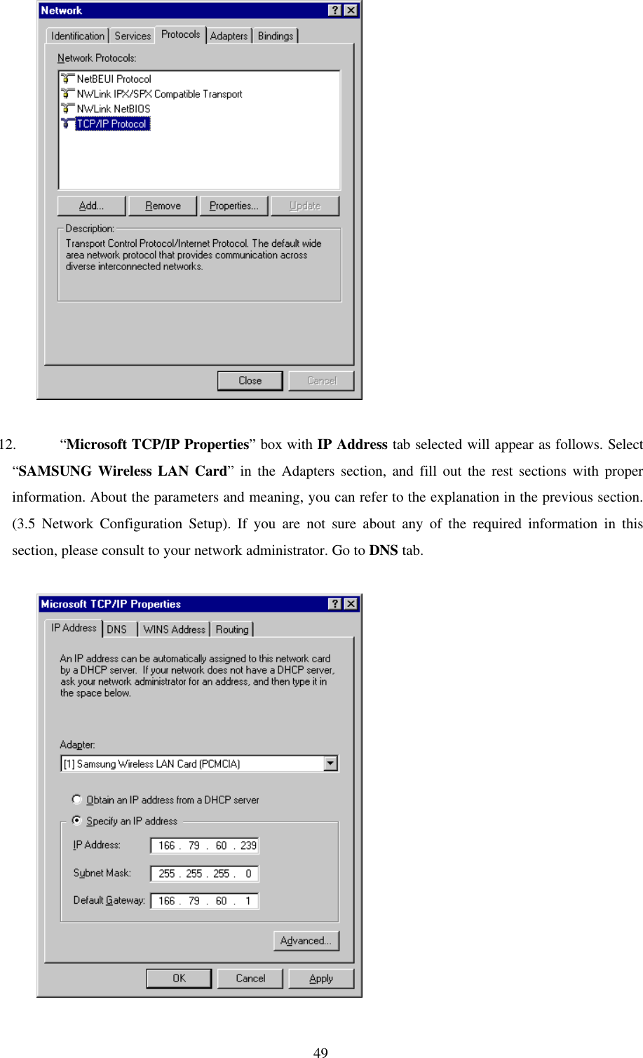
manual
2.
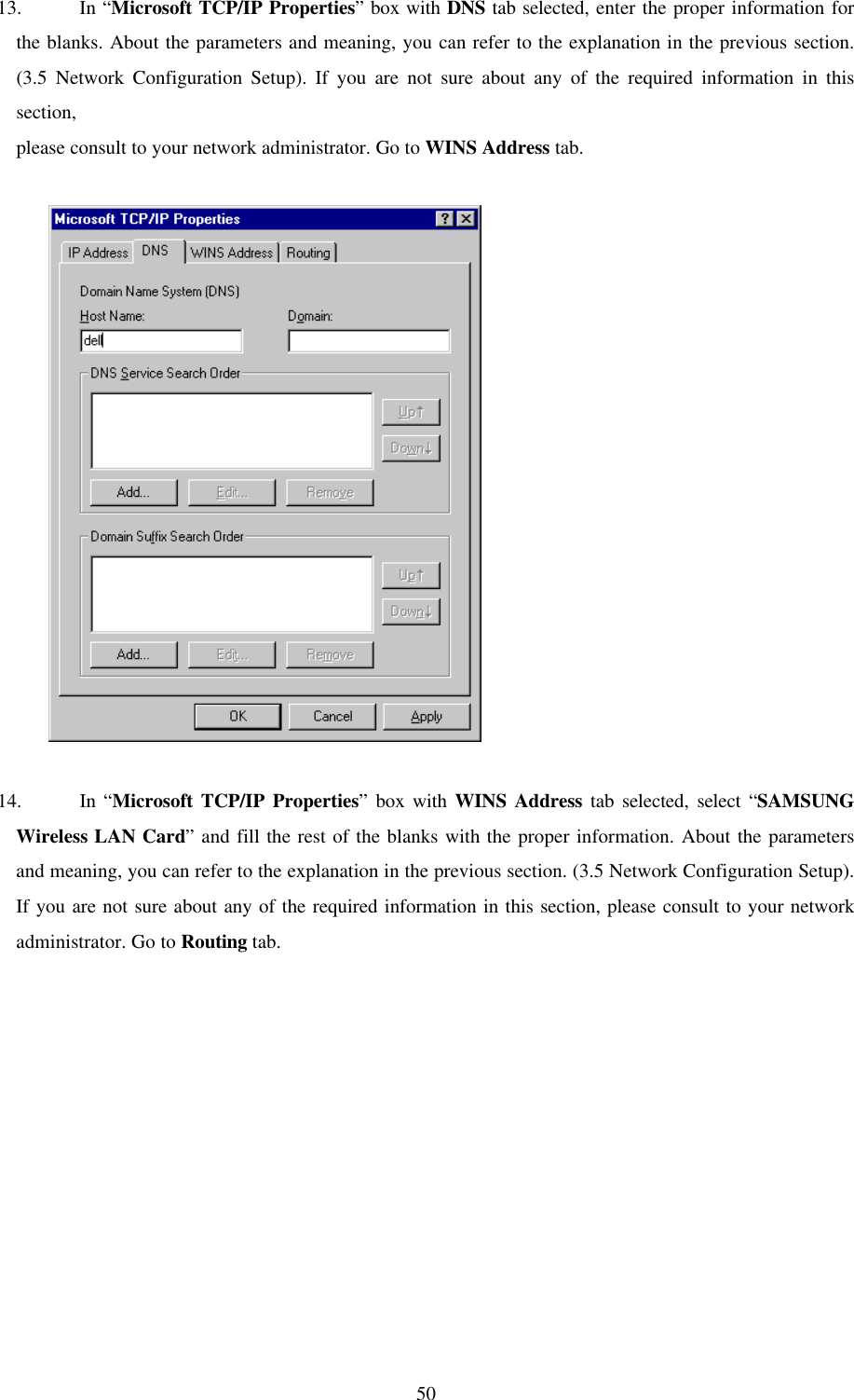
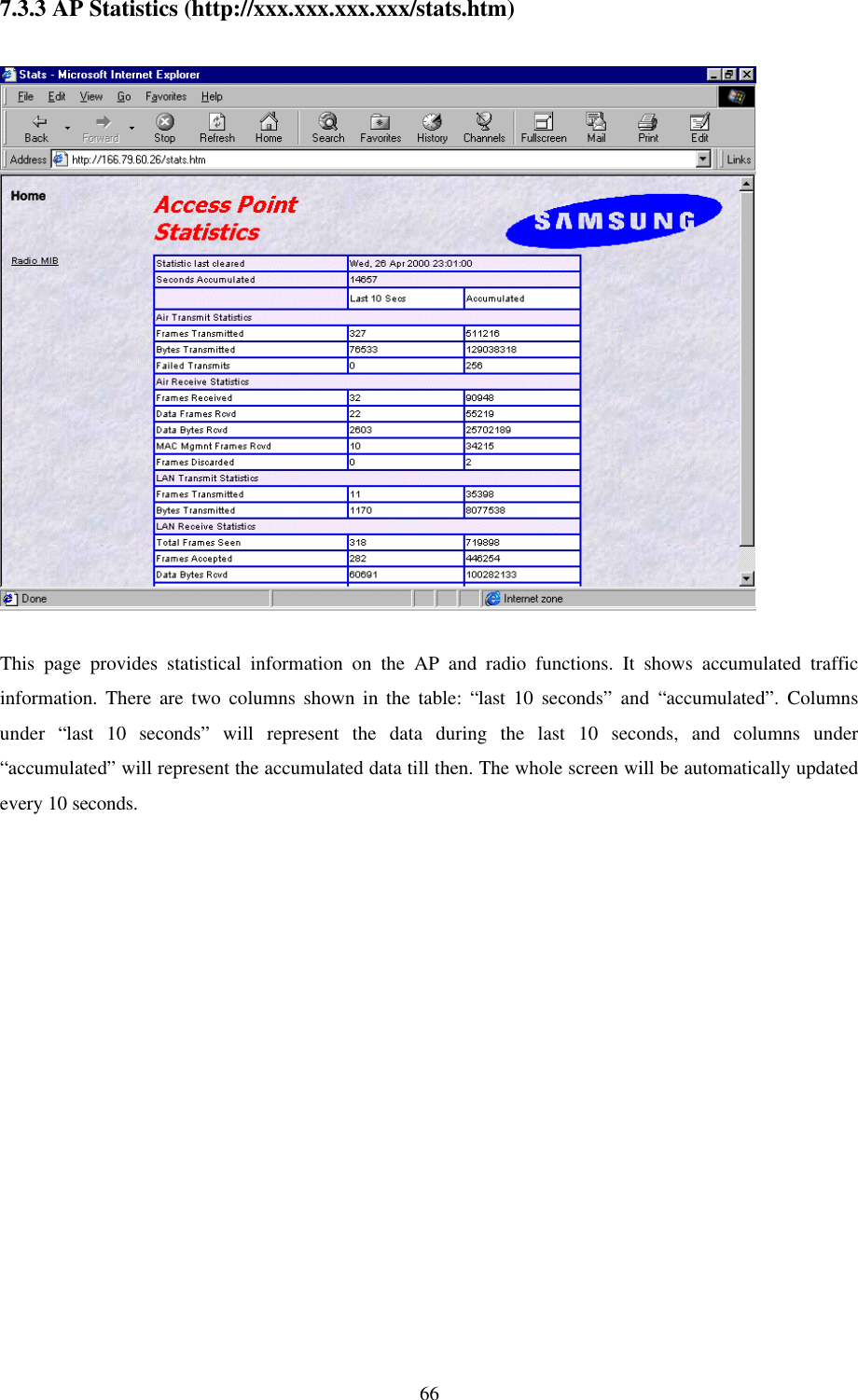
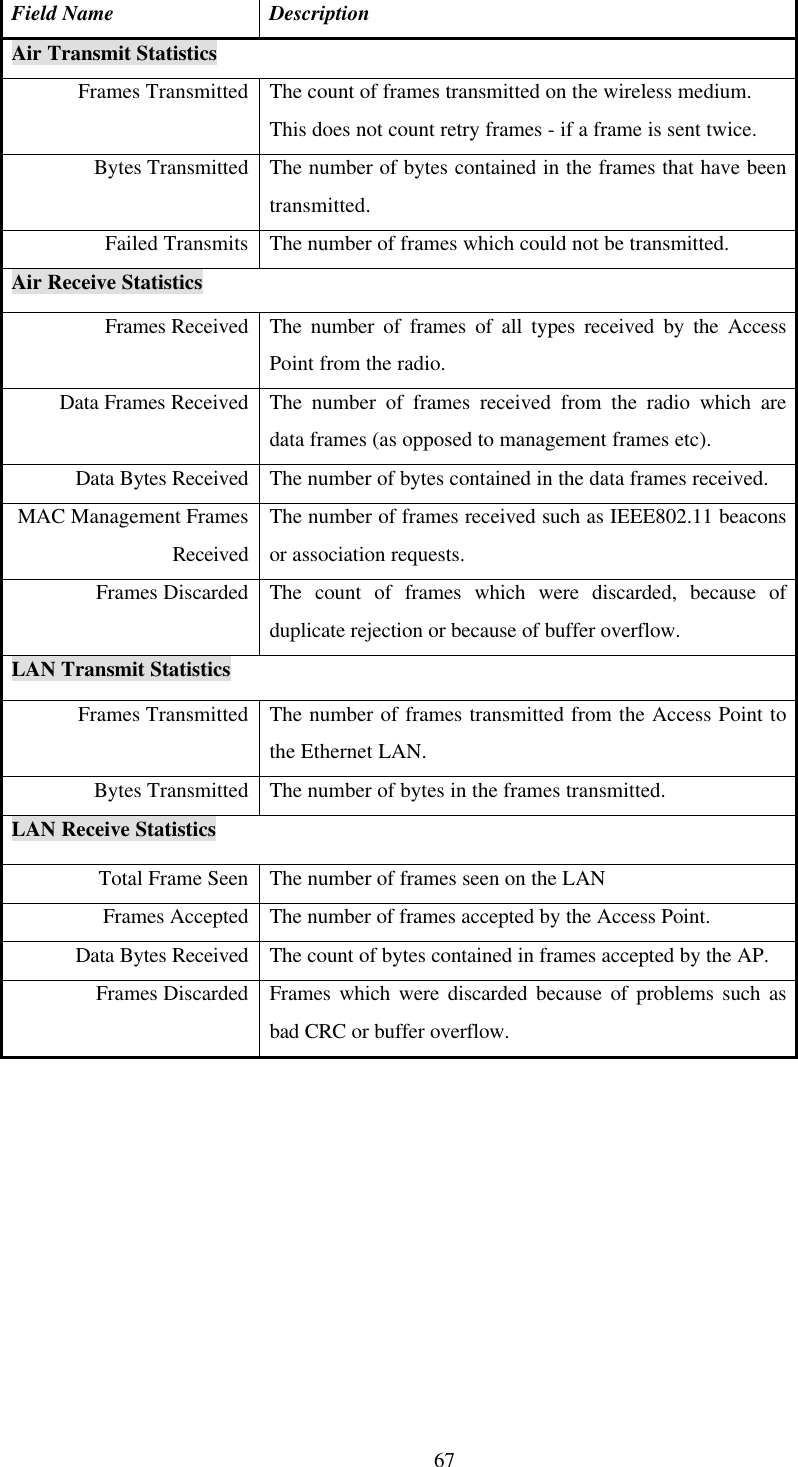
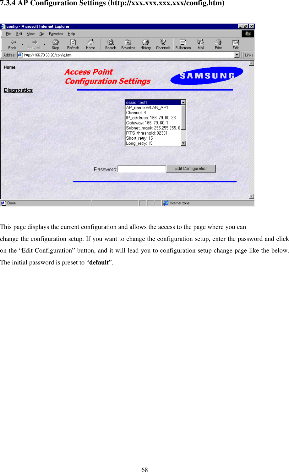
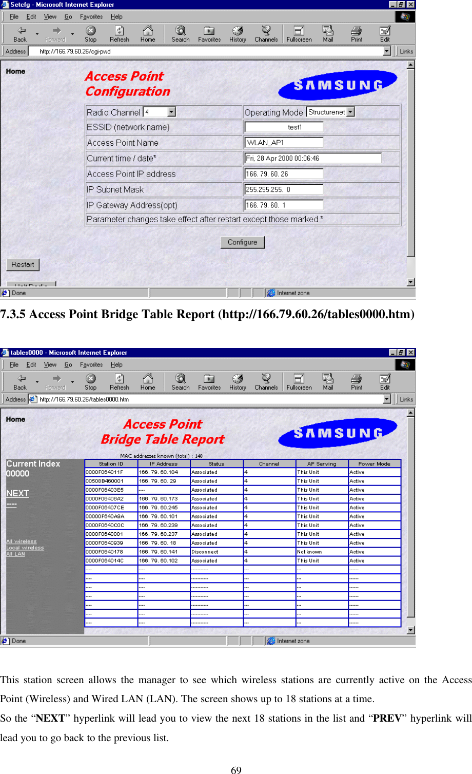
Manual
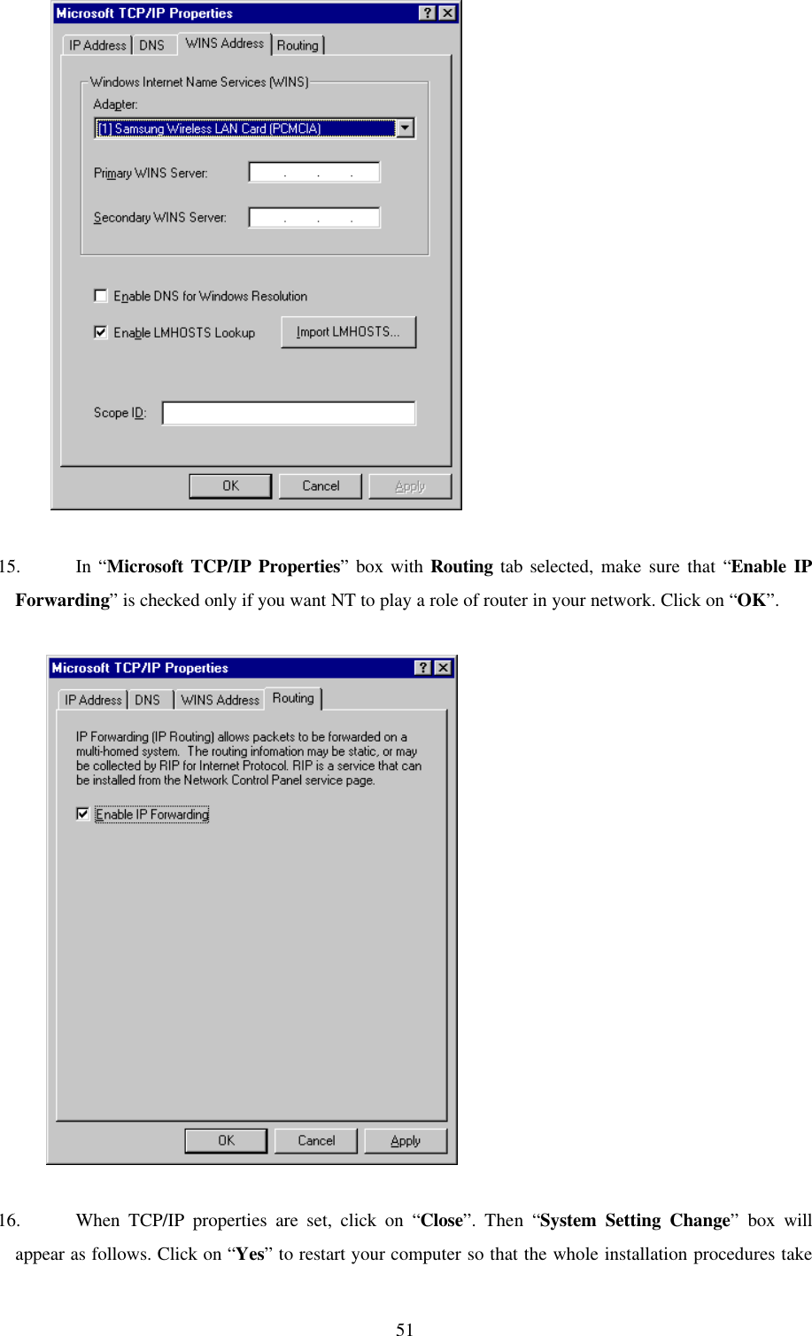
Manual
Navigation menu
Upload a User Manual
Namespaces
Wiki Guide
HTML
PDF
Info
Views
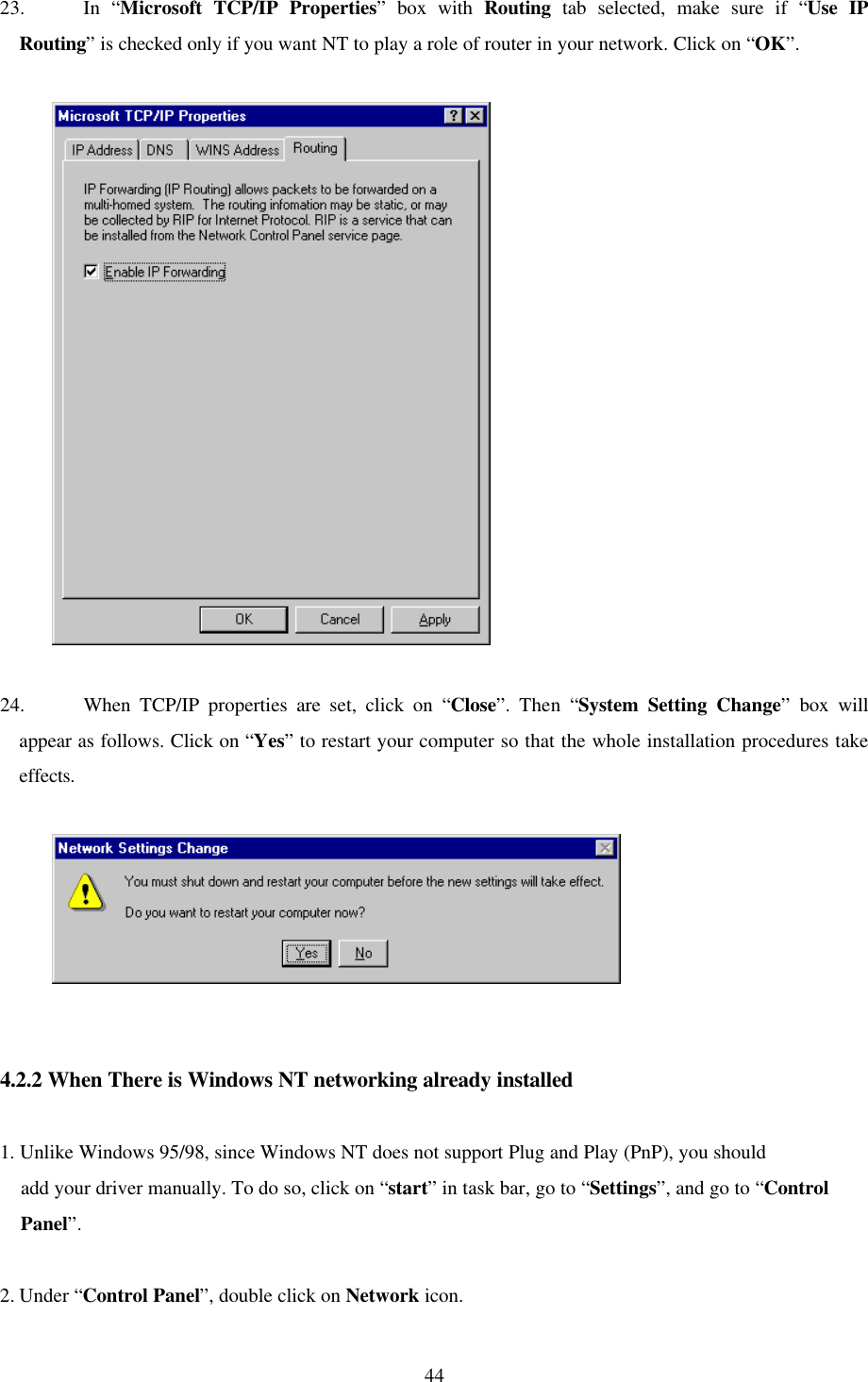
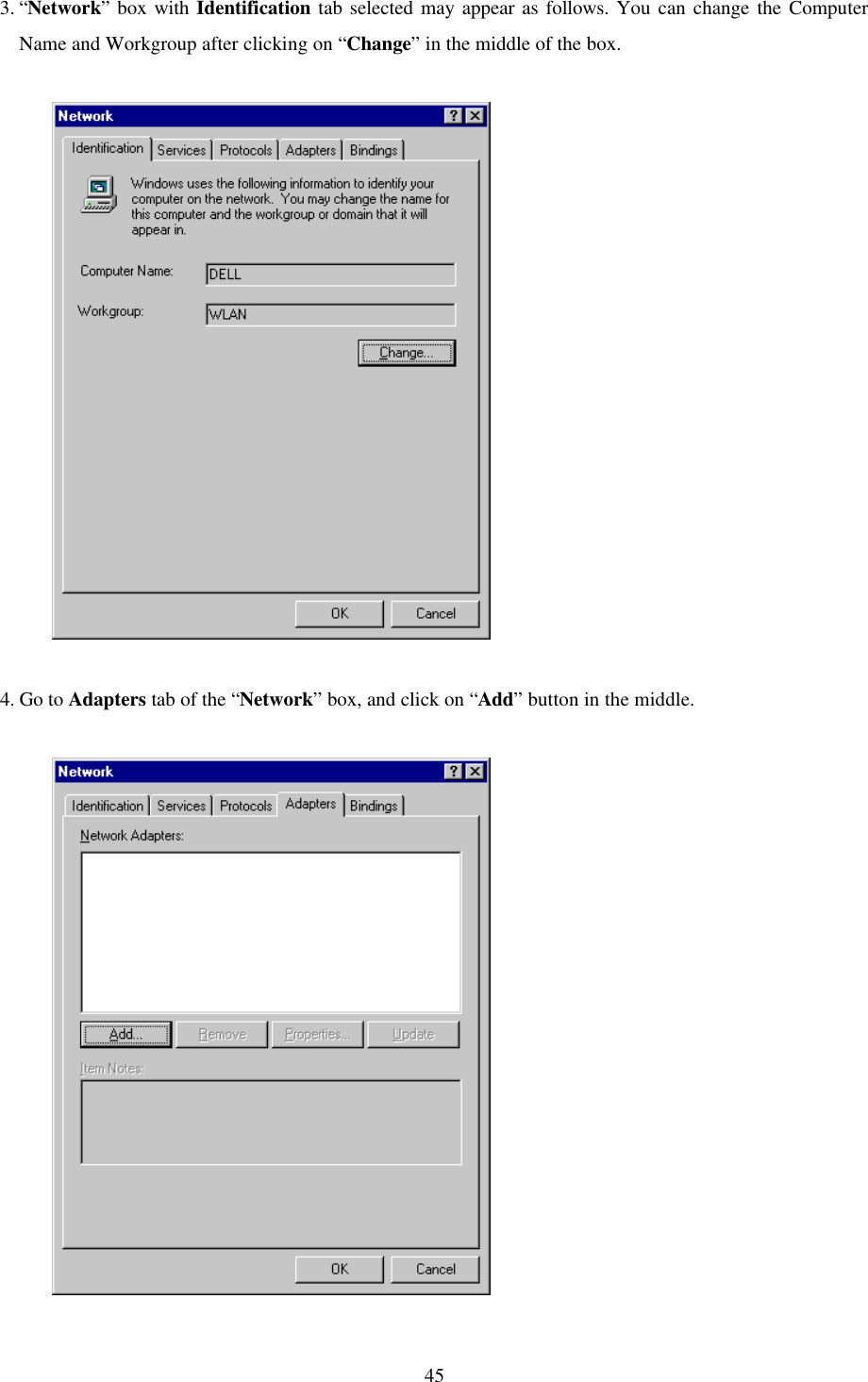
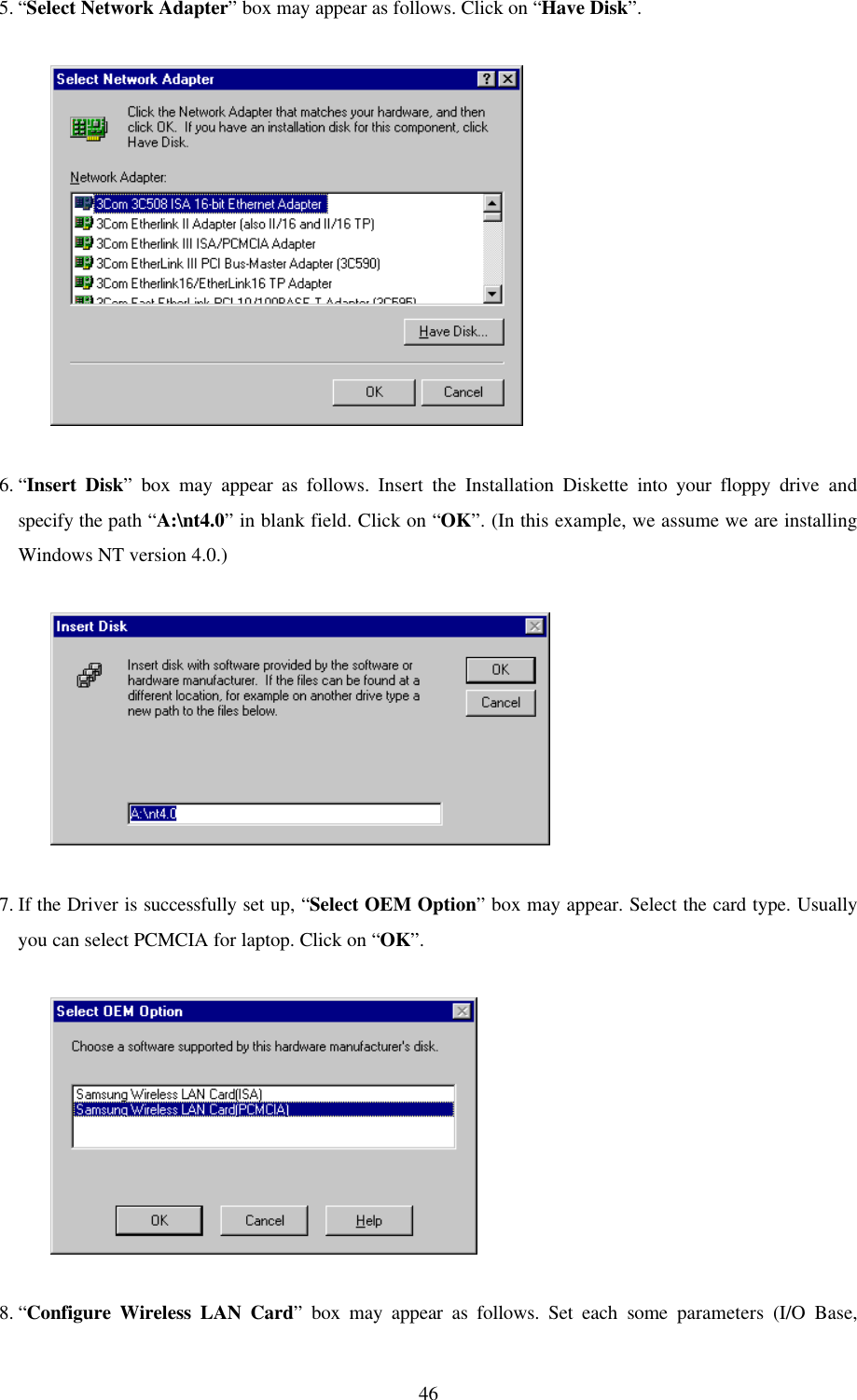
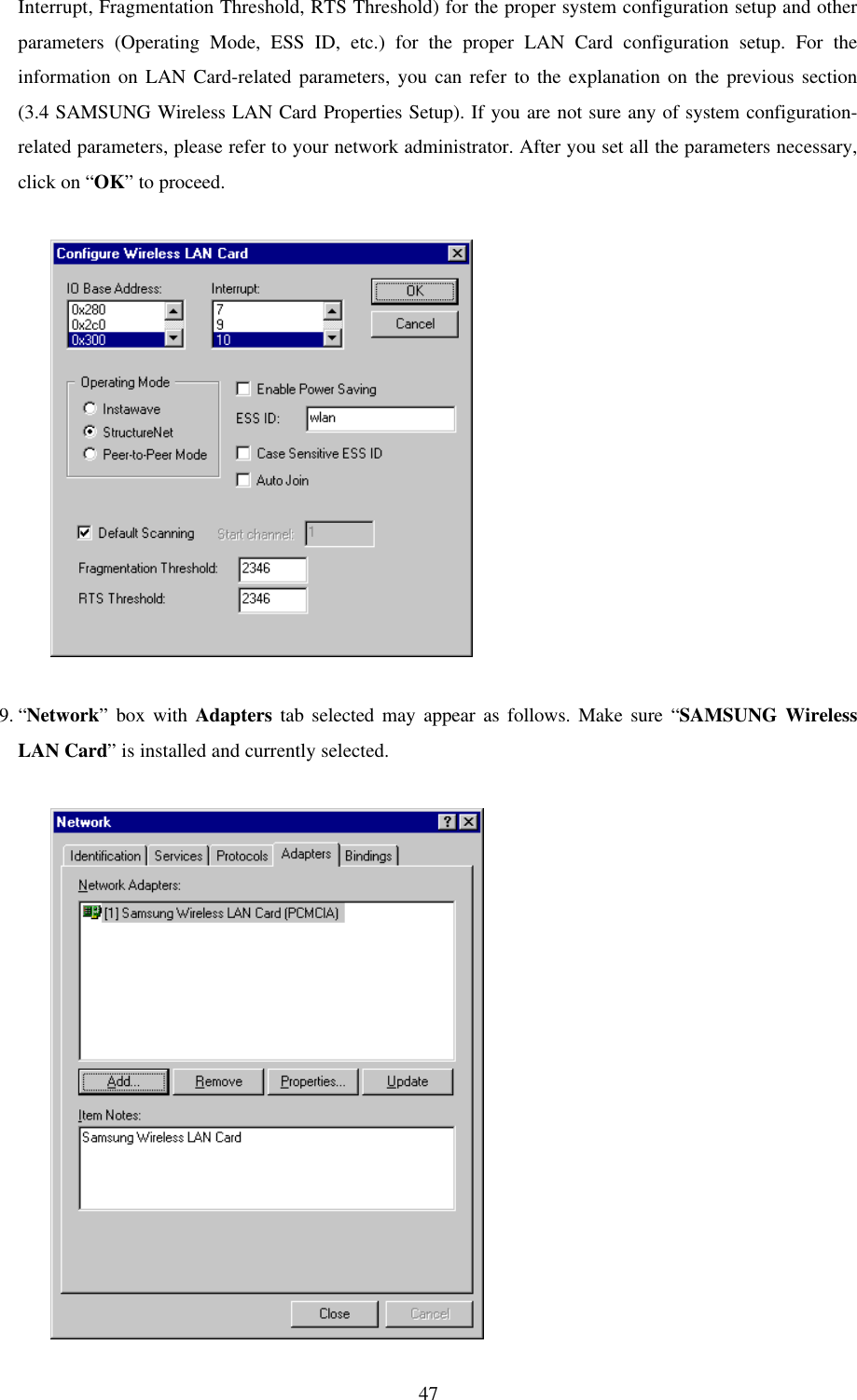
User Manual
Discussion / Help
Navigation
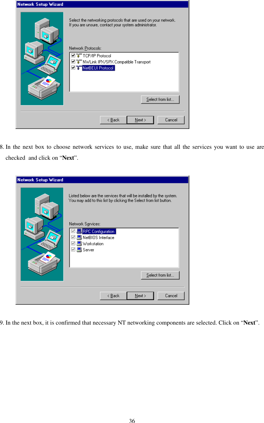
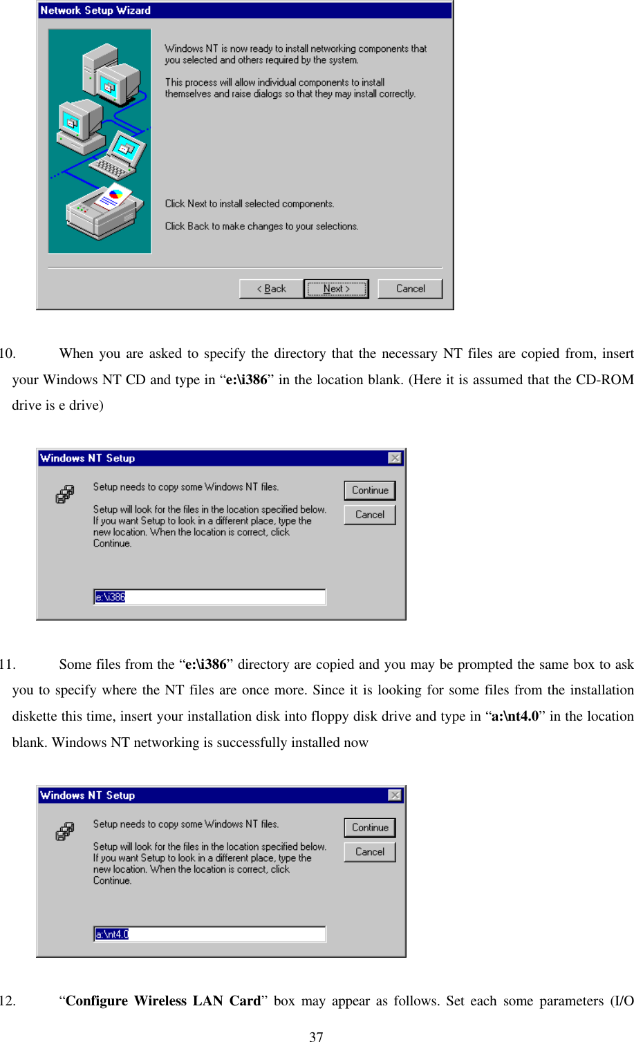
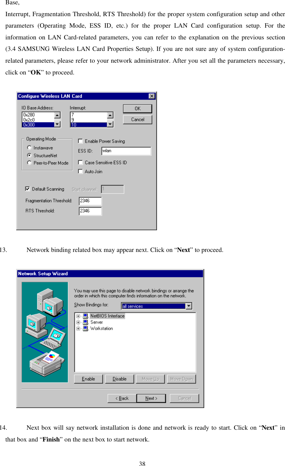
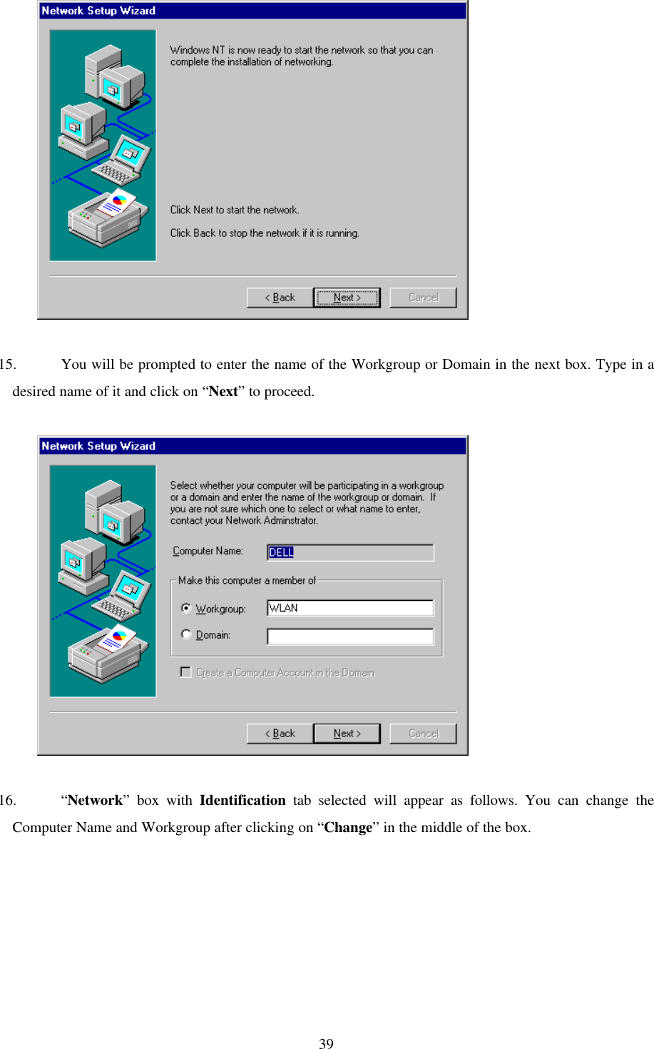
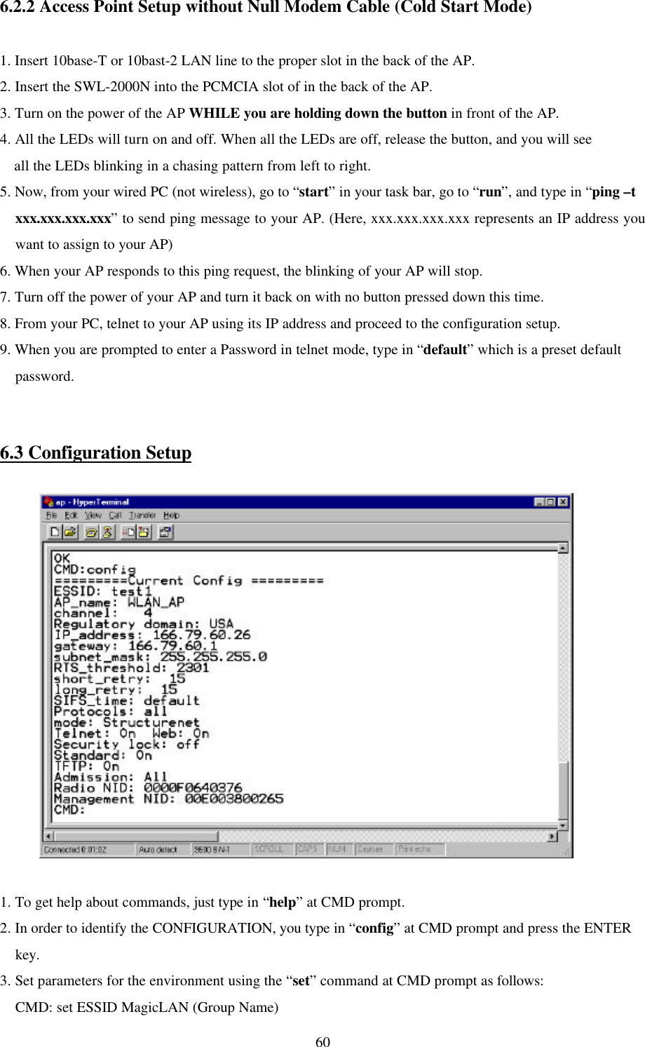


![727.4.2.3 Explanation on various Commands•• help: Displays list of all the commands. Usage: help [command]•• show: Displays the number of attached clients in both wireless and wired LAN. Similar to the “Bridge Table Report” screen of the Web Management Utility.a. Usage: show [A | G | S] - A: List of all known clients attached via wireless LAN. - G: List of all known clients attached via wired LAN. - S: List of all wireless stations. b. The result of the command is list providing the following information. - Net ID: IEEE network address of the client. - State: Current relationship of client with AP (Associated, Disconnected, Detected, is bridging, bridged, Local AP, Unknown). - Channel: Radio channel. - Power: Whether the power of the client is on or off. (On, Off) - Current AP: The Access Point with which the unit is associated. - IP address: IP address of the client.• time: Displays the current date and time and those of last restarted time.• settime: Sets the system time. Usage: “settime HH(hours):MM(minutes):SS(seconds)”• setdate: Sets the system date. Usage: “setdate MM(month):DD(date):YY(year)”• config: Displays the current system settings for configuration. Note that if a configurationchange has been made which requires a system restart to take effect, both the old and the newvalues will be shown.• stats: Displays traffic statistics. Statistics are displayed for the last 10 second interval. To view the cumulative total, use the command line of “stats c”.• logout: After this command has been issued the user must re-enter the password before any more commands can be issued.• ver: Displays version information about the Access Point software.• restart: Reinitializes the SWL-2000AP.• ping: Issues an ICMP Echo request (PING) to the specified IP address. Usage: “ping xxx.xxx.xxx.xxx [yy]”(Here, “xxx.xxx.xxx.xxx” is the destination IP address and yy option will make this pingcommand executed indefinitely.)• nid: nid is the unique number of wireless LAN card, which is also called “MAC Address”. Usage: “nid [add | delete] 123456789abc NAME” / “nid list”](https://usermanual.wiki/Samsung-Electro-Mechanics/SWL-2000N.Manual/User-Guide-58483-Page-73.png)