Samsung Electro Mechanics SWL-2000N PCMCIA Card User Manual Manual
Samsung Electro Mechanics PCMCIA Card Manual
Contents
- 1. manual
- 2. Manual
manual

SAMSUNG
MagicLAN SWL-2000N
User Manual (Ver. 1.0)

1
Notice 1
This manual cannot be reproduced in any form without the prior written permission of
SAMSUNG Electro-Mechanics, Co., Ltd.
SAMSUNG Electro-Mechanics, Co., Ltd. reserves the right to change this manual and the
specifications to improve products without prior notice. So you can get the most recent
software and user documentation for all MagicLAN products on our web site.
• MagicLAN is the trademark of SAMSUNG wireless LAN.
• MS-DOS, Microsoft and Windows are registered trademarks of Microsoft Corporation.
All other brand and product names are trademarks of registered trademarks of their
respective holders.
http://www.MagicLAN.com
Service Dept. +82-331-210-6805
Sales Dept. +82-331-210-6386
SAMSUNG – America Corporation
Western US Marketing Office
85 Tasman Drive
San Jose, CA 95134 USA
Tel: (408)544-5200 Fax: (408)544-4967
Eastern US Marketing Office
LanPAL AKOM Corporation
9 Parklawn Dr.
Bethel, CT 06801
Tel: (203)778-9500 Fax: (203)778-9525
Copyright 1999 SAMSUNG Electro-Mechanics, Co., Ltd.
All rights reserved.

2
Notice 2
The SWL-2000N complies with Part 15 of the FCC rules.
Operation is subject to the following two conditions;
(1) This device may not cause harmful interference.
(2) This device must accept any interference received, including
interference that may cause undesired operation.
Note: The SWL-2000N has been tested and found to comply with the limits for a Class B
digital device and a low power transmitter, according to Part 15 of the FCC Rules. These
limits are designed to provide reasonable protection against harmful interference in a
residential installation. This equipment generates, uses and can radiate radio frequency
energy and, if not installed and used in accordance with the instructions, may cause harmful
interference to radio communications. However, there is no guarantee that interference will
not occur in a particular installation. If this equipment does cause harmful interference to
radio or television reception, which can be determined by turning the equipment off and on,
the user is encouraged to resolve the problem by one or more of the following measures;
- Reorient or relocate the receiving antenna.
- Increase the separation between the equipment and the receiver.
- Connect the equipment to an output on a circuit different from that to
which the receiver is connected.
- Consult the dealer or an experienced radio/TV technician for help.

3
Important Safety Information
l Read these simple guidelines. Breaking the rules may be dangerous or illegal. SAMSUNG is not
responsible for any damages caused by breaking the rules.
l Wireless LAN Card described in this document is approved for use in a wireless local area
network.
l Remember to make backup copies of important data.
l When you are transferring data, keep your laptop computer stationary. Roaming between access
points may break the connection.
l Only qualified service personnel must repair the equipment.
l All wireless devices may get interference, which could affect performance.
l Use approved accessories only. Do not connect incompatible products.
l Use only accessories approved by the wireless LAN Card manufacturer for use with this
particular wireless LAN Card. The use of any other types will invalidate any approval or
warranty applying to the wireless LAN Card, and may be dangerous,
l Use only the region setting appropriate for the area where the wireless LAN Card is used at the
present time. Using the card in any other region or with an incorrect region setting is prohibited
and may be illegal.
l Operation of any radio transmitting equipment, including a wireless LAN Card, may interference
with the functionality of inadequately protected medical devices.
l Do not use the wireless LAN Card on aircraft.
l Do not use the wireless LAN Card at a refueling point.
l Do not use the wireless LAN Card near fuel or chemicals.
l Do not use the wireless LAN Card where blasting is in progress.
l Do not use the wireless LAN Card when the use of wireless device may cause interference or
danger.
l Do not use the wireless LAN Card where the use of cellular terminals is prohibited.

4
Table of Contents
1. MagicLAN Installation ……………...…………………………………………………... 7
1.1 Introduction …………………………..……………………………………………...
7
1.2 Technical Background ……………………..……………………………………….. 7
1.3 MagicLAN Overview ……………………………..………………………………. 10
2. Before Installation ……………………………………………………………………... 11
2.1 What’s in your Package …………………………………………………………… 11
2.2 System Requirement ……………………………………………………………… 11
3. MagicLAN Installation for Windows95/98 ……………………………………………. 12
3.1 Installation Overview ……………………………………………………………… 12
3.2 Hardware Installation ……………………………………………………………… 13
3.2.1 Notebook PC Adapter Card (SWL-2000N) ………………………………….. 14
3.2.2 Access Point (SWL-2000AP) ………………………………………………... 14
3.3 Software Installation ……………………………………………………….……… 15
3.3.1 Driver Setup ………………………………………………………………….. 15
3.4 MagicLAN Wireless LAN Card Properties Setup ………………………………… 20
3.4.1 Before Wireless LAN Card Properties Setup ………………………………... 20
3.4.1.1 Basics regarding the Properties Setup ……………………………………….. 20
3.4.1.2 Meanings of the Properties Setup Options …………………………………… 20
3.4.2 Setting Network Properties for “Peer-to-Peer” mode ………………………... 21
3.5 Network Configuration Setup ……………………………………………………... 23
3.5.1 Network Configuration Setup Overview …………………………………….. 23
3.5.2 Before TCP/IP Networking Configuration Setup …………………….……… 23
3.5.2.1 What you should know before Configuration ………………………………... 23
3.5.2.2 What you should have in your hands to proceed further …………………….. 24
3.5.3 Setting Network Properties for “StructureNet” mode ……………………….. 25
3.5.4 Setting Network Properties for “Instawave” mode ………………………….. 26
3.5.5 TCP/IP Networking Configuration Setup …………………………….……… 27
3.5.5.1 TCP/IP Installation …………………………………………………………… 27
3.5.5.2 TCP/IP Properties Setup ……………………………………………………... 30
4. MagicLAN Installation for Windows NT ……………………………………………… 34

5
4.1 Hardware Installation ……………………………………………………………… 34
4.2 Software Installation ……………………………………………………….……… 34
4.2.1 When there is no Windows NT Networking installed yet …………………… 34
4.2.2 When there is Windows NT networking already installed …………………... 44
5. Packet Driver Installation for MS-DOS ……………………………………………….. 52
5.1 Copy the Packet Driver ……………………………………………………………. 52
5.2 Setup AUTOEXEC.BAT ………………………………………………………….. 52
5.3 Setup MAGICWAV.CFG ………………...……………………………………….. 52
6. Access Point(AP) Installation ………………………………………………………….. 56
6.1 Before Access Point(AP) Installation ……………………………………………... 56
6.1.1 Access Point(AP) …………………………………………………………….. 56
6.1.2 What you need for the Installation …………………………………………… 56
6.2 Access Point(AP) Installation ……………………………………………………... 56
6.2.1 Access Point Setup using Null Modem Cable ……………………………….. 56
6.2.2 Access Point Setup without Null Modem (Cold Start Mode) ……………….. 59
6.3 Configuration Setup ……………………………………………………………….. 59
6.4 Parameter Setup …………………………………………………………………… 60
6.5 Null Modem Cable Configuration ………………………………………………… 62
6.6 Diagnostic Methods ……………………………………………………………….. 62
7. Management Utilities(Web & Telnet) …………………………………………………. 63
7.1 About Management Utilities ……………………………………………….……… 63
7.2 Hyper Terminal Management Utility ……………………………………………... 63
7.3 Web Management Utility ………………………………………………….………. 63
7.3.1 Web Management Utility Overview ………………………………….……… 63
7.3.2 AP Status Report(http://xxx.xxx.xxx.xxx) …………………………………… 64
7.3.3 AP Statistics(http://xxx.xxx.xxx.xxx/stats.htm) ……………………………... 65
7.3.4 AP Configuration Settings(http://xxx.xxx.xxx.xxx/config.htm) …….………. 67
7.3.5 Access Point Bridge Table Report(http://169.79.60.26/tables0000.htm) ……. 68
7.4 TELNET Management Utility …………………………………………………….. 70
7.4.1 Telnet Management Utility Overview ……………………………………….. 70
7.4.2 Various Commands and Usage ……………………………………….……… 70
7.4.2.1 Usage of the command line …………………………………………………... 70
7.4.2.2 All Possible Commands ……………………………………………………… 70
7.4.2.3 Explanation on various Commands ………………………………………….. 71
6
8. Miscellaneous Features ………………………………………………….……………... 73
8.1 Connection Check ………………………………………………………….……… 73
8.1.1 When successfully connected to Network through AP ……………….……… 73
8.1.2 When failed to connect to Network through AP ……………………………... 73
8.2 Performance & AP Information Check ……………………………………………. 73
8.3 Brief Troubleshooting ……………………………………………………………… 74
8.4 Specifications ………………………………………………………………………. 75
8.4.1 Physical Specifications ……………………………………………….……… 75
8.4.2 Radio Characteristics ………………………………………………………… 75
8.4.3 Network Characteristics ……………………………………………………… 75

7
1. MagicLAN Introduction
1.1 Introduction
Thank you for your purchase of SAMSUNG MagicLAN (SWL-2000N) Wireless LAN Adapter.. Installing
card allows the computer to join a wireless network based on the IEEE 802.11 wireless LAN standard. You
will be surprised how easy for you to be a part of network with no bother of twisted cables.
1.2 Technical Background
• What is IEEE 802.11?
The IEEE 802.11 specification is a wireless LAN standard developed by the IEEE (Institute of Electrical and
Electronic Engineering) committee in order to specify an “over an air” interface between a wireless client
and a base station or Access Point, as well as among wireless clients.
Like other IEEE 802 families, IEEE 802.11 specification addresses both Physical (PHY) layer and Media
Access Control (MAC) layer.
• IEEE 802.11 Physical (PHY) Layer
At the PHY layer, IEEE 802.11 defines three physical characteristics for LAN: diffused infrared, Direct
Sequence Spread Spectrum (DSSS), and Frequency Hopping Spread Spectrum (FHSS). While the infrared
PHY operates at the baseband, the other two PHYs operate at the 2.4GHz ISM (Industrial, Scientific, and
Medical) band, which can be used for operating wireless LAN devices without the need for end-user
licenses. In order for wireless devices to be interoperable, they have to be conform to the same PHY
standard.
• IEEE 802.11 Media Access Control (MAC) Layer
The IEEE 802.11 MAC Layer is mainly concerned with rules for accessing the wireless medium. There are
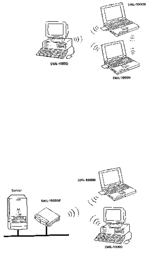
two network architectures defined: StructureNet Network and Peer-to-Peer Network.
8
• Peer-to-Peer Network
Peer-to-Peer Network is an architecture that is used to support mutual communication among wireless
clients only. Since Peer-to-Peer Network does not support access to wired networks, it does not need an
Access Point to be a part of the network. You can use the network immediately after setting up the operating
mode using the supplied network driver.
• StructureNet Network
StructureNet Network is architecture to provide communication between wireless clients and wired network
resources. The transition of data is defined by an Access Point (AP) and the associated wireless clients. So a
wireless client can access all the services that are available for a regular wired LAN by using Access Point
(AP).
• Instawave Network
Instawave Network is architecture to provide both Peer-to-Peer Network features and StructureNet Network
feathers at the same time. In other words, wireless clients on the network can directly communicate with
each other while they can also access wired LAN clients through AP if they want. Instawave Network is a
good choice for small networks that need maximum flexibility and simplicity.
9
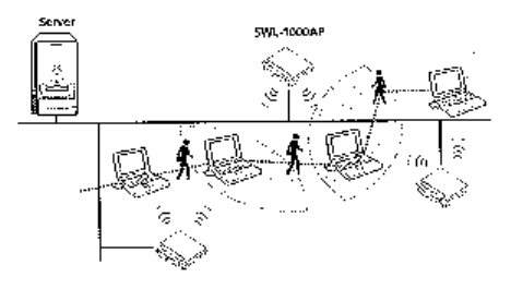
• Roaming
Roaming is a service that allows wireless clients to use the network in motion by automatically moving the
connection to an old Access Point into a new Access Point when the clients enter into a new cell.
• Scanning, Beaconing & ESS ID
When a wireless client is initialized, it is necessary for it to find and communicate with the correct group for
wireless devices, including Access Point (AP). At this point, it may search for all the frequency channels and
this process is called “scanning.”
There may be multiple APs and network operating at the same time. It may be necessary to ensure that the
station joins with the correct network during the scanning process. To achieve this, each AP is assigned to
be part of a logical group called the Extended Service Set (ESS). The name of this logical group is the ESS
ID. When roaming is operating, there may be several Access Points as part of the same ESS.
After powering up, the wireless client will listen on its default frequency channel. It will be listening for
“beacons” sent by another wireless station or AP. Here, a beacon is a short message containing the ESS ID
that will be broadcast roughly ten times a second.
When the wireless station hears a beacon, if the ESS ID in the beacon matches its own, the client knows that
it is on the correct channel and can communicate with its group. If no beacons are seen, or if the ESS ID
does not match, the wireless client may move to the next frequency channel and repeat this listening
procedure. If all frequency channels have been searched with no matched ESS ID found, it will assume that
it is the first client in the group to wake up and will return to its default channel and start to issue beacons
itself.
In DSSS, this scanning process occurs at start up and may also occur when the client roams between APs.

10
1.3 MagicLAN Overview
• The SWL-2000N (for Notebook) is a wireless LAN adapter card that provides wireless connection between
PCs.
• The MagicLAN is designed to operate with IEEE 802.11 (wireless LAN International Standard) wireless
compliant radio cards and uses a CSMA/CA (Collision Sense Multiple Access with Collision Avoidance)
algorithm as the media access scheme, which makes high speed communication with minimal collision
possible.
• The MagicLAN supports DSSS (Direct Sequence Spread Spectrum). This is a radio technique, which
scrambles the data prior to transmission and uses a correlation technique on receiving to improve the signal
to noise ratio and makes it possible to communicate in the office having a wall and a compartment.
• The function of the MagicLAN SWL-2000AP (Access Point) is to transfer information from a wired LAN
to a wireless LAN and vice versa. When operating, the MagicLAN AP is invisible to most users (Normally,
unless the user is an administrator, the MagicLAN AP cannot be seen or accessed by users on the network).
• The SWL-2000N for Notebook PC is small and portable as a roaming function is provided for users who
need network services while maintaining mobility.
• The MagicLAN Adapter has three LED’s (Light Emitting Diodes) on the part of the card: Power, Tx, and
Rx. The red Power LED will illuminate when the power is applied. The orange Tx LED and green Rx LED
will illuminate when the date is transmitted out and in respectively.
• The MagicLAN supports various network software. The network driver is provided to support most
network software such as MS-DOS Packet, Windows 95/98, and Windows NT 3.51/4.0.
11
2. Before the Installation
The following section will assist you in successfully installing your wireless network adapter card. You will
first install the hardware and software, then set network properties to accommodate resource sharing and to
select the type of wireless network you wish to install. The MagicLAN can be easily installed and used,
without bother to connect cables and maintain them to use network as a wired LAN requires.
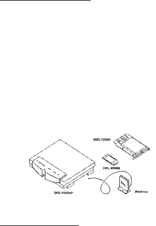
2.1 What’s in Your Package
Please check the contents of the box to make sure everything is included and ready for use. Here is the list of
what you should have in your package:
• SWL-2000N (PCMCIA Card) Adapter
• SWL-2000N Installation Diskette (Driver Diskette)
• User’s Manual
• SWL-2000AP (Each Access Point requires a SWL-2000N adapter card for operation)
• Power Adapter (SWL-2000AP only)
• SWL-2000AP Utilities Diskette (SWL-2000AP only)
• External Antenna (Optional)
2.2 System Requirement
• Operating System: MS Windows 95 / Windows 98 / Windows NT3.51/ Windows NT4.0
• Computer System with a 31/2-inch floppy disk drive
• For Notebook PC Adapter Card (SWL-2000N):
The computer system should have PCMCIA Type II or Type III card slot.

12
3. MagicLAN Installation for Windows 95/98
3.1 Installation Overview
Here are some steps you will perform in establishing your wireless network connection:
• Install the hardware.
- For the StructureNet mode, you must install an Access Point (SWL-2000AP) first.
Then install the adapter (SWL-2000N).
• Install the software using the included installation diskette.
• Install the network protocol(s) required to communicate on your network. Most likely you
will need the TCP/IP protocol.
13
3.2 Hardware Installation
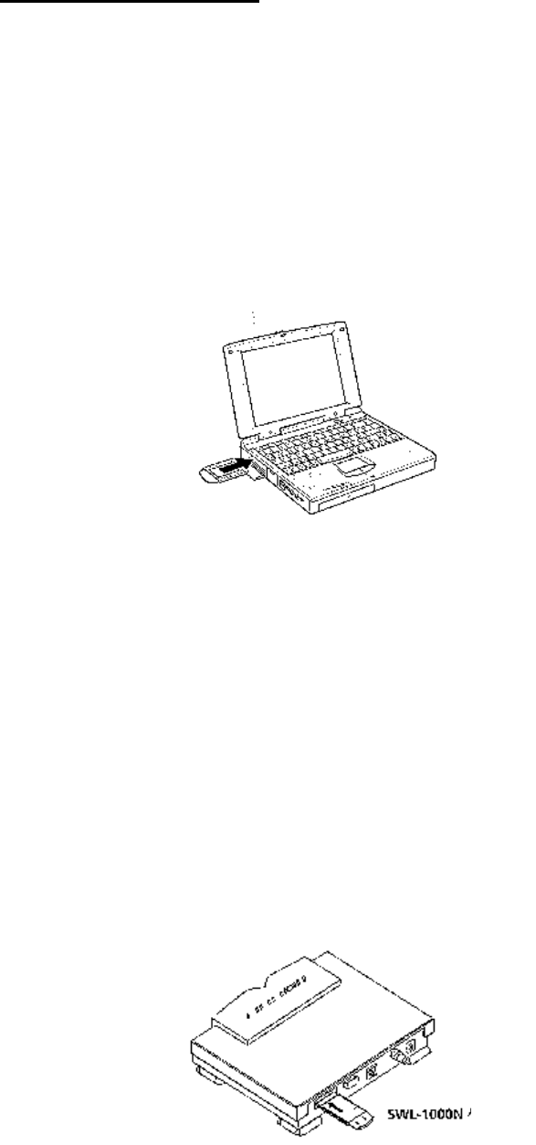
3.2.1 Notebook PC Adapter Card (SWL-2000N)
• You can install the card whether the power of the Notebook is on or off.
• Insert the SWL-2000N adapter card into the PCMCIA slot.
(A pleasant “cheep” sound indicates the regular operation. A low monotonous tone indicates
a failure in recognition.)
• If you see red Power LED illuminating and green Rx LED is blinking, you are now ready to
proceed to software setup.
3.2.2 Access Point (SWL-2000AP)
• An Access Point is equipped with an Ethernet adapter supporting 10base-T, 10base 2 and a
MagicLAN wireless LAN adapter card.
• Insert the MagicLAN card (SWL-2000N) into the PCMCIA slot of the Access Point
(SWL-2000AP)
• Connect the network cable to Ethernet port (10base-T or 10base 2) on the back of the Access
Point.
14
• Connect the power adapter, and now you are ready to use the MagicLAN Access Point.
15
3.3 Software Installation
3.3.1 Driver Setup
(The dialog box pictures used in this section is from Windows 98, and the ones from Windows 95 may be
slightly different.)
1. Start your PC and allow Windows95/98 to fully load. Since you must already have installed the
MagicLAN Adapter in the previous step, an “Add New Hardware Wizard” box will appear.
2. If you use PCMCIA-compatible notebook and have not installed the SWL-2000N adapter yet, insert the
adapter to the slot now, and you will see an “Add New Hardware Wizard” box.
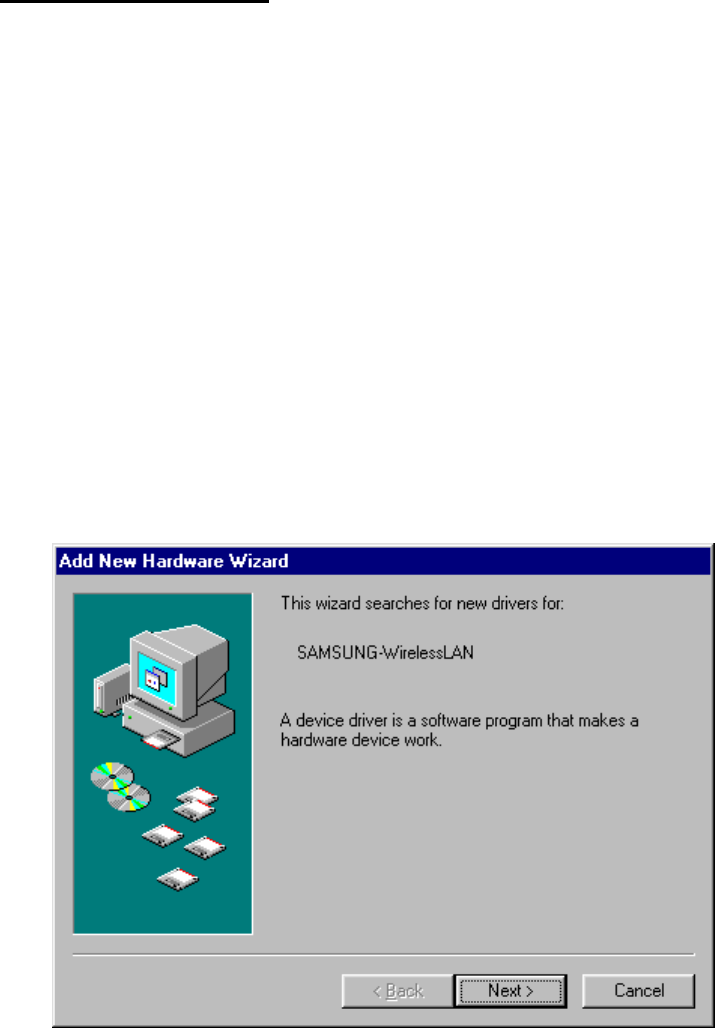
3. In “Add New Hardware Wizard” box, be sure SAMSUNG-WirelessLAN appears as a new device name
as the following box shows.
4. Insert the MagicLAN (SWL-2000N) Installation Diskette into your floppy drive. Click on “Next”.
16
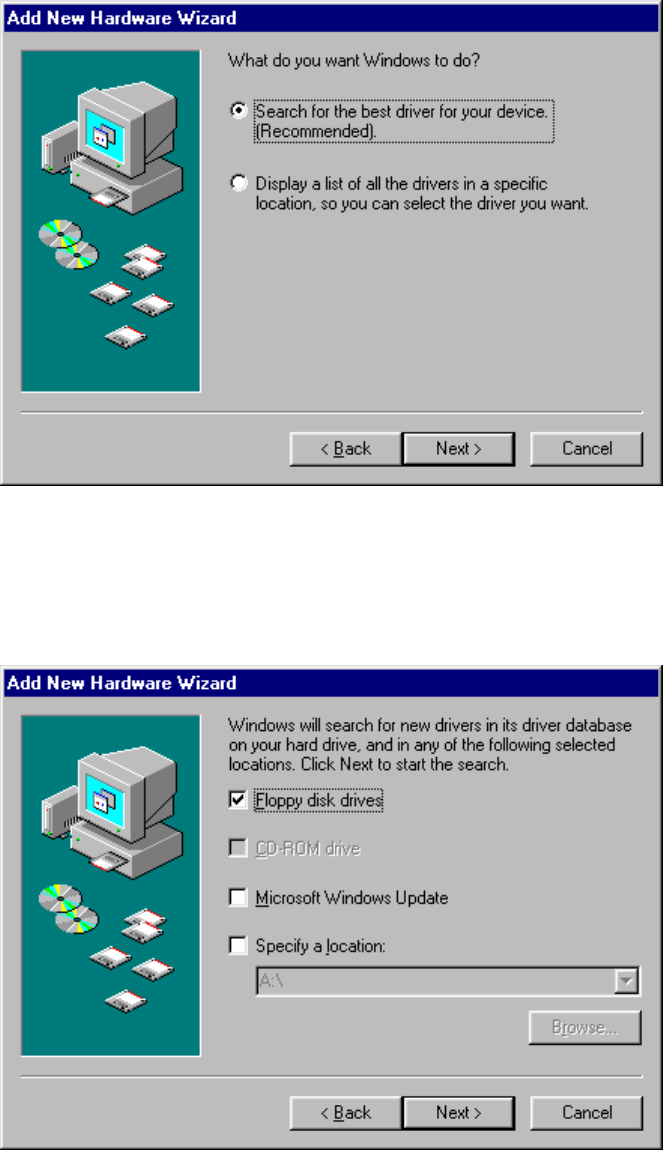
5. Windows 95/98 will present a list of drivers and optionally allow you to specify a location
where it can find the appropriate driver software for the device. The following dialog box
will appear if you use Windows98. Be sure the MagicLAN (SWL-2000N) Installation
Diskette is in floppy drive and “Search for the… (Recommended)” option is selected.
Click on “Next”. (Windows95 has a slightly different display, and you should select a “Have
Disk” option instead.)
6. Next, “Add New Hardware Wizard” box may appear as follows. Be sure the MagicLAN
(SWL-2000N) Installation Diskette is in floppy drive and Floppy disk drives option is
checked as follows. Click on “Next”.
17
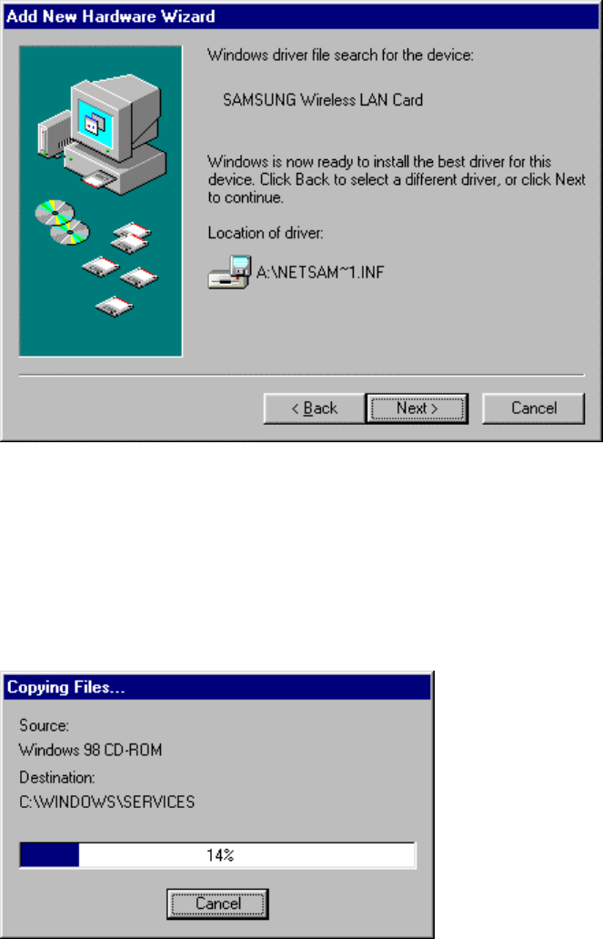
7. If the proper driver was successfully found on the floppy disk, “Add New Hardware
Wizard” box may appear as follows. Click on “Next”.
8. Windows95/98 will now copy files from the floppy disk and may prompt you for the location
for the Windows95/98 installation CD or files. Depending on how your computer was
configured by the manufacturer, you may need to insert the Windows CD into your CD-ROM
drive at this step. While files are being copied, you will see “Copying Files…” box similar to
the one below.
18
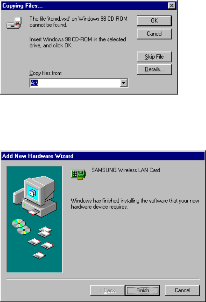
9. While copying files, the following box may appear requesting you to specify where the
some files are located. In the drop-down choice box below, select “A:\” where the
MagicLAN (SWL-2000N) Installation Diskette is located. Click on “OK”.
10. When the driver and all the required Windows95/98 software components are loaded,
you will see the box similar to the one below, which indicates that the driver for
“SAMSUNG Wireless LAN Card” has been successfully installed. Click on “Finish”.
19
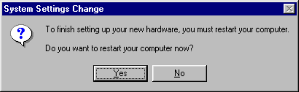
11. Finally, “System Settings Change” box will appear, asking if you wish to restart your
computer now. Remove the MagicLAN (SWL-2000N) Installation Diskette from your
floppy drive. Since you are done with the Installation Diskette, place it in a safe place for
later use. Now, Click on “No” to proceed to MagicLAN Wireless LAN Card Properties Setup
before you restart your computer.

20
3.4 MagicLAN Wireless LAN Card Properties Setup
3.4.1 Before MagicLAN Wireless LAN Card Properties Setup
3.4.1.1 Basics regarding the Properties Setup
• Peer-to-Peer Operating Mode:
Multiple wireless clients can directly communicate with each other without AP.
• StructureNet Operating Mode:
Wireless clients can communicate with each other or with clients on another wired network
always through AP.
• Instawave Operating Mode:
Multiple wireless clients using the same channel can directly communicate with each other,
And they also can communicate with clients on another wired network through AP. In the
second case, it is automatically set up which AP will be used for it.
• Roaming:
One feature of StructureNet operating mode that effortlessly moves between APs that are on
different channels but have the same ESS ID.
• From your network administrator, you should find out ESS ID of the AP and channel number
that you are supposed to use.
3.4.1.2 Meanings of the Properties Setup Options
• Default Scanning / Start Channel: Option in StructureNet and Peer-to-Peer Network)
StructureNet operating mode enables clients to automatically search for new Access Point.
In Default Scanning mode, the wireless client begins the search with Channel 1. The client
then searches all consecutive channels until it finds a new AP with the same ESS ID. If you
want to start the search from a specific channel other than channel 1, you can deselect the
Default Scanning check box and enter the desired channel number in a blank for Start
Channel. This Start Channel entry will be helpful when multiple APs are within range of
each other and you desire to connect to a specific AP among them.
• Enable Power Saving: Option in StructureNet Network
Power save mode will keep the wireless LAN adapter in a low power standby state when there
is no data transfer. This Enable Power Saving option is mainly to extend the operating time
of portable battery operated device such as laptop computers, even sacrificing the effective
throughput of the wireless connection. So you should test both with and without power saving
enabled to see if this option satisfies your needs.
21
• Case sensitive ESS ID: Option in StructureNet and Peer-to-Peer Network
When entering ESS ID, you can make it case sensitive by checking Case sensitive ESS ID
check box.
• Auto join: Option in StructureNet and Peer-to-Peer Network
When Auto join option is selected, the wireless client will associate with whatever access
point is within range and has the best signal independent of the ESS ID setting. Since you
may not use the same AP as described in the “Access Point Client Properties” box, you can
check which AP and ESS ID you are actually using by double clicking the task bar status icon
to display the wireless client status box.
3.4.2 Setting Network Properties for “Peer-to-Peer” mode
1. Right click on your “Network Neighborhood” icon and click on “Properties”.
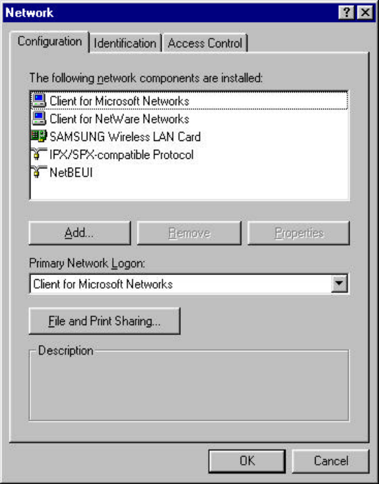
2. “Network” box will appear with Configuration tab selected as follows. In the list in the box,
click on “SAMSUNG Wireless LAN Card” and “Properties” button in the middle
sequentially.
22
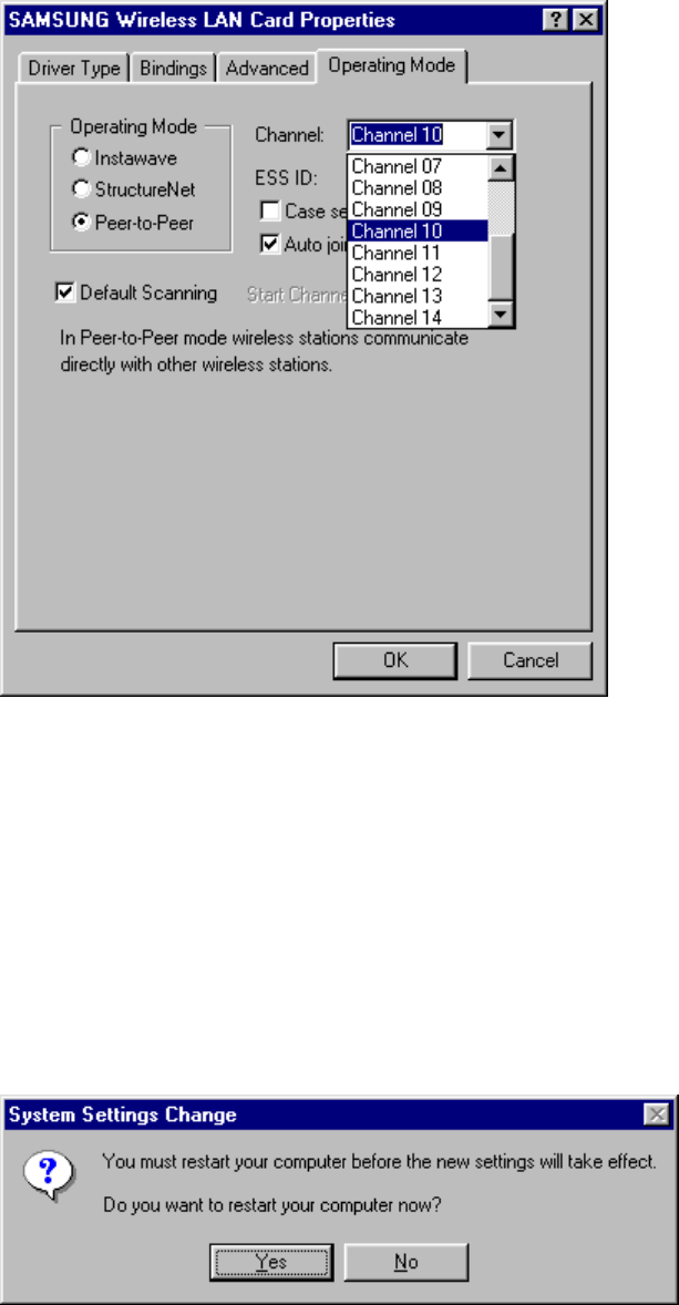
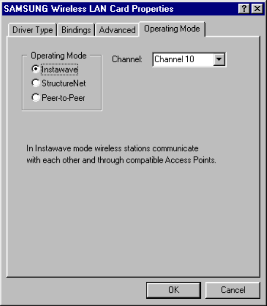
3. “Access Point Client Properties” box will appear as follow.
4. Check the Peer-to-Peer radio button in Operating Mode list.
5. Enter the desired ESS ID you are authorized to use.
(ESS ID is set to “MagicLAN” as default, but you can change it to another.)
6. Select the desired Channel you are authorized to use.
7. Change some options if you want.
8. Click on “OK” to finish up the setup.
9. “System Setting Change” box will appear as follows. Click on “No” to proceed to Network
Configuration Setup before you restart your computer.

23
3.5 Network Configuration Setup
3.5.1 Network Configuration Setup Overview
• After you finish up the hardware and software driver setup, you will need to install and configure
Microsoft Networking components.
• If you only need to access the Internet, installation of the TCP/IP networking component should be
sufficient.
• If you want some functions to share files and printers in small LAN environment, some installations may
use an alternative networking protocol called NetBEUI protocol.
• Both TCP/IP and NetBEUI protocols can be used to share files and printers between wired and wireless
computers.
3.5.2 Before TCP/IP Networking Configuration Setup
3.5.2.1 What you should know before Configuration
• TCP/IP protocol is a protocol used to connect to a Wide Area Network (WAN), such as the Internet or
hard-wired Ethernet networks.
• Every computer connecting to WAN has a unique number called IP address, which consists of two parts,
network part and host part. For example, consider the IP address 150.205.30.9.
Assuming this is part of a Class B network, the first two numbers (150.205) represent the network address
and the second two numbers (30.9) represent the host address.
• Network administrator can divide the host part of IP address into two or more subnets for more effective
use. In that case, subnet mask is used to determine what kind of subnet the IP address belongs to.
• You should consult your network administrator or Internet Service Provider (ISP) to find out your IP
address and subnet mask.
• There are two ways of obtaining an IP address. Some networks use Dynamic Host Configuration
Protocol (DHCP) to dynamically assign an IP address every time you log on to the network. Others use
static IP that is uniquely assigned to your computer and you use the same IP address whenever you log on to
the network.

24
• You should consult your network administrator or Internet Service Provider (ISP) to find out if you would
use DHCP or static IP.
• Windows Internet Name Service (WINS) is a network service that resolves a computer NETBIOS name
to an IP address. It is similar in concept to the Domain Name Service (DNS) except WINS resolves
NETBIOS names while DNS resolves host names.
• If you use a static IP and want to enable WINS, You should consult your network administrator or Internet
Service Provider (ISP) to find out the WINS server IP Address and Scope ID.
• Gateway is a hardware or software set-up that translates between two dissimilar protocols. More easily, it
can also be called a specific point to access another system. So if you want to reach out to Internet from your
PC, you should set up a gateway to pass through.
• You should consult your network administrator or Internet Service Provider (ISP) to find out your
Gateway Address.
• Domain Name Service (DNS) is the service that performs a mapping between domain names – more
English-like names - and their corresponding IP address.
• DNS can be either enabled or disabled. If you want to enable it, you should also consult your network
administrator or Internet Service Provider (ISP) to find out your Host ID, Domain, DNS Server IP
Address, and Domain suffix.
3.5.2.2 What you should have in your hands to proceed further
• Whether you would use DHCP or static IP (Required)
• Your Gateway Address (Required)
• Your IP address and subnet mask. (If you want to use static IP)
• WINS server IP Address and Scope ID (If you want to enable WINS using static IP)
• Your Host ID, Domain, DNS Server IP Address, and Domain suffix
(If you want to use DNS)
(Consult your network administrator or ISP if you are not sure any of the above, and make sure you are ready
with all the information necessary to proceed more.)
25
3.5.3 Setting Network Properties for “StructureNet” mode
1. Do the step 1 and 2 mentioned in the previous section. (Section 3.4.2)
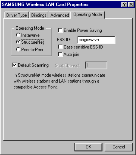
2. In “Access Point Client Properties” box, check the StructureNet radio button in
Operating Mode list.
3. Enter the desired ESS ID for the Access Point you are authorized to use.
(ESS ID is set to “magicwave” as default, but you can change it to another.)
4. Change some options if you want.
5. Click on “OK” to finish up the setup.
6. Do the step 9 mentioned in the previous section (Section 3.4.2) to make the change effective.
26
3.5.4. Setting Network Properties for “Instawave” mode
1. Do the step 1 and 2 mentioned in the section 3.4.2.
2. In “Access Point Client Properties” box, check the Instawave radio button in
Operating Mode list.
3. Select the desired Channel you are authorized to use.
4. Click on “OK” to finish up the setup.
5. Do the step 9 mentioned in the section 3.4.2 to make the change effective.
27
3.5.5 TCP/IP Networking Configuration Setup
3.5.5.1 TCP/IP Installation
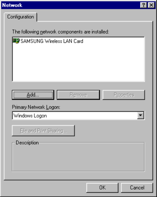
1. Right click on the Network Neighborhood icon and select “Properties” at the bottom
“Network” box may appear as follows. If you find TCP/IP in the list of Configuration
tab, skip to 3.5.5.2 (TCP/IP Properties Setup). To add TCP/IP, Click on “Add”.
28
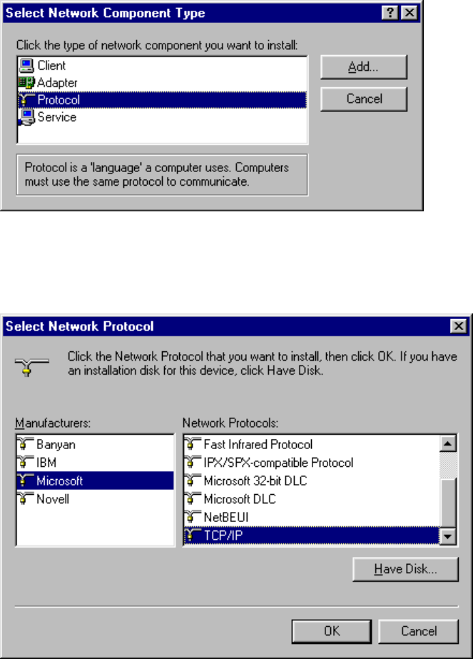
2. When “Select Network Component Type” box appears, select “Protocol” since TCP/IP
that we want to install is a Protocol. Click on “Add”.
3. "Select Network Protocol" box will appear. From the list of Manufacturers, select
"Microsoft". From the list of Network Protocols list, select "TCP/IP". Click on "OK".
29
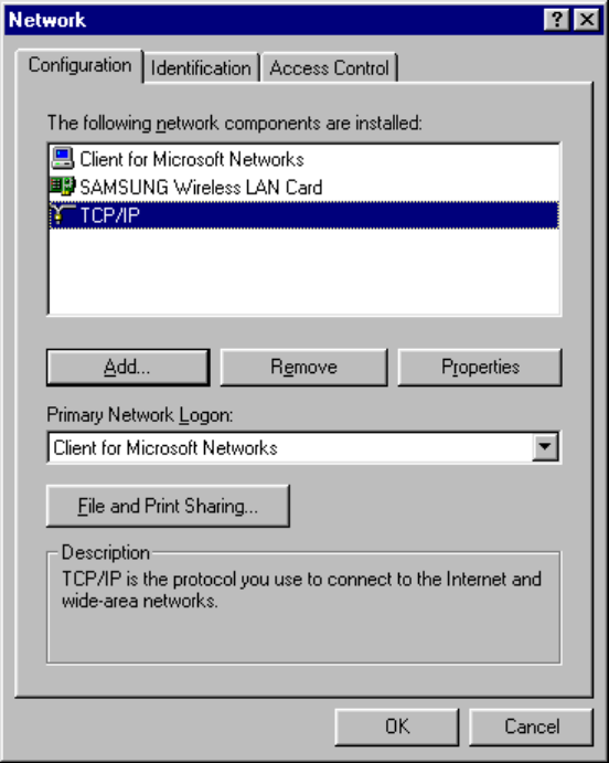
4. In “Network” box, you will see “TCP/IP”, which means that TCP/IP is successfully installed
in your system now.
5. While TCP/IP is selected, click on “Properties” to proceed for TCP/IP Properties Setup.
30
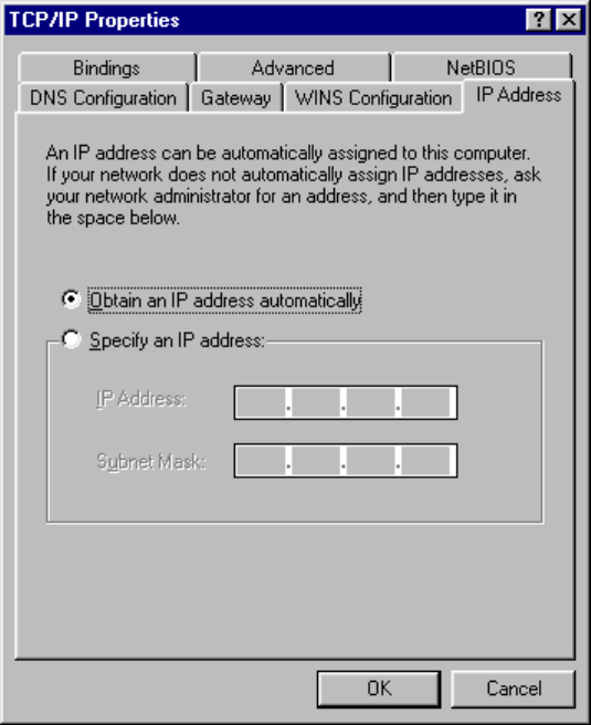
3.5.5.2 TCP/IP Properties Setup
1. Continuing from the last step, “TCP/IP Properties” box will appear. If not already selected,
select IP Address tab on top of the box to display the IP configuration setting. If you find from your
network administrator or ISP that you would use DHCP so that you can get a dynamic IP every time you
log on the network, select “Obtain an IP address automatically” and proceed to step 2a. If you use a
static IP address, select “Specify an IP address” and type in your IP Address and Subnet Mask in the
blank below, and proceed to step 2b.
Go to WINS Configuration tab on top of the box to proceed.
31
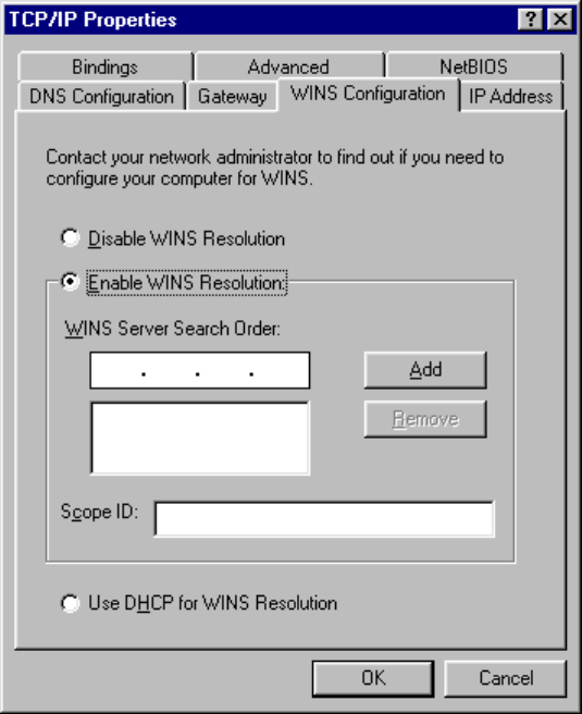
2. WINS Configuration box will appear as follows.
2a. If you use DHCP so that you would get a dynamic IP address every time you log on:
Select “Use DHCP for WINS Resolution” at the bottom.
2b. If you use a static IP address and want to:
a. Disable WINS Resolution: Select “Disable WINS Resolution” in the middle.
b. Enable WINS Resolution: Select “Enable WINS Resolution” and fill out the blanks
for WINS Server Search Order and Scope ID using the
information from your network administrator or ISP.
Go to Gateway tab on top of the box to proceed.
32
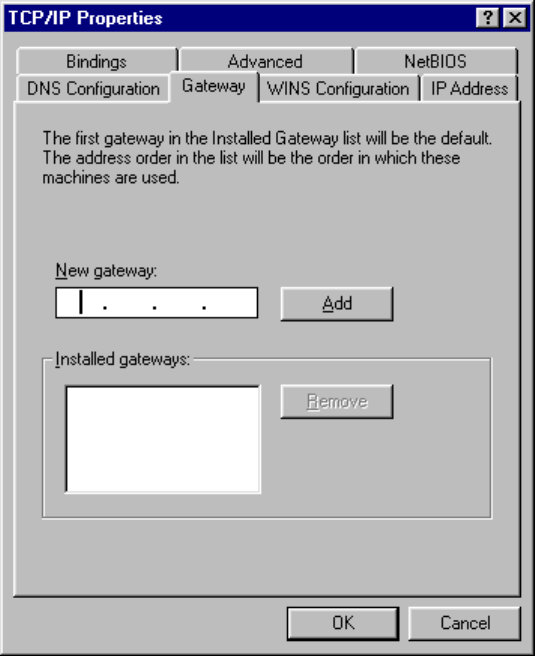
3. Gateway box will appear on your screen as follows. If your network administrator or ISP
provided you with a Gateway IP address, type that address into the “New Gateway” field and
click on “Add”. If more than one IP addresses were provided to you, repeat the procedure
until you type in all those numbers.
Go to DNS Configuration tab of top of the box to proceed.
33
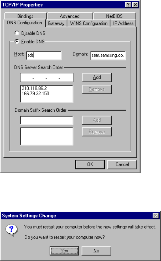
4. DNS Configuration box will appear as follows. If you want to disable DNS, check on the
radio button for “Disable DNS”. Otherwise, check on the radio button for “Enable DNS” and
type Host and Domain in the proper field. After that, type IP Address of DNS server in “DNS
Server Search Order” box and click on “Add”. Repeat this procedures if multiple IP address
of the DNS server were provided. If applicable, fill out the “Domain Suffix Search Order”
field. Click on “OK” at the bottom of “TCP/IP Properties” box.
5. “System Setting Change” box will appear as follows. Click on “Yes” to restart your
computer so that the whole installation procedures take effects.
34
4. MagicLAN Installation for Windows NT
4.1 Hardware Installation
Hardware installation procedure for Windows NT is exactly same as the one for Windows 95/98.
Please make a reference of the Windows 95/98 hardware installation section. (Section 3.1)
4.2 Software Installation
4.2.1 When there is no Windows NT Networking installed yet
1. Unlike Windows 95/98, since Windows NT does not support Plug and Play (PnP), you should
add your driver manually. To do so, click on “start” in task bar, go to “Settings”, and go to “Control
Panel”.
2. Under “Control Panel”, double click on Network icon.
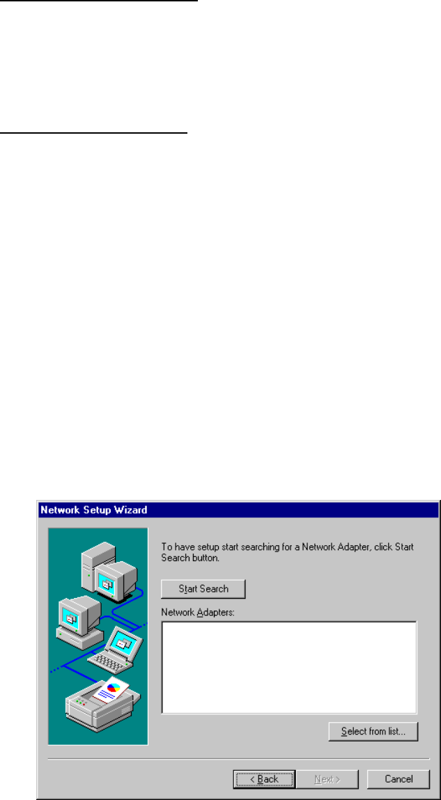
3. Since there is no NT networking installed in your system, you may be asked if you want to install NT
networking first. Click on “Yes” button. Next, you may be asked to specify how you access to the network:
modem or LAN. Check the proper selection and click on “Next”. In “Network Setup Wizard” box, click
on “Select from list” button.
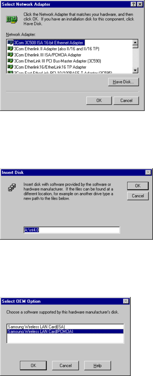
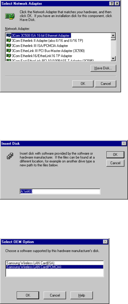
4. In “Select Network Adapter” box, click on “Have Disk” button.
35
5. In “Insert Disk” box, you may be asked to specify the necessary software directory. Insert the MagicLAN
installation disk into the floppy disk drive, type in “A:\nt4.0” in the blank and click on “OK” button. (In
this example, we assume we are installing Windows NT version 4.0.)
6. In “Select OEM Option” box, two adapters found may appear in the list. Select the proper adapter and
click on “OK” button. Usually you can select PCMCIA for laptop. In the next box, make sure that
SAMSUNG Wireless LAN Card is checked and click on “Next”.
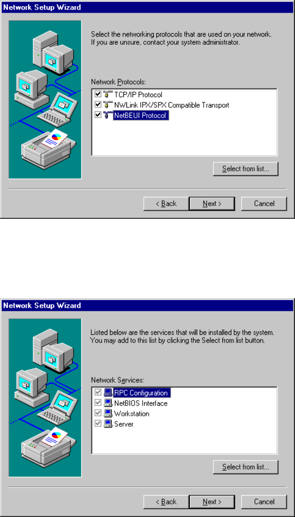
7. In the next box to choose protocols to use, make sure that all the protocols you want to use are checked
and click on “Next”.
36
8. In the next box to choose network services to use, make sure that all the services you want to use are
checked and click on “Next”.
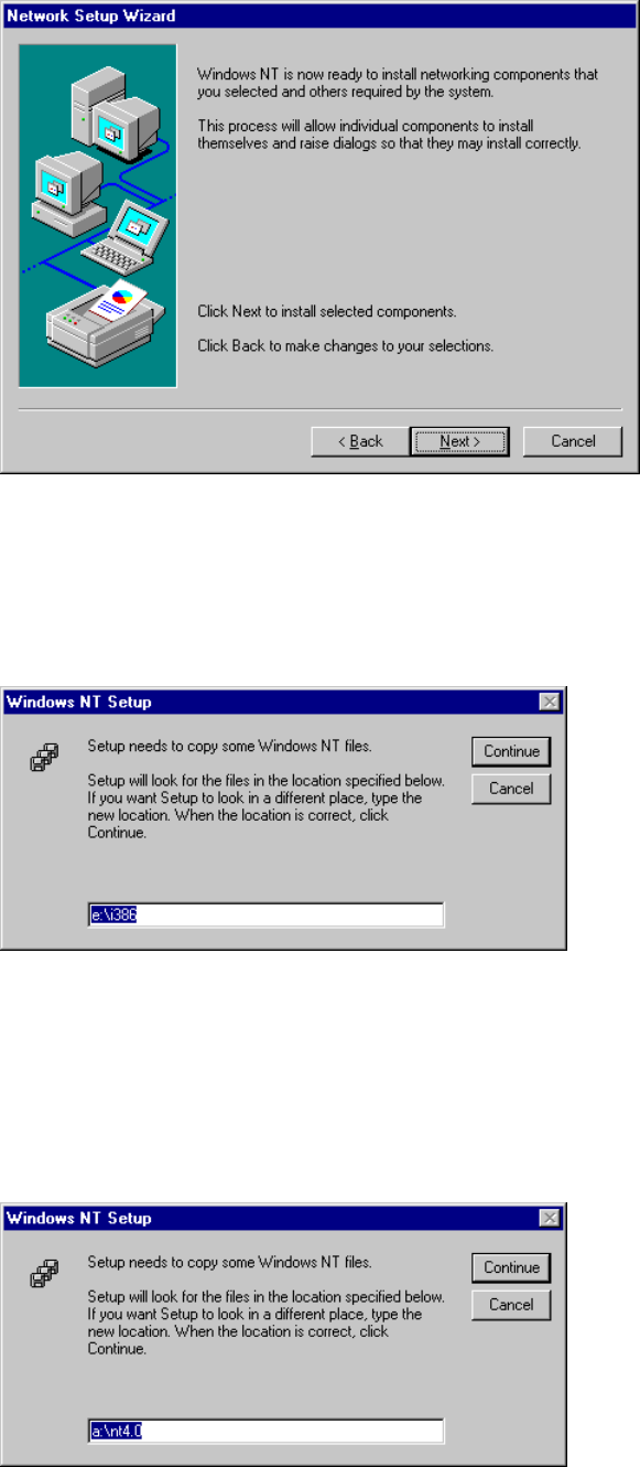
9. In the next box, it is confirmed that necessary NT networking components are selected. Click on “Next”.
37
10. When you are asked to specify the directory that the necessary NT files are copied from, insert
your Windows NT CD and type in “e:\i386” in the location blank. (Here it is assumed that the CD-ROM
drive is e drive)
11. Some files from the “e:\i386” directory are copied and you may be prompted the same box to ask
you to specify where the NT files are once more. Since it is looking for some files from the installation
diskette this time, insert your installation disk into floppy disk drive and type in “a:\nt4.0” in the location
blank. Windows NT networking is successfully installed now
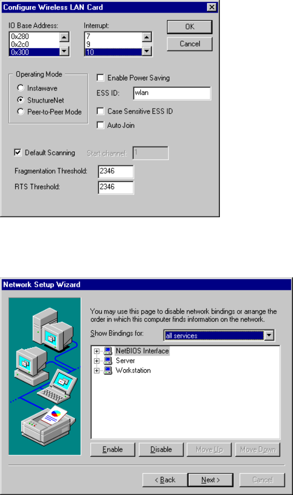
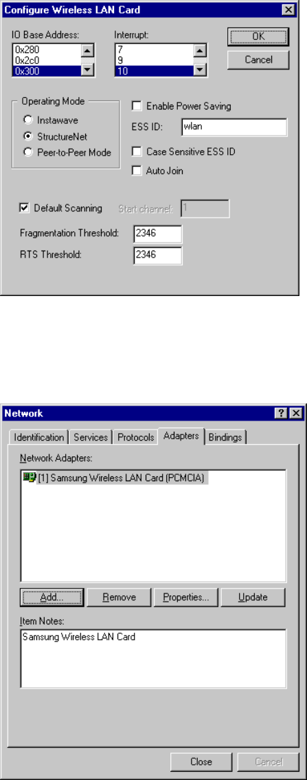
12. “Configure Wireless LAN Card” box may appear as follows. Set each some parameters (I/O
38
Base,
Interrupt, Fragmentation Threshold, RTS Threshold) for the proper system configuration setup and other
parameters (Operating Mode, ESS ID, etc.) for the proper LAN Card configuration setup. For the
information on LAN Card-related parameters, you can refer to the explanation on the previous section
(3.4 SAMSUNG Wireless LAN Card Properties Setup). If you are not sure any of system configuration-
related parameters, please refer to your network administrator. After you set all the parameters necessary,
click on “OK” to proceed.
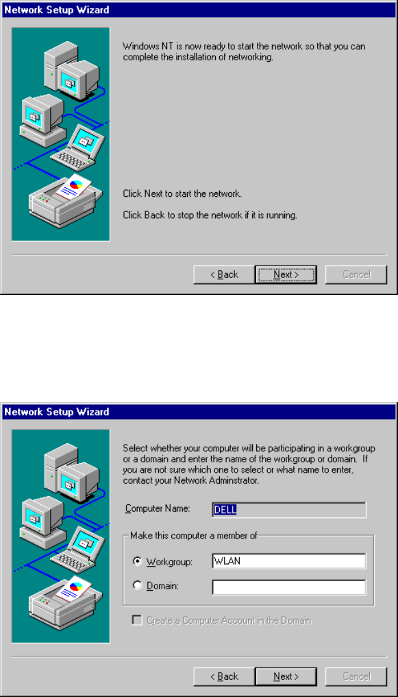
13. Network binding related box may appear next. Click on “Next” to proceed.
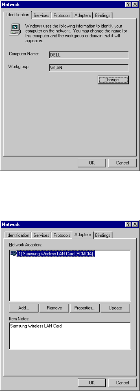
14. Next box will say network installation is done and network is ready to start. Click on “Next” in
that box and “Finish” on the next box to start network.
39
15. You will be prompted to enter the name of the Workgroup or Domain in the next box. Type in a
desired name of it and click on “Next” to proceed.
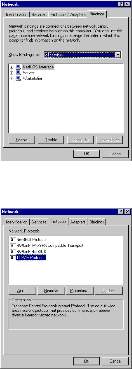
16. “Network” box with Identification tab selected will appear as follows. You can change the
Computer Name and Workgroup after clicking on “Change” in the middle of the box.
40
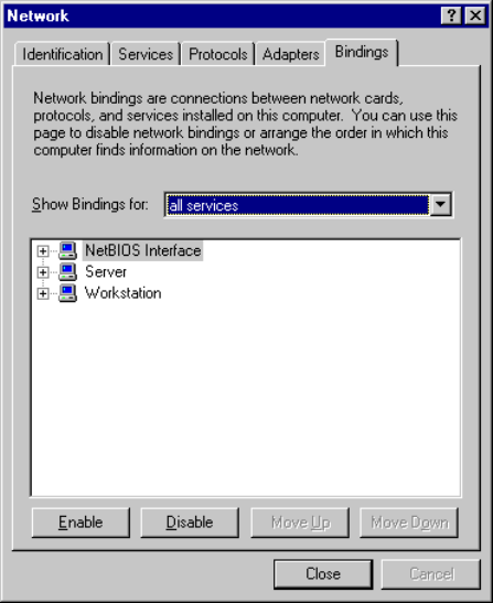
17. Go to Adapters tab of the “Network” box, and make sure that “SAMSUNG Wireless LAN
Card” are installed and currently selected.
18. Go to Binding tab of the “Network” box and check if all the necessary services are binded.
41
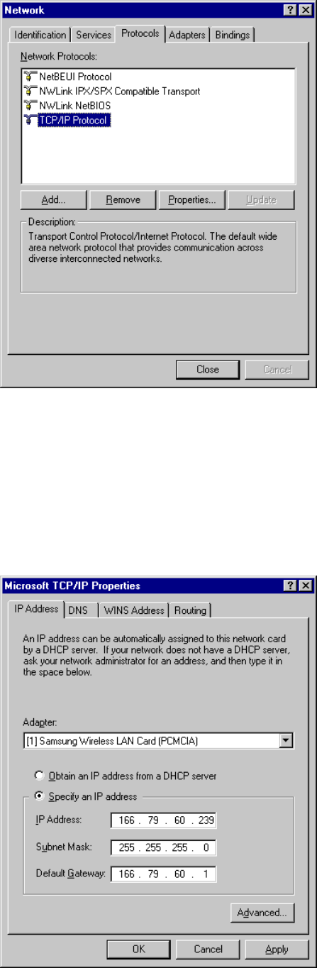
19. Go to Protocols tab of the “Network” box. Select “TCP/IP Protocol” in the list and click on
“Properties” button.
20. “Microsoft TCP/IP Properties” box with IP Address tab selected will appear as follows. Select
“SAMSUNG Wireless LAN Card” in the Adapter section, and fill out the rest sections with proper
information. About the parameters and meaning, you can refer to the explanation in the previous section.
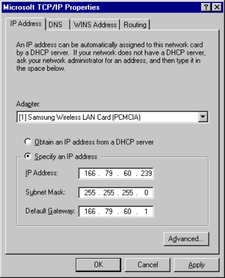
42
(3.5 Network Configuration Setup). If you are not sure about any of the required information in this
section, please consult to your network administrator. Go to DNS tab.
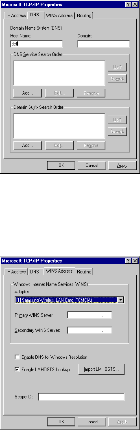
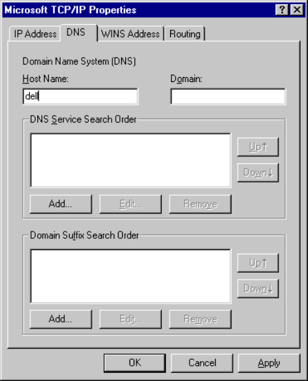
21. In “Microsoft TCP/IP Properties” box with DNS tab selected, enter the proper information for
the blanks. About the parameters and meaning, you can refer to the explanation in the previous section.
(3.5 Network Configuration Setup). If you are not sure about any of the required information in this
section,
please consult to your network administrator. Go to WINS Address tab.
43
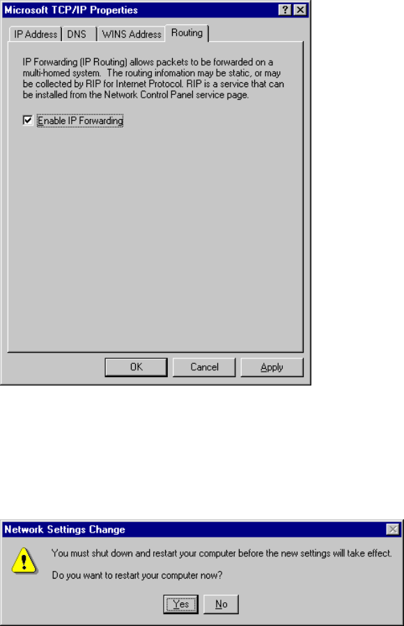
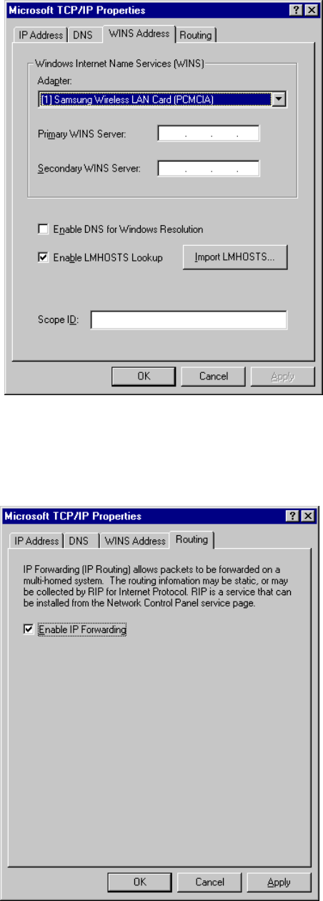
22. In “Microsoft TCP/IP Properties” box with WINS Address tab selected, select SAMSUNG
Wireless LAN Card (PCMCIA) and fill the rest of the blanks with the proper information. About the
parameters and meaning, you can refer to the explanation in the previous section. (3.5 Network
Configuration Setup). If you are not sure about any of the required information in this section, please
consult to your network administrator. Go to Routing tab.
44
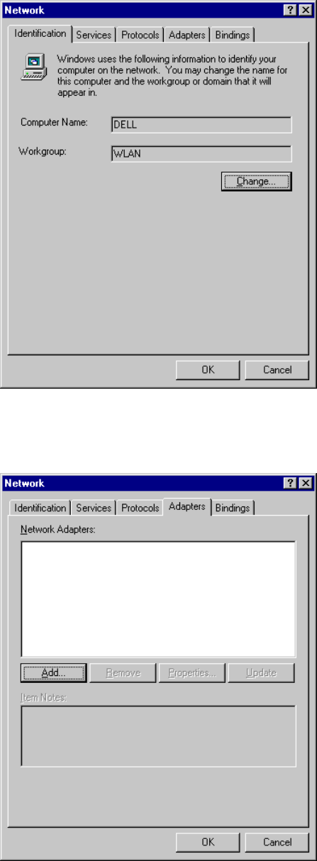
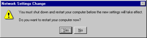
23. In “Microsoft TCP/IP Properties” box with Routing tab selected, make sure if “Use IP
Routing” is checked only if you want NT to play a role of router in your network. Click on “OK”.
24. When TCP/IP properties are set, click on “Close”. Then “System Setting Change” box will
appear as follows. Click on “Yes” to restart your computer so that the whole installation procedures take
effects.
4.2.2 When There is Windows NT networking already installed
1. Unlike Windows 95/98, since Windows NT does not support Plug and Play (PnP), you should
add your driver manually. To do so, click on “start” in task bar, go to “Settings”, and go to “Control
Panel”.
2. Under “Control Panel”, double click on Network icon.
45
3. “Network” box with Identification tab selected may appear as follows. You can change the Computer
Name and Workgroup after clicking on “Change” in the middle of the box.
4. Go to Adapters tab of the “Network” box, and click on “Add” button in the middle.
46
5. “Select Network Adapter” box may appear as follows. Click on “Have Disk”.
6. “Insert Disk” box may appear as follows. Insert the Installation Diskette into your floppy drive and
specify the path “A:\nt4.0” in blank field. Click on “OK”. (In this example, we assume we are installing
Windows NT version 4.0.)
7. If the Driver is successfully set up, “Select OEM Option” box may appear. Select the card type. Usually
you can select PCMCIA for laptop. Click on “OK”.
8. “Configure Wireless LAN Card” box may appear as follows. Set each some parameters (I/O Base,
47
Interrupt, Fragmentation Threshold, RTS Threshold) for the proper system configuration setup and other
parameters (Operating Mode, ESS ID, etc.) for the proper LAN Card configuration setup. For the
information on LAN Card-related parameters, you can refer to the explanation on the previous section
(3.4 SAMSUNG Wireless LAN Card Properties Setup). If you are not sure any of system configuration-
related parameters, please refer to your network administrator. After you set all the parameters necessary,
click on “OK” to proceed.
9. “Network” box with Adapters tab selected may appear as follows. Make sure “SAMSUNG Wireless
LAN Card” is installed and currently selected.
48
10. Go to Binding tab of the “Network” box. Make sure that all the necessary services are binded.
11. Go to Protocols tab in the “Network” box. If you have TCP/IP protocol already installed in your
system, select “TCP/IP Protocol” and click on “Properties”. If you do not have TCP/IP protocol installed
yet, you will have to add it by clicking on “Add” button, selecting “TCP/IP Protocol”, and clicking on
“OK”. Once you add it, click on “Properties”.
49
12. “Microsoft TCP/IP Properties” box with IP Address tab selected will appear as follows. Select
“SAMSUNG Wireless LAN Card” in the Adapters section, and fill out the rest sections with proper
information. About the parameters and meaning, you can refer to the explanation in the previous section.
(3.5 Network Configuration Setup). If you are not sure about any of the required information in this
section, please consult to your network administrator. Go to DNS tab.
50
13. In “Microsoft TCP/IP Properties” box with DNS tab selected, enter the proper information for
the blanks. About the parameters and meaning, you can refer to the explanation in the previous section.
(3.5 Network Configuration Setup). If you are not sure about any of the required information in this
section,
please consult to your network administrator. Go to WINS Address tab.
14. In “Microsoft TCP/IP Properties” box with WINS Address tab selected, select “SAMSUNG
Wireless LAN Card” and fill the rest of the blanks with the proper information. About the parameters
and meaning, you can refer to the explanation in the previous section. (3.5 Network Configuration Setup).
If you are not sure about any of the required information in this section, please consult to your network
administrator. Go to Routing tab.
51
15. In “Microsoft TCP/IP Properties” box with Routing tab selected, make sure that “Enable IP
Forwarding” is checked only if you want NT to play a role of router in your network. Click on “OK”.
16. When TCP/IP properties are set, click on “Close”. Then “System Setting Change” box will
appear as follows. Click on “Yes” to restart your computer so that the whole installation procedures take
52
effects.
53
5. Packet Driver Installation for MS-DOS
5.1 Copy the Packet Driver
1. Create a new directory where you want to store a Packet Driver software on your hard disk.
Ex> c:\>md packet
(From this point, directory “Packet” right under root directory will be used for packet driver
software directory for clearer explanation.)
2. Insert the installation diskette in drive A.
3. Copy all files in 'a:\dos>' to the ‘c:\Packet>’ directory which you created in the step 1.
Ex> a:\dos>copy *.* c:\packet
5.2 Setup AUTOEXEC.BAT
1. Change current directory to c:\
2. Open 'AUTOEXEC.BAT' with any text editor such as edit.exe
Ex> c:\>edit autoexec.bat
3. Add the following line at the last line of ‘AUTOEXEC.BAT’ file.
Ex> c:\packet\magicwav.exe
4. Save 'AUTOEXEC.BAT' and exit the editor program.
5.3 Setup MAGICWAV.CFG
1. Change current directory to “Packet” directory right under root(C:\) directory.
2. Open 'MAGICWAV.CFG' using a text editor such as edit.exe.
Ex> edit MagicWave.cfg
3. The structure of the 'MAGICWAV.CFG' is as follows.
a. Basic Parameters that should be set:
ESSID: MAGICWAVE (default)
NETWORKMODE: 1 (default)
CHANNEL: 3 (default)
INTEROP: 1 (default)
b. Parameters for Users that the driver will ignore:
(If you do not want to use PNP, set these parameters.)
IRQ: 9 (default)
IO: 240 (default)
MEM: D800 (default)
54
4. To set a parameter value, type in parameter name and a value within the range as specified in
Table A.
5. Save 'MAGICWAV.CFG' and exit editor program.
6. If you want to use TCP/IP protocol, you should load TCP/IP driver after loading packet driver.
To do this, you must refer to the TCP/IP driver manual.

55
Table A. MagicLAN Packet Driver Parameter Values
Parameter Description
ESSID Alphanumeric string with a maximum of 10 ASCII
characters that identifies the network to which you would
like to connect your computer.
Note that this string is NOT case-sensitive.
NETWORKMODE MagicLAN can be used in 'Ad-Hoc' mode where Access
Point (AP) is not required or in 'Infrastructure' mode where
all communication will be made through an AP.
Available values are as follows:
0 : Ad-Hoc mode
1 : Infrastructure mode
CHANNEL This parameter is used as an operating channel.
The domain and its available channel are shown in Table
B.
INTEROP Interoperability Flag. If this parameter set to '1',
MAGICLAN can be used with other wireless LAN cards
that based on IEEE 802.11 specification and support
interoperability. Otherwise MAGICLAN can communicate
only with MAGICLAN LAN card.
IRQ Interrupt Request Number. If you use PnP (Plug and Play)
bios, you can leave this parameter unspecified.
Available values are as follows:
PCMCIA cards : 2 to F
IO This parameter is used as an I/O base port for
MAGICLAN. If you use PnP (Plug and Play) bios, you can
leave this parameter unspecified.
Available values are as follows:
200, 240, 280, 2C0, 300, 340, 380
MEM This parameter is used as a memory base address segment
for MAGICLAN. If you use PnP (Plug and Play) bios, you
can leave this parameter unspecified.
Available values are as follows:
C800, D000, D800

56
Table B. Number of operation channels
Frequency FCC USA Canada
(ETSI)
Europe Spain
(MKK)
Japan
12412 MHz OOO
22417 MHz OOO
32422 MHz OOO
42427 MHz OOO
52432 MHz OOO
62437 MHz OOO
72442 MHz OOO
82447 MHz OOO
92452 MHz OOO
10 2457 MHz OOOOO
11 2462 MHz OOOOO
12 2467 MHz O O
13 2472 MHz O O
14 2484 MHz O
For each supported country, all channels in Table B marked with 'O' shall be supported.

57
6. Access Point (AP) Installation
6.1 Before Access Point (AP) Installation
6.1.1 Access Point (AP)
SAMSUNG MagicLAN SWL-2000AP (Access Point) is equipped with an Ethernet Adapter supporting
10base-T, 10bast-2 LAN wire and MagicLAN wireless LAN Adapter Card.
6.1.2 What you need for the installation
SWL-2000AP (Access Point) and Power Adapter
SWL-2000N (PCMCIA Wireless LAN) Adapter Card
SWL-2000AP (Access Point) Utilities Diskette
Null Modem Cable - Optional
6.2 Access Point (AP) Installation
6.2.1 Access Point Setup using Null Modem Cable
1. Link the PC serial port and the AP serial port with Null Modem Cable.
2. Insert 10base-T or 10bast-2 LAN line to the proper slot in the back of the AP.
3. Insert the SWL-2000N into the PCMCIA slot of in the back of the AP.
4. Turn on the power of the AP
5. All the LEDs will turn on and off. If the alert LED remains on, it indicates an error condition.
6. Press down “Start” on the task bar, go to “Programs”, go to “Accessories”, go to “Communications”
and click on “Hyper Terminal” there.
7. If there is no “Hyper Terminal”, you should add Hyper Terminal program by following the next steps.
Press down “Start” on the task bar, go to “Settings” and click on “Control Panel”. In “Control Panel”
box, double click on “Add/Remove Programs”, go to Windows Setup tab, double click on
“Communications”, check the “Hyper Terminal” and click on “OK”. This will install Hyper
Terminal on your system, and now you can follow the next step.
8. Run Hyper Terminal by double clicking on Hyper Terminal icon.
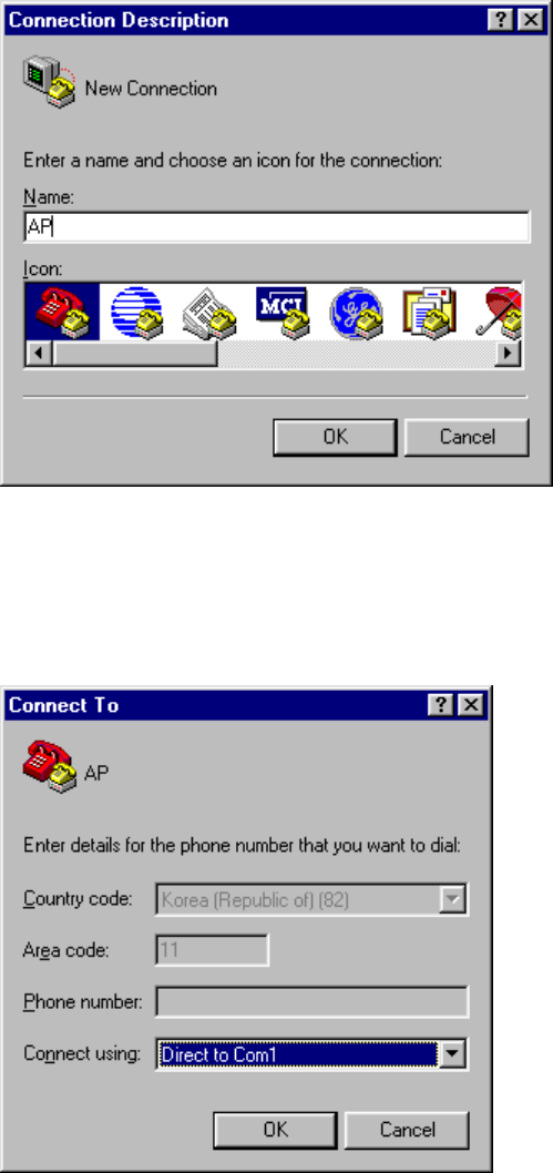
9. Enter any name for the connection in the blank and select an icon for it in the following box.
Click on “OK”.
58
10. “Connect To” box will appear as follows. Select “Direct to Com1” for “Connect using” blank.
Click on “OK”. (If error occurs, check if other communication device such as modem is using the
same port. If so, remove the port from that device and follow the step again.)
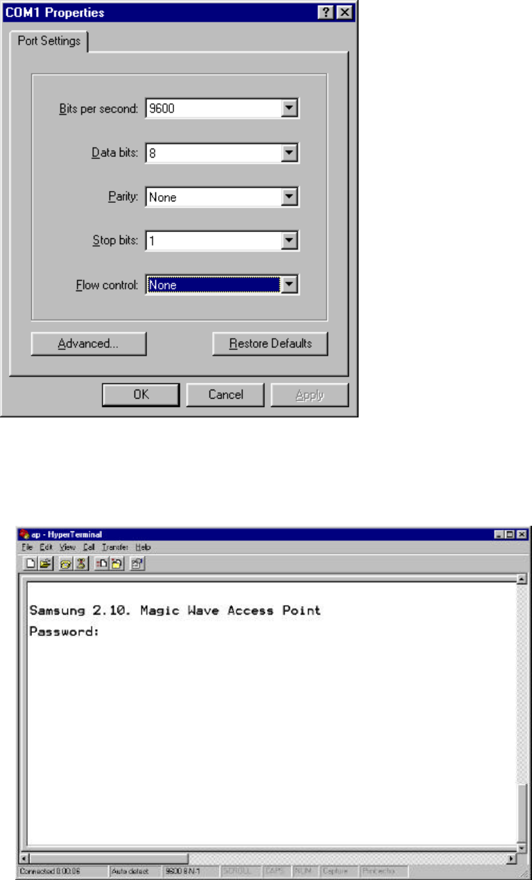
11. “Com1 Properties” box will appear as follows. Set the property value as follows:
Bits per second = 9600, Data bits = 8, Parity = None, Stop bits = 1 and Flow control = None.
Click on “OK”.
59
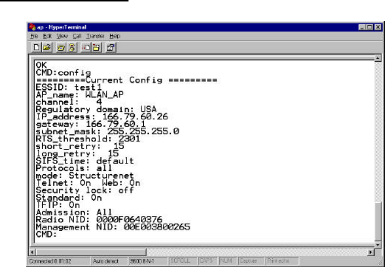
12. “Hyper Terminal” box will appear to show your the connection to AP as follows. When you are
prompted to enter a Password, type in “default” which is a preset default password.
60
6.2.2 Access Point Setup without Null Modem Cable (Cold Start Mode)
1. Insert 10base-T or 10bast-2 LAN line to the proper slot in the back of the AP.
2. Insert the SWL-2000N into the PCMCIA slot of in the back of the AP.
3. Turn on the power of the AP WHILE you are holding down the button in front of the AP.
4. All the LEDs will turn on and off. When all the LEDs are off, release the button, and you will see
all the LEDs blinking in a chasing pattern from left to right.
5. Now, from your wired PC (not wireless), go to “start” in your task bar, go to “run”, and type in “ping –t
xxx.xxx.xxx.xxx” to send ping message to your AP. (Here, xxx.xxx.xxx.xxx represents an IP address you
want to assign to your AP)
6. When your AP responds to this ping request, the blinking of your AP will stop.
7. Turn off the power of your AP and turn it back on with no button pressed down this time.
8. From your PC, telnet to your AP using its IP address and proceed to the configuration setup.
9. When you are prompted to enter a Password in telnet mode, type in “default” which is a preset default
password.
6.3 Configuration Setup
1. To get help about commands, just type in “help” at CMD prompt.
2. In order to identify the CONFIGURATION, you type in “config” at CMD prompt and press the ENTER
key.
3. Set parameters for the environment using the “set” command at CMD prompt as follows:
CMD: set ESSID MagicLAN (Group Name)

61
CMD: set AP_name WLAN_AP (Access Point Name)
CMD: set channel 1 (RF channel)
CMD: set IP_address 123.45.67.8 (origin IP of the AP)
CMD: set gateway 123.45.67.1
CMD: set mode structurenet
CMD: set Telnet on/off (for telnet connection)
CMD: set Web on/off (for http connection)
CMD: set standard on (for interoperability)
4. After you set all the parameters for your system, execute “restart” command to make the changes
take effects.
5. Now your AP is ready to be used.
6.4 Parameter Setup
• RADIO RELATED
channel: This field specifies the operating channel for the SWL-2000AP. The SWL-2000AP allows from 1
to 13 but the channels used by adjacent AP should be apart by more than 5 channels. For example, if an AP
uses channel 1, the adjacent AP should use channel 6 or higher for the best output.
Default: 1
RTS_threshold: This field determines the size of RTS(Request-To-Send)/CTS(Clear-To-Send) frames and
the frames to be used.
Default: 2301
short_retry: This field specifies the number of transmissions of RTS/CTS to be attempted before aborting
when the communication between clients is interfered. Note that RTS/CTS are delivered back and forth
between the clients to monitor the channel for the possibility of communications.
Default: 15
long_retry: This field specifies the number of trials of data transmission when the channel or a client causes
the cease of data transmissions.
Default: 15
Standard: This field is used for interoperability between multiple IEEE 802.11 venders.
Default: on
62
• ACCESS POINT FEATURES
essid: This field is used to name a wireless LAN group when in StructureNet mode. If the roaming is to be
supported, the value of ESS_ID of all the APs should be the same.
Default: wlan
ap_name: This field is a string up to 9 letters and is used to give SWL-2000AP an identifier name. This is
useful if you have multiple APs on a network for roaming. In that case the essid for all APs should be same
but ap_name for each AP should be different.
Default: LocalAP
mode: This field specifies the operating mode of the unit. Insert the “Instawave” for <Peer-to-Peer> and the
“StructureNet” for <StrectureNet>.
Default: StructureNet
protocol: The normal mode of an AP is to pass all protocols. In this case the value of default protocol should
be “all”. If your wireless station uses TCP/IP protocol only, you can set the value of protocols to “TCP/IP”.
In this case, non TCP/IP messages are not passed by the AP.
Default: All
• TCP/IP PARAMETERS
IP_address: This field is used to assign a TCP/IP address to the AP and needed when a user manages the AP
by TELNET or uses web manager utilities. A user can access management utilities for the AP by putting in
the assigned IP address on TELNET or WEB BROWSER.
Default: 0.0.0.0 (No IP address assigned)
subnet_mask: This field is used to define the TCP/IP sub-net mask. This field should be set if you plan to
use the built in management features of the AP.
Default: 255.255.255.0
gateway: This field is needed to connect to an external network using the TCP/IP protocol. SWL-2000AP
stores all the IP addresses received from TCP/IP ARP (Address Resolution Protocol) message. If the
destination is an IP address instead of a local network, the packets are sent to a gateway.
Default: 0.0.0.0 (no gateway)
• MANAGEMENT FUNCTIONS
password: This field allows the manager to define the password used by the Command Line Manager before
they can enter commands.
Default: “default”
telnet: This field enables or disables the built TELNET management capability. This field will not affect a
terminal attached via the serial port, which is always enabled when a terminal is attached. You can select
either “on” or “off” to enable or disable it.
Default: on

63
web: This field enables or disables the built in web management utility. You can select either “on” or “off”
to enable or disable it.
Default: “on”
6.5 Null Modem Cable Configuration
9 pin female connector 9 pin female connector
pin 5 <==============> pin 5 < Ground - Ground >
pin 3 <==============> pin 2 < Transmit - Receive >
pin 7 <==============> pin 8 < RTS - CTS >
pin 6 <==============> pin 4 < DSR - DTR >
pin 2 <==============> pin 3 < Receive - Transmit >
pin 8 <==============> pin 7 < CTS - RTS >
pin 4 <==============> pin 6 < DTR - DSR >
6.6 Diagnostic Methods
1. When the “power” LED of the Access Point does not illuminate, make sure that the power cord is fully
seated in the socket on the rear panel of the unit.
2. When the “alert” LED continuously illuminates or blinks, check the states of the radio card (SWL
-1000N) installed in the Access Point. Unplug and re-plug POWER (OFF/ON again).
3. If the “alert” LED continuously illuminates or blinks, please contact your local service center or the
retailer
where you purchased the units.

64
7. Management Utilities (Web & Telnet)
7.1 About Management Utilities
SAMSUNG MagicLAN has three ways of managing the configuration setup for SWL-2000AP: through
Hyper Terminal, Web and Telnet service. Using one of those three, you can change the initial setup for AP
that you were supposed to do at the previous chapter. (6. Access Point Installation)
7.2 Hyper Terminal Management Utility
You can use Hyper Terminal to manage the AP configuration setting by doing the same step as explained at
the previous chapter. (6. Access Point Installation)
Remember that you will need a null modem cable to use Hyper Terminal.
7.3 Web Management Utility
7.3.1 Web Management Utility Overview
In order to view the web management page, start your web browser and simply enter the IP address of your
Access Point in the “address” or “URL” field. On most browsers, the screen will refresh with the latest
information every 10 seconds. With IE4.0 you can stop the auto refresh by clicking on the “Stop” button of
the browser. The followings are some of the Web Management Utility pages.
• Status Report
• Statistics
• Configuration Settings
• Bridge Table Report
65
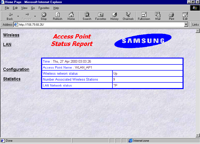
7.3.2 AP Status Report (http://xxx.xxx.xxx.xxx)
This page provides the basic information on wireless network setup including AP.
•• Time: The current time as set in the SWL-2000AP
•• Access Point Name: The “AP_name” parameter of the SWL-2000AP.
•• Wireless Network Status: If the AP is operating normally the field will show “Up”. If there is
any problem with the AP, or no AP installed, the field will show “Down”.
•• Number Associated Wireless Stations: This shows how many wireless clients are currently
connected to the AP.
•• LAN Network status: This field will show “TP” when the Twisted Pair (10baseT) connection
is operating. Otherwise it will show “Coax”.
66
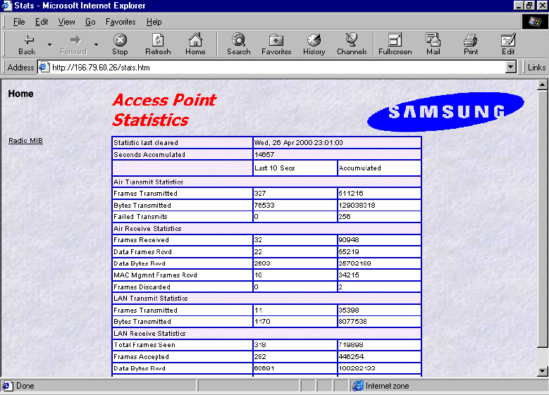
7.3.3 AP Statistics (http://xxx.xxx.xxx.xxx/stats.htm)
This page provides statistical information on the AP and radio functions. It shows accumulated traffic
information. There are two columns shown in the table: “last 10 seconds” and “accumulated”. Columns
under “last 10 seconds” will represent the data during the last 10 seconds, and columns under
“accumulated” will represent the accumulated data till then. The whole screen will be automatically updated
every 10 seconds.

67
Field Name Description
Air Transmit Statistics
Frames Transmitted The count of frames transmitted on the wireless medium.
This does not count retry frames - if a frame is sent twice.
Bytes Transmitted The number of bytes contained in the frames that have been
transmitted.
Failed Transmits The number of frames which could not be transmitted.
Air Receive Statistics
Frames Received The number of frames of all types received by the Access
Point from the radio.
Data Frames Received The number of frames received from the radio which are
data frames (as opposed to management frames etc).
Data Bytes Received The number of bytes contained in the data frames received.
MAC Management Frames
Received
The number of frames received such as IEEE802.11 beacons
or association requests.
Frames Discarded The count of frames which were discarded, because of
duplicate rejection or because of buffer overflow.
LAN Transmit Statistics
Frames Transmitted The number of frames transmitted from the Access Point to
the Ethernet LAN.
Bytes Transmitted The number of bytes in the frames transmitted.
LAN Receive Statistics
Total Frame Seen The number of frames seen on the LAN
Frames Accepted The number of frames accepted by the Access Point.
Data Bytes Received The count of bytes contained in frames accepted by the AP.
Frames Discarded Frames which were discarded because of problems such as
bad CRC or buffer overflow.
68
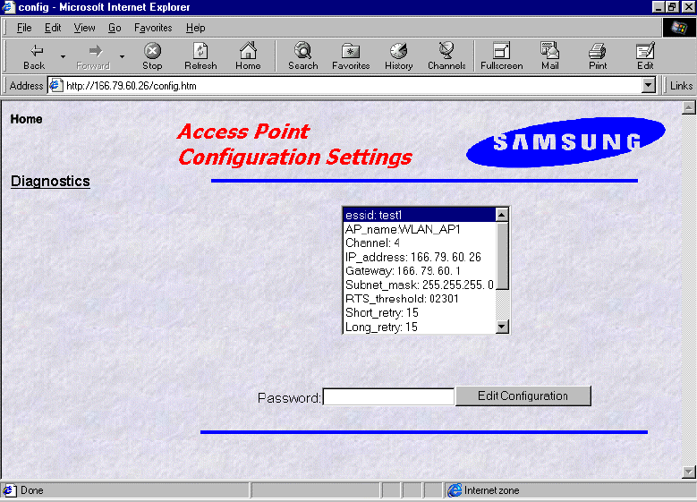
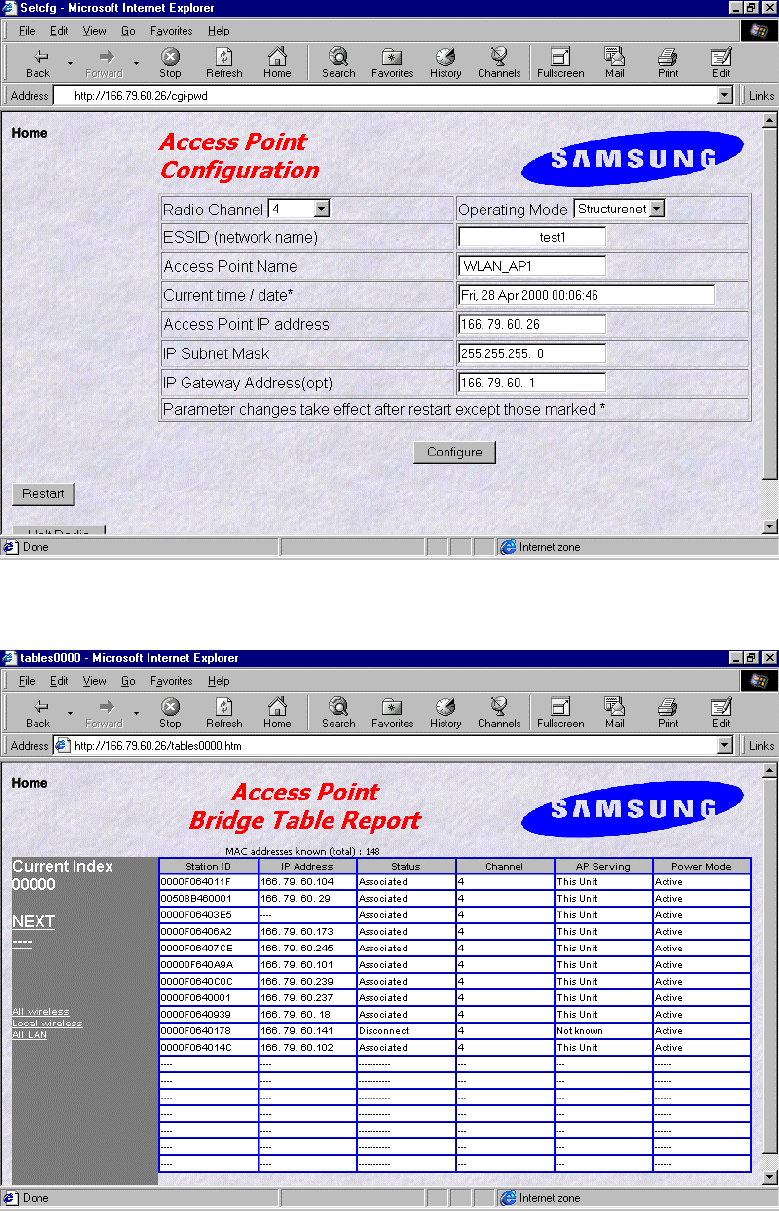
7.3.4 AP Configuration Settings (http://xxx.xxx.xxx.xxx/config.htm)
This page displays the current configuration and allows the access to the page where you can
change the configuration setup. If you want to change the configuration setup, enter the password and click
on the “Edit Configuration” button, and it will lead you to configuration setup change page like the below.
The initial password is preset to “default”.
69
7.3.5 Access Point Bridge Table Report (http://166.79.60.26/tables0000.htm)
This station screen allows the manager to see which wireless stations are currently active on the Access
Point (Wireless) and Wired LAN (LAN). The screen shows up to 18 stations at a time.
So the “NEXT” hyperlink will lead you to view the next 18 stations in the list and “PREV” hyperlink will
lead you to go back to the previous list.

70
Field Name Description
Station ID This is the NID (Network ID) or the name of the station if
set. The name is obtained from the NID name table.
IP Address The IP address of the station ( if known )
“Associated” means that the station is associated with this
Access Point.
“Disconnected” means that the station is not associated
with this AP could however, be associated with another AP.
“Detected” means that frames from the station have been
seen but, that it has not been associated.
“Bridged” entries are wired stations that are reached
through a different Access Point than the current displayed
one.
“Is Bridging” is Access Points detected over the air. These
other Access Points provide for wireless bridging between
two separate LAN segments.
Status
“Local AP” means that it is another AP on the same LAN.
This entry will be seen where roaming is implemented.
Channel The radio channel of the station.
AP Serving If the station is associated the words “This Unit” will
appear.
Otherwise the NID or name of the Access Point to which
the station is associated will be shown.
Power Mode If the station supports “Power Save Poll” mode of
IEEE802.11, this field will indicate that power saving is
active with the word “On”.
71
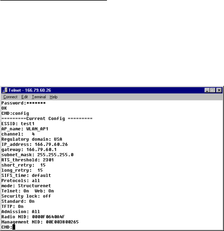
7.4 TELNET Management Utility
7.4.1 Telnet Management Utility Overview
In order to browse Telnet management setup, type the command “telnet xxx.xxx.xxx.xxx” in DOS windows
and the TELNET screen will appear as follows. Here, “xxx.xxx.xxx.xxx” represents the IP address of your
destination AP. When you are prompted to type in the password, enter “default” which is preset as a default
password.
7.4.2 Various Commands and Usage
7.4.2.1 Usage of the command line
The user can enter commands in the following form:
Command parameter1 parameter2
7.4.2.2 All possible Commands
show arp config stats
set nid bridge restart
time settime setdate ping
logout ver log help
trace traceon traceoff tracelp
traceclr broadcast disable
72
7.4.2.3 Explanation on various Commands
•• help: Displays list of all the commands.
Usage: help [command]
•• show: Displays the number of attached clients in both wireless and wired LAN.
Similar to the “Bridge Table Report” screen of the Web Management Utility.
a. Usage: show [A | G | S]
- A: List of all known clients attached via wireless LAN.
- G: List of all known clients attached via wired LAN.
- S: List of all wireless stations.
b. The result of the command is list providing the following information.
- Net ID: IEEE network address of the client.
- State: Current relationship of client with AP
(Associated, Disconnected, Detected, is bridging, bridged, Local AP, Unknown).
- Channel: Radio channel.
- Power: Whether the power of the client is on or off. (On, Off)
- Current AP: The Access Point with which the unit is associated.
- IP address: IP address of the client.
• time: Displays the current date and time and those of last restarted time.
• settime: Sets the system time.
Usage: “settime HH(hours):MM(minutes):SS(seconds)”
• setdate: Sets the system date.
Usage: “setdate MM(month):DD(date):YY(year)”
• config: Displays the current system settings for configuration. Note that if a configuration
change has been made which requires a system restart to take effect, both the old and the new
values will be shown.
• stats: Displays traffic statistics. Statistics are displayed for the last 10 second interval. To
view the cumulative total, use the command line of “stats c”.
• logout: After this command has been issued the user must re-enter the password before any
more commands can be issued.
• ver: Displays version information about the Access Point software.
• restart: Reinitializes the SWL-2000AP.
• ping: Issues an ICMP Echo request (PING) to the specified IP address.
Usage: “ping xxx.xxx.xxx.xxx [yy]”
(Here, “xxx.xxx.xxx.xxx” is the destination IP address and yy option will make this ping
command executed indefinitely.)
• nid: nid is the unique number of wireless LAN card, which is also called “MAC Address”.
Usage: “nid [add | delete] 123456789abc NAME” / “nid list”
73
(Here, “123456789abc” is the new NID value and “NAME” is a text string up to 9
characters with no space in between.)
• trace: Displays the contents of the trace buffer. This command does NOT clear the trace
buffer so that issuing the command twice will produce the same result.
• traceclr: Clears the entries which have been read by the trace command.
• tracelp: Displays a continuously updated log to the screen. To exit, press <Ctrl+C>.
Usage: “tracelp” : Updates the display every 5 seconds.
“tracelp Q”: Updates the display every second.
“tracelp S” : Updates the display every minute.
• traceon: Activates tracing for certain events. (Refer to “traceoff”)
• traceoff: Deactivates tracing for certain events.
Usage: “traceoff <specifier> <specifier>”
Here, specifier is of the following strings:
- “br+” : Traces new entries in the bridge table.
- “br-”: Traces bridge table entries which age out.
- “IP+”: Traces new TCP/IP address.
- “sys”: Traces authenticate, associate, WIN/LOSE negotiations (roaming).
- “all”: Turns off or on tracing of all events.
Default specifier Combinations are like the following:
- “traceon sys”
- “traceoff br+ br- IP+”
74
8. Miscellaneous Features
8.1 Connection Check
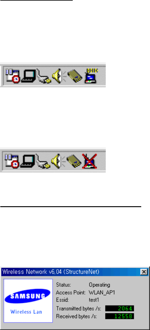
8.1.1 When successfully connected to Network through AP
On task bar at the bottom of window, you will see a monitor-like SWL-2000N icon, which is colored blue.
The icon looks like the following. (The rightmost one)
8.1.2 When failed to connect to Network through AP
On task bar at the bottom of window, you will see a monitor-like SWL-2000N icon with “red X” through it.
The icon looks like the following. (The rightmost one)
8.2 Performance & AP Information Check
After you make sure if the connection is successfully made, double click on the icon and the following box
will appear to display the AP’s current performance regarding transmitting and receiving and some basic AP
information including ESS ID, AP name, and its status. This is also used to check which AP the client is
currently using when the auto join option is selected.

75
8.3 Brief Troubleshooting
If you encounter some problems while installation, please try one or more of the followings.
• Check the driver configuration if the driver you are using is the correct one for your networking
environment.
• Reboot with the Adapter inserted.
• Completely remove and reinstall the Adapter and driver.
• A common problem is a driver/firmware version mismatch. If the driver fails to find the card, this is often
the case. Inform this to your retailer and try to install with different combination of driver and firmware.
• Check the resources used by the card to make sure no resource is being used by another device in your
system.
(To see your resources setup, right click on My Computer icon, click on Properties, go to Device Manager
tab, and click on Properties. The windows will display I/O Address, IRQ, DMA Channel and Memory
ranges occupied on your system.)

76
8.4 Specifications
8.4.1 Physical Specifications
SWL-2000N
PC Interface PCMCIA
Dimensions(L*W*H) 106*54*5mm
Weight 37g
Temperature:
- Operating 0 to 50 ºC (maximum humidity 95%)
- Storage -10 to 60 ºC
Power Characteristics:
- Receive Mode 320mA
- Transmit Mode 710mA
- Power Supply 5V
8.4.2 Radio Characteristics
Frequency 2412 to 2484 MHz
Modulation Method Direct Sequence Spread Spectrum - QPSK
Tx/Rx Switching Speed 2µs
Output Power +14dBm EIRP
Operating Range:
- Open Space Max. 400m(1330ft)
- Semi Open Space Max. 80m(260ft)
- Closed Space Max. 35m(110ft)
8.4.3 Network Characteristics
Compatibility IEEE 802.11 Standard for Wireless LAN
Media Access Protocol CSMA/CA
Supported OS MS-DOS, MS Windows95/98, Window NT 3.51 and 4.0