Samsung Electronics Co AIM-D00 DMS ( DATA MANAGEMENT SERVER) User Manual USERS MANUAL
Samsung Electronics Co Ltd DMS ( DATA MANAGEMENT SERVER) USERS MANUAL
USERS MANUAL

- SEC-SWC WB TMPL-002
Ver. 1.0
2005-05-27
DMS User Manual
Copyright notice
This document is Copyright © Samsung Electronics, Co. – all rights reserved.
Copyright © 1999-2002 Samsung Electronics Co., Ltd.

DMS User Manual Version 1.0
Software Center, Samsung Electronics Co., Ltd.
2
Table of Contents
1. GENERAL DESCRIPTION ..........................................................................................................3
1.1. DMS System Feature........................................................................................................3
1.1.1. System Establishment Environment .........................................................................3
1.2. Introduction of DMS Function .........................................................................................3
1.2.1. DMS Main Function.................................................................................................3
1.2.2. Console Function......................................................................................................4
1.2.3. Web Fuction .............................................................................................................4
2. DMS INSTALLATION................................................................................................................5
2.1. Prapration of the installation.............................................................................................5
2.1.1. Confirmation of the package.....................................................................................5
2.1.2. Check list before the installation...............................................................................5
2.1.3. Software Requirements.............................................................................................5
2.2. Installation ........................................................................................................................6
2.2.1. DMS Interface ..........................................................................................................6
2.2.2. DMS Connection ......................................................................................................8
2.3. Check list after installation ...............................................................................................9
Software Center, Samsung Electronics Co., Ltd. 3
1. General Description
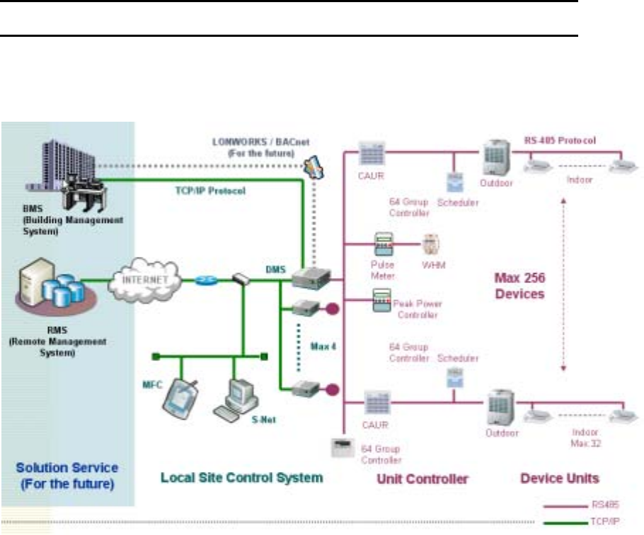
1.1. DMS System Feature
1.1.1. System Establishment Environment
1.2. Introduction of DMS Function
1.2.1. DMS Main Function
1) Wink
2) Tracking
3) DVM Monitoring/Controll
4) Fault/Error History Monitoring
5) DVM item inquiry / setting
6) Environment setting
7) DI / DO
8) Schedule setting / inquiry / execution
9) Power division setting / inquiry / data saving
10) Peak power control / setting / inquiry
11) Joint between the DMS’ Peak power control information
DMS User Manual Version 1.0
Software Center, Samsung Electronics Co., Ltd. 4
12) Information inquiry / settion of the demand controller
1.2.2. Console Function
13) Network information inquiry / setting
14) Information inquiry / setting of the service server
15) Inquiry / setting of the data
16) Inquiry of tracking information / Execution of tracking
17) Setting of DMS cryptograph
18) Master DMS inquiry / setting
19) Inquiry / initialize of the setting information priority order
20) DMS rebooting
1.2.3. Web Function
1) Login
2) Monitoring / contorling
3) Inquiry of the defect history
4) Set / inquiry of the schedule setting
5) Set / inquiry of the peak power
6) Set / inquiry of the power division
7) Set / inquiry of the system circumstance
8) Tracking
9) User management

Software Center, Samsung Electronics Co., Ltd. 5
2. DMS Installation
2.1. Prapration of the installation
2.1.1. Confirmation of the package
DMS Case(UM 32009L) 1SET / pannel 2EA
DMS Main Board, Sub Board, Cable
Serial Cable 1EA
Power Cable 1EA
Ethernet Cable 1EA
2.1.2. Check list before the installation
Confirmation of the CAUR’ s operation
DMS control the DVM System Air conditioner through controlling the CAUR. So, DMS
can not control the air conditioner if the communication between the CAUR and
outdoor equipments operates normally.
And if CAUR can not detect the outdoor equipments, DMS can not detect the outdoor
equipments and indoor equipments. So DMS must detect all outdoor and indoor
equipments and confirm of the normal communication.
Confirmation of the PC serial port’ s normal operation
If you want to use the console function, serial port’ s normal operation is necessary.
So, confirm that serial port is operating normally.
Comfirmation of the operation LAN
Because DMS communicate with upper controller through TCP/IP, normal operation of
the LAN is necessary. If network is not working, you only can use console function.
2.1.3. Software Requirements
DMS can be set by console and web. It is necessary software requirements of below to do normally.
- Serial program to connect the console(Windows’ hyperterminal)
- Java Runtime Environment 1.3.1
- Internet Explore 6.0
2.2. Installation
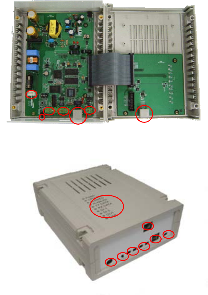
2.2.1. DMS Interface
DI DO
Reset
Power
Ethernet
RS-485 Serial
LED
Power
DO
DI
Reset
Ethernet
RS-485
Serial
DMS User Manual Version 1.0
Software Center, Samsung Electronics Co., Ltd. 7
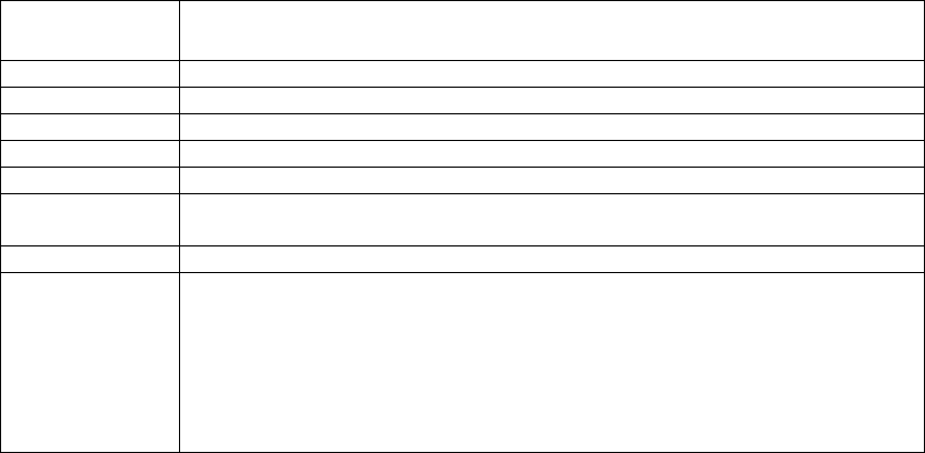
Item Contents
Power Supply the power.
Reset Used in system reset.
DI Connected to switch to create signal.
DO Control the on/off of the relay.
Ethernet Connected to i-MFC, S-Net and Service Server though LAN cable
RS-485 Connected to CAUR, outdoor equipment and indoor equipment through coaxial
cable. And then DMS collect the data and control through this.
Serial Used Version Upgrade and checking the defect.
LED
Display the system status.
Power – Checking the system on / off
CPU Alive – Checking the system’s normal operation
nLinked / nLanLED – Checking the Ethernet’s connections and operation
Tx Data / Rx Data – Checking the RS-485’s status
DI 1/2 – Checking the DI’s operation
DO 1/2 – Checking the DO’s operation
DMS User Manual Version 1.0
Software Center, Samsung Electronics Co., Ltd. 8
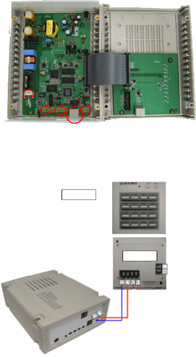
2.2.2. DMS Connection
1) Power : Connect to AC Power through power cable.
2) DI : Connect to external switch. Be careful of +, - sign.
3) DO : Connect to external relay. Becareful of +, - sign.
4) Ethernet : Connect to LAN Cable.
5) RS-485 : Connect to CAUR. Be careful of C1, C2 sign.
DI DO
Power
Ethernet
RS-485
Ba
c
k
s
i
de
C
a
u
r

DMS User Manual Version 1.0
Software Center, Samsung Electronics Co., Ltd. 9
2.3. Check list after installation
Check the LED status displayed on the case after all connection is cleared.
LED name Contents
Power If the power is supplied, this LED is turn on.
Initial state is off.
CPU Alive If the CPU is alive, this LED is twinkling
Initial state is off.
nLinked If LAN cable is connected, this LED is turn on.
Initial state is off.
nLanLED If data reception/transmition is occurred through LAN cable, this LED is turn
on.
Initial state is off.
Tx Data If data transmition is occurred through coaxial cable, this LED is turn on.
Initial state is off.
Rx Data If data reception is occurred through coaxial cable, this LED is turn on.
Initial state is off.
DI 1 / 2 If external switch is pressed, this LED is turn on.
Initial state is off.
DO 1 Checking the status of indoor equipment. If one of the indoor equipments is turn
on, then, this LED is turn on.
Initial state is off.
DO 2 Checking the status of indoor equipment. If one of the indoor equipments have a
defect, LED is turn on.
Initial state is off.
THIS DEVICE COMPLIES WITH PART 15 OF THE FCC RULES. OPERATION
IS SUBJECT TO THE FOLLOWING TWO CONDITIONS: (1) THIS DEVICE MAY
NOT CAUSE HARMFUL INTERFERENCE, AND (2) THIS DEVICE MUST
ACCEPT ANY INTERFERENCE RECEIVED, INCLUDING INTERFERENCE THAT
MAY CAUSE UNDESIRED OPERATION.
NOTE: THE MANUFACTURER IS NOT RESPONSIBLE FOR ANY
RADIO OR TV INTERFERENCE CAUSED BY UNAUTHORIZED
MODIFICATIONS TO THIS EQUIPMENT. SUCH MODIFICATIONS
COULD VOID THE USER'S AUTHORITY TO OPERATE THE EQUIPMENT.
NOTE: This equipment has been tested and found to comply with the
limits for a Class B digital device, pursuant to part 15 of the FCC
Rules. These limits are designed to provide reasonable protection
against harmful interference in a residential installation. This
equipment generates, uses and can radiate radio frequency energy
and, if not installed and used in accordance with the instructions, may
cause harmful interference to radio communications. However, there
is no guarantee that interference will not occur in a particular
installation. If this equipment does cause harmful interference to
radio or television reception, which can be determined by turning the
equipment off and on, the user is encouraged to try to correct the
interference by one or more of the following measures:
- Reorient or relocate the receiving antenna.
- Increase the separation between the equipment and receiver.
-Connect the equipment into an outlet on a circuit different from that
to which the receiver is connected.
-Consult the dealer or an experienced radio/TV technician for help