Samsung Electronics Co BTW200 2 Channel Audio Transmitter User Manual
Samsung Electronics Co Ltd 2 Channel Audio Transmitter Users Manual
UserManual.wiki
>
Samsung Electronics Co
>
BTW200 User Manual
Users Manual
Navigation menu
Upload a User Manual
Namespaces
Wiki Guide
HTML
PDF
Info
Views
User Manual
Discussion / Help
Navigation
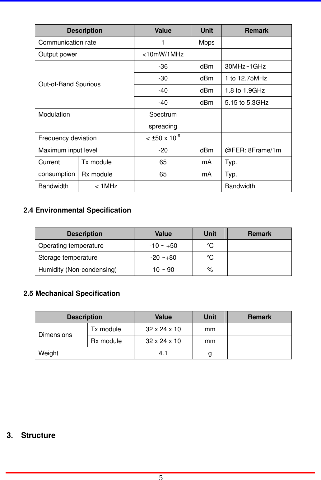
![4Description Value Unit Remark Frequency range 2,402 ~ 2,480 MHz Antenna impedance 50 ohm Refer to the specification of antenna. Data communication Half duplex Frequency type F2D [Specification of antenna] - Tx Antenna Specification Electrical Specification Frequency Range 2402 ~ 2480 MHz V.S.W.R 1.6: 1 (max) Gain(Max) 1.6 dBi Nominal Impedance 50 ohm Polarization Linear Mechanical Specification Dimensions 12.8*3.9*1.1 Weight 0.1g Radiator Copper Operating Temp -40 ~ 85 ℃ Operating Humidity 10 ~ 90 % Option SMD 2.3 Electrical Specification](https://usermanual.wiki/Samsung-Electronics-Co/BTW200/User-Guide-521942-Page-4.png)
![6 3.1 Diagram Transceiver module is consist of digital block and RF block. Digital block is for controlling signal and RF block is for connecting wireless signal. [Top] [Bottom] 3.2 PCB Profile The PCB of transceiver is 4 layers and following is detailed information. z PCB material: RCC and FR-4 z PCB Layer: 4 layer Impedance Board z PCB Size: Tx Module -Æ 32 mm(L) × 24 mm(W) × 10 mm(T) Rx Module -Æ 32mm(L) × 24 mm(W) × 10 mm(T)](https://usermanual.wiki/Samsung-Electronics-Co/BTW200/User-Guide-521942-Page-6.png)