Samsung Electronics Co BTW200 2 Channel Audio Transmitter User Manual
Samsung Electronics Co Ltd 2 Channel Audio Transmitter Users Manual
Users Manual

1
SPECIFICATION FOR APPROVAL
Customer:
Address:
Issue No.
Part No. BTW200
Description:
Manufacturer Samsung Electronics Huizhow CO., LTD.
Vendor:
Approved by: BLUE TEK CO., LTD.
Approved
Date:
MM/DD/YY: 01/ 03 /2005
BLUE TEK CO., LTD.
416, Maetan-3Dong, Paldal-Gu, Suwon City, Kyungki-Do, Korea 442-742
TEL: +82-31-200-8672 FAX:+82-31-200-4390
http://www.bluetek.co.kr

2
Abbreviations
. ADC: Analog to Digital Converter
. AGC: Automatic Gain Control
. ANT: Antenna
. BBP: Base Band Processor
. bps : Bit per second
. BT : Bluetooth
. DAC: Digital to Analog Converter
. FHSS : Frequency Hopping Spread Spectrum
. GFSK : Guassian Frequency Shift Keying
. ID : Identification
. I/O: Input/Output
. ISM: Industrial Scientific Medical Frequency Band
. LDO: Low Drop Out Regulator
. LNA: Low Noise Amplifier
. L/R : Left/Right
. MCU: Micro Process Unit
. PA: Power Amplifier
. PCM : Pulse Code Modulation
. RF: Radio Frequency
. SAW: Surface Acoustic Wave
. SMD: Surface Mounted Device
. Tx : Transmitter
. Rx : Receiver
.

3
1. Introduction
This document is manual for BTW200 module. BTW200 module is for sending & receiving audio data
without wire. Transmission methods are FHSS(Frequency Hopping Spread Spectrum) which is used in
bluetooth technology.
BTW200 is composed of two parts. One is Tx module and the other is Rx module. Tx module is works for
master, which receives and compresses audio signal at baseband chip and sending signal without wire.
Rx module is works for slave, which receives signal without wire. The both modules can send and
receive data each other.
This system is for sending and receiving wireless digital data with CD audio quality. The following
characteristics are for satisfying quality.
- Bluetooth RF chip is used for RF function without wire.
- DWM3100 supports audio interface, works for compressing & decompressing and controls audio codec
& RF modem chip.
- Real-time sending and receiving are available.
- It could works independently without S/W control. To loading parameter for operating DWM3100 when
you turning on the power, Booting EEPROM(128 bytes or 256 bytes) is implemented on set. In addition,
I2C mater function is included for accessing EEPROM.
- There is another interface for testing system, additional data interface and controlling other system.
- CD audio quality is available.
- Data transmission is possible.
- Can avoid interference with other wireless products.
- Operation clock and master clock are used.
32MHz clock for baseband part and RF
2. Standard and general specification
2.1 Standard Specification
- 1Mbps high quality audio data communication
- FHSS
- 2.4GHz ISM band
2.2 General Specification
4
Description Value Unit Remark
Frequency range 2,402 ~ 2,480 MHz
Antenna impedance 50 ohm Refer to the specification of antenna.
Data communication Half duplex
Frequency type F2D
[Specification of antenna]
- Tx Antenna Specification
Electrical Specification
Frequency Range 2402 ~ 2480 MHz
V.S.W.R 1.6: 1 (max)
Gain(Max) 1.6 dBi
Nominal Impedance 50 ohm
Polarization Linear
Mechanical Specification
Dimensions 12.8*3.9*1.1
Weight 0.1g
Radiator Copper
Operating Temp -40 ~ 85 ℃
Operating Humidity 10 ~ 90 %
Option SMD
2.3 Electrical Specification
5
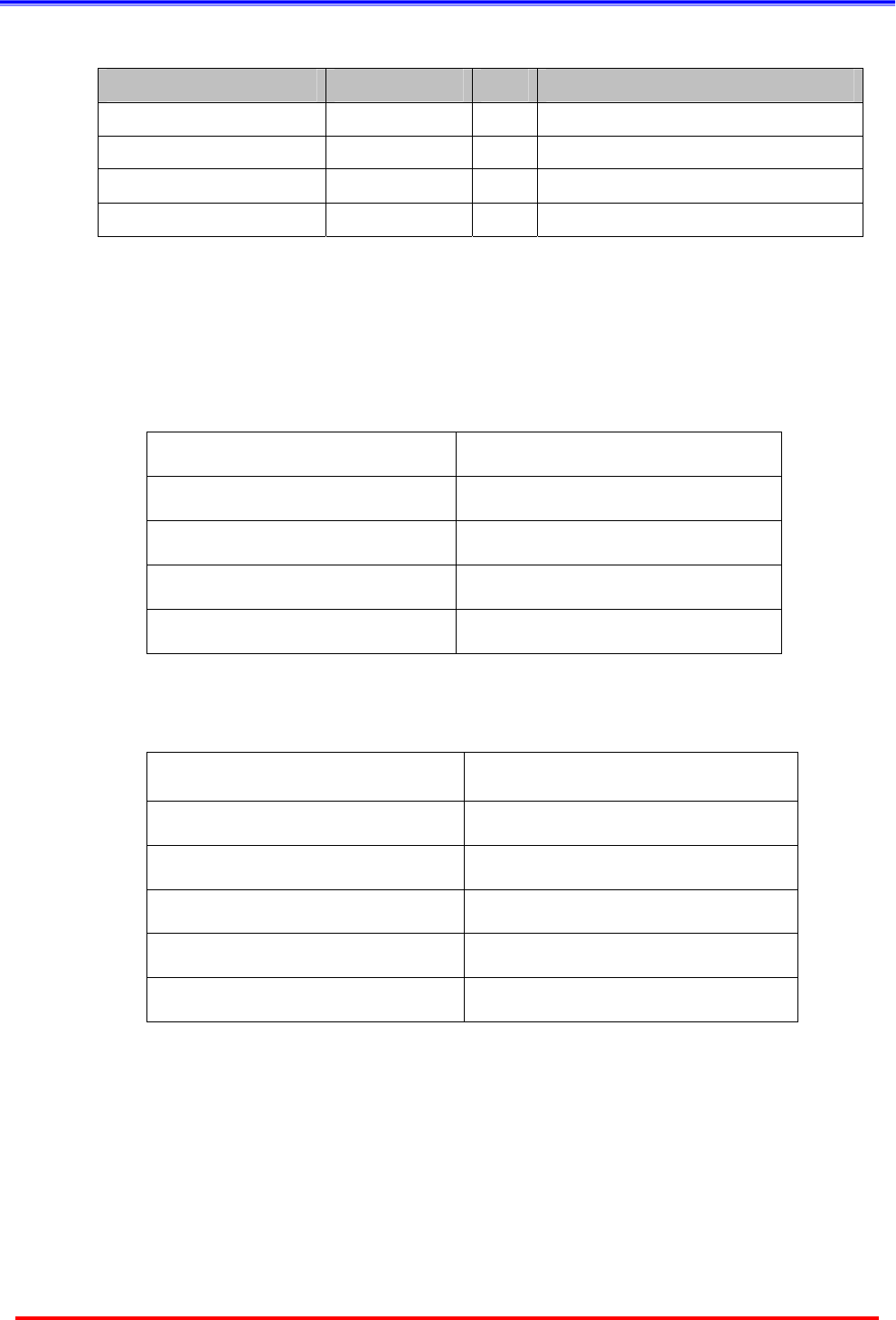
Description Value Unit Remark
Communication rate 1 Mbps
Output power <10mW/1MHz
-36 dBm 30MHz~1GHz
-30 dBm 1 to 12.75MHz
-40 dBm 1.8 to 1.9GHz
Out-of-Band Spurious
-40 dBm 5.15 to 5.3GHz
Modulation Spectrum
spreading
Frequency deviation < ±50 x 10-6
Maximum input level -20 dBm @FER: 8Frame/1m
Tx module 65 mA Typ. Current
consumption Rx module 65 mA Typ.
Bandwidth < 1MHz Bandwidth
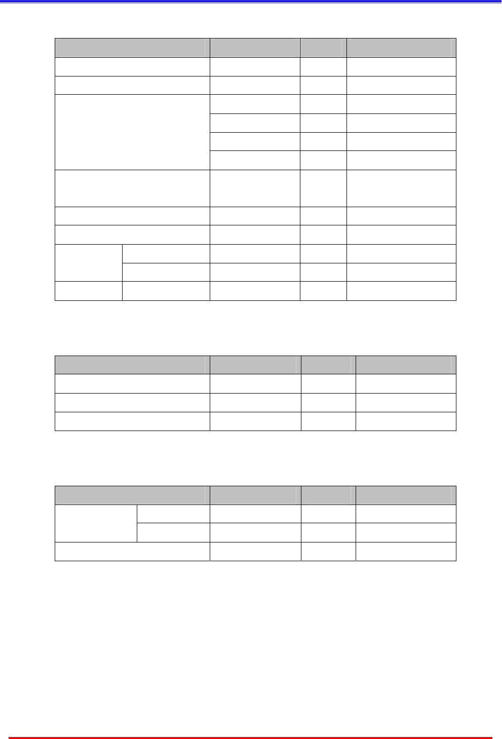
2.4 Environmental Specification
Description Value Unit Remark
Operating temperature -10 ~ +50 °C
Storage temperature -20 ~+80 °C
Humidity (Non-condensing) 10 ~ 90 %
2.5 Mechanical Specification
Description Value Unit Remark
Tx module 32 x 24 x 10 mm
Dimensions Rx module 32 x 24 x 10 mm
Weight 4.1 g
3. Structure
6
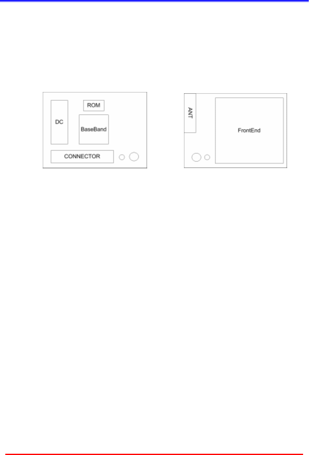
3.1 Diagram
Transceiver module is consist of digital block and RF block. Digital block is for controlling signal and RF
block is for connecting wireless signal.
[Top] [Bottom]
3.2 PCB Profile
The PCB of transceiver is 4 layers and following is detailed information.
z PCB material: RCC and FR-4
z PCB Layer: 4 layer Impedance Board
z PCB Size: Tx Module -Æ 32 mm(L) × 24 mm(W) × 10 mm(T)
Rx Module -Æ 32mm(L) × 24 mm(W) × 10 mm(T)
Regulatory Information
FCC compliance Information
This device complies with part 15 of FCC Rules.
Operation is subject to the following two conditions:
1. This device may not cause harmful interference, and
2. This device must accept any interference received.
Including interference that may cause undesired operation.
Information to User
This equipment has been tested and found to comply with the limits for a Class B digital device,
Pursuant to part 15 of the FCC Rules. These limits are designed to provide reasonable protection
against harmful interference in a residential installation.
This equipment generates, uses and can radiate radio Frequency energy and, if not installed and used
in accordance with the instructions, may cause harmful interference to radio communications.
However, there is no guarantee that interference will not occur in a particular installation. If this
equipment does cause harmful interference to radio or television reception, which can be determined
by turning the equipment off and on, the user is encouraged to try to correct the interference by one or
more of the following measures:
- Reorient or relocate the receiving antenna.
- Increase the separation between the equipment and receiver
- Connect the equipment into an outlet on a circuit different from that to which the receiver is connected.
- Consult the dealer or an experienced radio/TV technician for help.
FCC WARNING: This equipment may generate or use radio frequency energy. Changes or
modifications to this equipment may cause harmful interference unless the modifications are expressly
approved in the instruction manual. The user could lose the authority to operate this equipment if an
unauthorized change or modification is made.
RF Exposure Information: The antenna used for this transmitter must be installed to provide a
separation distance of at least 20 cm from all persons and must not be co-located or operating in
conjunction with any other antenna or transmitter.