Samsung Electronics Co GIS-PAMSC3 SCOPE2.0 Plus User Manual SCOPE2 0 Plus 17 05 24
Samsung Electronics Co Ltd SCOPE2.0 Plus SCOPE2 0 Plus 17 05 24
UserManual.wiki
>
Samsung Electronics Co
>
GIS PAMSC3 User Manual
User Manual
Navigation menu
Upload a User Manual
Namespaces
Wiki Guide
HTML
PDF
Info
Views
User Manual
Discussion / Help
Navigation
![SCOPE2.0 Plus User Manual 1 [ Revision History ] Version Date Change History author Confirmed by V0.1 2016.11.13 Draft Sangho Lee inho.won V0.2 2017.02.02 Add SCOPE2.0Plus Sangho Lee inho.won](https://usermanual.wiki/Samsung-Electronics-Co/GIS-PAMSC3/User-Guide-3412741-Page-2.png)

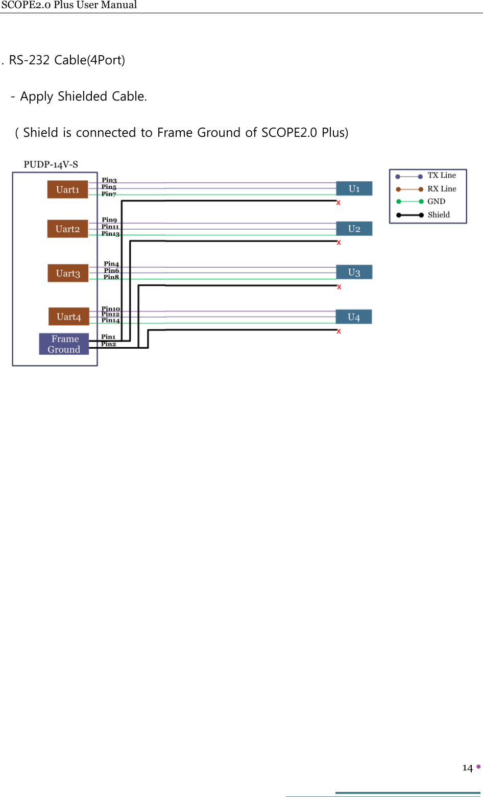
![SCOPE2.0 Plus User Manual 13 [ Cable specification] . Power Cable - A ferrite Core is added to the Power input terminal(Number of turns / 1 turn) ( Using Power Source including a ferrite Core) . LAN Cable(Using Direct Cable) - Apply Shielded LAN Cable - Add Ferrite Core on both end of LAN Cable ( Each Number of turns / 1turn)](https://usermanual.wiki/Samsung-Electronics-Co/GIS-PAMSC3/User-Guide-3412741-Page-14.png)