Samsung Electronics Co GIS-PAMSC3 SCOPE2.0 Plus User Manual SCOPE2 0 Plus 17 05 24
Samsung Electronics Co Ltd SCOPE2.0 Plus SCOPE2 0 Plus 17 05 24
User Manual
SCOPE2.0 Plus
User Manual
(GIS-PAMSC3)
V0.1

SCOPE2.0 Plus User Manual
1
[ Revision History ]
Version
Date Change History author Confirmed
by
V0.1 2016.11.13 Draft Sangho
Lee
inho.won
V0.2 2017.02.02 Add SCOPE2.0Plus Sangho
Lee
inho.won

SCOPE2.0 Plus User Manual
2
1. Introduction
SCOPE2.0 Plus is a device for transferring vibration signal and equipment
information to an agent PC through wired/wireless communication. Users are
advised to read carefully all manuals provided with the package, to ensure safe
and efficient use of SCOPE2.0 Plus unit. This manual explains necessary skills
and information for setting up and using SCOPE2.0 Plus
SCOPE2.0 Plus User Manual
3
2. SCOPE2.0 Plus Specification
SCOPE2.0 Plus Platform comprise two boards(Main Board, Interface Board)
and Sensor Module comprise one board. Each Board Contains following
components
1) Board Components
A. Platform
i. Main Board : CPU / RAM / Flash / Power Module
ii. Interface Board : WIFI / LAN
B. Sensor Module
i. Analog Vibration sensor interface Filter
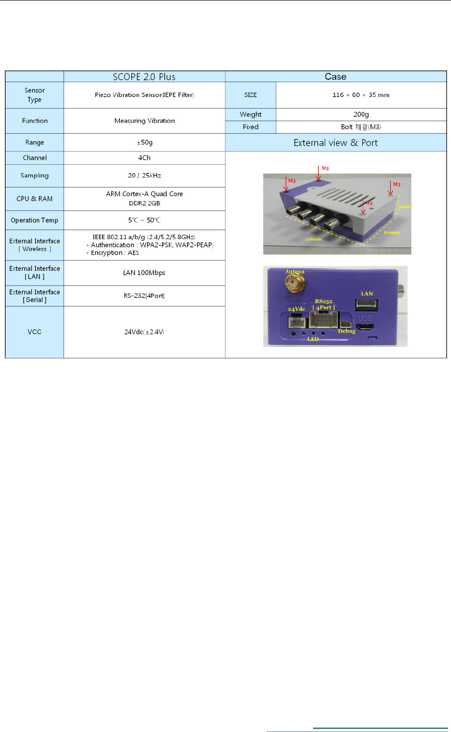
2) Exterior
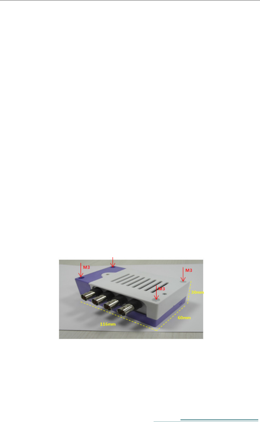
This picture is of SCOPE2.0Plus Board and case. The front panel of
SCOPE2.0 Plus has Power (24Vdc), USB OTG, LAN Port, RS-232 4Port, a
Port of external antenna, LED. The rear panel of SCOPE2.0 Plus has FG.
The Sid panel of SCOPE2.0 Plus has Sensor Connector (BNC)
Figure 1 SCOPE2.0 Plus Exterior
SCOPE2.0 Plus User Manual
4
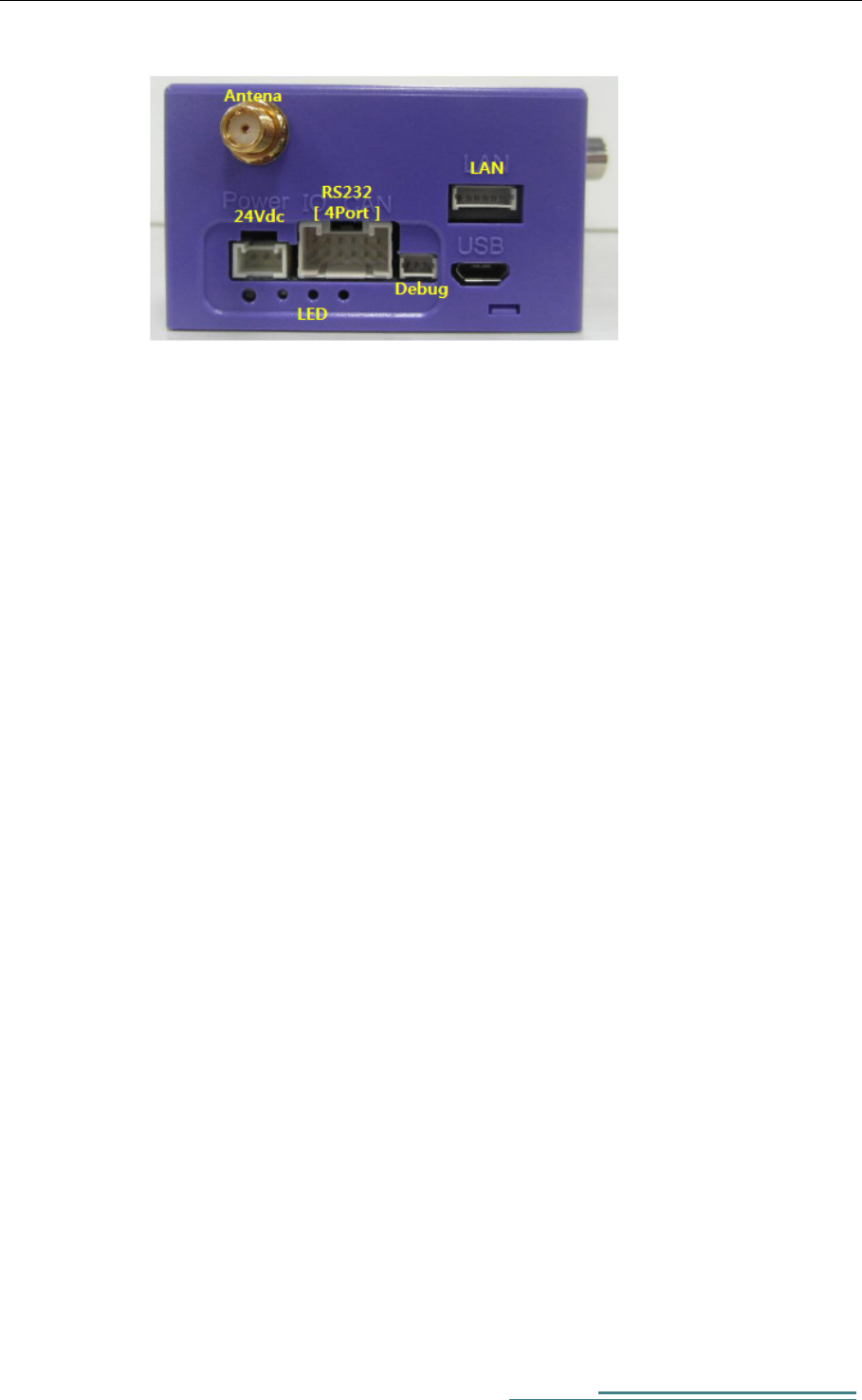
A. Power : 24Vdc supply ( VCC / GND / FG)
B. Antenna : Port for connecting WI-FI module
C. LAN : LAN Port for Ethernet communication with other devices using
TCP/IP
D. USB : USB-OTG Port ( used for FW update)
E. LED(1,2,3) : Status LED
F. FG : Frame Ground for noise reduction. Connects to host equipment
ground
G. RS232 : standard for serial communication transmission of data ( used
for communication between SCOPE2.0 Plus and equipment)
H. Debug : RS232 Debugging Port
Figure 2 SCOPE2.0 Plus Front Exterior
SCOPE2.0 Plus User Manual
5
3) H/W Specification
A. SCOPE2.0 Plus internal H/W has following characteristics
i. Freescale i.MX6 Qual Core(1 ㎓ × 4)
ii. Dual Band WIFI, 802.11 a/b/g, LAN communication support
iii. FPGA(SPARTAN LX4 )support
B. Platform HW Details
ITEM SPECIFICATION
CPU Freescale-i.MX6Q CPU(Quad)
ETHERNET 100M LAN
SERIAL USB to SERIAL Debug port
USB USB2.0 Client Debug port
WIFI 802.11a/b/g
ADC BOARD I/F 8bit Bus, 5V, 3.3V, 24V supply
INDICATOR 3COLOR x2
Digital I/F RS-232 x 4
CONFIG SWITCH TACT SWITCH x 1
FPGA I/F 8bit Bus
FPGA PROGRAMMING SPI 20MHz 1CH
SUPPLY POWER 24V (21.6V~26.4V)
Size 100 x 60 x 40 (mm)

SCOPE2.0 Plus User Manual
6
C. Analog Vibration sensor module Details
ITEM SPECIFICATION
FPGA SPARTAN-6
ADC AD7684 x 4
FILTER IEPE(3MHz)
INPUT ±5V
SUPPLY POWER (1) 3.3V
SUPPLY POWER (2) 5V
SUPPLY POWER (3) 24V
Connector BNC x 4
SCOPE2.0 Plus User Manual
7
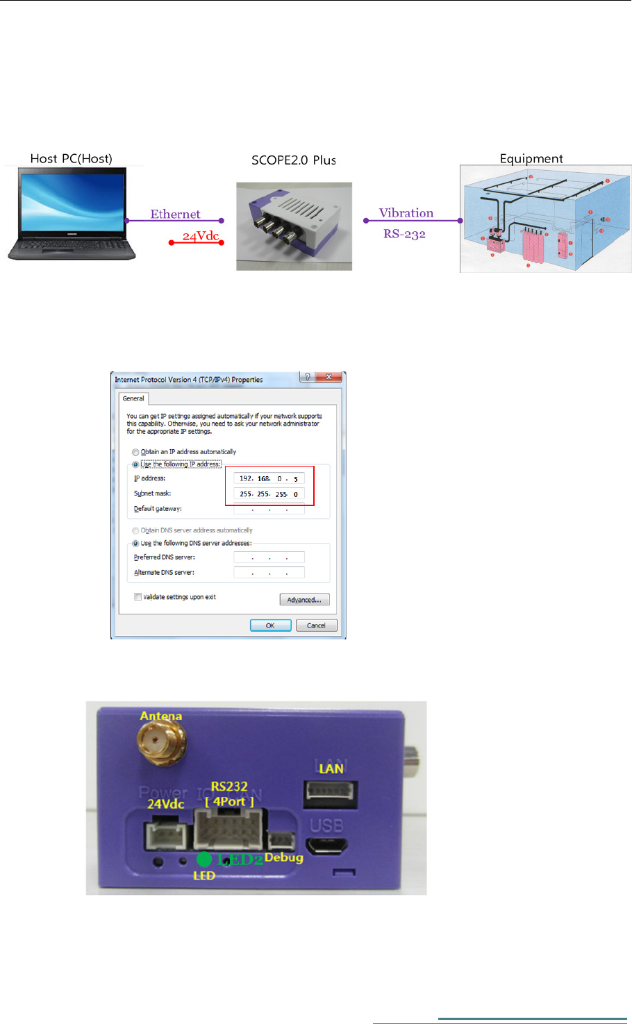
3. How to install and Use
1) SCOPE2.0 Plus installations
2) SCOPE2.0 Plus Connection Check
A. Change IP Address for Data PC to 192.168.0.5
B. Power On and confirm LED2 blinking green.
SCOPE2.0 Plus User Manual
8
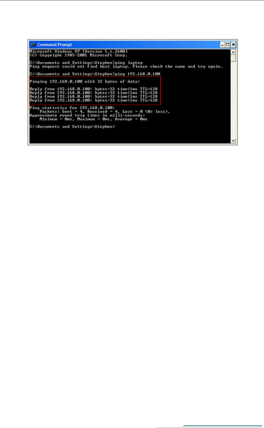
C. Do a ping test to SCOPE2.0 Plus from Data PC to confirm connection
SCOPE2.0 Plus User Manual
9
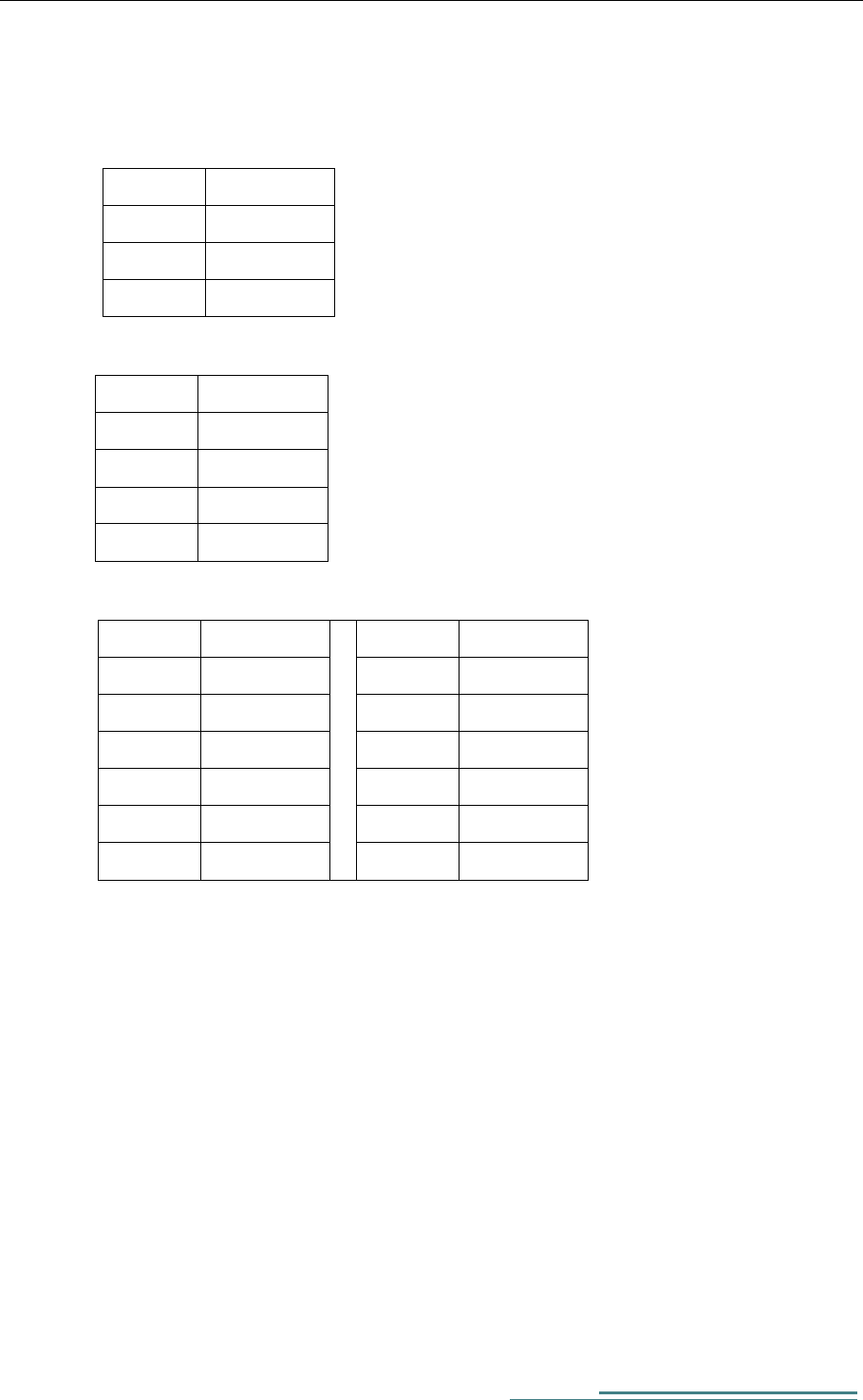
3) SCOPE2.0 Plus Pin Map
A. Power
Pin Num
Description
1 VCC
2 GND
3 FG
B. LAN Port
Pin Num
Description
1 Tx+
2 Tx-
3 Rx+
4 Rx-
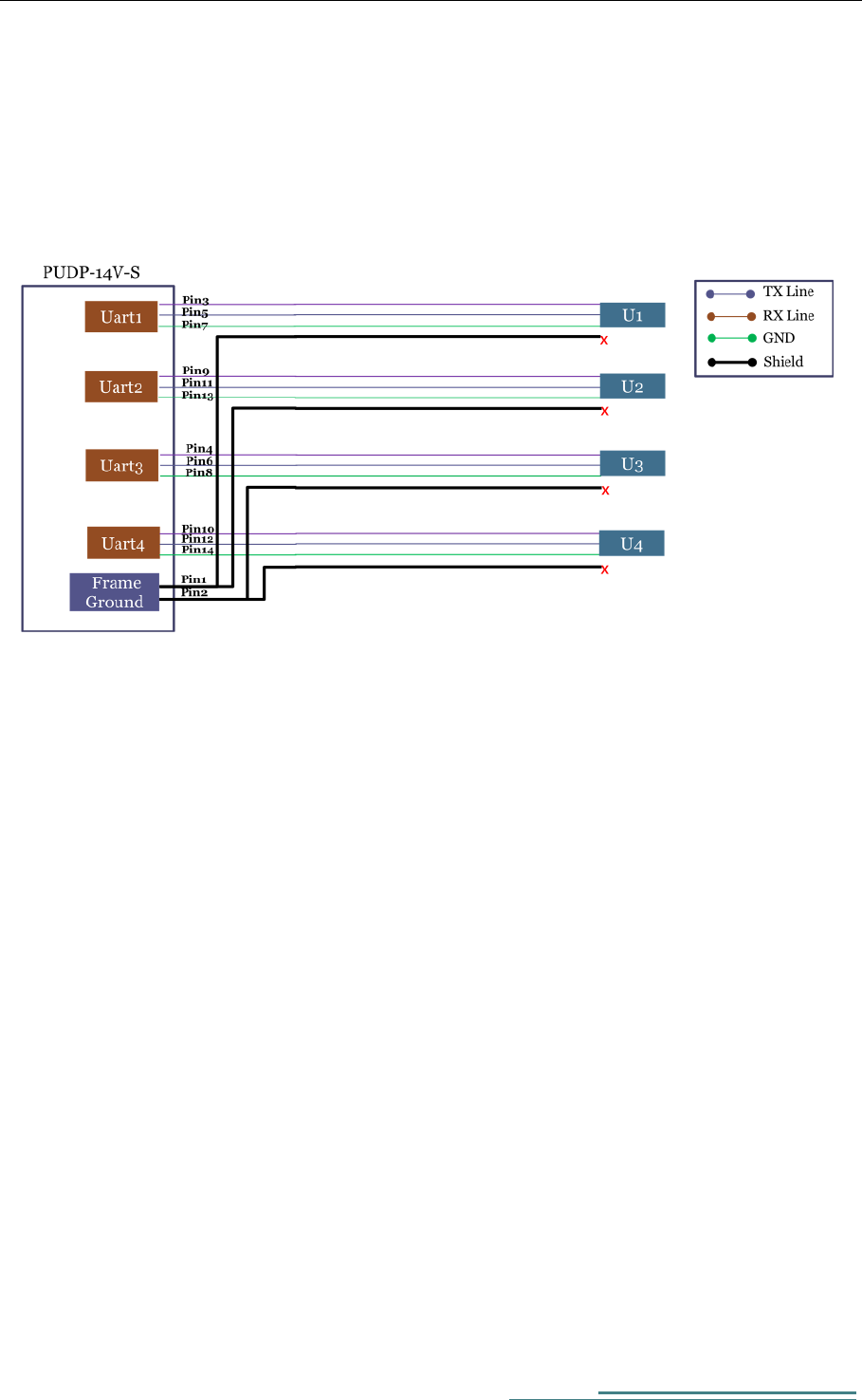
C. RS-232 4Port
Pin Num
Description
Pin Num
Description
1 Ch1 Tx 2 Ch3 Tx
3 Ch1 Rx 4 Ch3 Rx
5 Ch1 GND 6 Ch3 GND
7 Ch2 Tx 8 Ch4 Tx
9 Ch2 Rx 10 Ch4 Rx
11 Ch2 GND 12 Ch4 GND
SCOPE2.0 Plus User Manual
10
4. HW Specifications

SCOPE2.0 Plus User Manual
11
Federal Communication Commission Interference
Statement
This equipment has been tested and found to comply with the limits for a Class B
digital device, pursuant to Part 15 of the FCC Rules. These limits are designed to
provide reasonable protection against harmful interference in a residential
installation.
This equipment generate, uses and can radiate radio frequency energy and, if not
installed and used in accordance with the instructions, may cause harmful
interference to radio communications. However, there is no guarantee that
interference will not occur in a particular installation.
If this equipment does cause harmful interference to radio or television reception
which can be determined by turning the equipment off and on, the user is
encouraged to try to correct the interference by one or more of the following
measures.
- Reorient or relocate the receiving antenna.
- Increase the separation between the equipment and receiver.
- Connect the equipment into an outlet on a circuit different from that to
which the receiver is connected.
- Consult the dealer or an experienced radio, TV technical for help.
- Only shielded interface cable should be used.
Finally, any changes or modifications to the equipment by the user not expressly
approved by the grantee or manufacturer could void the users authority to operate
such equipment.

SCOPE2.0 Plus User Manual
12
This device complies with Part 15 of the FCC Rules. Operation is subject to the
following two conditions: (1) this device may not cause harmful interference, and
(2) this device must accept any interference received, including interference that may
cause undesired operation
Caution : Any changes or modifications in construction of this device which are not
expressly approved by the party responsible for compliance could void the user's
authority to operate the equipment.
This device is operation in 5.15 – 5.25 GHz frequency range, then restricted in indoor
use only.
RF exposure warning
This equipment must be installed and operated in accordance with provided
instructions and the antenna(s) used for this transmitter must be installed to provide a
separation distance of at least 20 cm from all persons and must not be co-located or
operating in conjunction with any other antenna or transmitter.
End-users and installers must be provide with antenna installation instructions and
transmitter operating conditions for satisfying RF exposure compliance.
SCOPE2.0 Plus User Manual
13
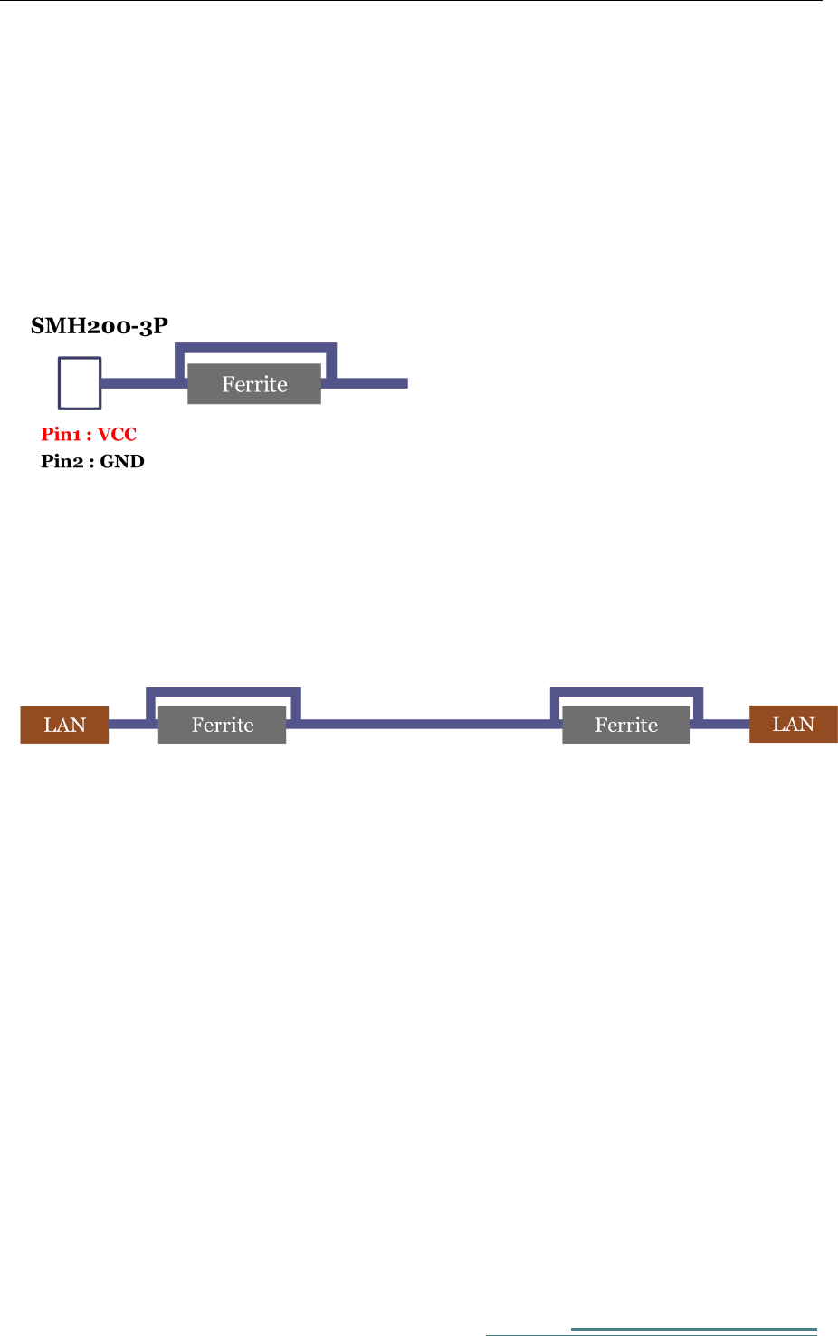
[ Cable specification]
. Power Cable
- A ferrite Core is added to the Power input terminal(Number of turns / 1 turn)
( Using Power Source including a ferrite Core)
. LAN Cable(Using Direct Cable)
- Apply Shielded LAN Cable
- Add Ferrite Core on both end of LAN Cable ( Each Number of turns / 1turn)
SCOPE2.0 Plus User Manual
14
. RS-232 Cable(4Port)
- Apply Shielded Cable.
( Shield is connected to Frame Ground of SCOPE2.0 Plus)