Samsung Electronics Co GIS-PSMPC2 Optical PARTICLE COUNTER User Manual Revision History
Samsung Electronics Co Ltd Optical PARTICLE COUNTER Revision History
UserManual.wiki
>
Samsung Electronics Co
>
GIS PSMPC2 User Manual
User manual
Navigation menu
Upload a User Manual
Namespaces
Wiki Guide
HTML
PDF
Info
Views
User Manual
Discussion / Help
Navigation
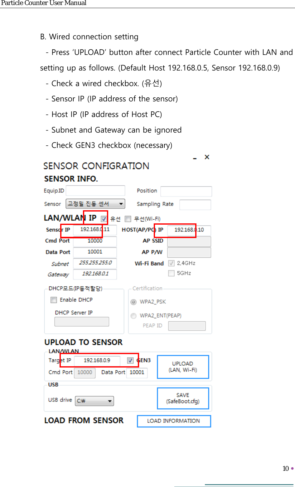
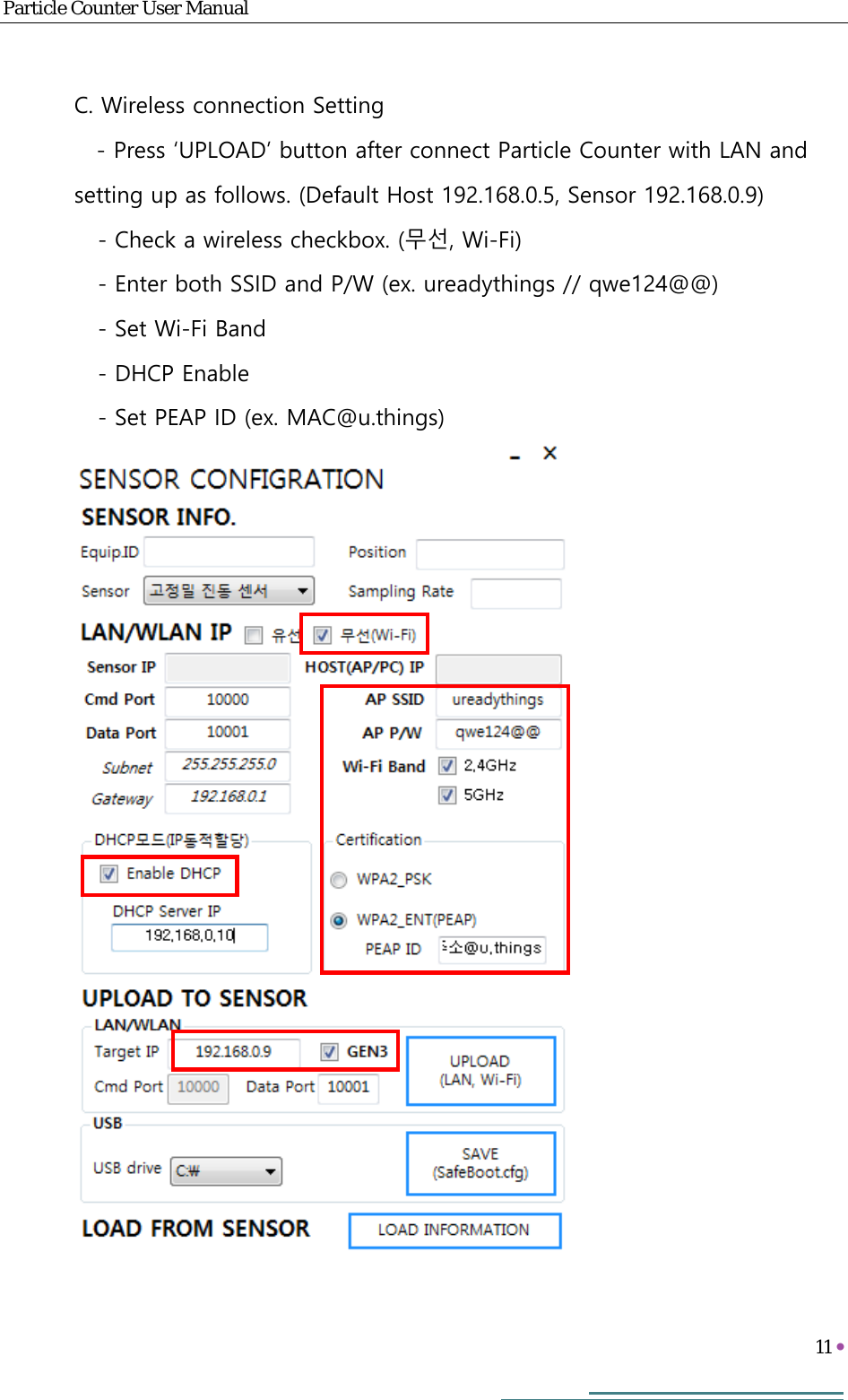
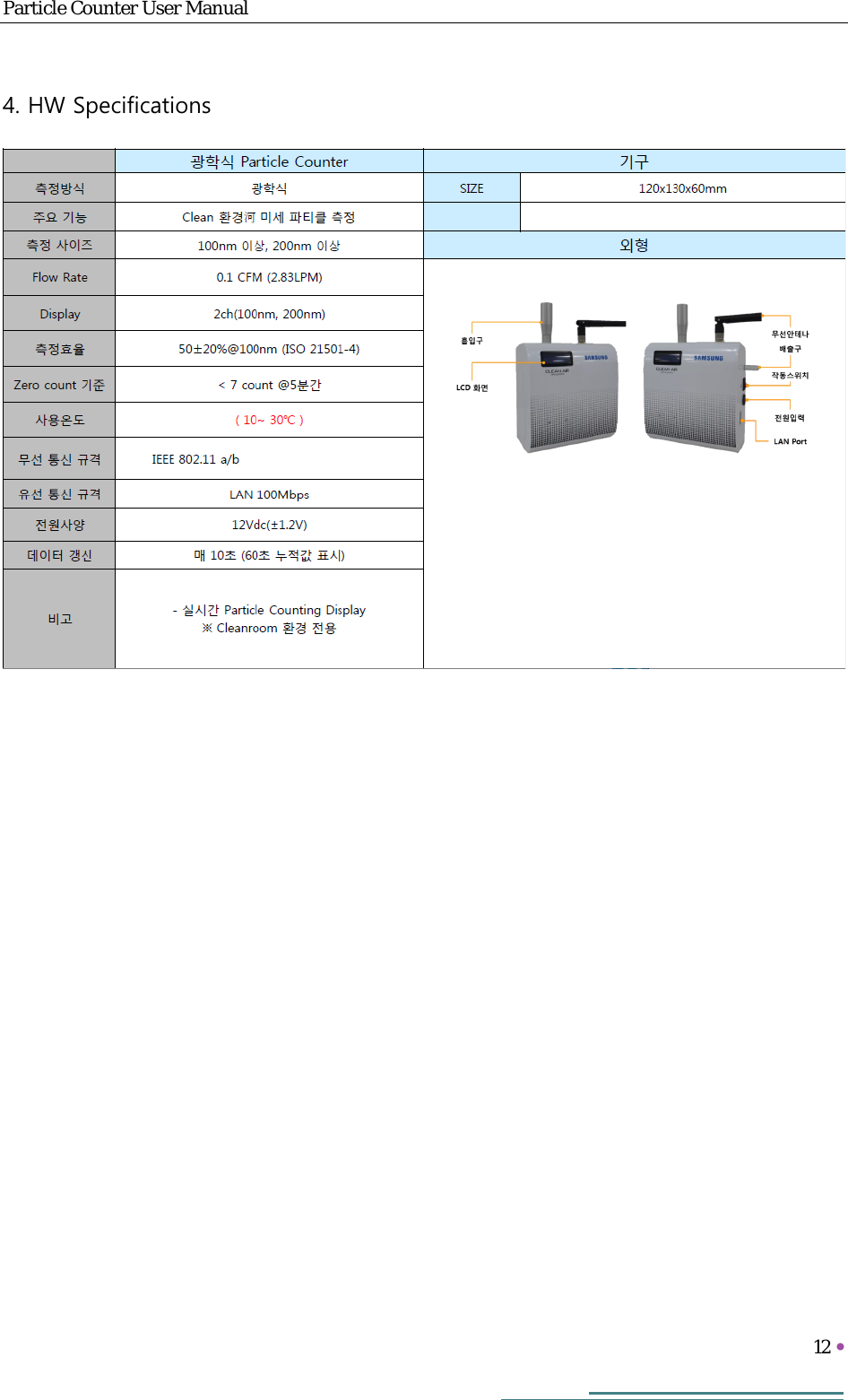
![Particle Counter User Manual 1 [ Revision History ] Version Date Revision history 작성자 책임자 V0.1 2017.07.21 Revised 조성민 하민성 V0.2 2017.11.22 Revised 조성민 박병곤](https://usermanual.wiki/Samsung-Electronics-Co/GIS-PSMPC2/User-Guide-3715037-Page-2.png)