Samsung Electronics Co GIS-PSMPC2 Optical PARTICLE COUNTER User Manual Revision History
Samsung Electronics Co Ltd Optical PARTICLE COUNTER Revision History
User manual
Particle Counter
User Manual
V0.1

Particle Counter User Manual
1
[ Revision History ]
Version Date Revision history 작성자 책임자
V0.1 2017.07.21 Revised 조성민 하민성
V0.2 2017.11.22 Revised 조성민 박병곤

Particle Counter User Manual
2
1. 개요
Particle Counter is a device for acquiring data of particles with the size of
100nm and 200nm, and for transferring the Particle Data to an agent PC
through wired/wireless communication. Users are advised to read carefully all
manuals provided with the package, to ensure safe and efficient use of Particle
Counter. This manual explains necessary skills and information for setting up
and using both Particle Counter and Signal Recorder
Particle Counter User Manual
3
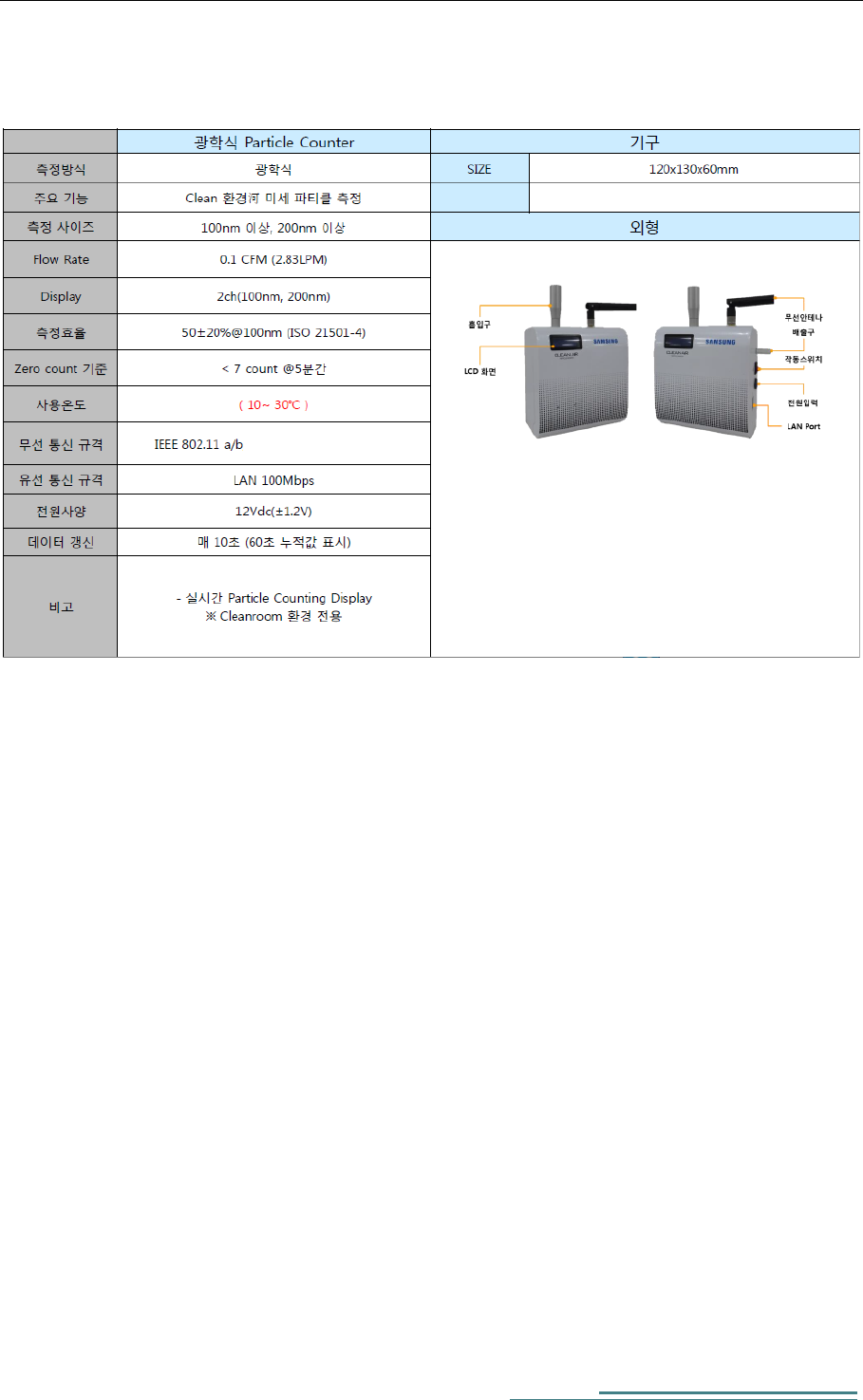
2. Basic specifications of Particle Counter
Particle Counter is comprised of three boards and each board contains
following components
1) Board components
i. Main Board : CPU / Power Module
ii. Interface Board : WIFI / LAN / Flash
iii. Sensor: Laser sensor I/F Module
2) Exterior
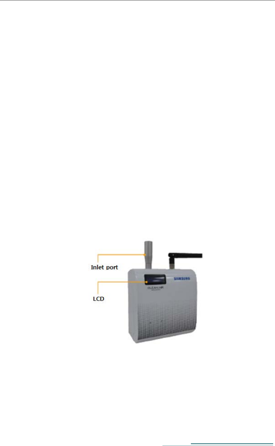
This picture shows an exterior of Particle Counter. The front panel of
Particle Counter has LCD, Port for external antenna, and inlet port for
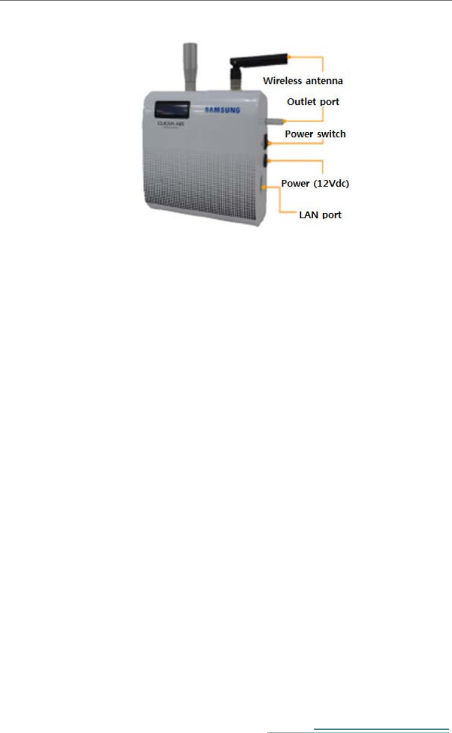
Particle. The side panel of Particle Counter has Power (12Vdc), Power
switch, LAN port, and Serial port (Debug).
Figure 1 Particle Counter Exterior-Front panel
Particle Counter User Manual
4
A. Power : 12Vdc supply (VCC / GND / FG).
B. Antenna: Port for connecting Wi-Fi module (One wireless antenna is
given in the package).
C. LAN : LAN port for Ethernet communication with other devices using
TCP/IP.
D. Debug : RS232 Debugging Port
E. Inlet/Outlet port: Port for inlet/outlet of particle.
3) H/W Specifications
A. Particle Counter internal H/W has following characteristics.
i. Artmega 128 micro controller
ii. Dual Band WIFI, 802.11 a/b , Ethernet communication support
Figure 2 Particle Counter Exterior-Side panel
Particle Counter User Manual
5
B. Particle Counter HW details
3. How to install and use
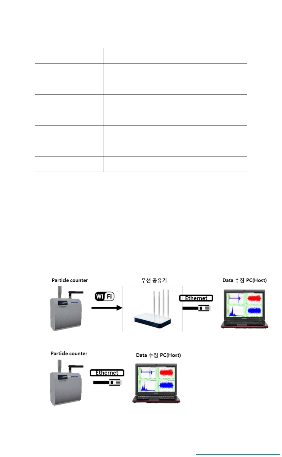
1) Particle Counter installations
A. Wireless connection
B. Wired connection
품목 사양
CPU Atmega 128, CYW43907(Cypress)
ETHERNET GIGABIT-LAN
SERIAL USB to SERIAL Debug port
WIFI 802.11a/b
Power SWITCH ROCKER SWITCH x 1
SUPPLY POWER 12V DC, 1A
Size 120 x 130 x 60 (mm)
Particle Counter User Manual
6
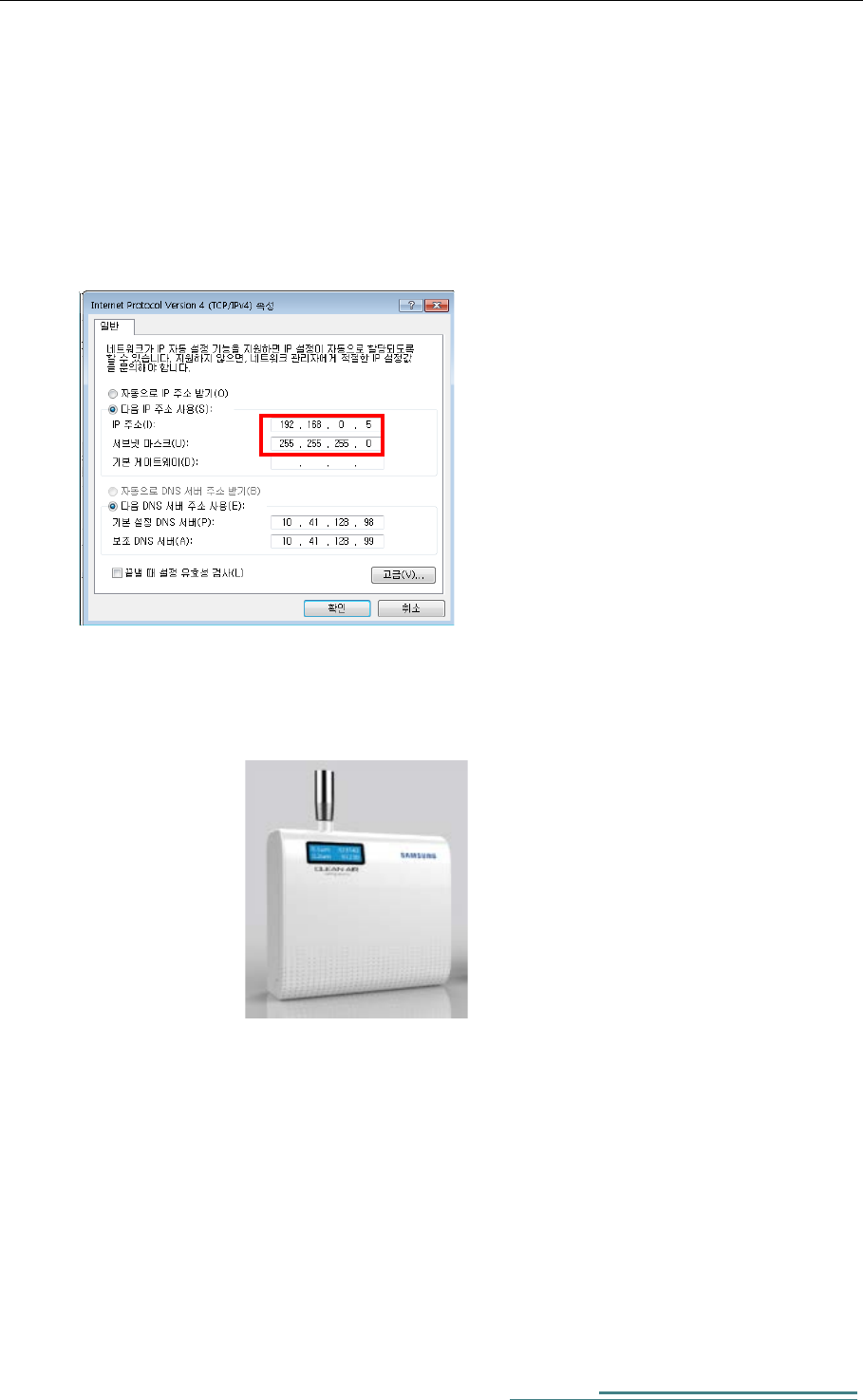
2) Particle Counter connection check
A. Change IP address for Data PC to 192.168.0.5
-Default Host IP : 192.168.0.5
-Default Client IP : 192.168.0.9
(It can be modified through Signal Recorder later)
B. Check a blue light on LCD when the power is on.
Particle Counter User Manual
7
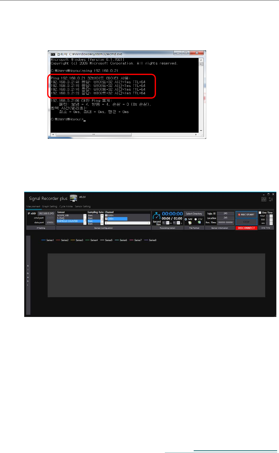
C. Try to ping the Particle Counter from Host PC to confirm connection.
windows > cmd > type “ping 192.168.0.9 –t”
1) How to use SW (Signal Recorder plus)
A. Run Signal Recorder plus.exe
Particle Counter User Manual
8
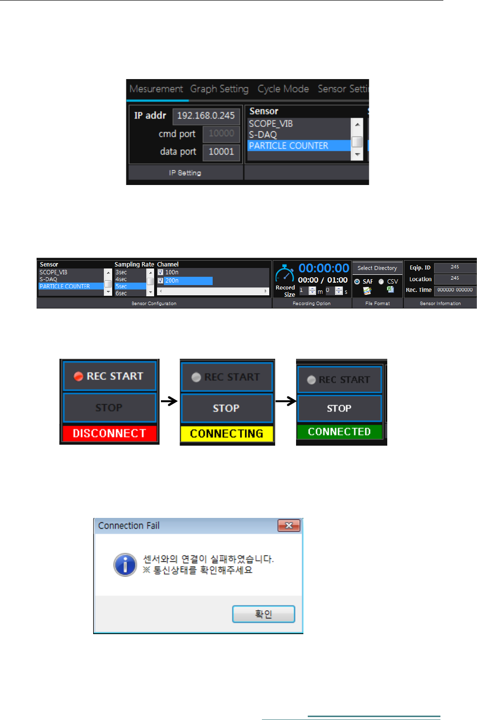
B. Enter IP address of the Particle Counter, and choose Particle Counter
in the list of Sensor.
C. Considering the service environment, choose sampling rate, channel,
recording time, save path, file type (SAF/CSV), and file name.
D. Press start button and confirm that the green ‘CONNECTED’ sign is on.
E. Check LAN cable or wireless AP or IP address of PC and Particle
Counter if you see a popup window as follows.
Particle Counter User Manual
9
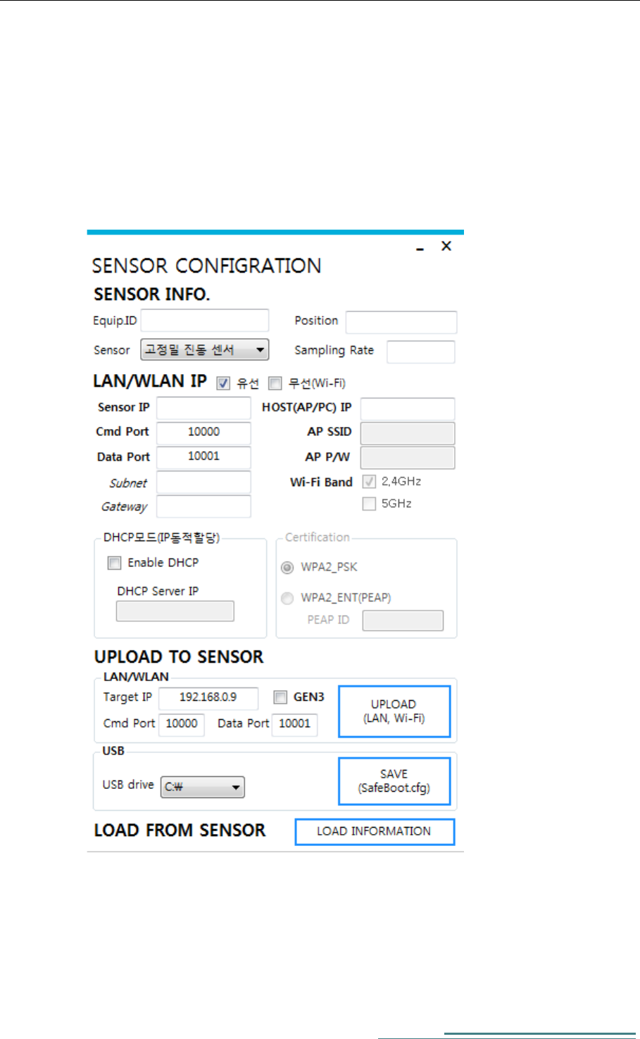
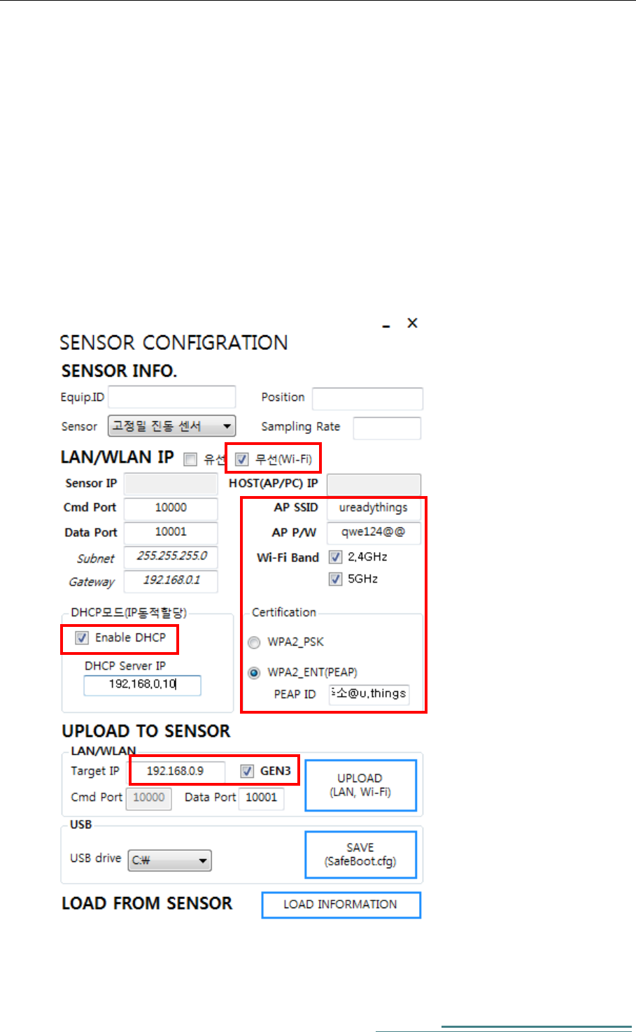
F. Wired/Wireless IP setting
A. IP Setting
- Press ‘Sensor Network Setting’ in ‘Sensor Setting’ of Signal
Recorder Plus, then you can see a popup window as follows.
Particle Counter User Manual
10
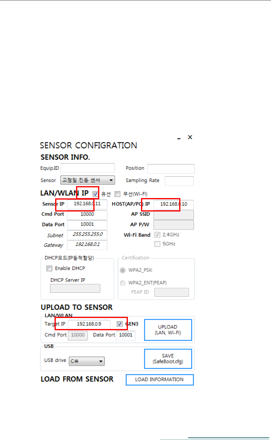
B. Wired connection setting
- Press ‘UPLOAD’ button after connect Particle Counter with LAN and
setting up as follows. (Default Host 192.168.0.5, Sensor 192.168.0.9)
- Check a wired checkbox. (유선)
- Sensor IP (IP address of the sensor)
- Host IP (IP address of Host PC)
- Subnet and Gateway can be ignored
- Check GEN3 checkbox (necessary)
Particle Counter User Manual
11
C. Wireless connection Setting
- Press ‘UPLOAD’ button after connect Particle Counter with LAN and
setting up as follows. (Default Host 192.168.0.5, Sensor 192.168.0.9)
- Check a wireless checkbox. (무선, Wi-Fi)
- Enter both SSID and P/W (ex. ureadythings // qwe124@@)
- Set Wi-Fi Band
- DHCP Enable
- Set PEAP ID (ex. MAC@u.things)
Particle Counter User Manual
12
4. HW Specifications
FCC Compliance Statement
This device complies with part 15 of the FCC rules. Operation is subject to the following two
conditions: (1) This device may not cause harmful interference, and (2) this device must accept any
interference received, including interference that may cause undesired operation.
FCC Interference Statement
This equipment has been tested and found to comply with the limits for a Class B digital device,
pursuant to part 15 of the FCC Rules. These limits are designed to provide reasonable protection
against harmful interference in a residential installation. This equipment generates, uses and can
radiate radio frequency energy and, if not installed and used in accordance with the instructions,
may cause harmful interference to radio communications. However, there is no guarantee that
interference will not occur in a particular installation. If this equipment does cause harmful
interference to radio or television reception, which can be determined by turning the equipment
off and on, the user is encouraged to correct the interference by one of the following measures:
• Reorient or relocate the receiving antenna.
• Increase the separation between the equipment and receiver.
• Connect the equipment into an outlet on a circuit different from which the receiver is connected.
• Consult the dealer or an experienced radio/TV technician for help.
FCC Caution
Any changes or modifications not expressly approved by the party responsible for compliance could
void the user's authority to operate this equipment. This transmitter must not be co-located or
operating in conjunction with any other antenna or transmitter.
FCC Radiation Exposure Statement
This equipment complies with FCC radiation exposure limits set forth for an uncontrolled
environment. This equipment should be installed and operated with minimum distance 20 cm
between the radiator and your body. This transmitter must not be co-located or operating in
conjunction with any other antenna or transmitter.
IEEE 802.11b operation of this product in the USA is firmware-limited to channels 1 through 11.