Samsung Electronics Co GTY3400 Cellular/ PCS GSM/ EDGE/ WCDMA Module User Manual 2
Samsung Electronics Co Ltd Cellular/ PCS GSM/ EDGE/ WCDMA Module Users Manual 2
Contents
- 1. Users Manual 1
- 2. Users Manual 2
Users Manual 2
8 SAMSUNG Proprietary-Contents may change without notice
This Document can not be used without Samsung's authorization | Samsung Electronics
8 GT-Y3400 Installation Guide and User Manual
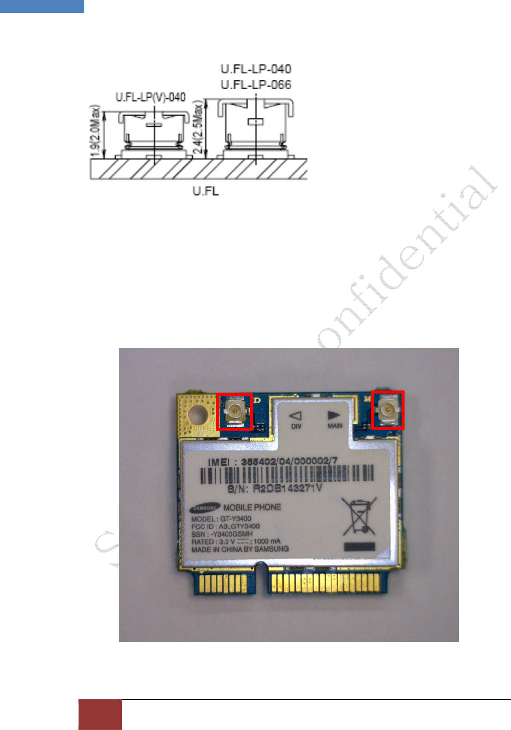
Figure 6. 2D Detail of the antenna connector
Figure 7. Detail of mated height
2.1.4 Connector location
The GT-Y3400 module supports receiver diversity. Both require a secondary antenna
connection. The antenna connectors can be identified by the letters “M” for the main antenna
and “D” for the Diversity, printed on the PCB.
Main Antenna
Diversity Antenna
9 SAMSUNG Proprietary-Contents may change without notice
This Document can not be used without Samsung's authorization | Samsung Electronics
9 GT-Y3400 Installation Guide and User Manual
Figure 8. placement of the antenna connectors for the GT-Y3400
2.1.5 Conducted RF measurement
HSUPA / HSPA+ / UMTS
. Multi-bands variants / 850 / 900 / 1900 / 2100 MHz
. UMTS Power Class 3 (24 dBm)
. HSUPA mode: 5.76 Mbps: category 6
. HSPA+ mode: 21 Mbps: Category 14
EDGE / GPRS
. 850 / 900 / 1800 / 1900 MHz
. GSM Power Class 4 (32dBm) for 850 / 900 bands
. GSM Power Class 1 (28.5dBm) for 1800 / 1900 bands
. EDGE class E2 (26.5 dBm in 850 / 900 bands, 25.8 dBm in 1800 / 1900 bands)
. GPRS / EDGE Multi-slot Class 12 (4 slots Rx, 4 slots Tx)

2.1.6 Installation restrictions and RF Exposure information
The installation of this module is limited to installation by Samsung Electronics IT Company. The
antenna gain used with this module must not exceed 1.4dBi in the 850MHz Cellular band and
1dBi in the 1900MHz PCS Band when it is integrated. This device is approved for use with the
following antenna (or equivalent):
Four S Tech Model: CDMA-DUAL WLL ANTENNA
Type: Dipole Antenna
Bands: CDMA 800MHz, 1900MHz, WCDMA 2.1GHz
RF Exposure – Critical Installation Requirements:
This device is approved for use as a mobile installation meaning that it will only be used in
products that are capable of maintaining a minimum separation distance of 20cm from the
antenna(s) of this device and the end user.
When installed in a final configuration the antenna must be installed such that a minimum
separation of 20 cm (8 inches) between the wireless device and the body of the user (this does
not include extremities) must be maintained during use and while the wireless device is on and
transmitting. This distance must be ensured for all operating modes and conditions.
This transmitter must not be collocated or operate in conjunction with any other antenna or
transmitter.
Installations in which the device is collocated with other transmitters or the minimum separation
distance between the body and antenna(s) can not be maintained require a separate FCC
authorization. Such installations may require additional testing for RF Exposure (i.e. SAR) and a
Class II Permissive Change filing for FCC approval. Please contact Samsung Electronics, Ltd.
regarding such installations.
Labeling:
The host equipment into which the module is installed must be clearly labeled with the FCC
identifier of the module. This label must be permanently installed and can not be placed on a
removable cover or part such as a battery cover. The label must be similar to the following:
Contains FCC ID: A3LGTY3400
Warning:
Any changes or modification to said product not expressly approved by Intel could void the user’s
authority to operate this device.
Confidential Proprietary 4/16
2.2 Antenna_Spec
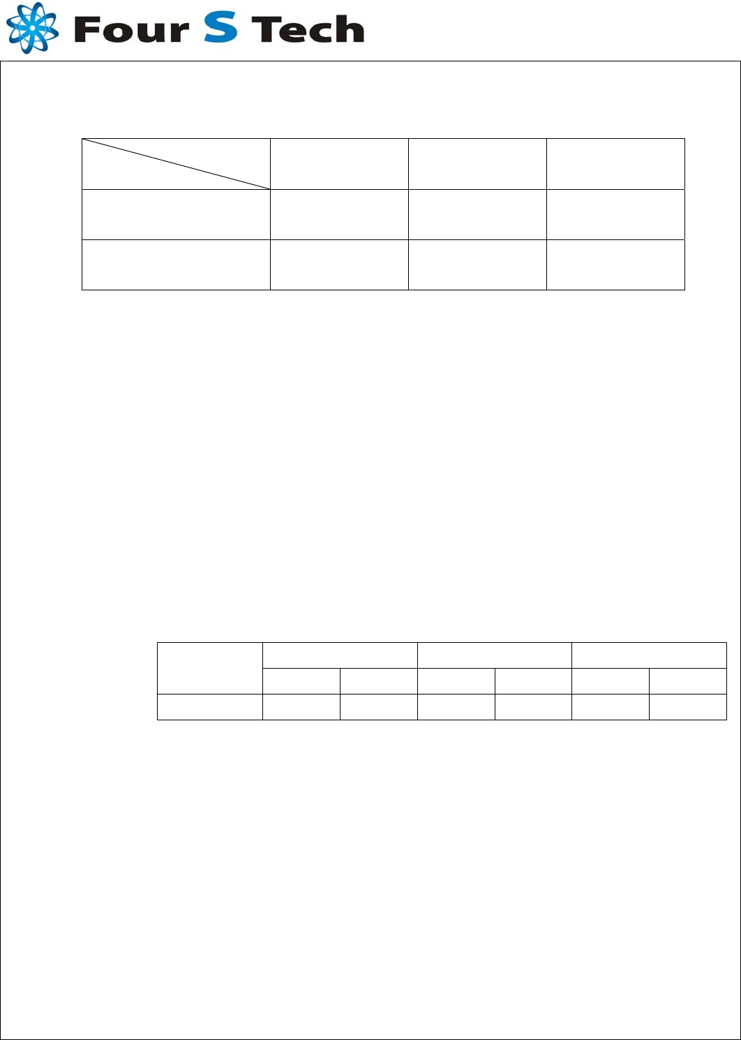
2.2-1 Frequency Band
Service
Band CDMA 800 CDMA 1900 WCDMA 2.1G
Tx ( MH z) 824 ~ 849 1850 ~ 1910 1920 ~ 1980
Rx ( MHz ) 869 ~ 894 1930 ~ 1990 2110 ~ 2170
2.2-2 Impedance
2.2.1 Normal Value
50 ± Normal
2.2.1 Measuring Method
The impedance over the frequency bands shall be as close as possible to
50 after matching. Both free space and talk position are considered.
2.3 VSWR
The impedance matching should be optimized in the more critical talk
position.
2.3.1 Maximum values in free space
CDMA 800 CDMA 1900 WCDMA 2.1G
SERVICE TX Rx TX RX Tx Rx
VSWR 2.7 2.0 2.9 3.4 2.7 1.9
2.3.2 Measuring Method
A 50 coaxial cable is connected(soldered) to the 50 point, at the duplex-
filter on the main PCB. The connection of the coaxial cable shall be done to
introduce a minimum of mismatch. As much as possible the coaxial cable
arrangement shall prevent influences from induced currents on the cable.
In the other end, the coaxial cable is connected to a network analyzer.
The measurement is performed at room temperature. The handset,
including the PCB, must not in any significant way differ from the mass
production, i.e. the antenna feeding network has to be equivalent to the
feeding network in mass production. The specification shall be met in the
entire frequency band.
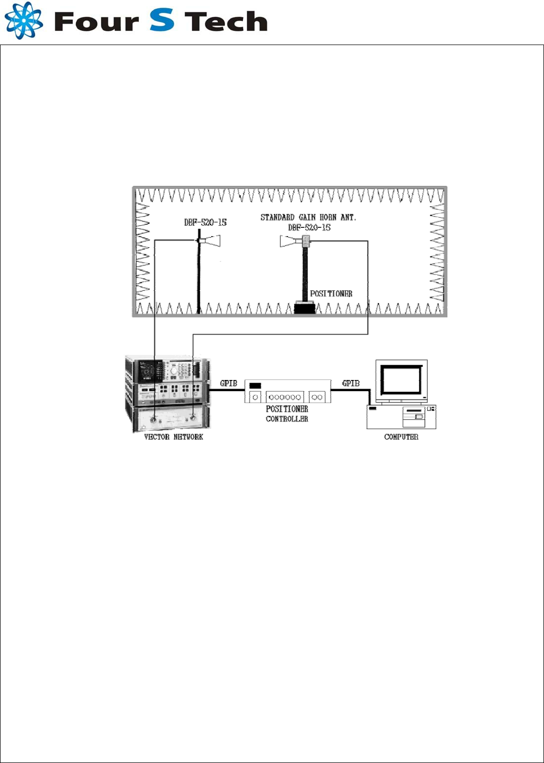
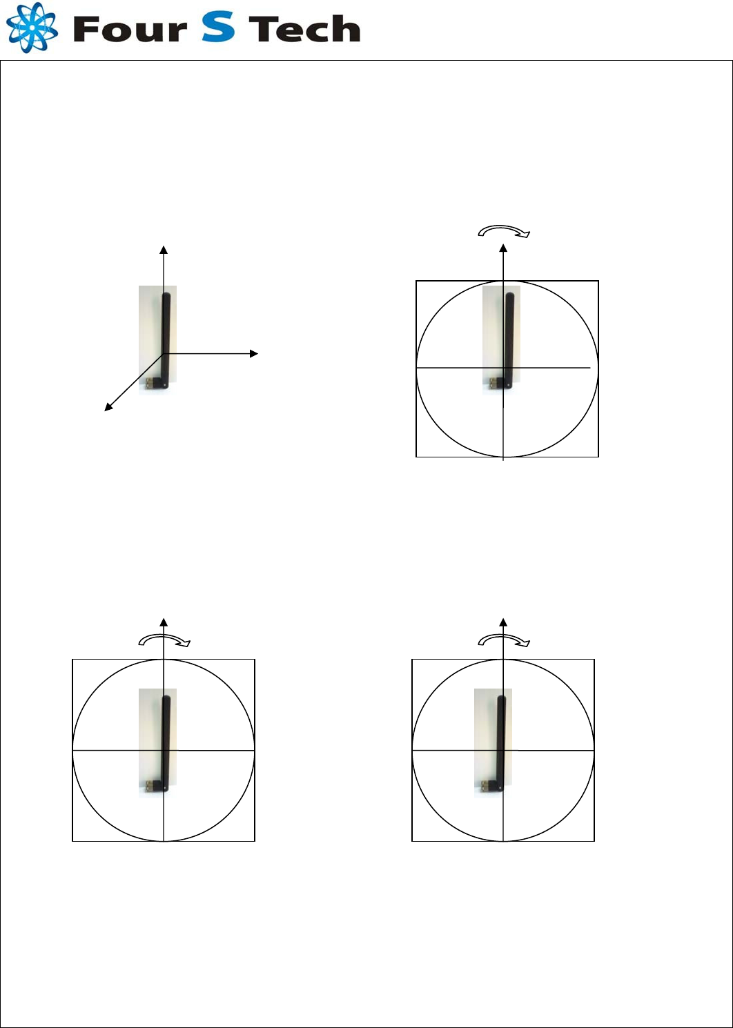
2.4 Gain(dBi)
2.4.1 Measuring Method
The connection is done according to 2.3.2.
Radiation patterns are measured at 3 different Plane
The antenna measured according to the figure 1 below.
figure 1
Confidential Proprietary 5/ 16
2-4-2. Radiation Pattern Measure
Radiation Pattern Measure according to figure2(a), figure2(b),
Scale and Range set up 5dB ,30dB(each).
Figure 2 (a)
Figure 2 (b)
Confidential Proprietary 6/16
X
Y
Z
CW
H
CW
E1
CW
E2
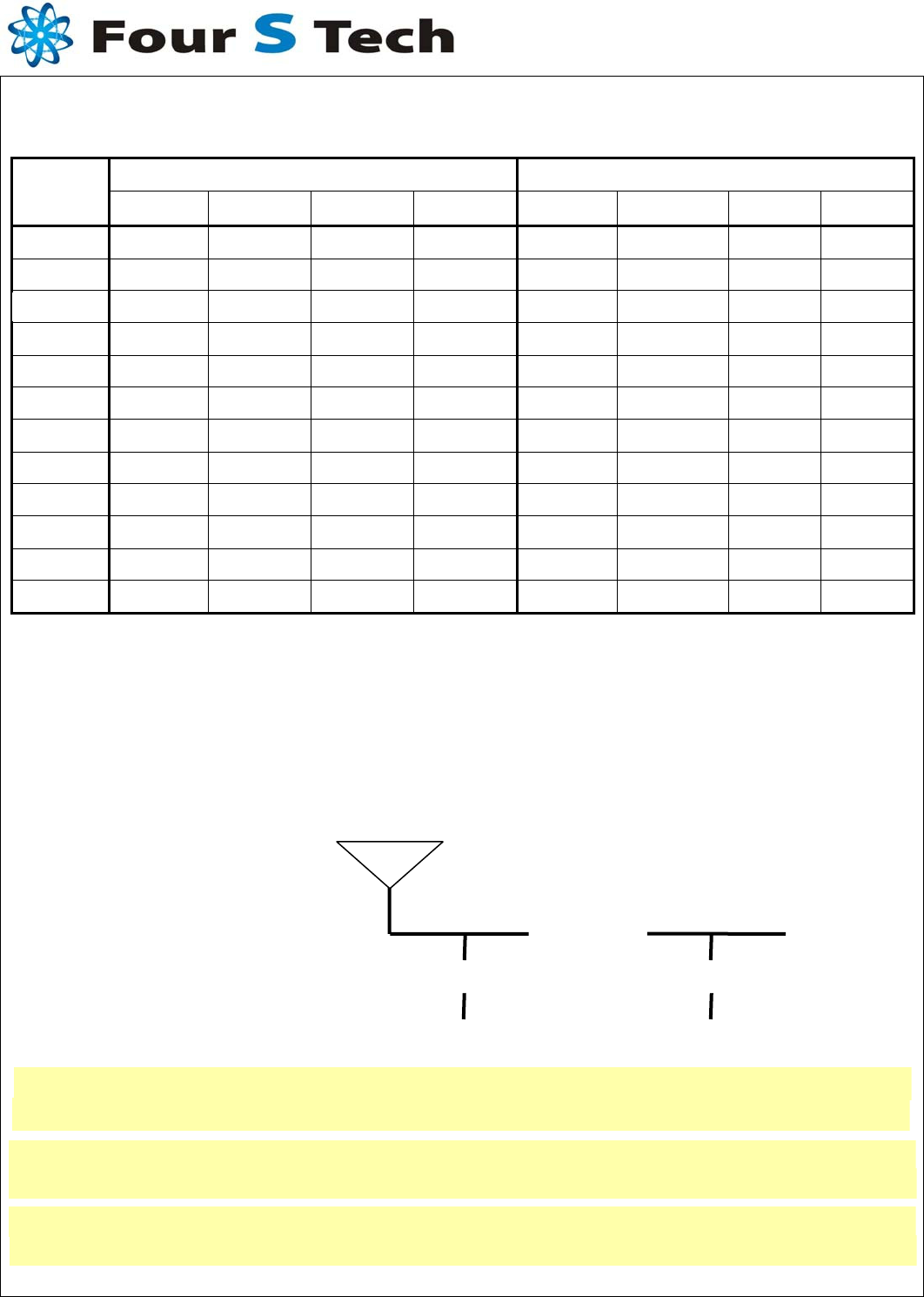
2-4-3 Typical values in maximum direction
Peak Gain [dBi] Avg. Gain [dBi]
Freq.
3DVHsum H E1 E2 3DVHsum H E1 E2
- Antenna Matching Value
Confidential Proprietary 7/16
0 ohm
Open Open