Samsung Electronics Co HG48NC678 LED TV User Manual book of A3LHG48NC678 v1 part1
Samsung Electronics Co Ltd LED TV book of A3LHG48NC678 v1 part1
Contents
- 1. user manual book of A3LHG48NC678_v1 _part1
- 2. user manual book of A3LHG48NC678_v1 _part2
user manual book of A3LHG48NC678_v1 _part1

LED TV
Installation manual
imagine the possibilities
Thank you for purchasing this Samsung product.
To receive more complete service, please
register your product at
www.samsung.com/register
Model Serial No.
[HC670_677_678-ZA]Install Guide-X0ENG.indd 1 2014-01-17 8:47:43

Figures and illustrations in this User Manual are provided for reference only and may differ from actual product appearance.
Product design and specifications may be changed without notice.
Introduction
This TV B2B (Business to Business) model is designed for hotels or the other hospitality businesses, supports a variety of special functions, and lets you
limit some user (guest) controls.
Operational Modes
This TV has two modes : Interactive and Stand-alone mode.
• Interactive mode : In this mode, the TV communicates with and is fully or partially controlled by a connected Set Back Box (SBB) or Set Top Box
(STB) provided by a hospitality SI (System Integration) vendor. When the TV is initially plugged in, it sends a command that attempts to identify the
SSB or STB connected to it. If the TV identifies the SBB or STB and the SBB or STB identifies the TV, the TV gives full control to the SBB or STB.
• Stand-alone mode : In this mode, this TV works alone without an external SBB or the STB.
The TV has a Hotel (Hospitality) Menu that lets you easily set its various hospitality functions. Please see pages 17 to 21.
The Menu also lets you activate or de-activate some TV and hospitality functions so you can create your optimal hospitality configuration.
Still image warning
Avoid displaying still images (such as jpeg picture files) or still image elements (such as TV channel logos, panorama or 4:3 format images, stock or news
bars or crawls) on the screen. Displaying still pictures continually can cause uneven screen wear, which will affect image quality. To reduce the chance that
this effect will occur, please follow the recommendations below:
• Avoid displaying the same TV channel for long periods.
• Always try to display a full screen image.
• Reduce brightness and contrast to help to prevent the occurrence of after-images.
• Frequently use all TV features designed to reduce image retention and screen burn-in. Refer to the proper user manual section for details.
Ensuring Proper Ventilation
When you install the TV, maintain a distances of at least 4 inches between the TV and other object (walls, cabinet sides, etc.) to ensure proper ventilation.
Failing to maintain proper ventilation may result in a fire or problems with the product caused by an increase in its internal temperature.
✎
When using a stand or wall-mount, use parts provided by Samsung Electronics only.
✎
Using parts provided by another manufacturer may cause difficulties with the product or result in injury caused by the product falling.
Installation with a stand. Installation with a wall-mount.
4 inches4 inches
4 inches
4 inches4 inches
4 inches
4 inches
Additional Information
✎
The appearance of the TV and its accessories may differ from the illustrations in this manual, depending on the TV.
✎
Be careful when the you touch the TV. Some parts can be hot.
[HC670_677_678-ZA]Install Guide-X0ENG.indd 2 2014-01-17 8:47:43

3
Contents
ENGLISH
English
yIntroduction .............................................................................................................................................................. 2
yOperational Modes ................................................................................................................................................... 2
yStill image warning .................................................................................................................................................... 2
yEnsuring Proper Ventilation ....................................................................................................................................... 2
yAdditional Information ............................................................................................................................................... 2
yAccessories .............................................................................................................................................................. 4
yInstalling the LED TV Stand ....................................................................................................................................... 5
yAssembling the swivel stand (40 inch TVs or larger) .................................................................................................. 6
yUsing the TV's Controller .......................................................................................................................................... 8
yThe Connection Panel ............................................................................................................................................... 9
yUsing the TV's Controller ........................................................................................................................................ 11
yConnecting the TV to the Lodgenet game controller or a STB of a SI vendor ......................................................... 13
yConnecting the RJP (Remote Jack Pack) ................................................................................................................ 16
ySetting the Hotel Option Data ................................................................................................................................. 18
yInstalling the Wall Mount ......................................................................................................................................... 38
ySecuring the TV to the Wall ..................................................................................................................................... 39
yAnti-theft Kensington Lock ...................................................................................................................................... 40
ySpecifications ......................................................................................................................................................... 41
yDimensions ............................................................................................................................................................. 42
[HC670_677_678-ZA]Install Guide-X0ENG.indd 3 2014-01-17 8:47:43
4
English
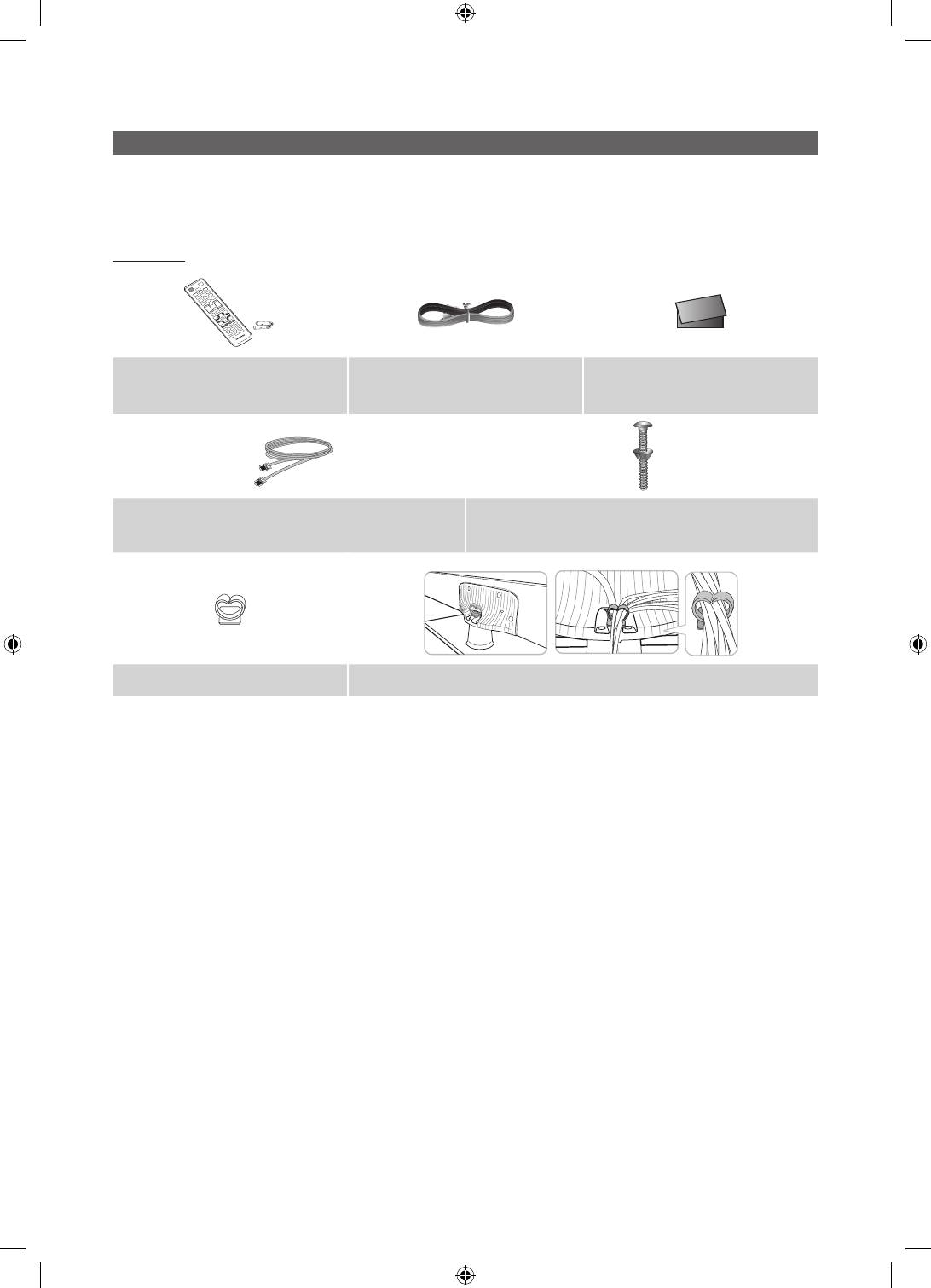
Accessories
✎
Please make sure the following items are included with your LED TV. If any items are missing, contact your dealer.
✎
The items’ color and shape may vary, depending on the model.
✎
The parts for the stand are listed under Stand Components on the following page.
List of Parts
yRemote Control (AA59-00817A) &
Batteries (AAA x 2) yPower Cord ySafety Guide / Quick Setup Guide
(Not available in all locations)
yData Cable (depending on the model) yHotel Mount Kit (BN96-23066A)
yHolder-Wire stand yAssembling the Holder Wire Stand
[HC670_677_678-ZA]Install Guide-X0ENG.indd 4 2014-01-17 8:47:44
5
English
Installing the LED TV Stand
The 32” and larger LED TVs have swivel stands. You can configure these stands so that the TVs swivel 20 degrees left and
right, 60 degrees left and right, or 90 degrees left and right. See page 6.
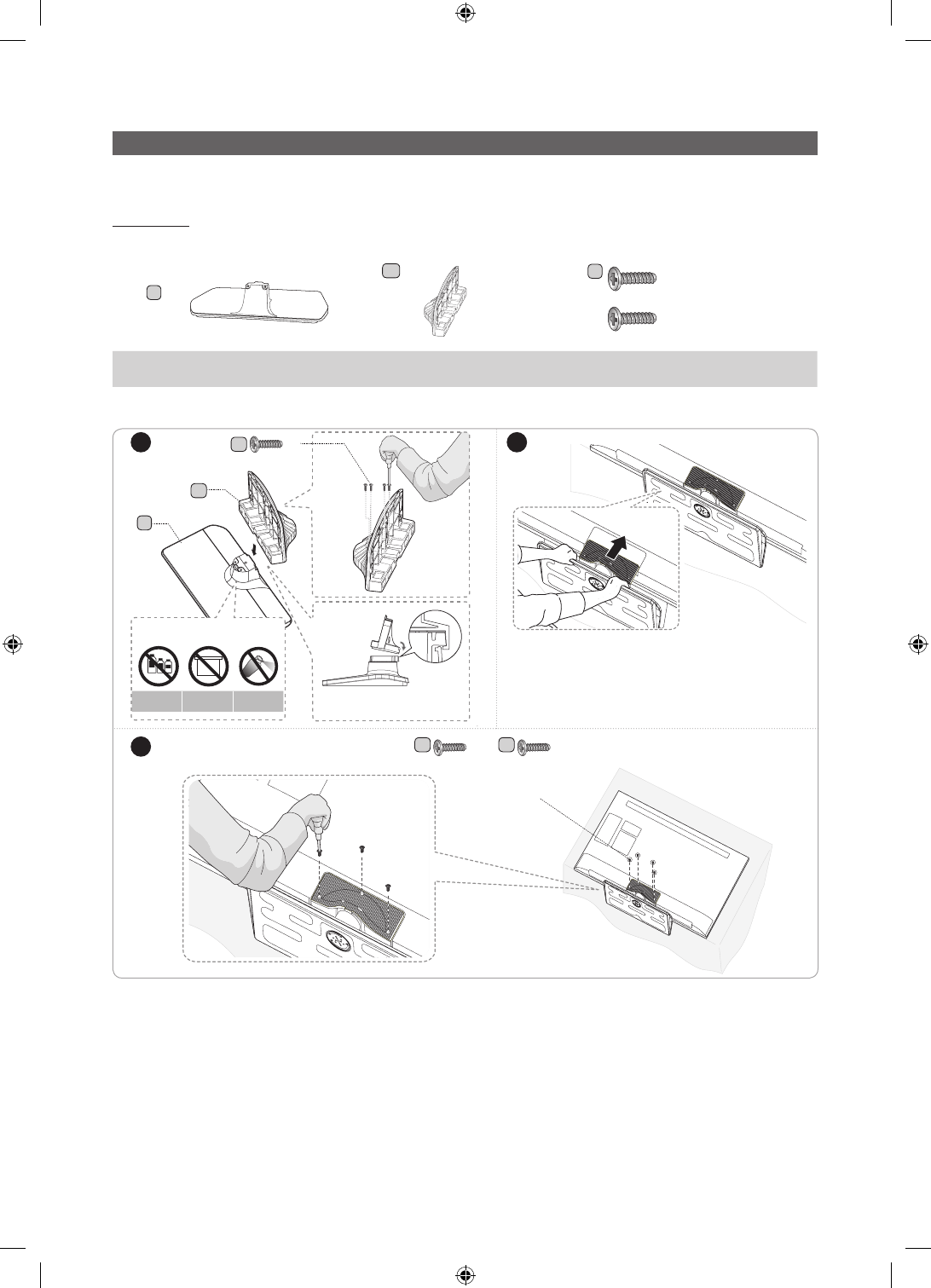
Components
When installing the stand, use the provided components and parts.
A
1 EA
B
1 EA
C
x7 (M4 X L12)
x8 (M4 X L12, for 40"
and above models)
yStand (differs depending on the model)
yGuide Stand yScrews
✎
NOTE
yMake sure to distinguish between the front and back of the Stand and Stand Guide when connecting them.
yMake sure that at least two people lift and move the LED TV.
yThe number of screws may differ depending on the model.
or
1 2
3
A
B
C
x4
(M4 X L12)
Side
Front
DO NOT USE
CHEMICALS
DO NOT USE
GREASE
DO NOT USE
OIL
ATTENTION
✎Place a soft cloth over a table to protect the TV,
and then place the TV on the cloth screen side
down.
✎Insert the Stand Guide into the slot on the bot-
tom of the TV.
Top View
C C
x3 x4
(M4 X L12) (M4 X L12, for 40"
and above models)
or
40"48"model have
[HC670_677_678-ZA]Install Guide-X0ENG.indd 5 2014-01-17 8:47:45
6
English
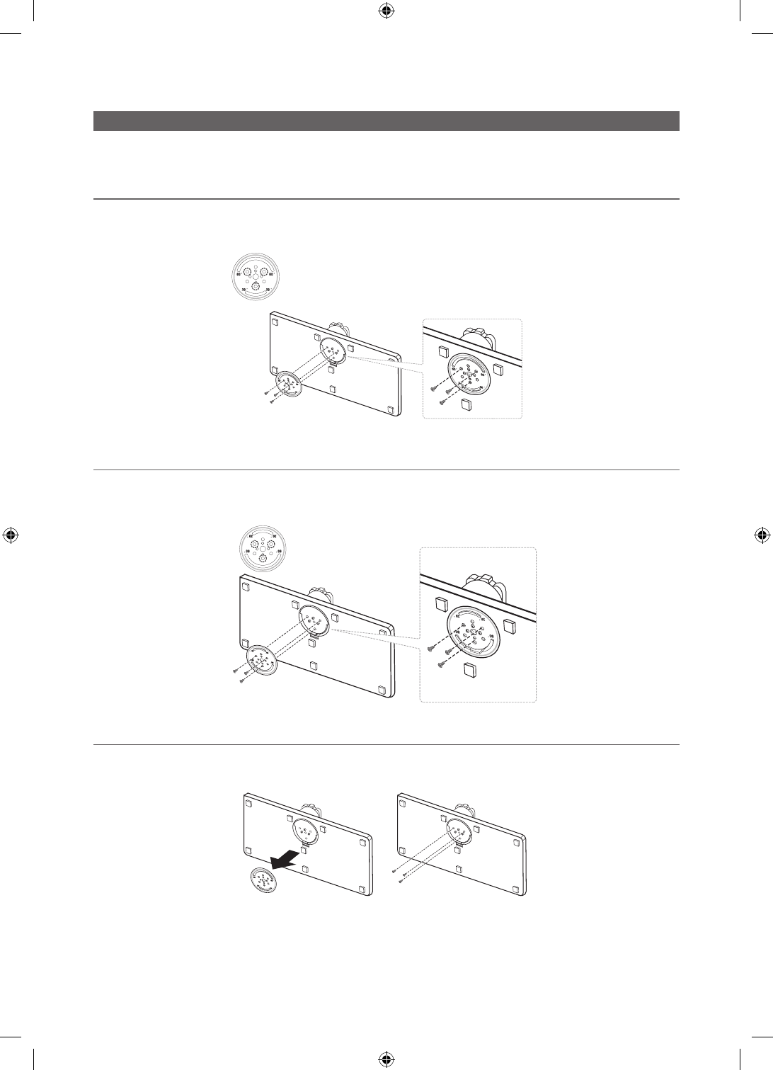
Assembling the swivel stand (40 inch TVs or larger)
The 40” and larger LED TVs have swivel stands. You can configure these stands so that the TVs swivel 20 degrees left and
right, 60 degrees left and right, or 90 degrees left and right using the BRACKET HOLDER SWIVEL.
¦20° swivel
To configure the TV so that it swivels 20° left and right, insert the prong on the bottom of the stand through the curved hole
in the Bracket Holder Swivel marked 20°. Then, fix the Bracket Holder Swivel to the stand using the three supplied screws as
shown to the left.
¦60° swivel
To configure the TV so that it swivels 60° left and right, insert the prong on the bottom of the stand through the curved hole
in the Bracket Holder Swivel marked 60°. Then, fix the Bracket Holder Swivel to the stand using the three supplied screws as
shown to the left.
¦90° swivel
To configure the TV so that it swivels 90° left and right, remove the Bracket Holder Swivel, and then screw the three supplied
screws into the stand as shown to the left.
[HC670_677_678-ZA]Install Guide-X0ENG.indd 6 2014-01-17 8:47:46
7
English
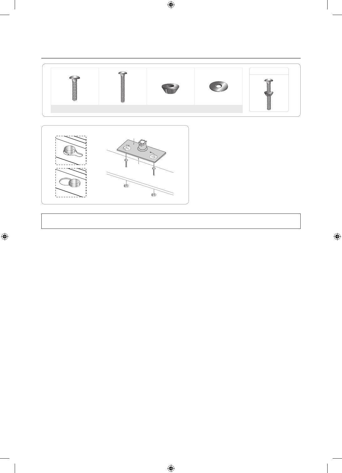
¦Hotel Mount Kit
Bolt + Nut
Short Bolt (2EA) Long Bolt (2EA) Nut (2EA) Washer (2EA)
Affix the stand to a flat surface such as a dresser
top, desk top, or entertainment center as shown.
[
WARNING: To prevent injury, you must attach this TV securely to the floor, a table, a dresser top, etc. with
the Hotel Mount Kit as described in these instructions.
Top
Bottom
[HC670_677_678-ZA]Install Guide-X0ENG.indd 7 2014-01-17 8:47:47
8
English
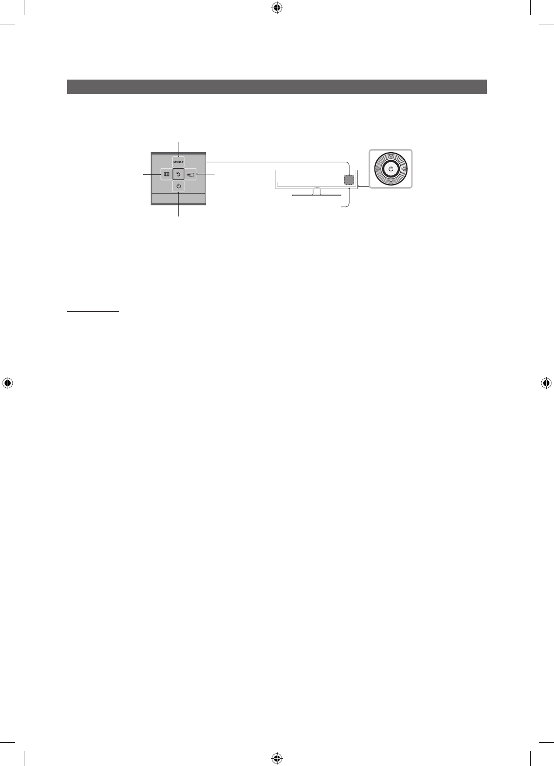
Using the TV's Controller
The TV’s Controller, a small joy stick like button on the rear right side of the TV, lets you control the TV without the remote
control.
TV Controller
The image is drawn
as if you are facing the
front side of the TV.
Power off
Function menu
Remote control sensor
Return
Selecting the
Media Play
Selecting the
Menu
Select a source.
✎
The product color and shape may vary depending on the model.
✎
To exit the menu, press the Controller for more than 1 second.
✎
When selecting a function by moving the controller backwards/forwards/left/right, be sure not to press up on the
controller. If you press up first, it will not operate correctly.
Standby mode
Your TV enters Standby mode when you turn it off and continues to consume a small amount of electric power. To be safe
and to decrease power consumption, do not leave your TV in standby mode for long periods of time (when you are away on
vacation, for example). It is best to unplug the power cord.
[HC670_677_678-ZA]Install Guide-X0ENG.indd 8 2014-01-17 8:47:47
9
English
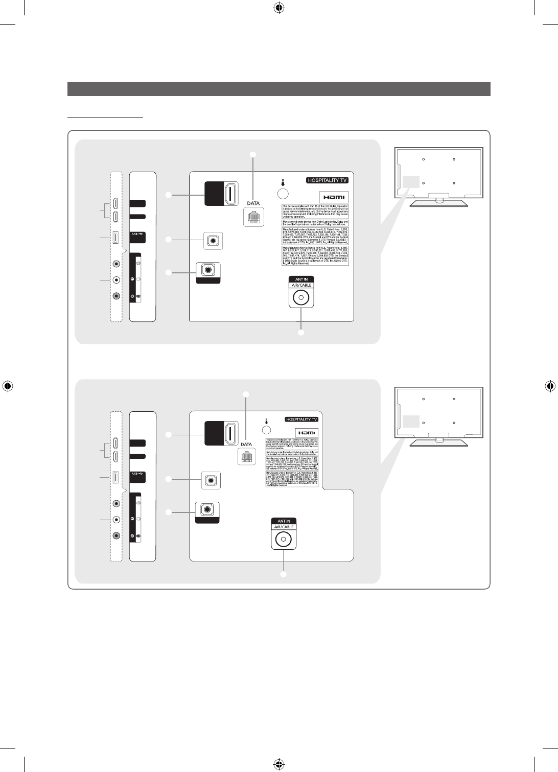
The Connection Panel
HC670/HC677 Model
- SIDE -
2
(5V 0.5A)
/ CLONING
3
HDMI IN 1
HDMI IN 2
(DVI)
1
HDMI IN 3
(ARC)
EX-LINK
1
4
AUDIO OUT
5
7
AV IN
AUDIO
VIDEO
- SIDE -
2
(5V 0.5A)
/ CLONING
3
HDMI IN 1
HDMI IN 2
(DVI)
1
HDMI IN 3
(ARC)
EX-LINK
1
4
AUDIO OUT
5
AV IN
AUDIO
VIDEO
7
6
6
40"/48" MODEL
28" MODEL
[HC670_677_678-ZA]Install Guide-X0ENG.indd 9 2014-01-17 8:47:47
10
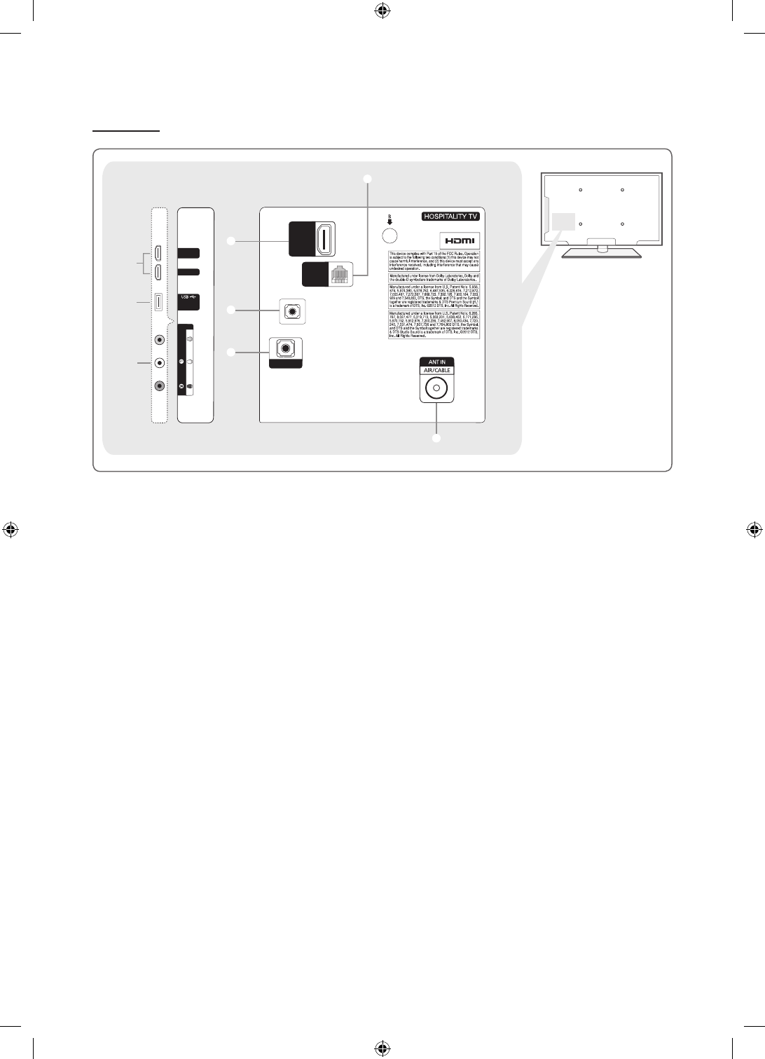
English
HC678 Model
- SIDE -
2
(5V 0.5A)
/ CLONING
3
HDMI IN 1
HDMI IN 2
(DVI)
1
HDMI IN 3
(ARC)
1
4
AUDIO OUT
5
AV IN
AUDIO
VIDEO
8
HDMI IN 3
(ARC)
GAME
CONTROL
DATA
EX-LINK
6
✎
Whenever you connect an external device to your TV, make sure that the TV and the device are turned off.
✎
When connecting an external device, match the color of the connection terminal to the cable.
1 HDMI IN 1, 2 (DVI), 3 (ARC) : Connects to the HDMI jack of a device with an HDMI output.
✎
No separate sound connection is needed for an HDMI to HDMI connection. HDMI connections carry both audio
and video.
✎
Use the HDMI IN 2 jack for a DVI connection to an external device. Use a DVI to HDMI cable or DVI-HDMI adapter
(DVI to HDMI) for the video connection and the DVI AUDIO IN jack for audio. Some DVI or HDMI devices may not or
should not need a DVI AUDIO IN connection for audio.
2 USB / CLONING
– Connector for software upgrades and Media Play, etc.
– Service connection.
3 VIDEO / L-AUDIO-R
– Connect a VIDEO cable to an appropriate external A/V device such a VCR, DVD, or Camcorder.
– Connect audio cables to "L-AUDIO-R" on your TV and the other ends to corresponding audio out jacks on the A/V
device.
4 EX-LINK : Connect this jack to the jack on the optional RJP (Remote Jack Pack). The RJP allows you to connect external
devices (Camcoders, PCs, DVD players, etc) easily.
5 AUDIO OUT : Connects to the audio input jacks on an Amplifier/Home Theater.
6 ANT IN or AIR/CABLE
– To view television channels correctly, the TV must receive a signal from one of the following sources:
– An outdoor antenna / A cable television system / A satellite receiver.
7 DATA
– Used to support data communication between the TV and the external SBB or STB.
– Connects using an RJ-12 type of plug.
8 GAME CONTROL DATA
– Used to connect the Lodgenet game controller in the Lodgenet system or support data communication between the TV
and the external SBB or STB.
– Connects using an RJ-12 type of plug.
[HC670_677_678-ZA]Install Guide-X0ENG.indd 10 2014-01-17 8:47:48
11
English
Using the TV's Controller
HOME
CONTENT
CH
LIST
ALARM
SLEEP CC
CHVOL
¢
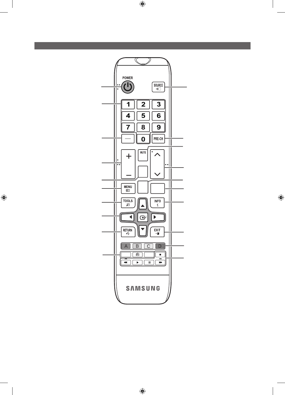
Turns the TV on and off. Display and select the available video
sources.
Return to the previous channel.
Change channels.
Use these buttons in Contents Home.
Exit the menu.
Press to display channel and TV information
on the TV screen.
SLEEP: Sets the Sleep Timer.
X
: Turns the 3D image on or off.
(Not available)
CC: Controls the caption decoder.
Cut off the sound temporarily.
Press to access channels directly.
Adjust the volume.
Display the channel list on the screen.
Display the main on-screen menu.
HOME: Display the REACH menu if REACH
has been downloaded to the TV.
Quickly select frequently used functions.
Return to the previous menu.
Use these buttons in a specific feature.
Select on-screen menu items and change
menu values.
Press to select additional digital channels
being broadcast by the same station. For
example, to select channel ‘54-3’, press
‘54’, then press '-' and ‘3’.
Use these buttons according to the directions on
screen (to perform a function, display a screen, etc.).
[HC670_677_678-ZA]Install Guide-X0ENG.indd 11 2014-01-17 8:47:48
12
English
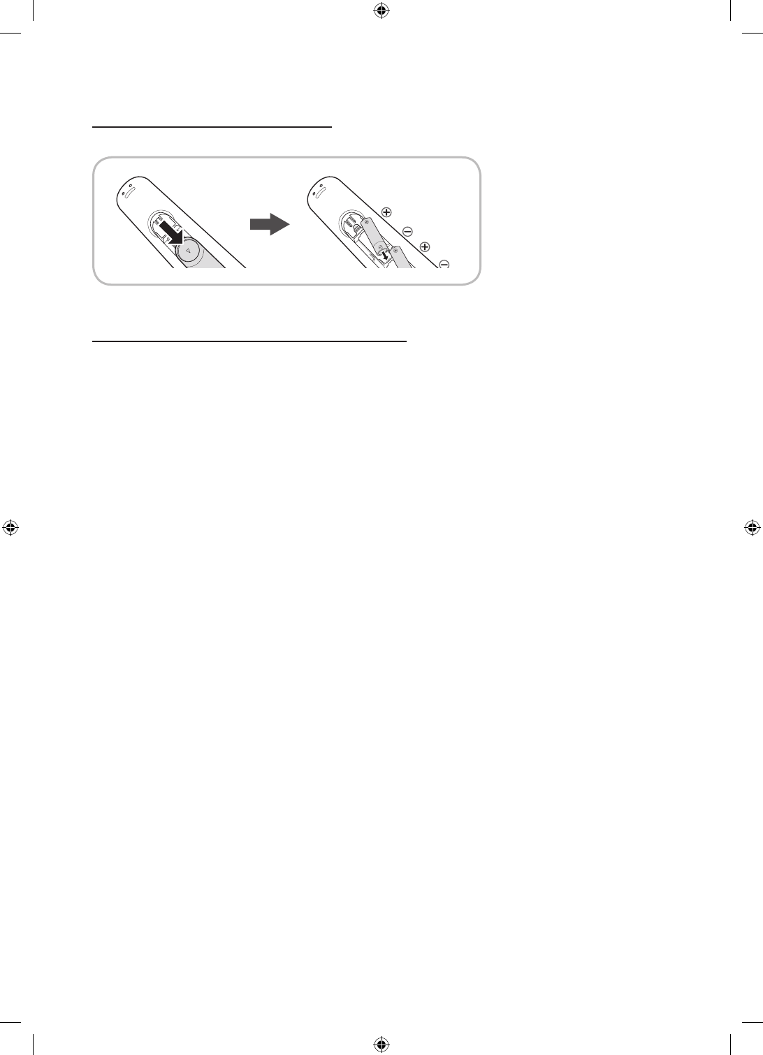
Installing the batteries (Battery size: AAA)
Rear of the Remote
✎
After you have installed the batteries, use a screwdriver to screw in the screw that holds the battery cover closed.
Installing Batteries into the Remote (battery size: AAA)
Match the polarity of the batteries to the symbol in the batter compartment.
✎NOTE
•Use the remote control within 23~33 feet of the TV.
•Bright light may affect the performance of the remote control. Avoid using near fluorescent lights or
neon signs.
•The color and shape of the remote may vary depending on the model.
[HC670_677_678-ZA]Install Guide-X0ENG.indd 12 2014-01-17 8:47:48
13
English
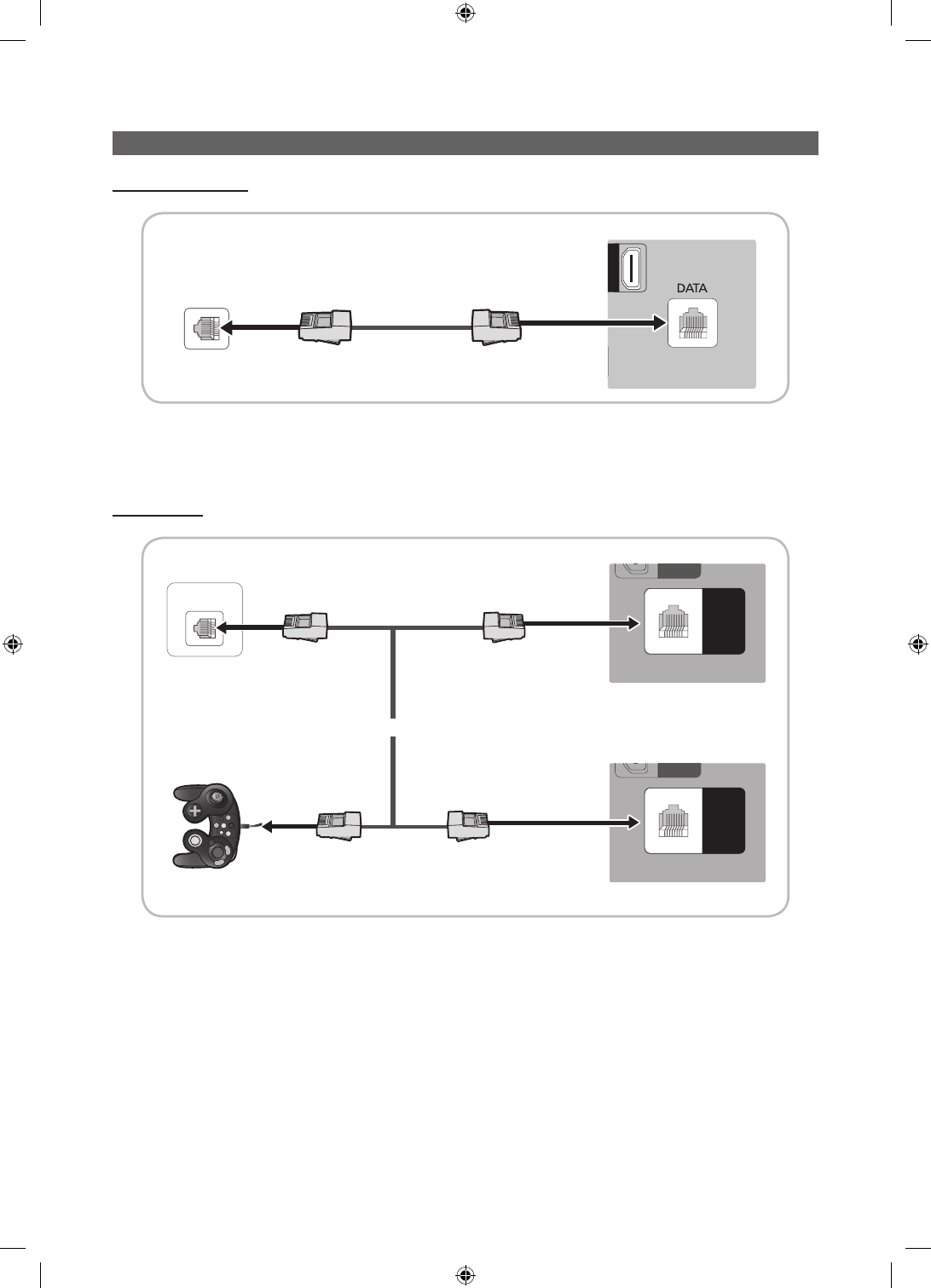
Connecting the TV to the Lodgenet game controller or a STB of a SI vendor
HC670/HC677 MODEL
N 3
)
TV Rear Panel
Data Cable
ETH MODEM
1. Connect the DATA jack of the TV to the ETH MODEM jack of the STB (SBB) with the Data cable.
✎
The "ETH MODEM" jack name that you connect the Data Cable to may differ depending on the SBB or STB type.
HC678 MODEL
GAME
CONTROL
DATA
G
AM
E
C
ONTRO
L
D
ATA
GAME
CONTROL
DATA
GAME
CONTROL
DATA
G
AM
E
C
ONTRO
L
D
ATA
GAME
CONTROL
DATA
ETH MODEM
TV Rear Panel
Data Cable
1. Connect the LodgeNet game controller to the TV's GAME CONTROLLER/DATA jack of the TV.
2. Connect the GAME CONTROLLER/DATA jack of the TV to the ETH MODEM jack of the STB (SBB) with the data cable.
✎
The “ETH MODEM” jack name that you connect the Data Cable to may differ depending on the SBB or STB type.
TV Rear Panel
or
Data Cable
Data Cable
Game Controller
[HC670_677_678-ZA]Install Guide-X0ENG.indd 13 2014-01-17 8:47:49
14
English
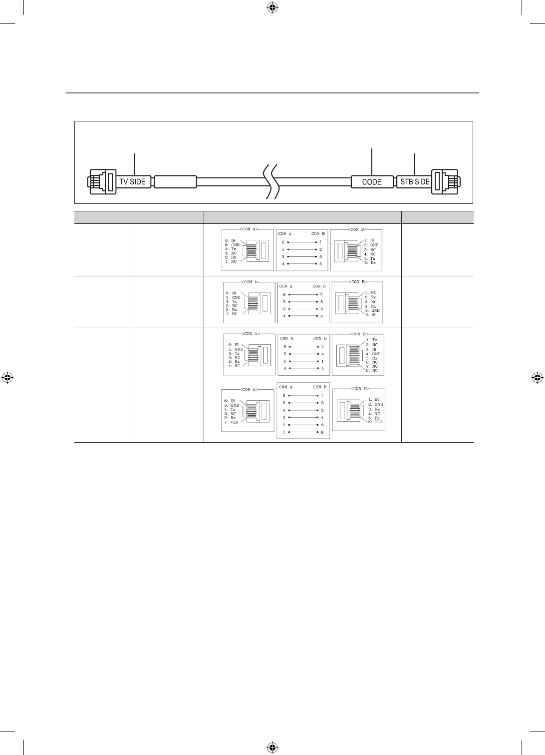
¦List of SI Vendors and Compatible Data Cables Supplied with the TV
yConfirm you are using the correct data cable for your SI vendor. Refer to the code label on the data cables.
yContact your nearest dealer or your SI Vendor to buy the data cable not included in the TV.
Confirm the code on the
Code Label
Note the labeled end. Note the labeled end.
SI Vendor Cable code Pin assign Remark
Samsung
OCC
Enseo
Guest-Tek
BN39-00865B
Only Provided with
NB670 and NB677
models.
NXTV BN39-01011B
nStreams BN39-01110A
MTI BN39-01011C Only Provided with
NB677 models.
[HC670_677_678-ZA]Install Guide-X0ENG.indd 14 2014-01-17 8:47:49

15
English
¦Connecting the Audio Output to an Audio Amplifier
EX-LINK
EX-LINK
AUDIO OUT
AUDIO IN
TV Rear Panel
Audio
Amplifier
1 Stereo cable
1. Connect the AUDIO OUT port of the TV to the Audio In port of an audio amplifier with a stereo cable.
[HC670_677_678-ZA]Install Guide-X0ENG.indd 15 2014-01-17 8:47:49
16
English
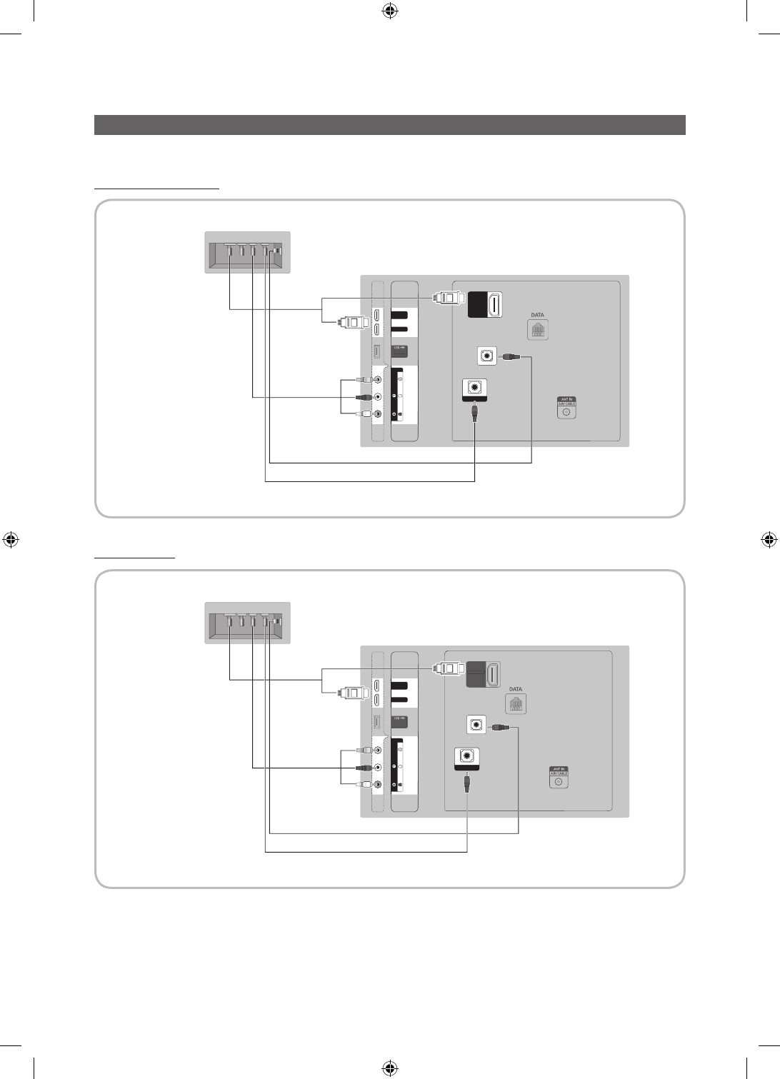
Connecting the RJP (Remote Jack Pack)
Connect the input jacks on the TV to the RJP. The RJP lets guests connect audio and video sources to the TV.
HC670/HC677 Model
HC678 Model
TV Rear Panel
(5V 0.5A)
/ CLONING
HDMI IN 1
HDMI IN 2
(DVI)
HDMI IN 3
(ARC)
AV IN
AUDIO
VIDEIO
EX-LINK
AUDIO OUT
(
5V 0.5A
)
/
CL
O
NIN
G
HDMI IN 1
HD
MI IN
2
(
DVI
)
()
HDMI IN 3
3
(
ARC
)
AV I
N
A
U
DI
O
VIDEI
O
EX
-
LINK
A
UDI
O
O
UT
USB HDMI S-VIDEO RCA AUDIO/PC
RS/232
HDMI IN 1
HDMI IN 2
(DVI)
AV IN
AUDIO
VIDEO
HDMI IN 3
(ARC)
EX-LINK
AUDIO OUT
2 Video / Audio
Cable
1 PC Audio cable
RJP Rear
4
3 HDMI Cable
TV Rear Panel
(5V 0.5A)
/ CLONING
HDMI IN 1
HDMI IN 2
(DVI)
AV IN
AUDIO
VIDEIO
HDMI IN 3
(ARC)
EX-LINK
AUDIO OUT
(5V 0.5A
)
/
CL
O
NIN
G
HD
MI IN
1
HD
MI IN
2
(DVI)
()
AV IN
A
U
DI
O
VIDEI
O
HDMI IN 3
3
(ARC)
EX
-
LINK
A
UDI
O
O
UT
USB HDMI S-VIDEO RCA AUDIO/PC
RS/232
HDMI IN 1
HDMI IN 2
(DVI)
AV IN
AUDIO
VIDEO
EX-LINK
AUDIO OUT
2 Video / Audio
Cable
1 PC Audio cable
RJP Rear
4
3 HDMI Cable
[HC670_677_678-ZA]Install Guide-X0ENG.indd 16 2014-01-17 8:47:50
17
English
1. Connect the AUDIO OUT port of the TV to the PC/AUDIO port of the RJP.
2. Connect the AV IN VIDEO/L-AUDIO-R ports of the TV to the RCA port of the RJP.
3. Connect one of the HDMI IN ports of the TV to the HDMI port of the RJP.
4. Connect the EX-LINK port of the TV to the RS/232 port of the RJP.
✎
This Samsung TV is compatible with the Tele Adapt TA-7610 RJP only.
yRJP (Remote Jack Pack): The RJP is a hardware module that has different Audio Video inputs (A/V, Audio, PC
and HDMI) and corresponding outputs. The corresponding outputs are connected from the RJP to the TV. The RJP
communicates with the TV via RS232. The RJP communicates with the TV by sending messages regarding Active/Inactive
sources.
– A group of hotel menu items let you assign numbered priorities to the jacks of the RJP. (See page 19). 1 is the highest
priority and 3 is the lowest. When a guest connects external sources to the RJP jacks, the TV will automatically switch
between sources based on the priority you have assigned them in the Menu. For example, lets say AV is set to 1
and HDMI to 2. If a guest has attached a device to the HDMI jack, and then plugs a device into the AV jack, the TV
automatically switches to the device plugged into the AV jack (the jack with the higher priority). Note that a guest can
also switch between devices manually by pushing a button on the RJP.
✎
When you set up the RJP, connect the RJP to HDMI 1, 2, or 3 or AV 1 or 2.
yTo reset the RJP to its factory default state, press the AV and HDMI buttons simultaneously for 10 seconds. When all
button LEDs blink 5 times, the RJP reset is complete.
yThe RJP will automatically turn off any LEDs after 5 minutes to avoid unnecessary light pollution in the hotel room. The
LEDs that were turned off will turn on again if the guest touches any of the buttons and the 5 minute timer will restart. If the
guest then touches another source button, the TV will change to the selected source and the corresponding LED will be lit.
yAfter an RJP Reset or a TV Power OFF/ON, it takes approximately 10 seconds to establish communications between the
TV and the RJP.
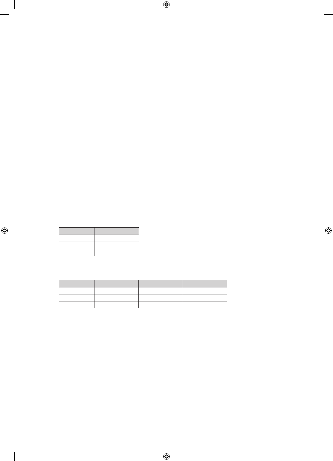
yThe following table shows the approximate time in seconds it takes to switch from the TV to an input source, based on
assigned or default priorities.
✎
Scenario 1 : When no inputs are connected.
Source To Connect
AV 2 Sec
PC 0.7 Sec
HDMI 3.9 Sec
✎
Scenario 2: When two or more inputs are connected to the RJP and one of the input sources is disconnected and
then reconnected.
Source Disconnect To Connect Total
AV 4.5 Sec 2 Sec 6.5 Sec
PC 0.7 Sec 0.7 Sec 1.4 Sec
HDMI 3.9 Sec 3.9 Sec 7.8 Sec
✎
An example: If the RJP has all its live sources (AV, PC, and HDMI) connected, AV has been assigned the highest
priority, the RJP is in HDMI mode, and a guest removes and reconnects the AV source, the minimum time required
to switch to the AV source is 6.5 seconds.
yTo play audio devices (Ipods, MP3 devices, etc.) through the RJP, you must turn Music Mode AV in the menu on. (See
page 20)
yMusic mode in the TA-7610 RJP is supported by the AV jack only. HDMI Music mode is available for the Guestlink RJP
only.
[HC670_677_678-ZA]Install Guide-X0ENG.indd 17 2014-01-17 8:47:50
18
English
Setting the Hotel Option Data
To let you control how the TV functions when in Hotel mode, the TV has two Hotel mode menus, the Stand-alone mode menu
and the Interactive mode menu. The menu items that differ between the menus are listed below.
Menu items in the Stand-alone mode only:
– SI Vendor : Smoovie
– REACH Server and its submenus.
Menu items in the Interactive mode only:
– SI Vendor: Samsung and other vendors.
All other items appear in both menus
To access the menus, press MUTE → 1 → 1 → 9 → ENTER
E
on your Samsung remote.
After a menu appears, follow these general directions to navigate and change values:
– Use the Up and Down arrow buttons on the Samsung remote to move from menu item to menu item.
– Press the Enter or Left or Right arrow buttons to select a menu item. The screen displays that menu item only.
– Press the Left or Right arrow button to change a value. The Right arrow button increases numerical values. The Left
arrow button decreases numerical values.
– When the screen is displaying one menu item, you can press the Up or Down arrow button to display the next or
previous menu item.
– Press the RETURN or MENU button to exit the current menu item and go to a higher menu level or the Main menu.
– To exit a Hotel mode menu, turn off the TV, and then turn it on again. Any changes you made are saved except changes
to SI Vendor. For changes to SI Vendor, you must turn the TV off, wait until the Standby light glows steadily, then unplug
the TV, wait for the Standby light to go off, and then plug the TV in again.
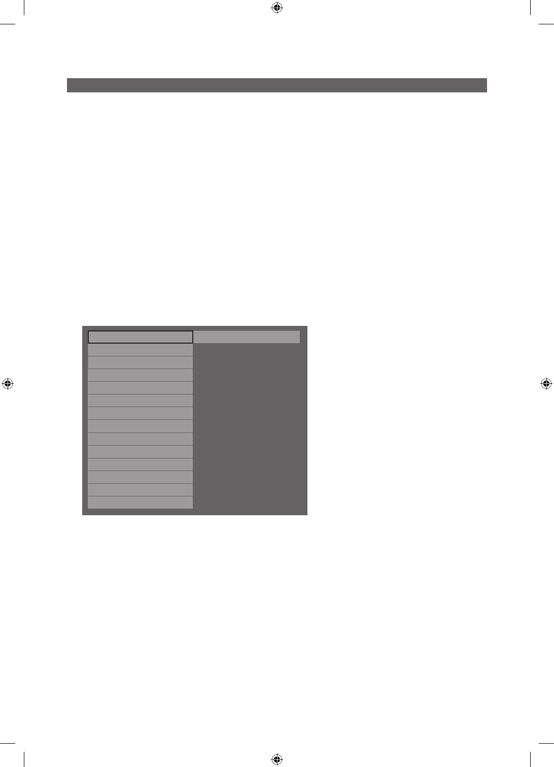
Hospitality Mode Standalone System
SI Vendor OFF
Power On
Channel
Menu OSD
Clock
Music Mode
Remote Jack Pack
External Source
Eco Solution
Logo/Message
REACH Solution
Security
DRM
Above: The Hotel mode menu.
To change menus, follow these steps:
1. Highlight the Hospitality Mode menu item in the top left corner of the menu.
2. Press the left or right arrow button on the Samsung remote. Only the Hospitality Mode menu item is displayed.
3. Press the left or right arrow button to change the Hospitality Mode item from Standalone to Interactive or from Interactive to
Standalone.
4. Press the Return or Menu button on the remote. The entire menu re-appears with your selection displayed in the Hospitality
Mode field.
✎
After you have set the values in one TV, you can clone those values to multiple TVs. See USB Cloning on page 25.
[HC670_677_678-ZA]Install Guide-X0ENG.indd 18 2014-01-17 8:47:50
19
English
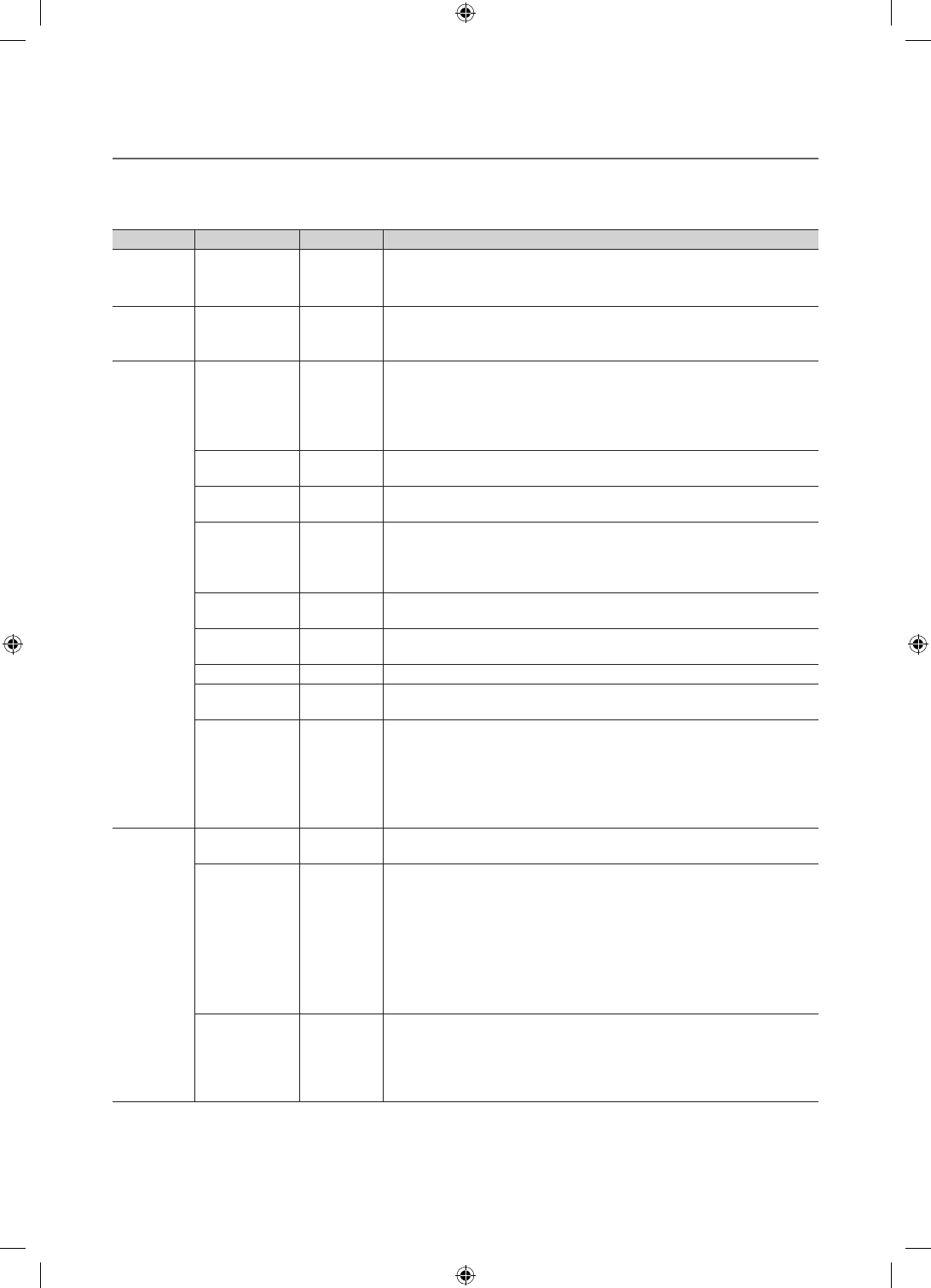
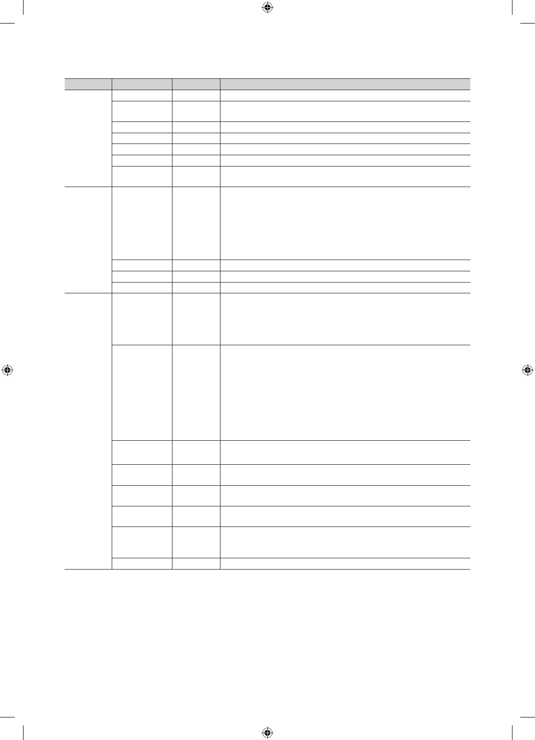
¦Menu Items
To Enter this menu: Press the MUTE → 1 → 1 → 9 → ENTER
E
buttons in order.
To exit from this menu : Power Off (or Power Off and unplug if you have changed SI Vendor), and then turn on again. Any
changes you made are saved.
Menu Item initial Value Description
Hospitality
Mode Hospitality Mode Standalone
Select the Hospitality mode.
yStandalone mode: TV works alone, without an SI STB or SBB
yInteractive mode: TV works with an SI STB or SBB
SI Vendor SI Vendor OFF
yInteractive mode : Samsung / OCC / MTI / Nstreams / NXTV / Enseo /
Cardinal / Guestek / Seachange / EBL
yStand-alone mode : OFF / Smoovie
Power On
Power On
Channel Last Saved
Set the default values that will be applied when the TV is turned on.
yUser Defined : Lets you set Power On Channel and Channel Type
manually. See Power On Channel and Channel Type below.
yLast Saved : If you select this item, when the TV is turned on, it displays
the channel it was displaying when it was turned off.
Power On
Channel Num … When the TV is turned on, it switches automatically to this channel.
Power On
Channel Type … ySelect channel band : AIR (analog air band), DTV (digital air band), CATV
(analog cable band), CDTV (digital cable band)
Power On
Volume Last Saved
yUser Defined : Lets you set the Power On Volume manually. See Power
On Volume below.
yLast Saved : When the TV is turned on, it returns to the volume that had
been set when the power had been turned off.
Power On
Volume Num … The TV turns on with this Volume Level in Stand Alone Hospitality mode.
Min Volume 0 The minimum Volume Level the user can set in Stand Alone Hospitality
mode.
Max Volume 100 The maximum Volume Level the user in Stand Alone Hospitality mode.
Power On
Source TV Select the input source the TV displays when turns on.
Power On
Option Last Option
Determines the TV's state when power returns after a power failure or after
you have unplugged the TV and then plugged it in again.
yLAST OPT : Returns to its last Power state. If it was in Stand-by, it
returns to Stand-by. If it was on, it turns on.
yPower On : When the power returns, the TV turns on.
yStandby : When the power returns, the TV enters the Standby mode.
Channel
Channel Setup Gives you direct, immediate access to some of the Channel menu functions
on the user Channel menu such as Auto Program, Antenna selection, etc.
Channel Editor
The Channel Editor lets you edit the channels stored in the TV's memory.
Using Channel Editor you can:
•Changethechannelnumbersandnames,andsortthechannelsinyour
desired channel number order.
•Applythevideomutetochannelsyouselect.Thevideomuteblanksout
the video from a channel and outputs only the sound while displaying a
speaker icon on the screen.
The Channel Editor also lets you view information about each channel easily,
without your having to display each channel directly.
Dynamic SI ON
yOn : Check the DTV Program channel number. (If Dynamic SI is On, it is
not availale to edit DTV channels in Channel Editor.)
yOff : Does not check the DTV Program channel number. (If Dynamic
SI is Off, it is available to edit DTV channels in Channel Editor, but
additional DTV channel program number update is not supported.)
[HC670_677_678-ZA]Install Guide-X0ENG.indd 19 2014-01-17 8:47:50

20
English
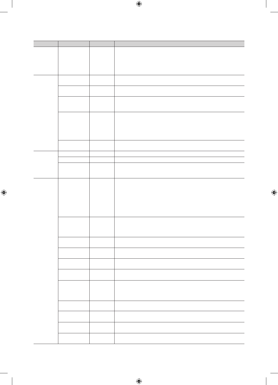
Menu Item initial Value Description
Menu OSD
Picture Menu
Lock OFF Enable or disable the Picture Menu.
Menu Display ON yOn : The Main Menu is displayed.
yOff : The Main Menu is not displayed.
Panel Button
Lock Unlock
Turning the front panel (local key) operations on/off.
yUnlock : Unlocks all panel keys.
yLock : Locks all panel keys.
yOnlyPower : Locks all panel keys except the Power panel key.
yMenu/Source : Locks the Menu and Source panel keys.
Home Menu
Display …OFF:The Home Menu is not displayed.
ON:The Home Menu is displayed.
Home Menu
Editor yHome Menu is displayed.
Home Menu
Auto Start ON OFF:The Home Menu is Auto Start.
ON:The Home Menu is not Auto Start.
Clock Local Time Manual
Select the way to update clock data.
Use clock data from a DTV channel to set the clock automatically or set the
clock manually when the TV is in stand-alone mode.
Music
Mode
Music Mode AV OFF
Allows music output from an mp3/audio player connected to an AV Input
Source on the TV. When on, you can hear sound from the player
through the TV whether there is a video signal or not. Also mutes the video
so the TV does not display a picture when a guest is playing
music. The TV's backlight, however, remains on.
Music Mode
Backlight OFF When set to Off, the TV's backlight is turned off entirely when a guest uses
the Music mode. To save energy, set to Off.
Remote
Jack Pack
Priority AV 1 If the jack priority is set, the corresponding source is automatically set when
a jack is inserted according to the jack priority
Priority HDMI 2 If the jack priority is set, the corresponding source is automatically set when
a jack is inserted according to the jack priority.
AV Option AV Select RJP AV Source (Source selection depends on Model).
HDMI Option HDMI 1 Select which HDMI source of the TV is connected to the RJP jack. (HDMI1/
HDMI2/HDMI3)
HDMI Music
Mode OFF
Allows music output from an mp3/audio player connected to an HDMI Input
Source. When on, you can hear sound from the player through an HDMI
input of the RJP whether there is a video signal or not. (This option is only
compatible with the Guest link RJP.)
External
Source
USB Pop-up
Screen Default
When a USB device is connected to the TV :
yDefault : A popup window appears.
yAutomatic : Opens the USB contents menu automatically.
yDisable : Neither the popup window nor the menu appears.
External Source
Banner ON
If set to On, the TV displays the External Source Banner (information) when
you change the TV source to another external input, press the Info key, or
turn the TV on.
yOn : The External Source information is displayed on the TV screen.
yOff : The External Source information is not displayed on the TV screen.
Auto source OFF
yOn : When an external input source is connected to the TV, the TV
identifies the input source, and then automatically switches to that input
source.
yOff : Auto Source function is Off.
Anynet+Return
Source
Power On
Src
Select the return TV source after stopping an Anynet+(HDMI-CEC)
connection. (This fuction is especially useful for the Guestlink RJP.)
[HC670_677_678-ZA]Install Guide-X0ENG.indd 20 2014-01-17 8:47:50
21
English
Menu Item initial Value Description
Eco
Solution Energy Saving Off
Adjusts the brightness of the TV to reduce power consumption.
yOff: Turns off the energy saving function.
yLow: Sets the TV to low energy saving mode.
yMedium: Sets the TV to medium energy saving mode.
yHigh: Sets the TV to high energy saving mode.
Logo/
Message
Welcome
Message OFF Displays a the Welcome Message for 5 seconds when the TV turns On.
Edit Welcome
Message Edits the Welcome Message.
Hospitality Logo OFF
Turns the Hospitality logo feature On or Off, If On, when the TV is turned
on, the Logo is displayed, before the signal from the initial source, for the
amount of time set in "Logo Display Time".
Hospitality Logo
DL …
Downloads the Hospitality logo.
Hospitality logo file requirements:
yBMP or AVI files only.
yMax file size : BMP - 960 X 540. AVI - 30MB.
yThe file can only be named samsung.bmp or samsung.avi.
Logo Display
Time … Hospitality Logo Display Time (3/5/7 seconds).
Cloning
Clone TV to USB … Clone the current TV options to a USB memory device.
Clone USB to TV … Clone the saved TV options on a USB memory device to the TV.
Setting Auto
Intialize OFF
If you set Setting Auto Initialize to On, and the TV's power is turned off and
on, the guest side menu items are restored to their cloned values. See page
29.
REACH
Server
REACH Server
Update Time 1hour
Lets you set when data such as updated SW, cloning files, and S-LYNC
REACH contents is downloaded from the REACH server to the TV :
y1hour : Every hour
y2hour : Every 2 hours
y12:00 am : every 12:00 a.m.
y12:00 pm : every 12:00 p.m.
y2:00 pm : every 2:00 p.m."
REACH Update
Immediate OFF
yOn : Whenever the TV enters standby mode (the power cord is plugged
in and the power is off), the REACH data is updated on the TV.
yOff : The REACH data is only updated on the TV at the REACH server
update time.
REACH Server
Channel 87 Assign a DTV channel number to carry the update REACH data. This
channel number must be the same as the number set on the Reach server.
REACH Server
Version 0000 Displays the current REACH data version.
REACH Server
Group ID All Select the group ID of the REACH server. (Refer to the REACH server
manual for more details)
REACH OFF On : The S-LYNK REACH menu is displayed.
Off : The S-LYNK REACH menu is not displayed.
Backgroud TV
Sound ON
On : The TV sound of the current TV source is continuously outputted even
when the S-LYNK REACH menu is displayed.
Off : The TV sound of the current TV source is stopped when the S-LYNK
REACH menu is displayed.
IPG Room Type Default Selects the IPG room type of the REACH server. (Refer to the REACH server
manual for the more information.)
TICKER OFF yOn : The TICKER content is displayed.
yOff : The TICKER content is not displayed.
Applite OFF yOn : The Applite content is displayed.
yOff : The Applite content is not displayed.
Room Number
Setting Setting Room Number.
[HC670_677_678-ZA]Install Guide-X0ENG.indd 21 2014-01-17 8:47:51
22
English
Menu Item initial Value Description
Security
Password Input Input Password 00000000.(HC678 model none)
Password
Setting … Set new Password.(HC678 model none)
Password Reset … Reset Password to 00000000.(HC678 model none)
Security Mode … Security Mode ON or OFF.(HC678 model none)
USB … USB Disable or Enable.(HC678 model none)
HDMI … HDMI Disable or Enable.(HC678 model none)
TTX Security … TTX: manual clock setting (with updating from TTX data).(HC678 model
none)
DRM
DRM Mode Pro:idiom
Configures CAS support. Applies to only the NB673, NB677, and NB678
models.
OFF : Turns off CAS support.
LYNK DRM : Select to turn on S-LYNK DRM CAS support only.
Pro:idiom : Select to turn on Pro:Idim CAS support only.
LYNK DRM,PI : Select to have the TV support S-LYNK DRM CAS and
Pro:Idiom CAS.
PI AES Data 0xD279 Displays the current state of Pro:Idion AES
PI AES Log OFF
View PI AES Log …
Service
Self Diagnosis
for TV
Lets you check the state of the TV picture and sound.
•PictureTest:Usetocheckforpictureproblems.Iftheproblemappearsin
the test picture, select YES, and then follow the directions on the screen.
•SoundTest:Usetocheckforsoundproblems.Iftheproblemoccurs
during the test, select YES, and then follow the directions on the screen.
Self Diagnosis
for HTV
Lets you check the state of Pro:Idiom and its communication with the
SI STB or SBB. If you have any problems with the Pro:idiom encryption
channel or the communications with the SI STB or SBB, use this diagnosis
function. If Pro:Idiom DTV Channel Key Loss appears to have failed and
the Pro:Idim encryption channel has failed to play content, first check the
broadcasting systems related to Pro:Idiom encryption. If your broadcasting
system does not have a problem, contact Samsung Service. If STB SI
Vendor Setting appears to have failed and communication with the SI STB
or SBB has failed, first check your SI STB or SBB. If your SI STB or SBB
does not have a problem, contact to Samsung Service.
SW Upgrade Lets you upgrade the TV SW with a USB memory stick. See Page 32.
Service Pattern OFF Lets you check the state of the TV picture by displaying picture test
patterns. Press the Menu button to turn off the test patterns and exit.
ATV Cable AGC
Gain Default Lets you control the AGC gain of the analog cable channels. Don't change
the default value unless problems occur.
DTV OpenCable
AGC Gain Default Lets you control the AGC gain of the digital cable channels. Don't change
the default value unless problems occur.
Sound Bar Out OFF
ON: TV speaker sound will be mute. Sound will come out through HDMI.
You must connect the Sound Bar to hear the sound.
OFF: Sound will come out through TV speakers normally.
TV reset Returns all settings on the TV to their factory defaults.
✎
REACH (Remote Enhanced Active Control for Hospitality) is a professional, interactive remote controller that lets you
deliver TV firmware updates, cloning data, channel mapping changes, S-LYNK REACH contents, and TICKER contents
through RF DTV to several hundred hospitality TVs simultaneously. The REACH functions are available only in stand-
alone mode. The REACH Server is sold separately. Refer to the REACH server manual enclosed with the REACH server
product for more operating information.
[HC670_677_678-ZA]Install Guide-X0ENG.indd 22 2014-01-17 8:47:51
23
English
¦Using the Football Mode
Foodball Mode t
✎
MENUm → Applications → Football Mode → ENTER
E
This mode provides optimized condition for watching sports games.
ya (Zoom): Pause playback and divide the picture into 9 parts. Select a part to zoom it in. Press this button again to
resume.
✎
If you turn the TV off while watching Football Mode, the Football Mode will be disable.
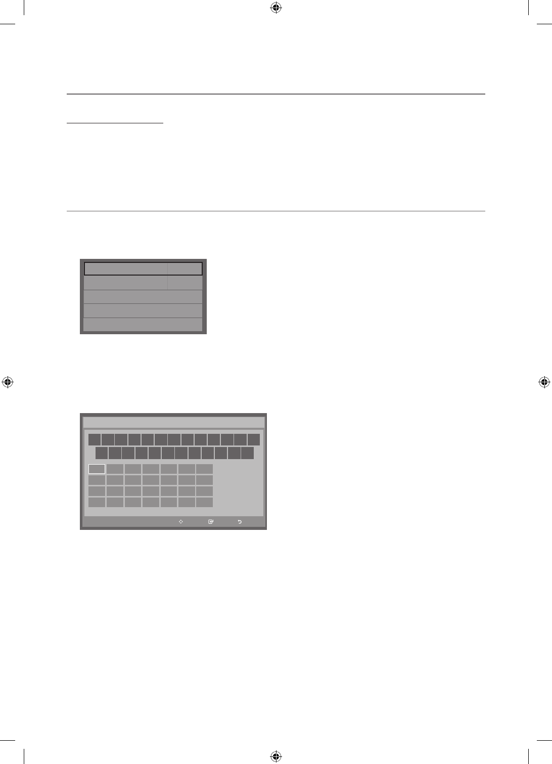
¦Welcome Message
The Welcome Message feature displays a custom message on the TV every time it is turned on.
– Welcome message settings are in the Hotel Option Menu.
– Set Welcome Message to ON to display the message when the TV is powered on.
Welcome Message OFF
Edit Welcome Message
Hospitality Logo OFF
Hospitality Logo DL ...
Logo Display Time ...
– You can make the Welcome Message up to 25 characters long and edit it in the Hotel Service menu.
– Welcome Message supports the following characters:
✎
Capital Letters from A to Z.
– You can edit the Welcome Message by using the remote's navigation, color, and Enter buttons in the “Edit Welcome
Message” OSD (See the illustration below.)
Move Enter Return
a
b
{
}
Move to Left
Move to Right
Leave Black
Done
A B C D E F G
H I J K L M N
O P Q R S T U
V W X Y Z
W E L C O M E T O O U
R H O T E L _
Edit Welcome Message
Below are the general directions for navigating and changing letters on the Edit Welcome Message screen:
– Press the
a
button on the remote to move to the left in the message.
– Press the
b
button to move to the right.
– After you have selected a position in the message, use the arrow buttons on your remote to select a letter in the
alphabet below the message.
– Press Enter to place a letter into the position you selected.
– Press the
{
button to erase a letter in a position or enter a blank.
– Press Return or the
}
button to exit.
[HC670_677_678-ZA]Install Guide-X0ENG.indd 23 2014-01-17 8:47:51
24
English
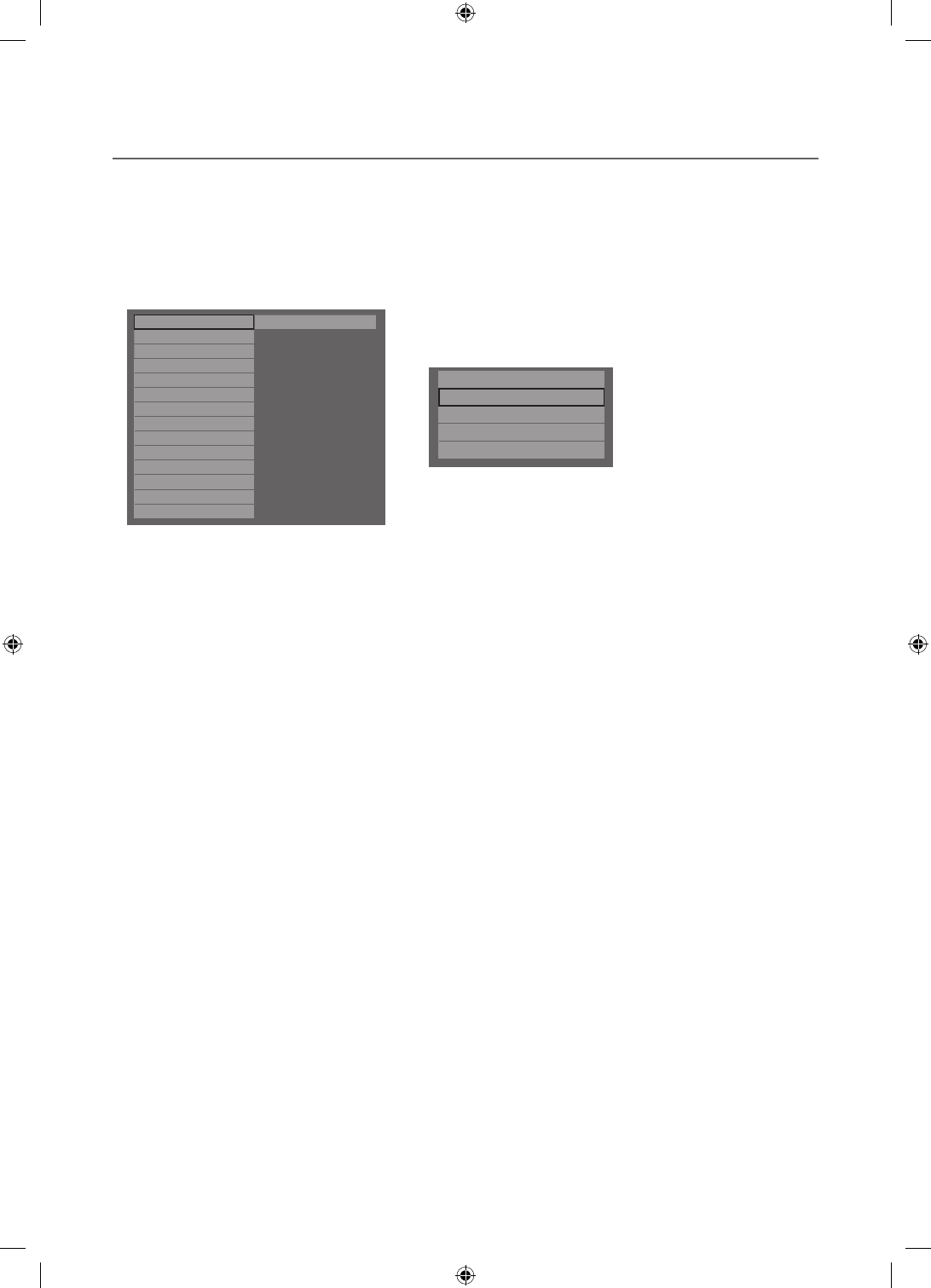
¦Hotel Logo
The Hospitality Logo function displays the Hotel's picture image when the TV is powered on.
– Hospitality Logo settings are the Hotel mode menus.
– The Logo Download and Logo Display Menu items are enabled when you turn the Hospitality Logo option on.
– If there is a logo image stored in memory and the Hospitality Logo option is on, the Hospitality logo is displayed when
the TV is turned on.
– The Hospitality logo is not displayed when the Hospitality found Logo option is off, even if the logo image has been
loaded into the TV.
Hospitality Mode Standalone System
SI Vendor OFF
Power On
Channel
Menu OSD
Clock
Music Mode
Remote Jack Pack
External Source
Eco Solution
Logo/Message
REACH Solution
Security
DRM
r
Welcome Message ON
Edit Welcome Message
MessageHospitality Logo ON
Hospitality Logo DL -
Logo Display Time -
yHospitality Logo
– This option lets you choose whether the Hospitality Logo image is displayed or not.
– Initial value is OFF.
– Can be set to OFF or ON.
– When set to ON, the Logo Download and Logo Time Display menu items become accessible.
yLogo Download
– This option lets you download the logo image to the TV’s memory from a USB device.
– A wait message appears while the image is being copied to the TV.
– A "completed" message appears when the copy operation finishes successfully.
– The word "failed" appears if the copy operation was unsuccessful.
– No USB appears if no USB device is connected.
– No File appears if there is no file to copy on the USB device or the file is in the wrong format (must be a BMP or AVI
file). If No File appears and there is a logo file on the USB device, check the file format.
yLogo File Format
– The TV supports only BMP and AVI format.
– The file name must be samsung.bmp or samsung.avi.
– The maximum resolution of the BMP format is 960 x 540.
– The maximum file size for AVI format is 30MB.
– The TV does not change the size or scale of the image.
[HC670_677_678-ZA]Install Guide-X0ENG.indd 24 2014-01-17 8:47:52
25
English
¦USB Cloning
The USB Cloning function lets you download user-configured settings (Picture, Sound, Input, Channel, Setup, and Hotel
Setup) from one TV to a USB device, and then upload these settings from the USB device to other TV sets. This lets you
create a standard array of settings and distribute that standard array to all the TVs in your facility.
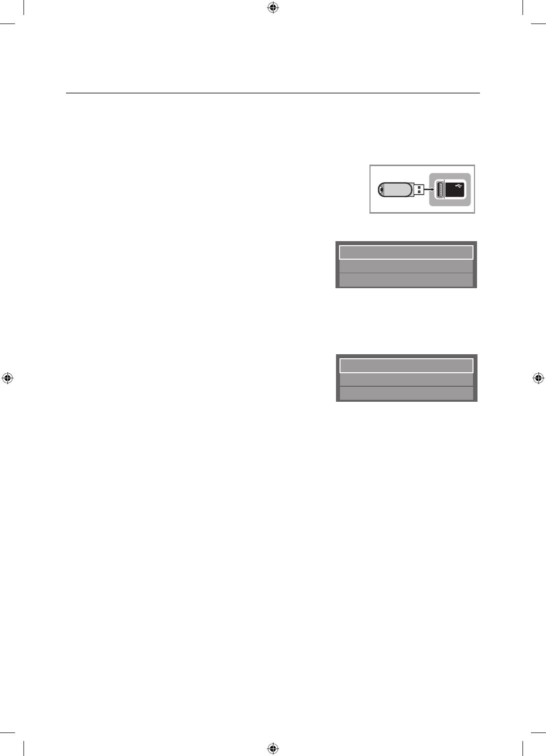
yCloning from TV to USB: Copies stored menu settings from a TV to a USB device.
1. Insert a USB drive into the USB port on the rear of the TV
2. Enter the hotel option menu by pressing these buttons in order. MUTE → 1
→ 1 → 9 → ENTER
E
3. Press the ▲ or ▼ button to select Clone TV to USB, and then press the
ENTER
E
button.
4. The message Clone TV to USB is displayed. Press the ENTER
E
button.
5. The TV displays one of the following messages:
▪In Progress: Copying data to USB.
▪Completed: Copy operation was successful.
▪Failed: Copy operation was not successful.
▪No USB: USB is not connected.
The clone folder will be labeled T-NVTF6AKUCB.
✎
The cloned values include the values on the Guest side menu
(brightness, picture size, contrast, etc.) and the Hotel side menu.
(5V 0.5A)
/ CLONING
USB
Clone TV to USB
Clone USB to TV
Setting Auto Initialize OFF
Cloning from USB to TV: Copies menu settings from a USB device to a TV.
✎
Shortcut: Turn the TV off, insert the USB device, turn the TV on, and then press the ENTER
E
button for 5 seconds.
To clone data to the TV using the Hotel menu, follow these steps:
1. Turn the TV off.
2. Insert the USB drive into the USB port on the rear of the TV.
3. Turn the TV on.
4. Enter the Interactive menu by pressing these buttons in order.
MUTE → 1 → 1 → 9 → ENTER
E
5. Press the ▲ or ▼ button to select “Clone USB to TV”, and then press the
ENTER
E
button.
6. The message Clone: USB to TV is displayed. Press the ENTER
E
button.
7. The TV displays one of the following messages:
Clone TV to USB
Clone USB to TV
Setting Auto Initialize OFF
▪In Progress: Copying data to TV.
▪Completed: Copy operation was successful.
▪Failed: Copy operation was not successful.
▪No USB: USB is not connected
▪No File: There is no file to copy on the USB device. If you get a No File message, check the folder on your USB
device. The folder name should be T-NVTF6AKUCB.
✎
Tables that list the settings that are cloned in the Interactive and Standalone Hotel Menus begin on the next page.
[HC670_677_678-ZA]Install Guide-X0ENG.indd 25 2014-01-17 8:47:52
26
English
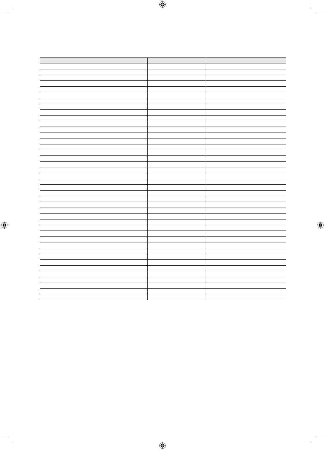
ySettings Cloned in the Hotel Menu
Menu Item Cloning Support Applicable Region
Hospitality Mode Yes All
SI Vendor Yes All except Brazil
Power On Channel EN Yes All
Power On Channel Yes All
Channel Type Yes All
Power On Volume EN Yes All
Power On Volume Yes All
Min Volume Yes All
Max Volume Yes All
Power On Source Yes All
Power On Option Yes All
Channel Setup N/A All except Hospital
Channel Editor N/A All
Channel Bank Editor N/A Smooovie SI and Hospital
Channel Bank Service Level Yes Hospital Models Only
Mixed Channel Map Yes EU
Dynamic SI Yes US and US Hsopital
Channel Rescan Message Yes EU and EU Hospital
Pan Euro MHEG Yes EU and EU Hospital
Channel Auto Store N/A Hospital Models Only
Mychannel En Yes EU and EU Hospital
Genre Editor N/A EU and EU Hospital
Picture Menu Lock Yes All
Menu Display Yes All
Channel Menu Display Yes ASIA Models only
Panel Button Lock Yes All
Mute On CC Yes US Hsopital Only
Subtitle Auto On Yes EU and EU Hospital
SW Clock Yes EU and EU Hospital
Local Time Yes EU and EU Hospital
Time Format Yes EU and EU Hospital
CLOCK Normal Dim. Yes EU
CLOCK Standby Dim. Yes EU
Music Mode AV Yes All
Music Mode PC Yes All
Music Mode Comp Yes All
Music Mode Backlight Yes All
7610 Priority AV Yes All
7610 Priority PC Yes All
7610 Priority HDMI Yes All
7610 AV Option Yes All
[HC670_677_678-ZA]Install Guide-X0ENG.indd 26 2014-01-17 8:47:52
27
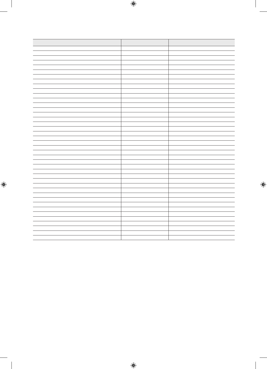
English
Menu Item Cloning Support Applicable Region
RJP HDMI Option Yes All
HDMI Music Mode Yes US and US Hsopital
Sound Bar Out Yes All
Video Out Yes ASIA Models only
USB Media Mode Yes US and EU
External Source Banner Yes All
Auto Source Yes All
Anynet+ Return Source Yes All Models except Hospital
Sub Amp Mode Yes All except US
Sub Amp Volume Yes All except US
Pillow Speaker Type Yes Hospital Models Only
Speaker Select Yes Hospital Models Only
Pillow Volume Yes Hospital Models Only
Energy Saving Yes All
Energy Saving Timer Yes EU
Welcome Message Yes All
Edit Welcome Message N/A All
Hospitality Logo Yes All
Hospitality Logo DL N/A All
Logo Display Time Yes All
Clone TV to USB N/A All
Clone USB to TV N/A All
Setting Auto Initialize Yes All
SIRCH Update Time Yes All except Brazil/ASIA_READY
SIRCH Update Immediate Yes All except Brazil/ASIA_READY
Manual SIRCH N/A All except Brazil/ASIA_READY
SIRCH Channel Yes All except Brazil/ASIA_READY
SIRCH Version N/A All except Brazil/ASIA_READY
SIRCH Group ID No US
REACH Yes All except Brazil/ASIA_READY
IPG Room Type No Guestek
CAS Yes US and US Hsopital
PI AES Data N/A US and US Hsopital
Self Diagnosis N/A All
PI AES Log Yes US and US Hsopital
View PI AES Log N/A US and US Hsopital
SW Upgrade N/A All
Service Pattern Yes All
ATV Cable AGC Gain Yes US and US Hsopital
DTV OpenCable AGC Gain Yes US and US Hsopital
TV Reset N/A All
[HC670_677_678-ZA]Install Guide-X0ENG.indd 27 2014-01-17 8:47:52
28
English
¦Multi Code Remocon
A Multi Code Remocon is a special remote which is designed to control multiple TVs.
This function is useful where there is more than one TV in a location.
You can control up to 10 TVs with a different ID code of each remote with no conflicts between the TVs. ID numbers are
displayed on each TV's OSD.
The Initial ID code for each TV is “0”.
– You can set and reset the ID code in Analog TV mode or PC mode. (Not available in DTV mode.)
– You can set the ID code to any digit from 0 to 9.
– To set a TV's ID code, follow these steps:
1. Aim the remote at the TV, and then press the MUTE button and the RETURN button simultaneously for more than
7 seconds. When you stop pressing the buttons, the TV displays the current ID in the middle of the screen and the
words, "Remote control code is set to x. If you want to change the Remote control code, enter the digit you want to
change."
2. Press the number on the remote you want to assign to the TV. The TV displays the following words:
"Remote control code is changed to x."
✎
The TV will display the OSD until you press the Exit button.
See the example below.
Remote control code is set to 0. If you want to change
Remote control code, enter the digit you want to
change.
Example: After you see the message above, if you press 1, the TV and Remote will be set to ID code 1. The TV then
displays the following message: “Remote control code is changed to 1”The TV can then only be controlled by a remote
which has the same ID code (1).
The TV can then only be controlled by a remote which has the same ID code (1).
– To reset the ID code, press the MUTE button and the EXIT button simultaneously for more than 7 seconds. When
you stop pressing the buttons, the ID codes of the TV and Remote are reset to “0”. “Remote control code is set to 0.”
appears on the TV.
[HC670_677_678-ZA]Install Guide-X0ENG.indd 28 2014-01-17 8:47:53
29
English
¦Setting Auto Initialize
When you clone settings from one TV to another, you clone both the guest side menu and hotel side menu settings: Picture,
Sound, Input, Channel, Setup, and Hotel Setup. This lets you set nearly all of the menu values on your hospitality TVs to
the same, standard settings. If you allow guests access to the guest side menus, for example the Picture menu, they can
change the settings in those menus so they are no longer standard. If you set the Setting Auto Initialize function to on the TV
automatically restores (initializes) any guest-side menu values to the cloned, standard values when the TV is turned off and then
turned on again. Note that Setting Auto Initialize works on cloned guest side menu values only. Settings which have not been
cloned are ignored.
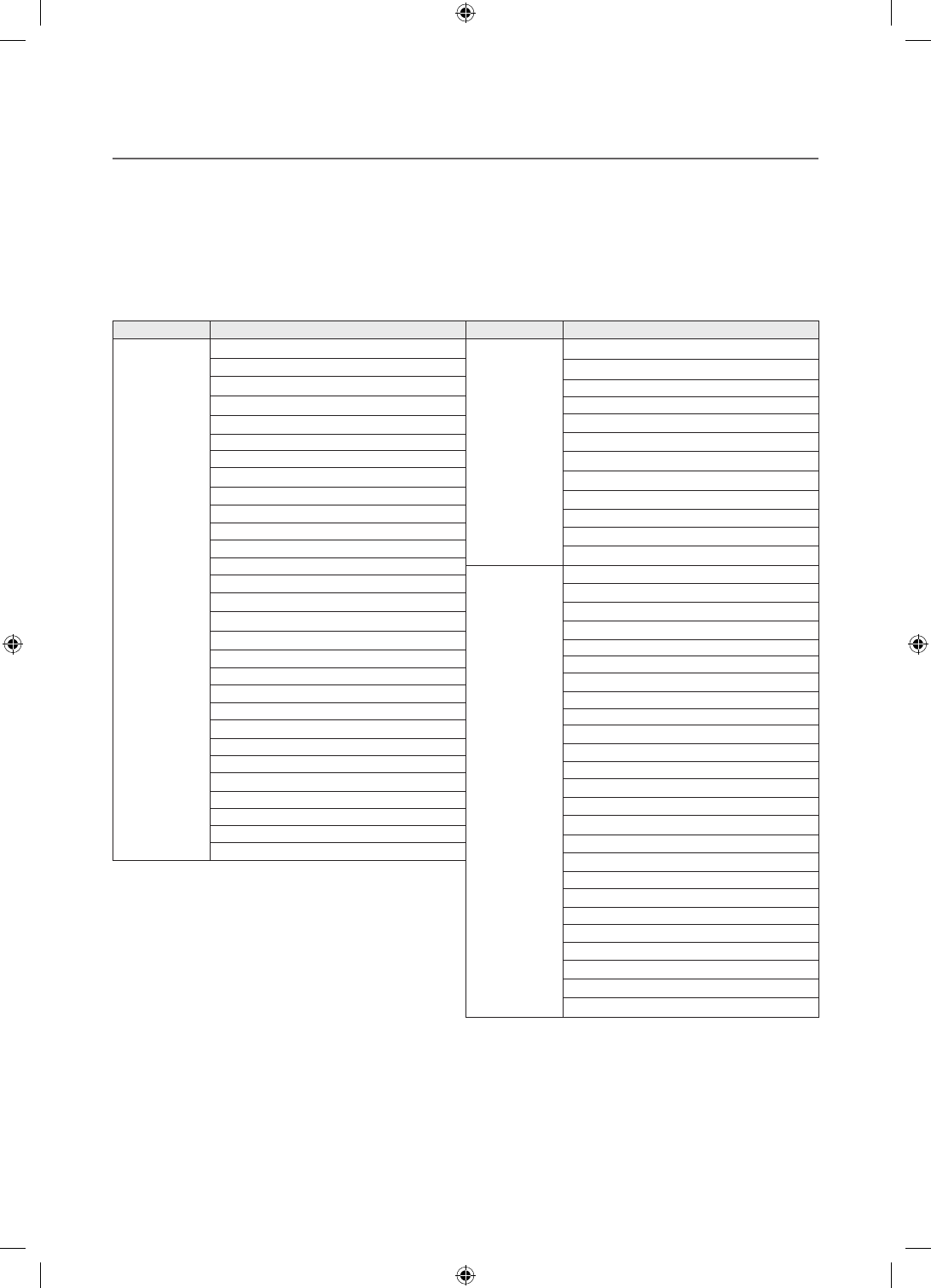
The table below lists the settings that are restored to their cloned values when you set the Setting Auto Initialize function to on.
Menu Menu Item
Picture Menu
Picture Mode
Backlight
Contrast
Brightness
Sharpness
Color
Tint (G/R)
Picture Size
Picture Size
Position
PIP
Advanced Settings
Dynamic Contrast
Black Tone
Flesh Tone
RGB Only Mode
Color Space
White Balance
Gamma
Motion Lighting
Picture Option
Color Tone
Digital Clean View
MPEG Noise Filter
HDMI Black Level
Film Mode
LED Clear Motion
Picture Off
Reset Picture
Menu Menu Item
Sound Menu
Sound Mode
Sound Effect
DTS TruSurround
DTS TruDialog
Equalizer
Speaker Settings
Speaker Select
Auto Volume
Digital Audio Out
Audio Format
Audio Delay
Reset Sound
System Menu
Menu Language
Time
Clock
Sleep Timer
Wake-up Timer
Device Manager
Keyboard Settings
Mouse Settings
Eco Solution
Energy Saving
Eco Sensor
No Signal Power Off
Auto Power Off
Auto Protection Time
Change PIN
General
Game Mode
BD Wise
Menu Transparency
Sound Feedback
Boot Logo
Anynet+ (HDMI-CEC)
Anynet+ (HDMI-CEC)
Auto Turn Off
Divx® Video On Demand
[HC670_677_678-ZA]Install Guide-X0ENG.indd 29 2014-01-17 8:47:53
30
English
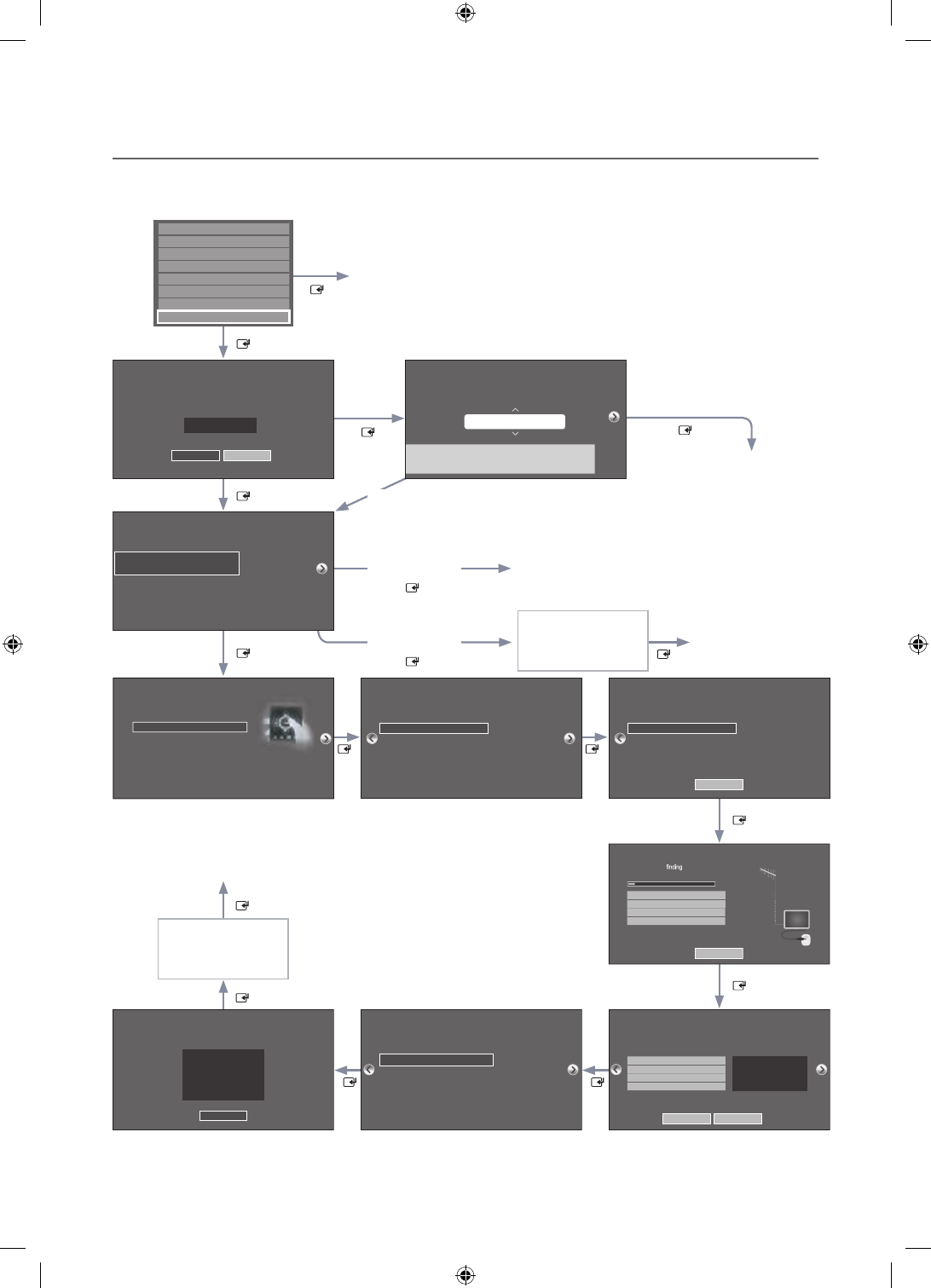
¦Hotel Plug & Play
The Hotel Plug & Play function, which automatically performs the Hotel mode selection, Country Setup, Clock Setup, and
Picture mode Setup, runs once when power is first turned ON. Setup also runs automatically after you have executed a
Service Reset. (HC678 model none)
Self Diagnosis for TV
Self Diagnosis for HTV
SW Update
Service Pattern
ATV Cable AGC Gain
OFF
DTV OpenCable AGC Gain
Sound Bar OutOFF
Default
Default
TV Reset
If you select
Change
If you select
Standalone Only
If you select
Interactive
TV will enter the RF mode.
Press Power OFF to exit.
Interactive
Hospitality Option Menu
appears.
If you don't change the country of the Current Location
If you select Skip
If you select
Standalone
Plug&Play
Select your language
Press Power OFF to exit.
Select Picture mode
Select Clock Mode, DST, and your Time Zone
Select the channel
band to use for Auto
Program
After Searching
channels.
If you select Factory Reset, the TV resets all values to their factory
defaults and then displays the Hotel Plug & Play menu. Go to the
first Hotel Plug & Play screen below.
The TV is automatically
turned off and on.
If you change the country
of the Current Location
Local Set
Change Locat Set if Located in North America, Latin America and Europe.
In other regions, Please press SKIP button move to the next step.
Current Localset : US
Change Skip
Local Set
Change Locat Set if Located in North America, Latin America and Europe.
In other regions, Please press SKIP button move to the next step.
Current Localset : US
Change Skip
Easy Set up
Intertactive
(Hotel Menu)
Standalone Setup
(Continue Setup)
Standalone Only
(End Setup)
If you select this, the
setup process will be
completed and go to
hotel menu
c
Select your Language
Select your language to start the on screen setup.
The Language Setting will be applied to Main Menu and not Plug and Play.
Press the ▲▼◄►
buttons to move the
highlight.
Press the enter button
to select.
English
Español
Français
age
Press
the
▲▼◄►
c
Configure your TV
Picture Mode Standard
Choose a picture mode
that best suits your
viewing enviroment.
Select your information in all of the categories
below.
TV Setup Complete!
Your TV is now ready to use
OK
Auto Program
Antenna Both
Digital Cable System STD
Analog Cable System STD
Select current connected
antenna.
To get channels, set the options below then select
Scan.
Scan
Auto Program
Auto Program is channels for you...
Air 21 6%
Stop
DTV Air0
Air
DTV Cable
Cable
0
0
0
Clock
-- : -- --
You can adjust your time to set DST, Time Zone and
clock mode. Set current date and time
Clock Mode Auto
Date -- / -- / ----
Time -- : -- --
DST Off
Time Zone Eastern
Auto Program
Auto Program is incomplete.
0 channels are memorized.
Change Settings Scan Again
DTV Air0
Air
DTV Cable
Cable
0
0
0
Local Set
Warning! TV might not function if Local Set is not correctly configured.
When Local set is changed, TV will turn off automatically to apply it.
US
Countries List
USA
Standalone
Hospitality Option Menu
appears.
[HC670_677_678-ZA]Install Guide-X0ENG.indd 30 2014-01-17 8:47:54

31
English
yHotel Plug & Play OSD
– Initially highlighted: Interactive
– If you select the Standalone Only button, the Standalone hotel mode is set by default and the “Standalone mode is set”
OSD appears for 3 seconds.
TV enters RF mode automatically after displaying the “Standalone mode is set” OSD for 3 seconds.
– If you select the Interactive mode, the Interactive Setup Menu is displayed. Press the power off key to exit from the
Interactive menu.
– If you select the Standalone Plug & Play mode, the “Select Menu Language” OSD appears.
yLocalSet
– Initially highlighted: US
– If you press the Enter key after selecting Change, you can change the country.
– If the country is changed, the TV automatically turns off and on.
– If you select the Interactive mode, the Interactive Setup Menu is displayed. Press the power off key to exit from the
Interactive menu.
– If you select the incorrect country, execute TV Reset again after entering the Service section of the Hotel Menu.
ySelect Menu Language OSD
– If you select Standalone from the “Select Hotel TV Mode” OSD, the “Select Menu Language” OSD appears.
– Initially highlighted: English
– Display time: OSD time out and operation are the same as Samsung's consumer TV models.
– If you press the Enter key, the “Picture Mode” OSD appears
yPicture Mode OSD
– Initially highlighted: Standard.
– The TV displays the Picture Mode OSD where you can choose the Dynamic or a Standard Picture mode.
yAuto Search Mode OSD
– If you press the Enter key, the TV automatically searches for channels.
– The OSD Display time, which starts when the Auto Store operation is completed and continues until the Auto Sort
function starts, is 30 seconds.
ySet Clock Mode, DST(Daylight saving time), and Time Zone OSD
– Initially highlighted:
Clock Mode : Auto, DST : Off, Time Zone : Eastern
– If the TV will be tuned to digital broadcast channels, and these channels transmit date and time information, set the
Clock Mode to Auto. The TV will set the date and time automatically.
– If the TV will not be tuned to digital broadcast channels, set the Clock Mode to Manual, and then set the date and time
on the TV manually.
– Set DST On or Off to apply or not apply daylight saving time to the TV.
– Select your time zone on the map that appears.
[HC670_677_678-ZA]Install Guide-X0ENG.indd 31 2014-01-17 8:47:54
32
English
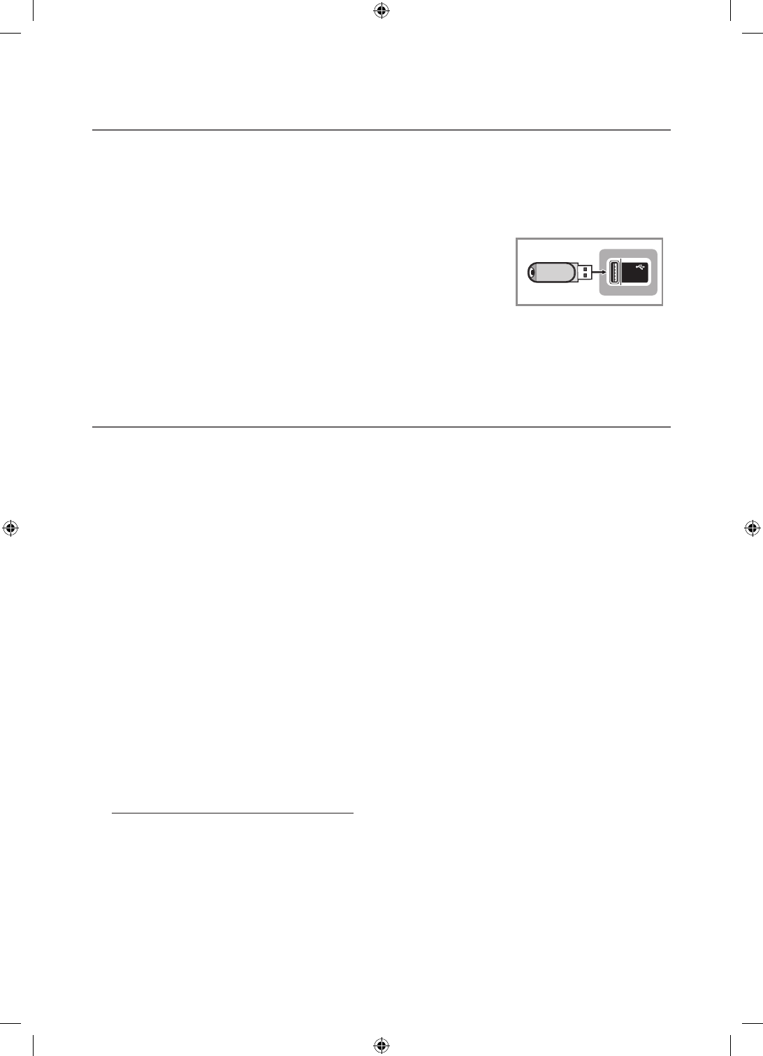
¦USB Software Upgrade Method
Samsung may offer upgrades to the TV’s SW in the future. Please contact the Samsung Hospitality Hot line at 1-866-894-
0524 to receive information about downloading upgrades and using a USB drive to update the SW by connecting the USB
drive containing the upgrade to the USB port located on the TV.
When the software is upgraded, video and audio settings you have made will return to their default (factory) settings. We
recommend you clone the hotel settings so that you can easily reset them after the upgrade.
To upgrade the TV's software, follow these steps:
1. Insert a USB drive containing the SW upgrade into the USB port on the side of the TV.
2. Press the MENU button to display the menu.
Press the ▲ or ▼ button to select Support, and then press the ENTER
E
button.
3. Press the ▲ or ▼ button to select SW Upgrade, and then press the ENTER
E
button.
The message "Scanning for USB. This may take more than 1min." is displayed.
4. The message "Upgrade version XXXX to version XXXX? The system will be reset
after upgrade." is displayed.
Press the ◄ or ► to select the OK, and then press the ENTER
E
button.
(5V 0.5A)
/ CLONING
USB
Please be careful to not disconnect the power or remove the USB drive while upgrades are being applied. The TV will turn off
and turn on automatically after completing the SW upgrade. Please check the SW version after the upgrades are complete.
¦Sound Bar
ySamsung Sound-Bars and Hospitality TVs in 2013
– Samsung Sound-Bars and hospitality TVs support the ARC feature in HDMI 1.4. If you connect a compatible Samsung
Sound-Bar to a compatible Samsung hospitality TV using a single HDMI cable, guests can listen to the TV's sound
through the Sound-Bar.
– The item of Sound bar Out in Hospitality Option Menu makes you control to where the TV sound is outputted when the
TV is turned on.
If Sound bar Out is On, the TV sound is automatically outputted in the Sound Bar device only whenever TV is turned on.
If Sound bar Out is Off, the TV sound is automatically outputted in the TV speaker only whenever TV is turned on.
– Models supporting the ARC function are listed below:
ySound-Bars: HW-E350/E450/E550
HW-F350/F355/FM35/F450/FM45/FM45C/F550/F551/FM55/FM55C/F750/F751
ySetting the Sound-Bars to Hotel Mode.
1. Set the following Hotel menu options:
– Hotel option > External Device > Sound Bar Out = On.
– Hotel option > Power On > Power On Volume EN = User Defined.
– Hotel option > Power On > Power On Volume > Set greater than 0.
– Hotel option > Power On > Max Volume > Set greater than 0.
2. Connect an HDMI cable from the HDMI OUT jack on the back of the Sound-Bar to the HDMI3 port (supporting ARC)
on the hospitality TV.
3. After the Sound-Bar is connected to the hospitality TV, when the TV turns on, the Sound-Bar automatically detects the
TV, and then automatically switches to Hotel Mode.
Sound Bar Hotel mode functional characteristics:
yPower On/Off is synchronized with the TV
yHDMI_CEC defaults set to On
yFunctions through the “HDMI OUT” port only
yDisables the "Input mode" key on the VFD to prevent unexpected audio-source changes.
yAcquires adjustable Power On and Max Volume settings from the TV’s Hotel option menu. The Sound-Bar's Power
On Volume and Max Volume values, however, are ½ of the Power On Volume and Max Volume settings in the TV's
Hotel option menu. Example: If the TV's Power On Volume=20 and Max Volume=90, then the Sound Bar's Power
On Volume=10 and Max Volume=45.
[HC670_677_678-ZA]Install Guide-X0ENG.indd 32 2014-01-17 8:47:54