Samsung Electronics Co L7IU-B1C Indoor Pico User Manual Model Name Manual Name
Samsung Electronics Co Ltd Indoor Pico Model Name Manual Name
UserManual.wiki
>
Samsung Electronics Co
>
L7IU B1C User Manual
User Manual
Navigation menu
Upload a User Manual
Namespaces
Wiki Guide
HTML
PDF
Info
Views
User Manual
Discussion / Help
Navigation
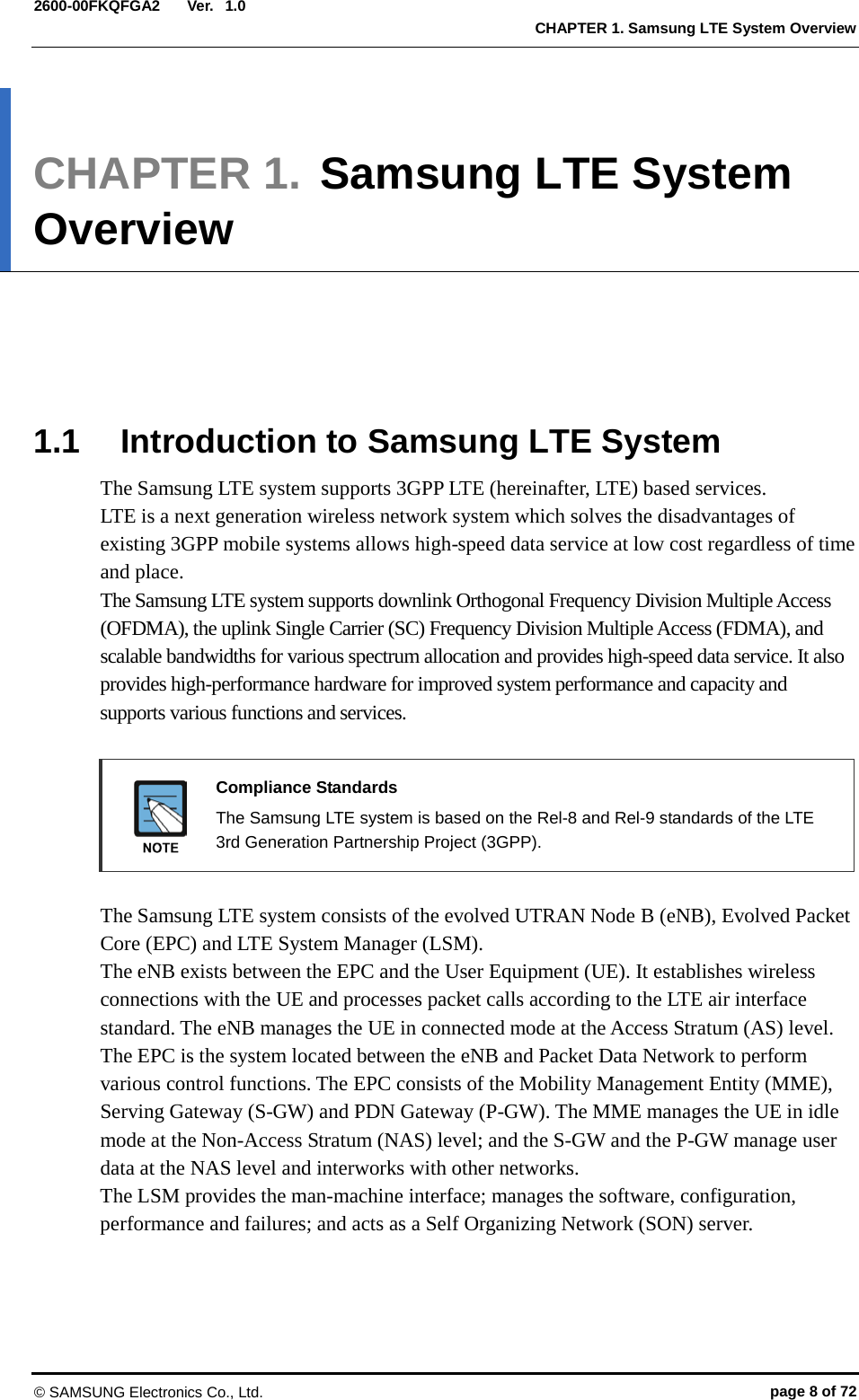
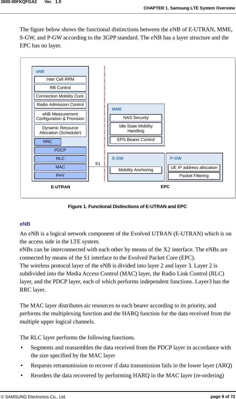
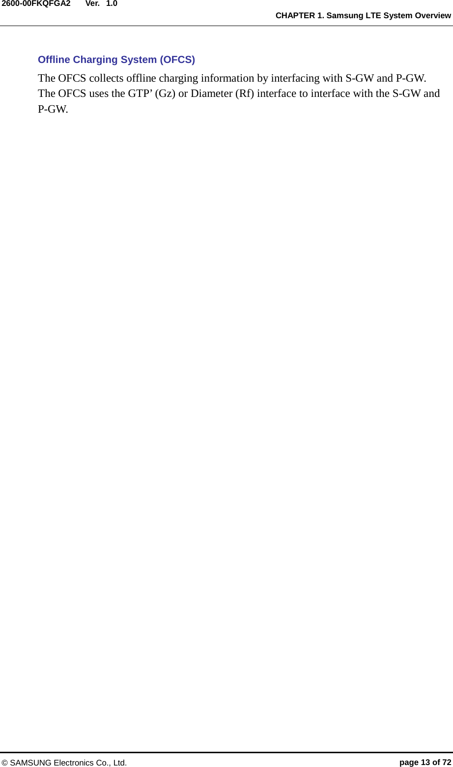
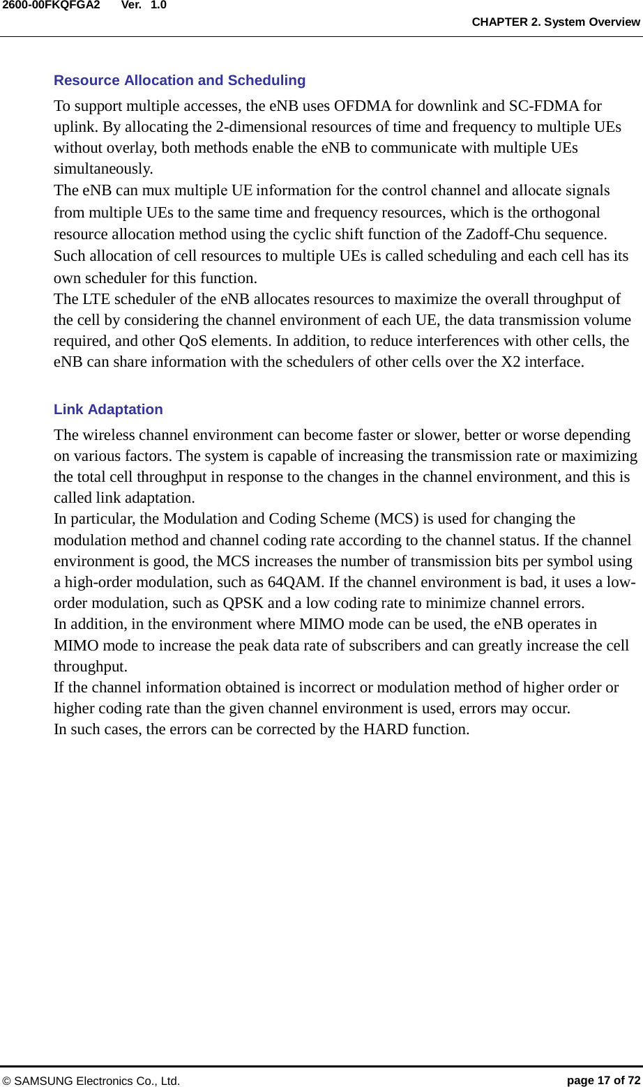
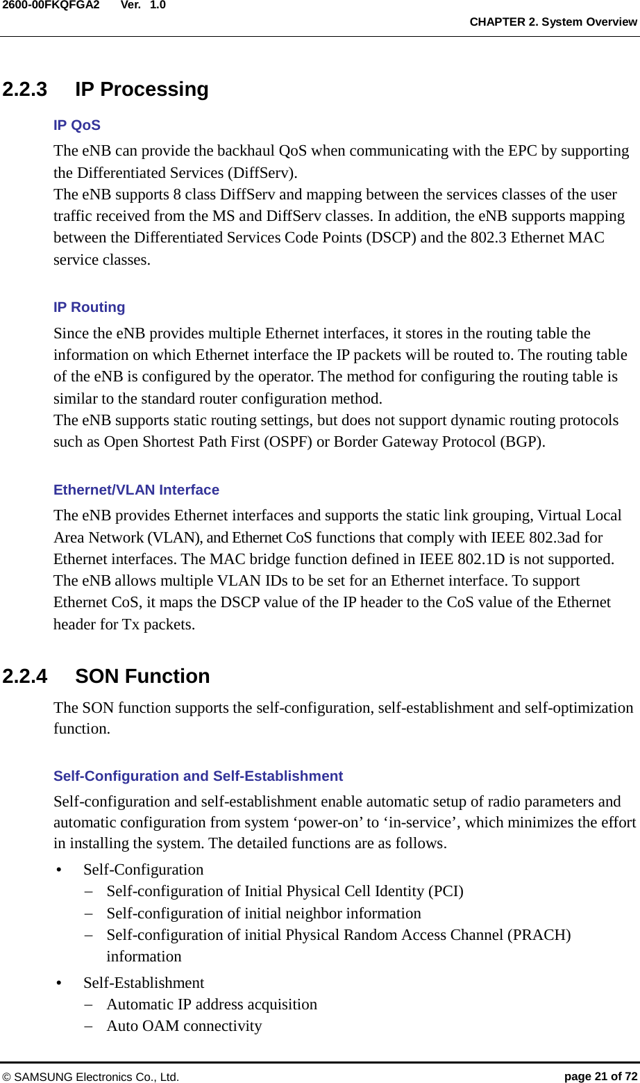
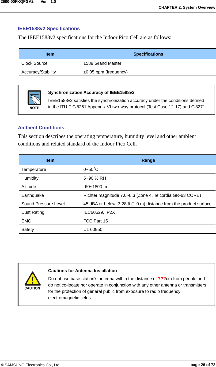
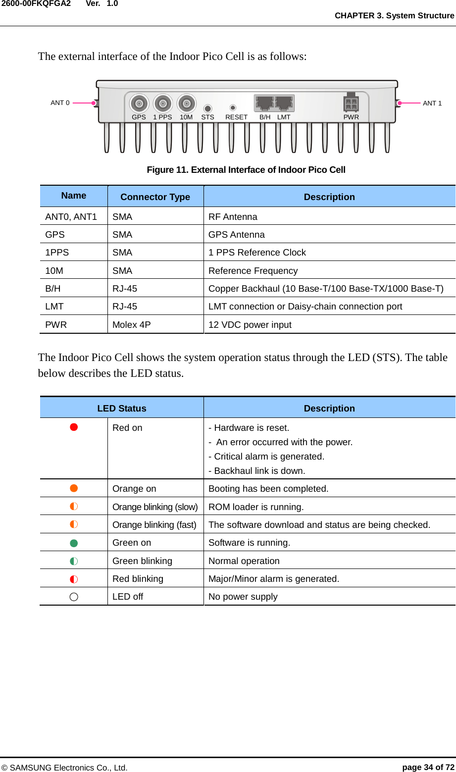
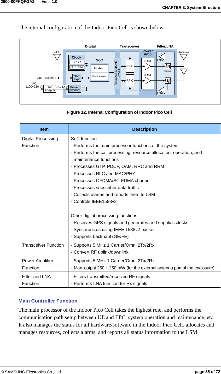
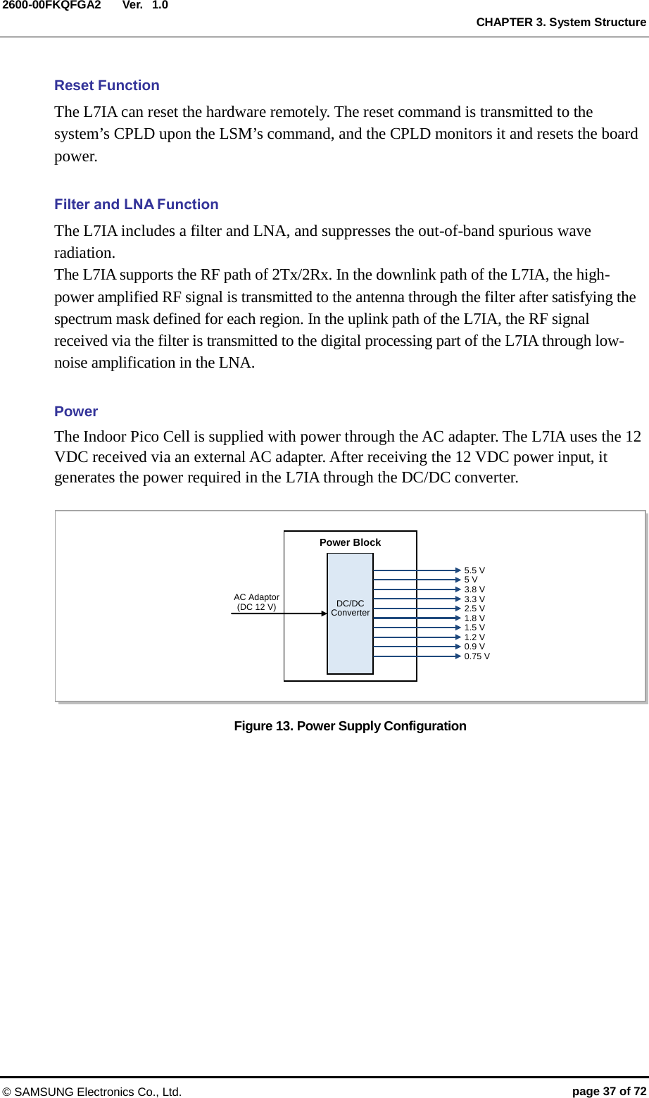
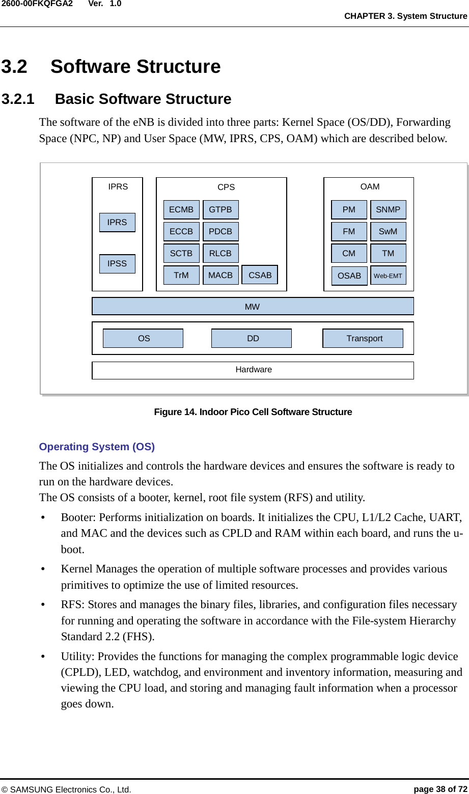
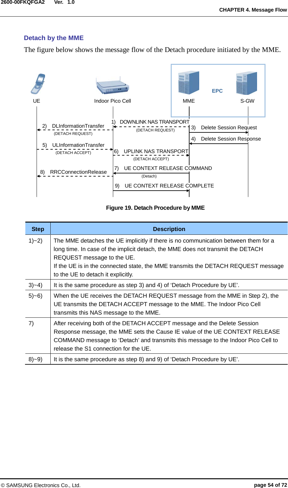
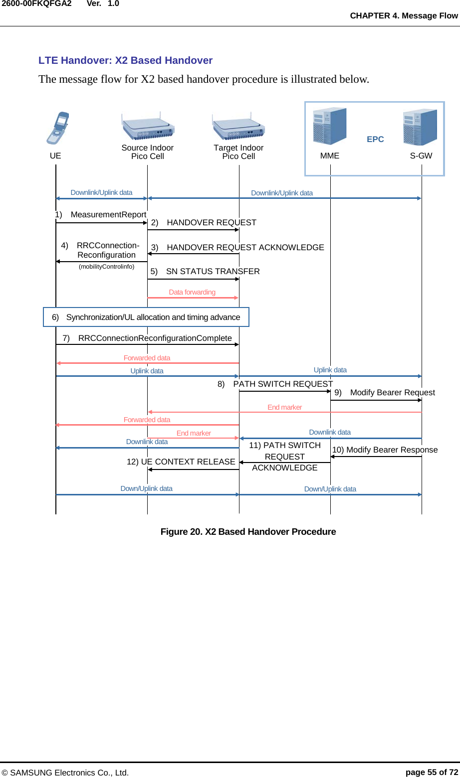
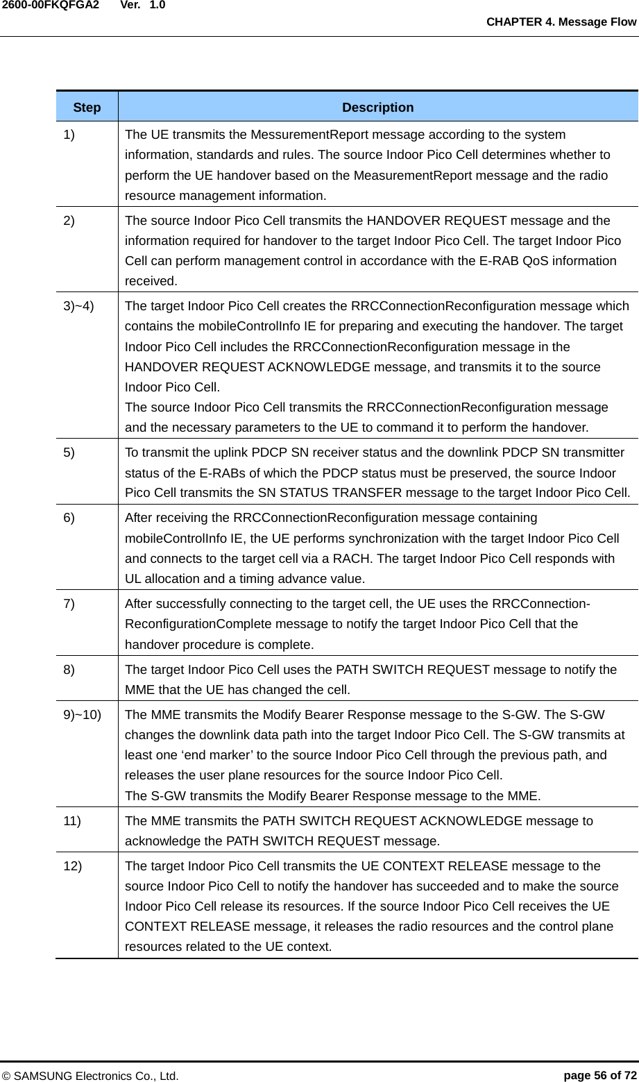
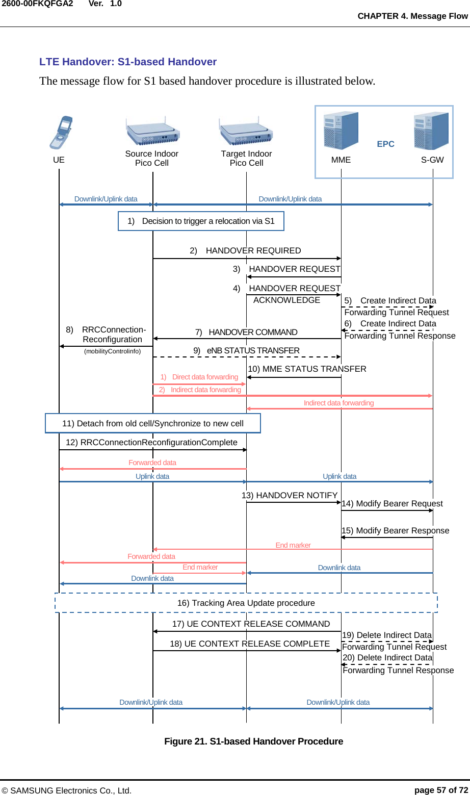
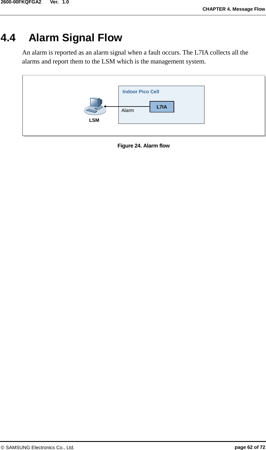
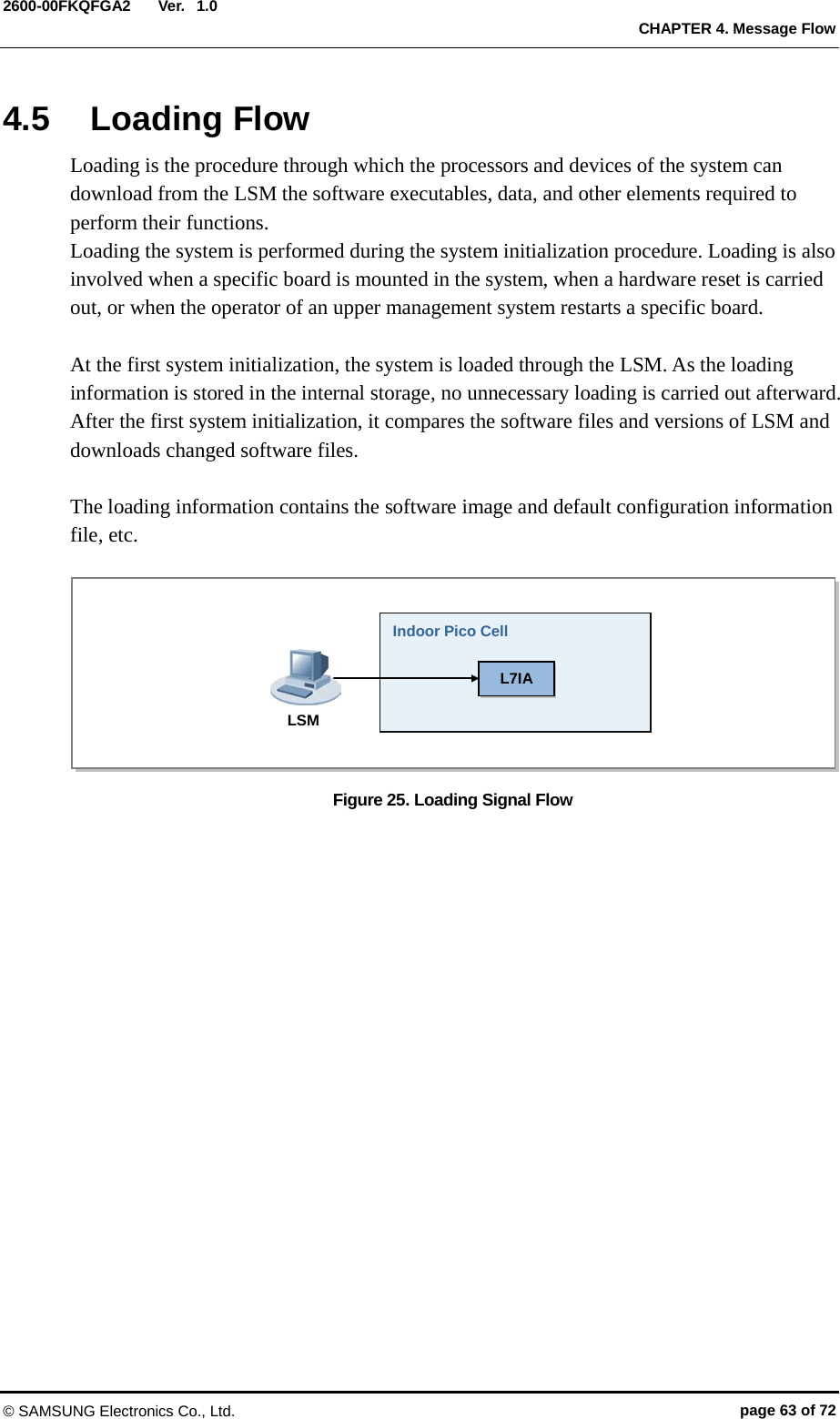
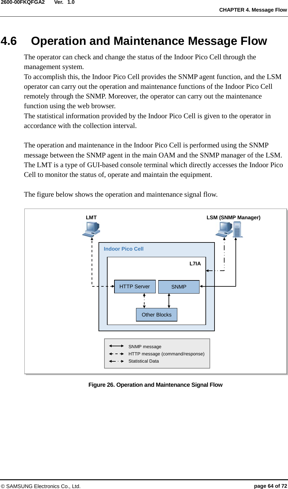
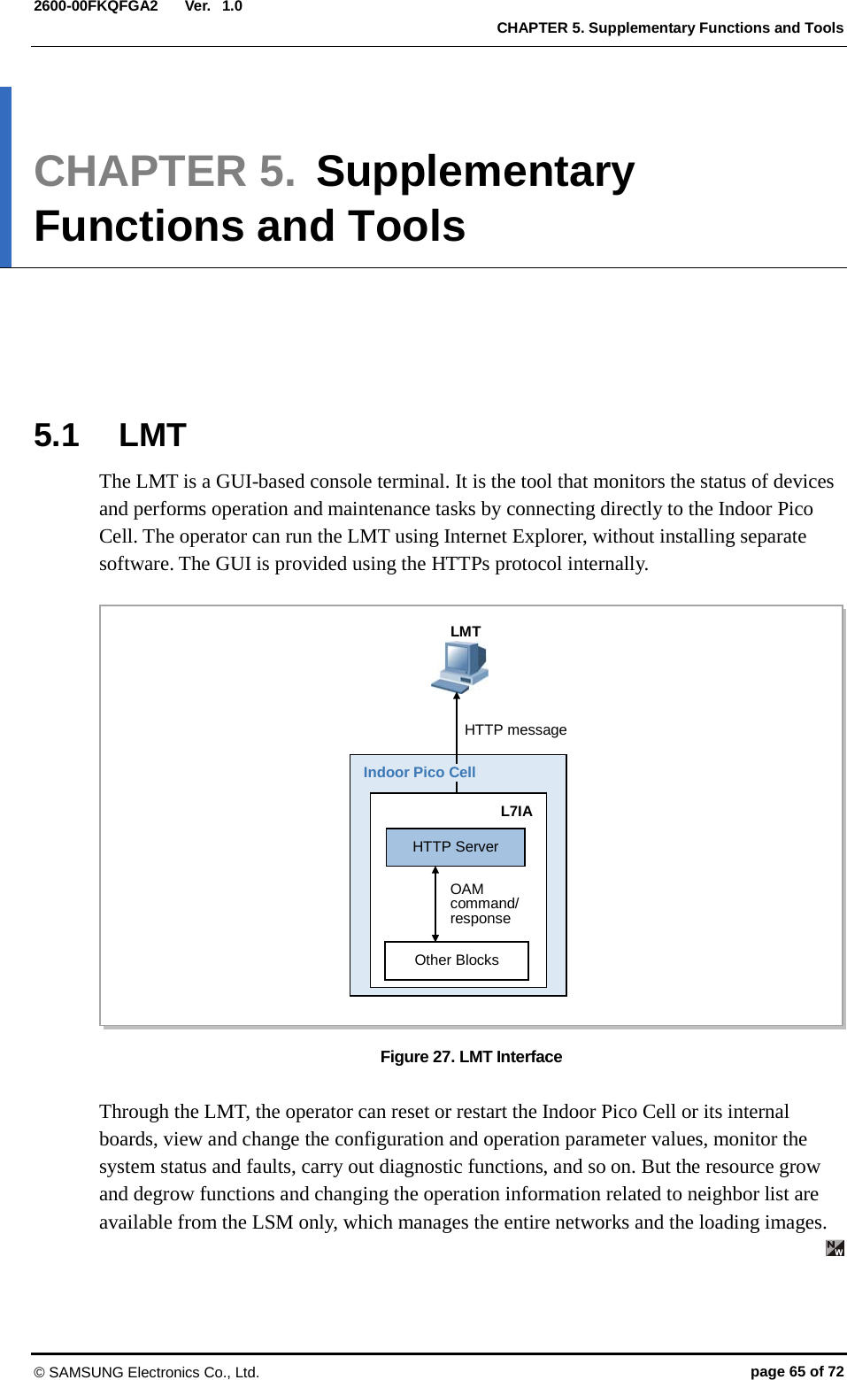
![Ver. CHAPTER 2. System Overview 2600-00FKQFGA2 1.0 2.3 Specifications Key Specifications The key specifications of the Indoor Pico Cell are as follows: Item Specifications Radio Specifications FDD LTE Operating Frequency 1.9 GHz Channel Bandwidth 5 MHz Peak Throughput (Mbps) (with Category 3 UE) DL: 31.7 Mbps (2x2 MIMO), UL: 10.1 Mbps (1x2 SIMO) (Calculation conditions: DL 1 % PHY error, UL 1 % PHY error) Tx Power 250 mW/Path (Total 500 mW) Antenna Configuration 2Tx/2Rx Backhaul Gigabit Ethernet 1 port (Copper) Holdover N/A Input Power The power specifications of the Indoor Pico Cell are as follows: Item Specifications Indoor Pico Cell External AC adapter (100~254 VAC) Dimensions and Weight The dimensions and weight of the Indoor Pico Cell are as follows: Item Specifications Size (W×D×H) [in. (mm)] 9.06 (230) × 2.36 (60) × 10.63 (270) Weight [lb (kg)] 7.72 (3.5) or less GPSR Specifications The specifications of the Indoor Pico Cell’s GPS receiver (GPSR) are as follows: Item Specifications Received Signal from GPS GPS L1 Signal Accuracy/Stability ±0.05 ppm (frequency) © SAMSUNG Electronics Co., Ltd. page 25 of 72](https://usermanual.wiki/Samsung-Electronics-Co/L7IU-B1C/User-Guide-2015930-Page-25.png)