Samsung Electronics Co L7IU-B1C Indoor Pico User Manual Model Name Manual Name
Samsung Electronics Co Ltd Indoor Pico Model Name Manual Name
User Manual
Ver.
2600-00FKQFGA2
1.0
LTE 1.9 GHz Indoor Pico Cell
System Description

Ver.
2600-00FKQFGA2
1.0
COPYRIGHT
This manual is proprietary to SAMSUNG Electronics Co., Ltd. and is protected by copyright.
No information contained herein may be copied, translated, transcribed or duplicated for any commercial
purposes or disclosed to the third party in any form without the prior written consent of SAMSUNG Electronics
Co., Ltd.
TRADEMARKS
Product names mentioned in this manual may be trademarks and/or registered trademarks of their respective
companies.
This manual should be read and used as a guideline for properly installing and operating the product.
All reasonable care has been made to ensure that this document is accurate. If you have any comments on
this manual, please contact our documentation centre at the following address:
Address: Document Center 3rd Floor Jeong-bo-tong-sin-dong. 129, Samsung-ro, Yeongtong-gu, Suwon-si,
Gyeonggi-do, Korea 443-742
Homepage: http://www.samsungdocs.com
©2013 SAMSUNG Electronics Co., Ltd. All rights reserved.

Ver.
INTRODUCTION
2600-00FKQFGA2
1.0
INTRODUCTION
Purpose
This description describes the characteristics, features and structure of the 1.9 GHz Indoor
Pico Cell, an LTE eNB.
Document Content and Organization
This manual consists of five Chapters and a list of Abbreviations.
CHAPTER 1. Samsung LTE System Overview
Introduction to Samsung LTE System
Samsung LTE Network Configuration
CHAPTER 2. System Overview
Introduction to System
Main Functions
Specifications
Intersystem Interface
CHAPTER 3. System Structure
Hardware Structure
Software Structure
CHAPTER 4. Message Flow
Call Processing Message Flow
Data Traffic Flow
Network Sync Flow
Alarm Signal Flow
Loading Flow
Operation and Maintenance Message Flow
© SAMSUNG Electronics Co., Ltd. page 3 of 72

Ver.
INTRODUCTION
2600-00FKQFGA2
1.0
CHAPTER 5. Supplementary Functions and Tools
LMT
ABBREVIATION
Describes the acronyms used in this manual.
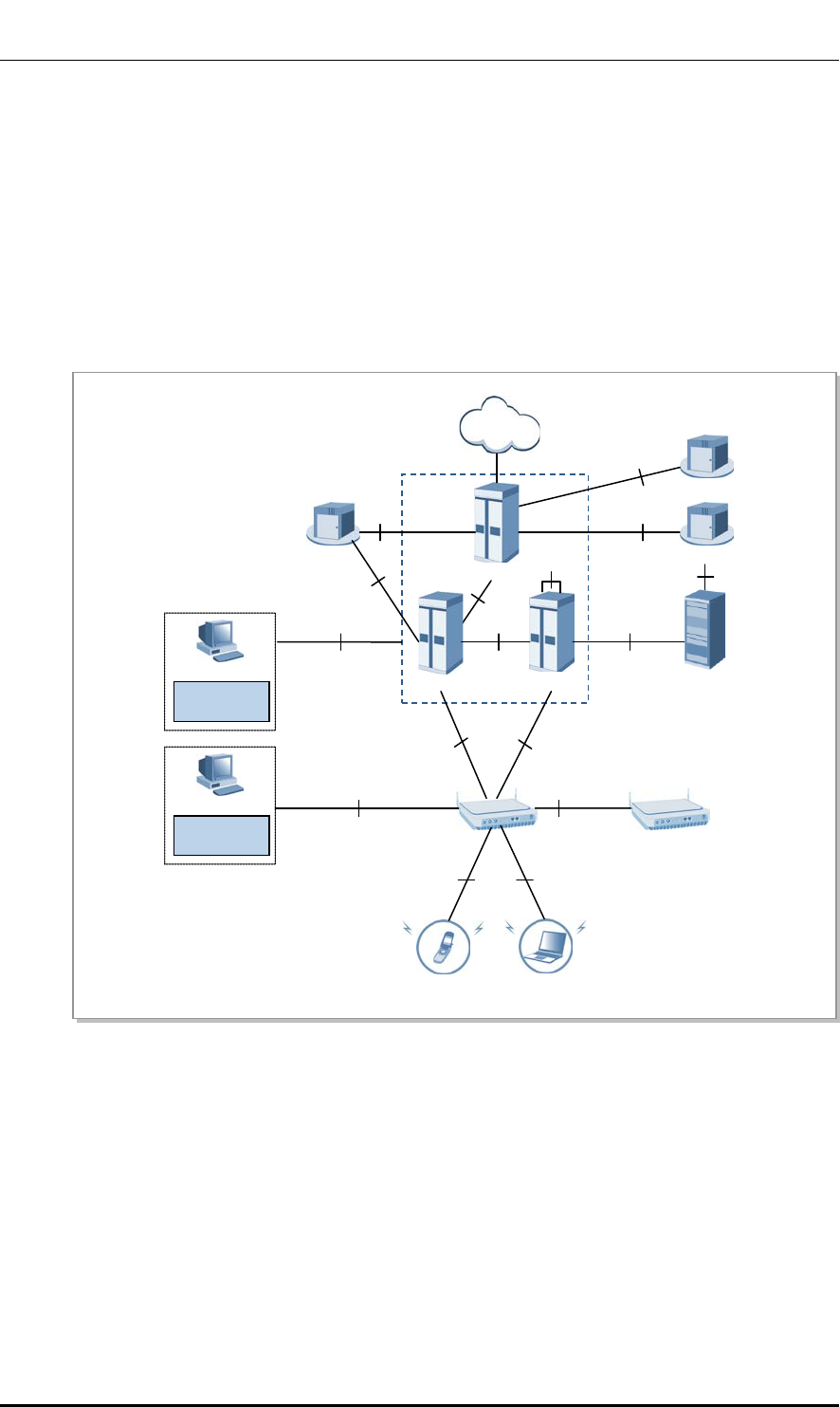
Conventions
The following types of paragraphs contain special information that must be carefully read
and thoroughly understood. Such information may or may not be enclosed in a rectangular
box, separating it from the main text, but is always preceded by an icon and/or a bold title.
NOTE
Indicates additional information as a reference.
Revision History
VERSION DATE OF ISSUE REMARKS
1.0
04. 2013.
First Version
© SAMSUNG Electronics Co., Ltd. page 4 of 72

Ver.
TABLE OF CONTENTS
2600-00FKQFGA2
1.0
TABLE OF CONTENTS
INTRODUCTION 3
Purpose ..................................................................................................................................................... 3
Document Content and Organization ...................................................................................................... 3
Conventions ............................................................................................................................................... 4
Revision History ........................................................................................................................................ 4
CHAPTER 1. Samsung LTE System Overview 8
1.1 Introduction to Samsung LTE System .................................................................................... 8
1.2 Samsung LTE Network Configuration .................................................................................... 11
CHAPTER 2. System Overview 14
2.1 ntroduction to System .............................................................................................................14
2.2 Main Functions ........................................................................................................................15
2.2.1 Physical Layer Processing ......................................................................................................... 15
2.2.2 Call Processing Function ........................................................................................................... 19
2.2.3 IP Processing .............................................................................................................................. 21
2.2.4 SON Function ............................................................................................................................. 21
2.2.5 Easy Operation and Maintenance ............................................................................................. 23
2.3 Specifications...........................................................................................................................25
2.4 Intersystem Interface ...............................................................................................................28
2.4.1 Interface Structure ...................................................................................................................... 28
2.4.2 Protocol Stack ............................................................................................................................. 29
CHAPTER 3. System Structure 33
3.1 Hardware Structure ..................................................................................................................33
3.2 Software Structure ...................................................................................................................38
3.2.1 Basic Software Structure ............................................................................................................ 38
3.2.2 CPS Block ................................................................................................................................... 40
3.2.3 OAM Blocks ................................................................................................................................ 43
© SAMSUNG Electronics Co., Ltd. page 5 of 72

Ver.
TABLE OF CONTENTS
2600-00FKQFGA2
1.0
CHAPTER 4. Message Flow 46
4.1 Call Processing Message Flow .............................................................................................. 46
4.2 Data Traffic Flow ...................................................................................................................... 60
4.3 Network Sync Flow.................................................................................................................. 61
4.4 Alarm Signal Flow ................................................................................................................... 62
4.5 Loading Flow ........................................................................................................................... 63
4.6 Operation and Maintenance Message Flow .......................................................................... 64
CHAPTER 5. Supplementary Functions and Tools 65
5.1 LMT ........................................................................................................................................... 65
ABBREVIATION 66
LIST OF FIGURES
Figure 1. Functional Distinctions of E-UTRAN and EPC .............................................................. 9
Figure 2. Samsung LTE System Architecture ............................................................................. 11
Figure 3. Inter-System Interface Structure .................................................................................. 28
Figure 4. Protocol Stack between UE and eNB .......................................................................... 29
Figure 5. Protocol Stack between eNB and S-GW User Plane ................................................... 30
Figure 6. Protocol Stack between eNB and MME Control Plane ................................................ 30
Figure 7. Inter-eNB User Plane Protocol Stack ........................................................................... 31
Figure 8. Inter-eNB Control Plane Protocol Stack ....................................................................... 31
Figure 9. Interface Protocol Stack between eNB and LSM ......................................................... 32
Figure 10. Indoor Pico Cell Configuration ................................................................................... 33
Figure 11. External Interface of Indoor Pico Cell ........................................................................ 34
Figure 12. Internal Configuration of Indoor Pico Cell .................................................................. 35
Figure 13. Power Supply Configuration ...................................................................................... 37
Figure 14. Indoor Pico Cell Software Structure ........................................................................... 38
Figure 15. Attach Procedure ....................................................................................................... 47
Figure 16. Service Request Procedure by UE ............................................................................ 50
Figure 17. Service Request Procedure by Network .................................................................... 52
Figure 18. Detach Procedure by UE ........................................................................................... 53
Figure 19. Detach Procedure by MME ....................................................................................... 54
Figure 20. X2 Based Handover Procedure ................................................................................. 55
Figure 21. S1-based Handover Procedure ................................................................................. 57
© SAMSUNG Electronics Co., Ltd. page 6 of 72

Ver.
TABLE OF CONTENTS
2600-00FKQFGA2
1.0
Figure 22. Data Traffic Flow ........................................................................................................60
Figure 23. Network Synchronization Flow ...................................................................................61
Figure 24. Alarm flow ..................................................................................................................62
Figure 25. Loading Signal Flow...................................................................................................63
Figure 26. Operation and Maintenance Signal Flow ...................................................................64
Figure 27. LMT Interface .............................................................................................................65
© SAMSUNG Electronics Co., Ltd. page 7 of 72

Ver.
CHAPTER 1. Samsung LTE System Overview
2600-00FKQFGA2
1.0
CHAPTER 1. Samsung LTE System
Overview
1.1 Introduction to Samsung LTE System
The Samsung LTE system supports 3GPP LTE (hereinafter, LTE) based services.
LTE is a next generation wireless network system which solves the disadvantages of
existing 3GPP mobile systems allows high-speed data service at low cost regardless of time
and place.
The Samsung LTE system supports downlink Orthogonal Frequency Division Multiple Access
(OFDMA), the uplink Single Carrier (SC) Frequency Division Multiple Access (FDMA), and
scalable bandwidths for various spectrum allocation and provides high-speed data service. It also
provides high-performance hardware for improved system performance and capacity and
supports various functions and services.
Compliance Standards
The Samsung LTE system is based on the Rel-8 and Rel-9 standards of the LTE
3rd Generation Partnership Project (3GPP).
The Samsung LTE system consists of the evolved UTRAN Node B (eNB), Evolved Packet
Core (EPC) and LTE System Manager (LSM).
The eNB exists between the EPC and the User Equipment (UE). It establishes wireless
connections with the UE and processes packet calls according to the LTE air interface
standard. The eNB manages the UE in connected mode at the Access Stratum (AS) level.
The EPC is the system located between the eNB and Packet Data Network to perform
various control functions. The EPC consists of the Mobility Management Entity (MME),
Serving Gateway (S-GW) and PDN Gateway (P-GW). The MME manages the UE in idle
mode at the Non-Access Stratum (NAS) level; and the S-GW and the P-GW manage user
data at the NAS level and interworks with other networks.
The LSM provides the man-machine interface; manages the software, configuration,
performance and failures; and acts as a Self Organizing Network (SON) server.
© SAMSUNG Electronics Co., Ltd. page 8 of 72
Ver.
CHAPTER 1. Samsung LTE System Overview
2600-00FKQFGA2
1.0
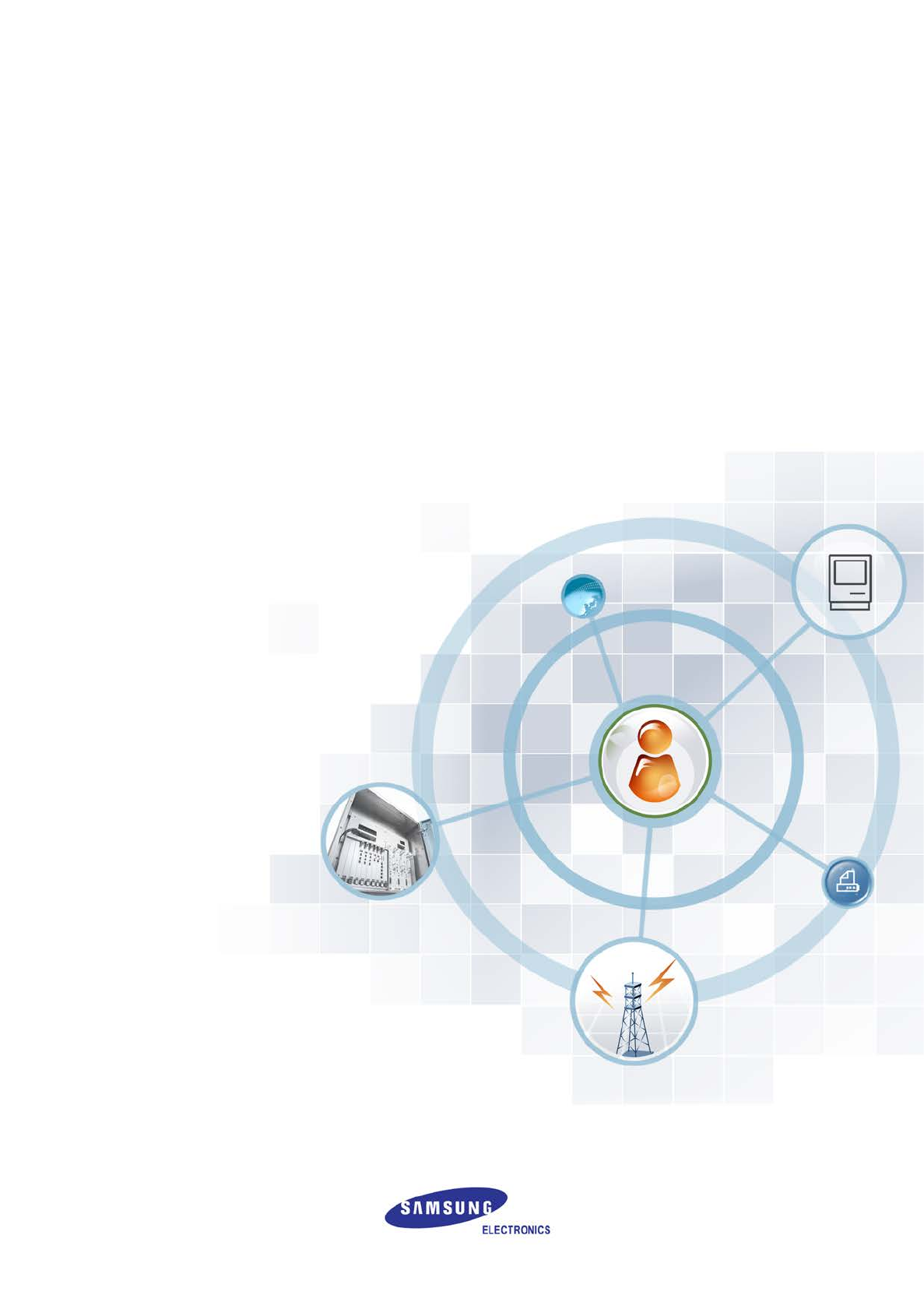
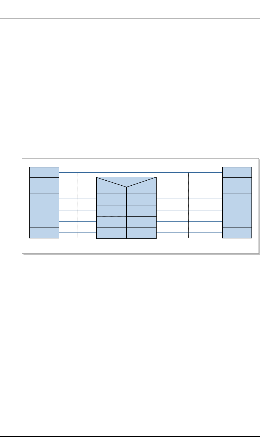
The figure below shows the functional distinctions between the eNB of E-UTRAN, MME,
S-GW, and P-GW according to the 3GPP standard. The eNB has a layer structure and the
EPC has no layer.
Figure 1. Functional Distinctions of E-UTRAN and EPC
eNB
An eNB is a logical network component of the Evolved UTRAN (E-UTRAN) which is on
the access side in the LTE system.
eNBs can be interconnected with each other by means of the X2 interface. The eNBs are
connected by means of the S1 interface to the Evolved Packet Core (EPC).
The wireless protocol layer of the eNB is divided into layer 2 and layer 3. Layer 2 is
subdivided into the Media Access Control (MAC) layer, the Radio Link Control (RLC)
layer, and the PDCP layer, each of which performs independent functions. Layer3 has the
RRC layer.
The MAC layer distributes air resources to each bearer according to its priority, and
performs the multiplexing function and the HARQ function for the data received from the
multiple upper logical channels.
The RLC layer performs the following functions.
Segments and reassembles the data received from the PDCP layer in accordance with
the size specified by the MAC layer
Requests retransmission to recover if data transmission fails in the lower layer (ARQ)
Reorders the data recovered by performing HARQ in the MAC layer (re-ordering)
S1
MME
NAS Security
Idle State Mobility
Handling
EPS Bearer Control
S-GW
Mobility Anchoring
P-GW
Packet Filtering
UE IP address allocation
EPC
eNB
Inter Cell RRM
RB Control
Connection Mobility Cont.
Radio Admission Control
eNB Measurement
Configuration & Provision
Dynamic Resource
Allocation (Scheduler)
RRC
PDCP
RLC
MAC
PHY
E-UTRAN
© SAMSUNG Electronics Co., Ltd. page 9 of 72

Ver.
CHAPTER 1. Samsung LTE System Overview
2600-00FKQFGA2
1.0
The PDCP layer performs the following functions.
Header compression and decompression
Encrypts/decrypts user plane and control plane data
Protects and verifies the integrity of control plane data
Transmits data including sequence number related function
Removes data and redundant data based on a timer
The RRC layer performs mobility management within the wireless access network,
maintaining and control of the Radio Bearer (RB), RRC connection management, and
system information transmission, etc.
MME
The MME interworks with the E-UTRAN (eNB) to process the Stream Control
Transmission Protocol (SCTP)-based S1 Application Protocol (S1-AP) signaling messages
for controlling call connections between the MME and the eNB and to process the SCTP-
based NAS signaling messages for controlling mobility connection and call connection
between the UE and the EPC.
The MME is responsible for collecting/modifying the user information and authenticating the
user by interworking with the HSS. It is also responsible for requesting the allocation/
release/change of the bearer path for data routing and retransmission with the GTP-C
protocol by interworking with S-GW.
The MME interworks with the 2G and 3G systems, the SGSN and the MSC for providing
mobility and Handover (HO), Circuit Service (CS) Fallback and Short Message Service
(SMS).
The MME is responsible for inter-eNB mobility, idle mode UE reachability, Tracking Area
(TA) list management, choosing P-GW/S-GW, authentication, and bearer management.
The MME supports mobility during inter-eNB handover and the inter-MME handover.
It also supports the SGSN selection function upon handover to a 2G or 3G 3GPP network.
S-GW
The S-GW acts as the mobility anchor during inter-eNB handover and inter-3GPP handover,
and routes and forwards user data packets. The S-GW allows the operator to apply
application-specific charging policies to UE, PDN or QCI and manages the packet
transmission layers for uplink/downlink data.
The S-GW also supports GPRS Tunneling Protocol (GTP) and Proxy Mobile IP (PMIP) by
interworking with the MME, P-GW, and SGSN.
PDN Gateway (P-GW)
The P-GW is responsible for charging and bearer policy according to the policy and
manages charging and transmission rate according to the service level by interworking with
the PCRF. The P-GW also performs packet filtering for each user, IP address allocation for
each UE, and downlink data packet transmission layer management.
© SAMSUNG Electronics Co., Ltd. page 10 of 72
Ver.
CHAPTER 1. Samsung LTE System Overview
2600-00FKQFGA2
1.0
1.2 Samsung LTE Network Configuration
A Samsung LTE system consists of the eNB, LSM, and EPC. The Samsung LTE system
comprising multiple eNBs and EPCs (MME, S-GW/P-GW) is a subnet of the PDN, which
allows the User Equipment (UE) to access external networks. In addition, the Samsung
LTE system provides the LSM and self-optimization function for operation and
maintenance of eNBs.
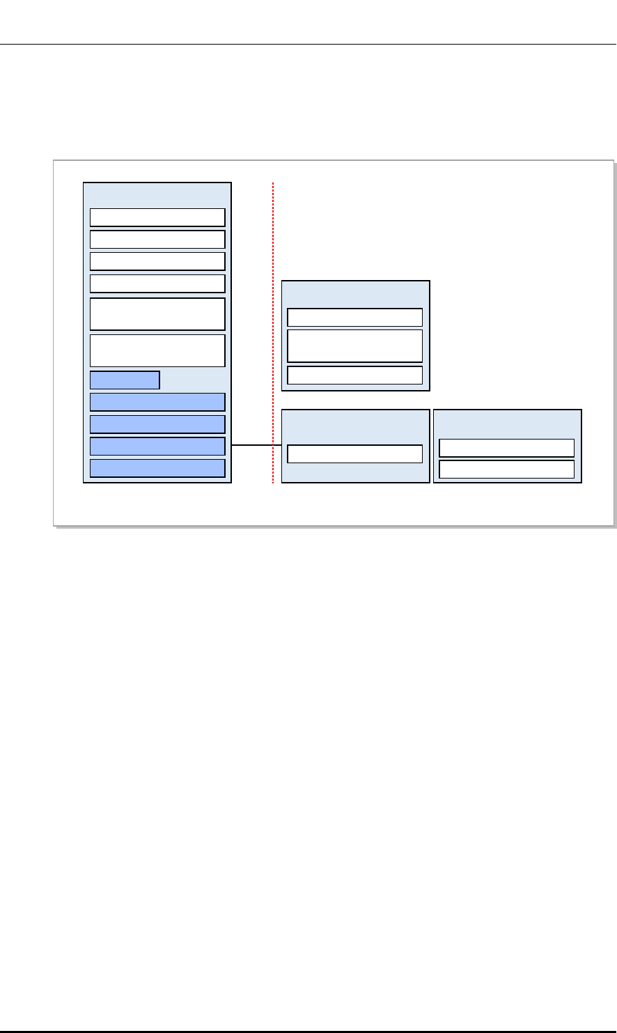
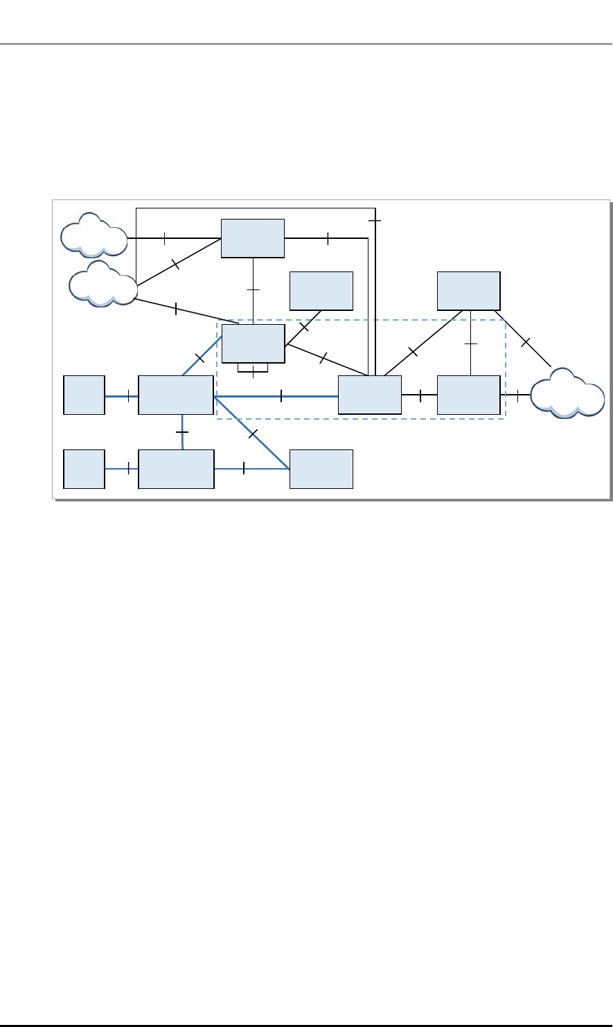
The following shows the Samsung LTE system architecture.
Figure 2. Samsung LTE System Architecture
eNB
The eNB is located between the UE and EPC. It processes packet calls by connecting to the
UE wirelessly according to the LTE air standard. The eNB is responsible for transmission
and receipt of wireless signals, modulation and demodulation of packet traffic signals,
packet scheduling for efficient utilization of wireless resources, Hybrid Automatic Repeat
request (HARQ)/ARQ processing, Packet Data Convergence Protocol (PDCP) for packet
header compression, and wireless resources control.
In addition, the eNB performs handover by interworking with the EPC.
UE
UE
OFCS
PCRF
HSS
Uu
S1-U S1-MME
EMS
CSM
eNB
eNB
EMS
LSM
OCS
EPC
S5/S8
Gx
S-GW
Sp
TL1
MME
P-GW
Gy
S11 S6a
Gz
Gz
S10
PDN
X2-C
X2-U
SNMP/FTP/UDP
© SAMSUNG Electronics Co., Ltd. page 11 of 72

Ver.
CHAPTER 1. Samsung LTE System Overview
2600-00FKQFGA2
1.0
EPC
The EPC is a system located between the eNB and PDN. The subcomponents of the EPC
are the MME, S-GW and P-GW.
MME: Processes control messages using the NAS signaling protocol with the eNB and
performs control plane functions such as UE mobility management, tracking area list
management, and bearer and session management.
S-GW: Acts as the anchor for the user plane between the 2G/3G access system and the
LTE system, and manages and changes the packet transmission layer for downlink/
uplink data.
P-GW: Allocates an IP address to the UE, acts as the anchor for mobility between the LTE
and non-3GPP access systems, and manages/changes charging and the transmission rate
according to the service level.
LTE System Manager (LSM)
The LSM provides the user interface for the operator to operate and maintain the eNB.
The LSM is responsible for software management, configuration management,
performance management and fault management, and acts as a Self-Organizing Network
(SON) server.
Core System Manager (CSM)
The CSM provides the user interface for the operator to operate and maintain the MME, S-GW,
and P-GW.
Home Subscriber Server (HSS)
The HSS is a database management system that stores and manages the parameters and
location information for all registered mobile subscribers. The HSS manages key data such
as the mobile subscriber’s access capability, basic services and supplementary services, and
provides a routing function to the subscribed receivers.
Policy and Charging Rule Function (PCRF)
The PCRF server creates policy rules to dynamically apply the QoS and charging policies
differentiated by service flow, or creates the policy rules that can be applied commonly to
multiple service flows. The P-GW includes the Policy and Charging Enforcement Function
(PCEF), which allows application of policy rules received from the PCRF to each service
flow.
Online Charging System (OCS)
The OCS collects online charging information by interfacing with S-GW and P-GW.
When a subscriber for whom online charging information is required makes a call, the P-GW
transmits and receives the subscriber’s charging information by interworking with the OCS.
© SAMSUNG Electronics Co., Ltd. page 12 of 72

Ver.
CHAPTER 1. Samsung LTE System Overview
2600-00FKQFGA2
1.0
Offline Charging System (OFCS)
The OFCS collects offline charging information by interfacing with S-GW and P-GW.
The OFCS uses the GTP’ (Gz) or Diameter (Rf) interface to interface with the S-GW and
P-GW.
© SAMSUNG Electronics Co., Ltd. page 13 of 72

Ver.
CHAPTER 2. System Overview
2600-00FKQFGA2
1.0
CHAPTER 2. System Overview
2.1 Introduction to System
Indoor Pico Cell, an LTE eNB, is located between the UE and the EPC. It provides mobile
communications services to subscribers according to the LTE air interface standard.
The Indoor Pico Cell transmits/receives radio signals to/from the UE and processes the
modulation and demodulation of packet traffic signals. The Indoor Pico Cell is also
responsible for packet scheduling and radio bandwidth allocation and performs handover
via interface with the EPC.
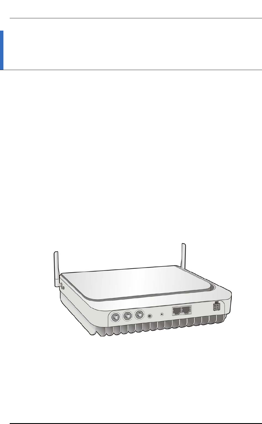
The Indoor Pico Cell can be installed vertically or horizontally; and it can be installed on
the wall, pole or rack by using the installation brackets. The Indoor Pico Cell is an all-in-
one unit. If a fault occurs, the unit must be replaced with new one.
© SAMSUNG Electronics Co., Ltd. page 14 of 72

Ver.
CHAPTER 2. System Overview
2600-00FKQFGA2
1.0
2.2 Main Functions
The main functions of the Indoor Pico Cell (hereinafter, eNB) are as follows:
Physical Layer Processing
Call Processing Function
IP Processing
SON Function
Easy Operation and Maintenance
Availability of System Features and Functions
For availability and provision schedule of the features and functions described in
the system manual, please refer to separate documentations.
2.2.1 Physical Layer Processing
The eNB transmits/receives data through the radio channel between the EPC and UE.
To do so, the eNB provides the following functions.
OFDMA/SC-FDMA Scheme
Downlink Reference Signal Creation and Transmission
Downlink Synchronization Signal Creation and Transmission
Channel Encoding/Decoding
Modulation/Demodulation
Resource Allocation and Scheduling
Link Adaptation
HARQ
Power Control
MIMO
OFDMA/SC-FDMA Scheme
The eNB performs the downlink OFDMA/uplink SC-FDMA channel processing that
supports the LTE standard physical layer. The downlink OFDMA scheme allows the
system to transmit data to multiple users simultaneously using the subcarrier allocated to
each user. Depending on the channel status and the transmission rate requested by the user,
the downlink OFDM can allocate one or more subcarriers to a specific subscriber to
transmit data.
In addition, when all sub-carriers are divided for multiple users, the eNB can select and
assign to each subscriber a sub-carrier with the most appropriate features using the
OFDMA scheme, thus to distribute resources efficiently and increase data throughput.
For uplink SC-FDMA, which is similar to OFDMA modulation and demodulation, a
© SAMSUNG Electronics Co., Ltd. page 15 of 72

Ver.
CHAPTER 2. System Overview
2600-00FKQFGA2
1.0
Discrete Fourier Transform (DFT) is applied to each subscriber in the modulation at the
transmitting side. An inverse Discrete Fourier Transform (IDFT) is applied for minimizing
the Peak to Average Power Ratio (PAPR) at the transmitting side, which allows continuous
allocation of frequency resources available for individual subscribers. As a result, the eNB
can reduce the power consumption of the UE.
Downlink Reference Signal Creation and Transmission
The UE must estimate the downlink channel to perform the coherent demodulation on the
physical channel in the LTE system. The LTE uses the OFDM/OFDMA-based methods for
transmitting and therefore the channel can be estimated by inserting the reference symbols
from the receiving terminal to the grid of each time and frequency. These reference
symbols are referred to as the downlink reference signal. The following reference signals
are defined for the LTE downlink.
Cell-specific reference signal: The cell specific reference signal is transmitted to every
subframe across the entire bandwidth of the downlink cell. It is mainly used for
channel estimation, MIMO rank calculation, MIMO precoding matrix selection and
signal strength measurement for handover.
Downlink Synchronization Signal Creation and Transmission
The synchronization signal is used for the initial synchronization when the UE starts to
communicate with the eNB. There are two types of synchronization signals: Primary
Synchronization Signal (PSS) and Secondary Synchronization Signal (SSS).
The UE can obtain the cell identity through the synchronization signal. It can obtain other
information about the cell through the broadcast channel. Since synchronization signals and
broadcast channels are transmitted in the 1.08 MHz range, which is right in the middle of
the cell’s channel bandwidth, the UE can obtain the basic cell information such as cell ID
regardless of the transmission bandwidth of the eNB.
Channel Encoding/Decoding
The eNB is responsible for channel encoding/decoding to correct the channel errors that
occurred on a wireless channel. In LTE, the turbo coding and the 1/3 tail-biting
convolutional coding are used. Turbo coding is mainly used for transmission of large data
packets on downlink and uplink, while convolutional coding is used for control information
transmission and broadcast channel for downlink and uplink.
Modulation/Demodulation
For the data received over the downlink from the upper layer, the eNB processes it through
the baseband of the physical layer and then transmits it via a wireless channel. At this time,
to transmit a baseband signal as far as it can go via the wireless channel, the system
modulates and transmits it on a specific high frequency bandwidth.
For the data received over the uplink from the UE through a wireless channel, the eNB
demodulates and changes it to the baseband signal to perform decoding.
© SAMSUNG Electronics Co., Ltd. page 16 of 72

Ver.
CHAPTER 2. System Overview
2600-00FKQFGA2
1.0
Resource Allocation and Scheduling
To support multiple accesses, the eNB uses OFDMA for downlink and SC-FDMA for
uplink. By allocating the 2-dimensional resources of time and frequency to multiple UEs
without overlay, both methods enable the eNB to communicate with multiple UEs
simultaneously.
The eNB can mux multiple UE information for the control channel and allocate signals
from multiple UEs to the same time and frequency resources, which is the orthogonal
resource allocation method using the cyclic shift function of the Zadoff-Chu sequence.
Such allocation of cell resources to multiple UEs is called scheduling and each cell has its
own scheduler for this function.
The LTE scheduler of the eNB allocates resources to maximize the overall throughput of
the cell by considering the channel environment of each UE, the data transmission volume
required, and other QoS elements. In addition, to reduce interferences with other cells, the
eNB can share information with the schedulers of other cells over the X2 interface.
Link Adaptation
The wireless channel environment can become faster or slower, better or worse depending
on various factors. The system is capable of increasing the transmission rate or maximizing
the total cell throughput in response to the changes in the channel environment, and this is
called link adaptation.
In particular, the Modulation and Coding Scheme (MCS) is used for changing the
modulation method and channel coding rate according to the channel status. If the channel
environment is good, the MCS increases the number of transmission bits per symbol using
a high-order modulation, such as 64QAM. If the channel environment is bad, it uses a low-
order modulation, such as QPSK and a low coding rate to minimize channel errors.
In addition, in the environment where MIMO mode can be used, the eNB operates in
MIMO mode to increase the peak data rate of subscribers and can greatly increase the cell
throughput.
If the channel information obtained is incorrect or modulation method of higher order or
higher coding rate than the given channel environment is used, errors may occur.
In such cases, the errors can be corrected by the HARD function.
© SAMSUNG Electronics Co., Ltd. page 17 of 72

Ver.
CHAPTER 2. System Overview
2600-00FKQFGA2
1.0
H-ARQ
The H-ARQ is a retransmission method in the physical layer, which uses the stop-and-wait
protocol. The eNB provides the H-ARQ function to retransmit or combine frames in the
physical layer so that the effects of wireless channel environment changes or interference
signal level changes can be minimized, which results in throughput improvement.
The LTE uses the Incremental Redundancy (IR)-based H-ARQ method and regards the
Chase Combining (CC) method as a special case of the IR method.
The eNB uses the asynchronous method for downlink and the synchronous method for
uplink.
Power Control
When transmitting a specific data rate, too high a power level may result in unnecessary
interferences and too low a power level may result in an increased error rate, causing
retransmission or delay. Unlike in other schemes such as CDMA, the power control is
relatively less important in LTE. Nevertheless, adequate power control can improve
performance of the LTE system.
Therefore, the UE should use adequate power levels for data transmission in order not to
interfere with nearby cells. Likewise, the power level for each UE could be controlled for
reducing the inter-cell interference level.
In the LTE downlink, the eNB can reduce inter-cell interference by transmitting data at
adequate power levels according to the location of the UE and the MCS, which results in
improvement of the entire cell throughput.
MIMO
The eNB can support the MIMO by using multiple antennas. For this purpose, the channel
card of the eNB has the baseband part to process the MIMO, and individual RF paths can
be processed separately. The eNB supports various types of the MIMO to provide the high-
performance data service.
The eNB uses multiple antennas to support the MIMO. MIMO has the following schemes.
Direction Item Description
Downlink SFBC (Space Frequency
Block Coding)
This scheme implements the space-time block coding
(STBC) on frequency instead of on time for increased
reliability of the link. The Alamouti codes are used.
SM (Spatial Multiplexing) Different data are divided to multiple antenna paths for
transmission so as to increase the peak data rate.
(Each path uses the same time/frequency resource.)
- Single User (SU)-MIMO: The SM between one eNB and
one UE to increase peak data rate for one UE.
- Open-loop SM: The SM that works without the
Precoding Matrix Indicator (PMI) feedback of the UE
when the UE’s channel is unknown or changes fast due
© SAMSUNG Electronics Co., Ltd. page 18 of 72

Ver.
CHAPTER 2. System Overview
2600-00FKQFGA2
1.0
Direction Item Description
to fast movement of the UE.
- Closed-loop SM: The SM that works with the Precoding
Matrix Indicator (PMI) feedback of the UE when the UE’s
channel is known or changes slow due to slow
movement of the UE.
Uplink UL Transmit Antenna
Selection
The 1 RF chain/2Tx antenna is used; and the eNB
notifies the UE what Tx antenna to use. (Closed-loop
selection of Tx antenna)
Multi-User (MU) MIMO
or Collaborative MIMO
The peak data rate of each UE is not increased but the
cell throughput is increased. In the uplink, two different
UEs use the same time/frequency resources for
transmitting different data at the same time. The eNB
uses a single Tx antenna for selecting two orthogonal
UEs.
2.2.2 Call Processing Function
Cell Information Transmission
In a serving cell, the eNB periodically transmits a Master Information Block (MIB) and
System Information Blocks (SIBs), which are system information, to allow the UE that
receives them to perform proper call processing.
Call Control and Air Resource Assignment
The eNB allows the UE to be connected to or disconnected from the network.
When the UE is connected to or released from the network, the eNB transmits and receives
the signaling messages required for call processing to and from the UE via the Uu interface,
and to and from the EPC via the S1 interface.
When the UE connects to the network, the eNB performs call control and resource
allocation required for service. When the UE is disconnected from the network, the eNB
collects and releases the allocated resources.
Handover
The eNB supports intra-frequency or inter-frequency handover between intra-eNB cells,
X2 handover between eNBs, and S1 handover between eNBs. It also processes signaling
and bearer for handover. At intra-eNB handover, handover-related messages are transmitted
via internal eNB interfaces; at X2 handover, via the X2 interface; at S1 handover, via the
S1 interface.
To minimize user traffic loss during X2 and S1 handovers, the eNB performs the data
forwarding function. The source eNB provides two forwarding methods to the target eNB:
direct forwarding via the X2 interface and indirect forwarding via the S1 interface.
The eNB allows the UE to receive traffic without loss through the data forwarding method
at handover.
© SAMSUNG Electronics Co., Ltd. page 19 of 72

Ver.
CHAPTER 2. System Overview
2600-00FKQFGA2
1.0
Handover Procedure
For more information on the handover procedure, see the ‘Message Flow’ section
below.
Admission Control (AC)
The eNB provides capacity-based admission control and QoS-based admission control for
a bearer setup request from the EPC so that the system is not overloaded.
Capacity-based admission control
There is a threshold for the maximum number of connected UEs (new calls/handover
calls) and a threshold for the maximum number of connected bearers that can be
allowed in the eNB. Call admission is determined depending on whether the connected
UEs and bearers exceed the thresholds.
QoS-based admission control
The eNB determines whether to admit a call depending on the estimated PRB usage of
the newly requested bearer, the PRB usage status of the bearers in service, and the
maximum acceptance limit of the PRB (per bearer type, QCI, and UL/DL).
RLC ARQ
The eNB performs the ARQ function for the RLC Acknowledged Mode (AM) only.
When receiving and transmitting packet data, the RLC transmits the SDU by dividing it
into units of RLC PDU at the transmitting side and the packet is retransmitted (forwarded)
according to the ARQ feedback information received from the receiving side for increased
reliability of the data communication.
QoS Support
The eNB receives the QoS Class Identifier (QCI) in which the QoS characteristics of the
bearer are defined and the GBR, the MBR, and the Aggregated Maximum Bit Rate (UE-
AMBR) from the EPC. It provides the QoS for the wireless section between the UE and the
eNB and the backhaul section between the eNB and the S-GW.
Via the air interface, it performs retransmission to satisfy the rate control according to the
GBR/MBR/UE-AMBR values, priority of bearer defined in the QCI, and scheduling
considering packet delay budget, and the Packet Loss Error Rate (PLER).
Via the backhaul interface, it performs QCI-based packet classification, QCI to DSCP
mapping, and marking for the QoS. It provides queuing depending on mapping results, and
each queue transmits packets to the EPC according to a strict priority, etc.
In the Element Management System (EMS), in addition to the QCI predefined in the
specifications, operator-specific QCI and QCI-to-DSCP mapping can be set.
© SAMSUNG Electronics Co., Ltd. page 20 of 72

Ver.
CHAPTER 2. System Overview
2600-00FKQFGA2
1.0
2.2.3 IP Processing
IP QoS
The eNB can provide the backhaul QoS when communicating with the EPC by supporting
the Differentiated Services (DiffServ).
The eNB supports 8 class DiffServ and mapping between the services classes of the user
traffic received from the MS and DiffServ classes. In addition, the eNB supports mapping
between the Differentiated Services Code Points (DSCP) and the 802.3 Ethernet MAC
service classes.
IP Routing
Since the eNB provides multiple Ethernet interfaces, it stores in the routing table the
information on which Ethernet interface the IP packets will be routed to. The routing table
of the eNB is configured by the operator. The method for configuring the routing table is
similar to the standard router configuration method.
The eNB supports static routing settings, but does not support dynamic routing protocols
such as Open Shortest Path First (OSPF) or Border Gateway Protocol (BGP).
Ethernet/VLAN Interface
The eNB provides Ethernet interfaces and supports the static link grouping, Virtual Local
Area Network (VLAN), and Ethernet CoS functions that comply with IEEE 802.3ad for
Ethernet interfaces. The MAC bridge function defined in IEEE 802.1D is not supported.
The eNB allows multiple VLAN IDs to be set for an Ethernet interface. To support
Ethernet CoS, it maps the DSCP value of the IP header to the CoS value of the Ethernet
header for Tx packets.
2.2.4 SON Function
The SON function supports the self-configuration, self-establishment and self-optimization
function.
Self-Configuration and Self-Establishment
Self-configuration and self-establishment enable automatic setup of radio parameters and
automatic configuration from system ‘power-on’ to ‘in-service’, which minimizes the effort
in installing the system. The detailed functions are as follows.
Self-Configuration
− Self-configuration of Initial Physical Cell Identity (PCI)
− Self-configuration of initial neighbor information
− Self-configuration of initial Physical Random Access Channel (PRACH)
information
Self-Establishment
− Automatic IP address acquisition
− Auto OAM connectivity
© SAMSUNG Electronics Co., Ltd. page 21 of 72

Ver.
CHAPTER 2. System Overview
2600-00FKQFGA2
1.0
− Automatic software and configuration data loading
− Automatic S1/X2 setup
− Self-test
Self-Optimization
PCI auto-configuration
The SON server of the LSM is responsible for allocating the initial PCI in the self-
establishment procedure of a new eNB, detecting a problem automatically, and
selecting, changing, and setting a proper PCI when a PCI collision/confusion occurs
with the neighbor cells during operation.
Automatic Neighbor Relation (ANR) optimization
The ANR function minimizes the network operator’s effort to maintain the optimal
NRT by managing the NRT dynamically depending on grow/degrow of the neighbor
cells. This function automatically configures the initial NRT of each eNB and
recognizes environment changes, such as cell grow/degrow or new eNB installation
during operation to maintain the optimal NRT. In other words, the ANR function
updates the NRT for each eNB by automatically recognizing topology changes such as
new neighbor cell or eNB installation/uninstallation and adding or removing the
Neighbor Relation (NR) to or from the new neighbor cell.
Mobility robustness optimization
The mobility robustness optimization function is the function for improving handover
performance in the eNB by recognizing the problem that handover is triggered at the
incorrect time (e.g. too early or too late) before, after, or during handover depending
on UE mobility, or handover is triggered to the incorrect target cell (handover to the
wrong cell) and then by optimizing the handover parameters according to the reasons
for the problem.
Random Access Channel (RACH) optimization
The RACH Optimization (RO) function minimizes the access delay and interference
through dynamic management of the parameters related to random access.
The RO function is divided into the initial RACH setting operation and the operation
for optimizing parameters related to the RACH. The initial RACH setting operation is
for setting the preamble signatures and the initial time resource considering the
neighbor cells. The operation for optimizing parameters related to the RACH is for
estimating the RACH resources, such as time resource and subscriber transmission
power required for random access, that change depending on time, and for optimizing
the related parameters.
© SAMSUNG Electronics Co., Ltd. page 22 of 72

Ver.
CHAPTER 2. System Overview
2600-00FKQFGA2
1.0
2.2.5 Easy Operation and Maintenance
Through interworking with the management systems (LSM, Web-EMT, and CLI), the eNB
provides the maintenance functions such as system initialization and restart, system
configuration management, management of fault/status/diagnosis for system resources and
services, management of statistics on system resources and various performance data and
security management for system access and operation.
Graphics and Text Based Console Interfaces
The LSM manages all eNBs in the network using the Database Management System
(DBMS). The eNB also interworks with the console terminal to allow the operator to
connect directly to the Network Element (NE), rather than through the LSM, and perform
the operations and maintenance.
The operator can use the graphics-based console interface (Web-EMT, Web-based Element
Maintenance Terminal) or the text-based Command Line Interface (CLI) according to user
convenience and work purposes. The operator can access the console interfaces without
additional software. For the Web-EMT, the operator can log in to the system using Internet
Explorer. For the CLI, the operator can log in to the system using the telnet or the Secure
Shell (SSH) in the command window.
The operator can perform the management of configuration and operational information,
management of fault and status, and monitoring of statistics and so on. To grow/degrow
resources or configure a neighbor list that contains relation of multiple NEs, the operator
needs to use the LSM.
Operator Authentication Function
The eNB provides the authentication and privilege management functions for the system
operators.
The operator accesses the eNB using the operator’s account and password via the CLI.
At this time, the eNB grants the operator an operation privilege in accordance with the
operator’s level.
The eNB also logs the access successes and failures for CLI, login history, and so on.
Highly-Secured Maintenance
The eNB supports the Simple Network Management Protocol (SNMP) and SSH File
Transfer Protocol (SFTP) for security during communications with the LSM, and the
Hypertext Transfer Protocol over SSL (HTTPs) and Secure Shell (SSH) during
communications with the console terminal.
Online Software Upgrade
When a software package is upgraded, the EPC can upgrade the existing package while it is
still running.
The package upgrade is done by downloading a new package activating of the new
package.
© SAMSUNG Electronics Co., Ltd. page 23 of 72

Ver.
CHAPTER 2. System Overview
2600-00FKQFGA2
1.0
The download and activation of a new package is performed using the Download menu and
Activation menu of the LSM GUI.
When upgrading the package, the service stops temporarily at the ‘change to the new
package’ step because the existing process needs to be stopped so that the new process can
start. Since the operating system does not need to be restarted, the service can be resumed
within several minutes. After upgrading the software, the eNB updates the package stored
in the internal nonvolatile storage.
Call Trace
The eNB supports the call trace function for a specific UE.
The operator can enable trace for a specific UE through the MME. The trace execution
results such as signaling messages are transmitted to the LSM.
OAM Traffic Throttling
The eNB provides the operator with the function for suppressing the OAM-related traffic
that can occur in the system using the operator command. At this time, the target OAM-
related traffic includes the fault trap messages for alarm reporting and the statistics files
generated periodically.
For the fault trap messages, the operator can suppress generation of alarms for the whole
system or some fault traps using the alarm inhibition command, consequently allowing the
operator to control the amount of alarm traffic that is generated. For the statistics files, the
operator can control the amount of statistics files by disabling the statistics collection
function for each statistics group using the statistics collection configuration command.
© SAMSUNG Electronics Co., Ltd. page 24 of 72

Ver.
CHAPTER 2. System Overview
2600-00FKQFGA2
1.0
2.3 Specifications
Key Specifications
The key specifications of the Indoor Pico Cell are as follows:
Item Specifications
Radio Specifications
FDD LTE
Operating Frequency
1.9 GHz
Channel Bandwidth
5 MHz
Peak Throughput (Mbps)
(with Category 3 UE)
DL: 31.7 Mbps (2x2 MIMO), UL: 10.1 Mbps (1x2 SIMO)
(Calculation conditions: DL 1 % PHY error, UL 1 % PHY error)
Tx Power
250 mW/Path (Total 500 mW)
Antenna Configuration
2Tx/2Rx
Backhaul
Gigabit Ethernet 1 port (Copper)
Holdover
N/A
Input Power
The power specifications of the Indoor Pico Cell are as follows:
Item
Specifications
Indoor Pico Cell
External AC adapter (100~254 VAC)
Dimensions and Weight
The dimensions and weight of the Indoor Pico Cell are as follows:
Item Specifications
Size (W
×
D
×
H) [in. (mm)]
9.06 (230) × 2.36 (60) × 10.63 (270)
Weight [lb (kg)]
7.72 (3.5) or less
GPSR Specifications
The specifications of the Indoor Pico Cell’s GPS receiver (GPSR) are as follows:
Item Specifications
Received Signal from GPS
GPS L1 Signal
Accuracy/Stability
±0.05 ppm (frequency)
© SAMSUNG Electronics Co., Ltd. page 25 of 72
Ver.
CHAPTER 2. System Overview
2600-00FKQFGA2
1.0
IEEE1588v2 Specifications
The IEEE1588v2 specifications for the Indoor Pico Cell are as follows:
Item Specifications
Clock Source
1588 Grand Master
Accuracy/Stability
±0.05 ppm (frequency)
Synchronization Accuracy of IEEE1588v2
IEEE1588v2 satisfies the synchronization accuracy under the conditions defined
in the ITU-T G.8261 Appendix VI two-way protocol (Test Case 12-17) and G.8271.
Ambient Conditions
This section describes the operating temperature, humidity level and other ambient
conditions and related standard of the Indoor Pico Cell.
Item
Range
Temperature
0~50
°
C
Humidity
5~90 % RH
Altitude
-60~1800 m
Earthquake
Richter magnitude 7.0~8.3 (Zone 4, Telcordia GR-63 CORE)
Sound Pressure Level
45 dBA or below; 3.28 ft (1.0 m) distance from the product surface
Dust Rating
IEC60529, IP2X
EMC
FCC Part 15
Safety
UL 60950
Cautions for Antenna Installation
Do not use base station's antenna within the distance of ???cm from people and
do not co-locate nor operate in conjunction with any other antenna or transmitters
for the protection of general public from exposure to radio frequency
electromagnetic fields.
© SAMSUNG Electronics Co., Ltd. page 26 of 72

Ver.
CHAPTER 2. System Overview
2600-00FKQFGA2
1.0
© SAMSUNG Electronics Co., Ltd. page 27 of 72
Ver.
CHAPTER 2. System Overview
2600-00FKQFGA2
1.0
2.4 Intersystem Interface
2.4.1 Interface Structure
The eNB provides the following interfaces for interworking between NEs.
Figure 3. Inter-System Interface Structure
Interface between eNB and UE
The eNB, in compliance with the 3GPP LTE Uu air interface standard, transmits and
receives control signals and subscriber traffic to and from the UE.
Interface between eNB and S-GW
The interface between S-GW and eNB is 3GPP LTE S1-U, and the physical access
method is GE/FE.
Interface between eNB and MME
The interface between MME and eNB is 3GPP LTE S1-MME, and the physical access
method is GE/FE.
Interface between eNB and neighbor eNB
The inter-eNB interface is 3GPP LTE X2-C/X2-U, and the physical access method is
GE/FE.
Interface between eNB and LSM
The interface between the eNB and the LSM complies with the IETF SNMPv2c/
SNMPv3 standard, the FTP/SFTP standard, and the proprietary standard of Samsung;
the physical connection method is GE/FE.
SGSN
HSS
eNB
eNB
LSM
S-GW P-GW
PCRF
CDMA
1xRTT
CDMA
eHRPD
UE
UE
MME
Iu-PS S4
LTE-Uu S1-U S5 SGi
S10
SNMP/
FTP LTE-Uu
S3
S1-MME S11
S6a Gxc Rx
Gx
Gb
X2
Operator’s
IP Service
EPC
S101
S103
© SAMSUNG Electronics Co., Ltd. page 28 of 72
Ver.
CHAPTER 2. System Overview
2600-00FKQFGA2
1.0
2.4.2 Protocol Stack
The inter-NE protocol stack of the eNB is as follows:
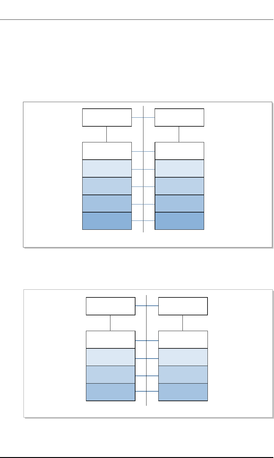
Protocol Stack between UE and eNB
The user plane protocol layer consists of the PDCP, RLC, MAC, and PHY layers.
The user plane is responsible for transmission of the user data (e.g. IP packets) received
from the upper layer. In the User plane, all protocols are terminated in the eNB.
The control plane protocol layer is composed of the NAS layer, RRC layer, PDCP layer,
RLC layer, MAC layer and PHY layer. The NAS layer is located on the upper wireless
protocol. It performs UE authentication between UE and MME, security control, and
paging and mobility management of UE in the LTE IDLE mode.
In the control plane, all protocols except for the NAS signal are terminated in the eNB.
Figure 4. Protocol Stack between UE and eNB
NAS
RRC
PDCP
RLC
MAC
L1
NAS
S1-AP
SCTP
IP
L2
L1
RRC
PDCP
RLC
MAC
L1
S1-AP
SCTP
IP
L2
L1
UE LTE-Uu eNB
Relay
MME S1-MME
© SAMSUNG Electronics Co., Ltd. page 29 of 72
Ver.
CHAPTER 2. System Overview
2600-00FKQFGA2
1.0
Protocol Stack between eNB and EPC
The eNB and the EPC are connected physically through the FE and GE method, and the
connection specification should satisfy the LTE S1-U and S1-MME interface. In the user
plane, the GTP-User (GTP-U) is used as the upper layer of the IP layer; and in the Control
plane, the SCTP is used as the upper layer of the IP layer.
The figure below shows the user plane protocol stack between the eNB and S-GW.
Figure 5. Protocol Stack between eNB and S-GW User Plane
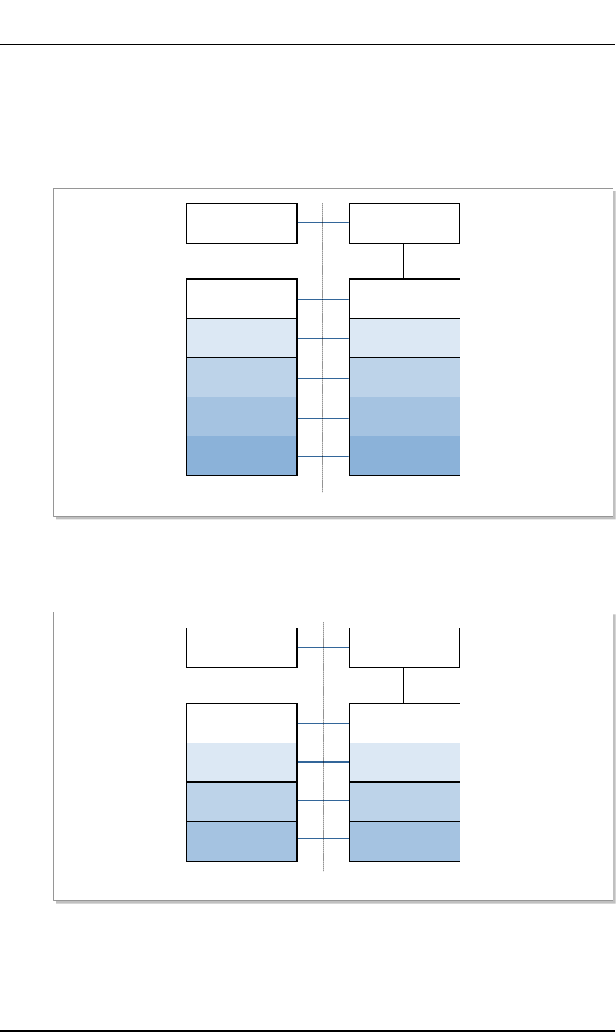
The figure below shows the control plane protocol stack between the eNB and MME.
Figure 6. Protocol Stack between eNB and MME Control Plane
S1-MME
S1-U
eNB
UDP
IP
L2
L1
S-GW
UDP
IP
L2
L1
GTP-U GTP-U
User Plane
PDUs
User Plane
PDUs
S1-MME
eNB
IP
L2
L1
MME
IP
L2
L1
SCTP SCTP
S1-AP S1-AP
© SAMSUNG Electronics Co., Ltd. page 30 of 72
Ver.
CHAPTER 2. System Overview
2600-00FKQFGA2
1.0
Inter-eNB Protocol Stack
The eNB and the eNB are connected physically through the FE and GE method, and the
connection specification should satisfy the LTE X2 interface. The figure below shows the
inter-eNB user plane protocol stack.
Figure 7. Inter-eNB User Plane Protocol Stack
The figure below shows the control plane protocol stack.
Figure 8. Inter-eNB Control Plane Protocol Stack
X2
eNB
UDP
IP
L2
L1
eNB
UDP
IP
L2
L1
GTP-U GTP-U
User Plane
PDUs
User Plane
PDUs
X2
eNB
IP
L2
L1
eNB
IP
L2
L1
SCTP SCTP
X2-AP X2-AP
© SAMSUNG Electronics Co., Ltd. page 31 of 72

Ver.
CHAPTER 2. System Overview
2600-00FKQFGA2
1.0
Protocol Stack between eNB and LSM
The FE and GE are used for the physical connection between eNB and LSM, and the
connection specifications must satisfy the FTP/SNMP interface. The figure below shows
the user plane protocol stack between the eNB and LSM.
Figure 9. Interface Protocol Stack between eNB and LSM
FTP/SNMP
eNB
IP
L2
L1
LSM
IP
L2
L1
TCP UDP
FTP SNMP
TCP UDP
FTP SNMP
© SAMSUNG Electronics Co., Ltd. page 32 of 72
Ver.
CHAPTER 3. System Structure
2600-00FKQFGA2
1.0
CHAPTER 3. System Structure
3.1 Hardware Structure
The Indoor Pico Cell consists of LTE 7 baseband and transceiver Integrated board
Assembly (L7IAs) which is the digital & RF board.
The L7IA performs the functions of main controller, network interface, clock generation &
distribution, and modem. The transceiver performs the Digital Up Conversion (DUC)/Digital
Down Conversion (DDC), Crest Factor Reduction (CFR), linearization and DAC/ADC
functions. Moreover, the L7IA performs the spurious wave suppression function and has
the built-in Low Noise Amplifier (LNA).
The L7IA operates with 1 Carrier/Omni 2Tx/2Rx. The maximum output of the L7IA is 250
mW/path for the output port.
The configuration of the Indoor Pico Cell is shown below:
Figure 10. Indoor Pico Cell Configuration
© SAMSUNG Electronics Co., Ltd. page 33 of 72
Ver.
CHAPTER 3. System Structure
2600-00FKQFGA2
1.0
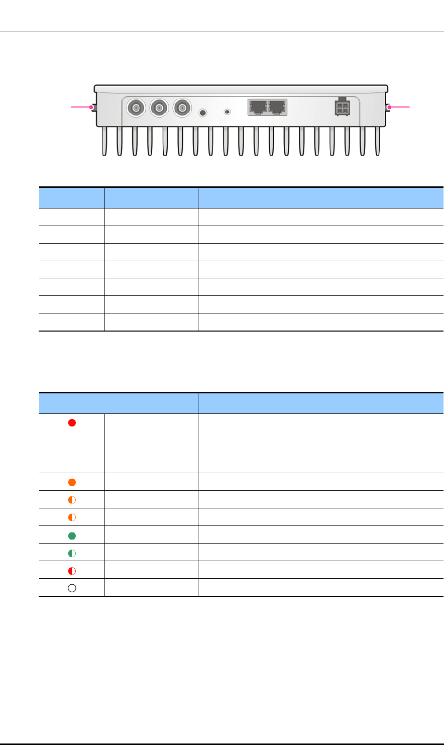
The external interface of the Indoor Pico Cell is as follows:
Figure 11. External Interface of Indoor Pico Cell
Name Connector Type Description
ANT0, ANT1
SMA
RF Antenna
GPS SMA GPS Antenna
1PPS
SMA
1 PPS Reference Clock
10M
SMA
Reference Frequency
B/H
RJ-45
Copper Backhaul (10 Base-T/100 Base-TX/1000 Base-T)
LMT
RJ-45
LMT connection or Daisy-chain connection port
PWR
Molex 4P
12 VDC power input
The Indoor Pico Cell shows the system operation status through the LED (STS). The table
below describes the LED status.
LED Status Description
Red on - Hardware is reset.
- An error occurred with the power.
- Critical alarm is generated.
- Backhaul link is down.
Orange on
Booting has been completed.
Orange blinking (slow)
ROM loader is running.
Orange blinking (fast)
The software download and status are being checked.
Green on
Software is running.
Green blinking
Normal operation
Red blinking
Major/Minor alarm is generated.
LED off No power supply
GPS
1 PPS
10M
STS
RESET
B/H LMT
PWR
ANT 0
ANT 1
© SAMSUNG Electronics Co., Ltd. page 34 of 72
Ver.
CHAPTER 3. System Structure
2600-00FKQFGA2
1.0
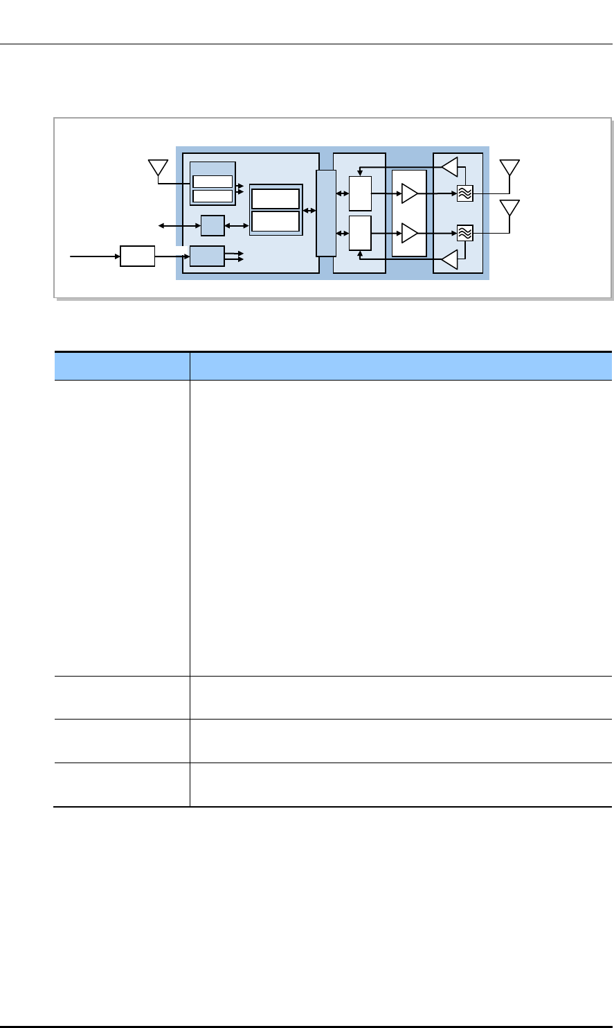
The internal configuration of the Indoor Pico Cell is shown below.
Figure 12. Internal Configuration of Indoor Pico Cell
Item Description
Digital Processing
Function
SoC function
- Performs the main processor functions of the system
- Performs the call processing, resource allocation, operation, and
maintenance functions
- Processes GTP, PDCP, OAM, RRC and RRM
- Processes RLC and MAC/PHY
- Processes OFDMA/SC-FDMA channel
- Processes subscriber data traffic
- Collects alarms and reports them to LSM
- Controls IEEE1588v2
Other digital processing functions
- Receives GPS signals and generates and supplies clocks
- Synchronizes using IEEE 1588v2 packet
- Supports backhaul (GE/FE)
Transceiver Function - Supports 5 MHz 1 Carrier/Omni 2Tx/2Rx
- Convert RF uplink/downlink
Power Amplifier
Function
- Supports 5 MHz 1 Carrier/Omni 2Tx/2Rx
- Max. output 250 + 250 mW (for the external antenna port of the enclosure)
Filter and LNA
Function
- Filters transmitted/received RF signals
- Performs LNA function for Rx signals
Main Controller Function
The main processor of the Indoor Pico Cell takes the highest role, and performs the
communication path setup between UE and EPC, system operation and maintenance, etc.
It also manages the status for all hardware/software in the Indoor Pico Cell, allocates and
manages resources, collects alarms, and reports all status information to the LSM.
Clock
Digital
Transceiver
Filter/LNA
GPS Antenna
GbE Backhaul
AC
(100~220 V)
AC
Adapter
DC 12 V
Power
(DC/DC)
GbE
PHY
Modem
Processor
GPSR
IEEE1588v2
FPGA
(Modem Interface)
RFIC
RFIC
PAM
PAM
Power
Amp
LNA
LNA
Filter
SoC
© SAMSUNG Electronics Co., Ltd. page 35 of 72

Ver.
CHAPTER 3. System Structure
2600-00FKQFGA2
1.0
Clock Generation and Distribution Function
The L7IA is equipped with Beyond Enhanced GPS Engine Module (BEGEM) and
IEEE1588v2 block. The BEGEM enables each block of the Indoor Pico Cell to operate
under a synchronized clock system.
The BEGEM creates the PP2S (Even Clock) and digital 10 MHz using the synchronization
signal received via the GPS antenna while the IEEE1588v2 block creates the 1 PPS and
digital 10 MHz synchronized with the IEEE1588v2 Master and each delivers the created
data to the Clock Generation & Distribution block of the L7IA.
The Clock Generation & Distribution block generates the system clock (30.72 MHz), PP2S
(Even clock), 1 PPS, and System Frame Number (SFN) for synchronization using the
signals received, and distributes them to the hardware blocks in the system.
The clock distributed in the system is used to keep the internal synchronization in the Pico
Cell and operate the system.
The Clock Generation & Distribution block also generates the 1PPS which is the reference
clock used for the measuring equipment or repeater. And, the BEGEM also transmits time
information and location information through the TOD path.
Network Interface Function
The L7IA interfaces with the EPC via Gigabit Ethernet or Fast Ethernet.
Subscriber Channel Processing Function
The L7IA is equipped with the modem supporting the LTE standard physical layer to
process the OFDMA/SC-FDMA channel, and the DSP processes the RLC/MAC.
The modem modulates the packet data received from upper level and transmits it to the
transceiver. Reversely, the modem demodulates the packet data received from the
transceiver, converts them to the format which is defined in the LTE standard physical
layer specifications, and transmits them to the upper processor.
2Tx/2Rx MIMO Support
The RF part of the L7IA consists of transceiver and AMP, and supports the RF path of the
2Tx/2Rx. The maximum output is 250 mW/path for the external antenna port of the
enclosure.
DAC/ADC and Power Amplification
For the downlink, the baseband signals are converted to analog signals through the Digital
to Analog Converter (DAC). The frequency of those analog signals is up converted through
the modulator and then those signals are amplified into high-power RF signals through the
power amplifier.
For the uplink, the frequency of the signals where low noise is amplified at LNA of L7IA is
down converted through the demodulator. These down-converted frequency signals are
converted to baseband signals through the Analog to Digital Converter (ADC).
The converted baseband signals are transmitted to the modem.
© SAMSUNG Electronics Co., Ltd. page 36 of 72
Ver.
CHAPTER 3. System Structure
2600-00FKQFGA2
1.0
Reset Function
The L7IA can reset the hardware remotely. The reset command is transmitted to the
system’s CPLD upon the LSM’s command, and the CPLD monitors it and resets the board
power.
Filter and LNA Function
The L7IA includes a filter and LNA, and suppresses the out-of-band spurious wave
radiation.
The L7IA supports the RF path of 2Tx/2Rx. In the downlink path of the L7IA, the high-
power amplified RF signal is transmitted to the antenna through the filter after satisfying the
spectrum mask defined for each region. In the uplink path of the L7IA, the RF signal
received via the filter is transmitted to the digital processing part of the L7IA through low-
noise amplification in the LNA.
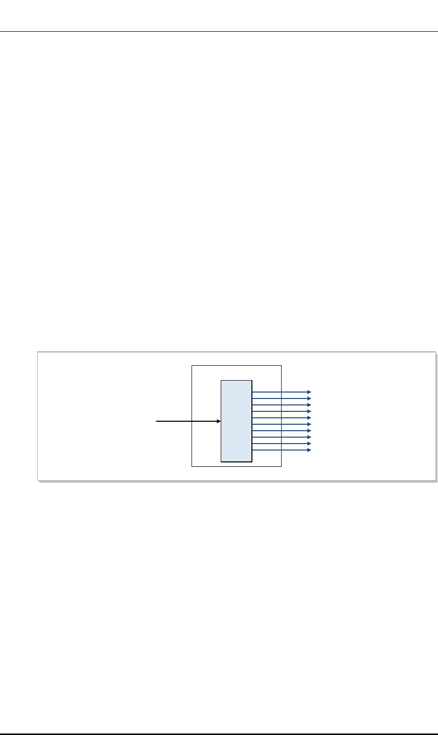
Power
The Indoor Pico Cell is supplied with power through the AC adapter. The L7IA uses the 12
VDC received via an external AC adapter. After receiving the 12 VDC power input, it
generates the power required in the L7IA through the DC/DC converter.
Figure 13. Power Supply Configuration
5.5 V
5 V
3.8 V
3.3 V
2.5 V
1.8 V
1.5 V
1.2 V
0.9 V
0.75 V
Power Block
DC/DC
Converter
AC Adaptor
(DC 12 V)
© SAMSUNG Electronics Co., Ltd. page 37 of 72
Ver.
CHAPTER 3. System Structure
2600-00FKQFGA2
1.0
3.2 Software Structure
3.2.1 Basic Software Structure
The software of the eNB is divided into three parts: Kernel Space (OS/DD), Forwarding
Space (NPC, NP) and User Space (MW, IPRS, CPS, OAM) which are described below.
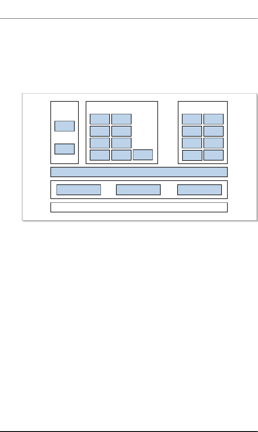
Figure 14. Indoor Pico Cell Software Structure
Operating System (OS)
The OS initializes and controls the hardware devices and ensures the software is ready to
run on the hardware devices.
The OS consists of a booter, kernel, root file system (RFS) and utility.
Booter: Performs initialization on boards. It initializes the CPU, L1/L2 Cache, UART,
and MAC and the devices such as CPLD and RAM within each board, and runs the u-
boot.
Kernel Manages the operation of multiple software processes and provides various
primitives to optimize the use of limited resources.
RFS: Stores and manages the binary files, libraries, and configuration files necessary
for running and operating the software in accordance with the File-system Hierarchy
Standard 2.2 (FHS).
Utility: Provides the functions for managing the complex programmable logic device
(CPLD), LED, watchdog, and environment and inventory information, measuring and
viewing the CPU load, and storing and managing fault information when a processor
goes down.
IPRS
IPRS
IPSS
CPS
ECMB
ECCB
SCTB
TrM
GTPB
PDCB
RLCB
MACB
OAM
PM
FM
CM
SNMP
SwM
TM
Web-EMT
MW
Transport OS DD
Hardware
OSAB
CSAB
© SAMSUNG Electronics Co., Ltd. page 38 of 72

Ver.
CHAPTER 3. System Structure
2600-00FKQFGA2
1.0
Device Driver (DD)
The DD allows applications to operate normally on devices that are not directly controlled
from the OS in the system. The DD consists of the physical DD and virtual DD.
Physical DD: Provides the interface through which an upper application can configure,
control, and monitor the external devices of the processor. (Switch device driver and
Ethernet MAC driver, etc.)
Virtual DD: For the physical network interfaces, virtual interfaces are created on the
kernel so that the upper applications may control the virtual interfaces instead of
controlling the physical network interfaces directly.
Transport
The NP is the software which processes the packets required for backhaul interface.
The functions of the NP are as follows:
Packet Rx/Tx
MAC filtering
IP packet forwarding
IP fragmentation/reassembly
VLAN termination
Middleware (MW)
The MW ensures seamless communication between OS and applications on various
hardware environments. It provides a Message Delivery Service (MDS) between
applications, Debugging Utility Service (DUS), Event Notification Service (ENS), Task
Handling Service (THS), Miscellaneous Function Service (MFS).
MDS: Provides all services related to message transmitting and receiving.
DUS: Provides the function for transmitting debugging information and command
between the applications and the operator.
ENS: Adds and manages various events such as timers, and provides the function for
transmitting an event message to the destination at the time when it is needed.
MFS: The MFS is responsible for all hardware-dependent functions, such as accessing
physical addresses of hardware devices.
THS: Provides the task creation/termination function, the task control function, and
the function for providing task information, etc.
IP Routing Software (IPRS)
The IPRS is the software that provides the IP routing and IP security function for the eNB
backhaul. The IPRS is configured with IPRS and IP Security Software (IPSS), and each of
them provide the functions as follows.
IPRS: Collects and manages the system configuration and status information necessary
for IP routing. Based on this data, the IPRS provides the function for creating routing
information.
− Managing Ethernet and VLAN-TE
− IP addresses management
− IP routing information management
© SAMSUNG Electronics Co., Ltd. page 39 of 72

Ver.
CHAPTER 3. System Structure
2600-00FKQFGA2
1.0
IPSS: Provides the QoS and security function for the IP backhaul.
− Backhaul bandwidth restriction
− QCI to DSCP mapping
− DSCP to CoS mapping
− Ciphering of backhaul traffic and integrity protection by using IPsec
3.2.2 CPS Block
The Call Processing Software (CPS) block performs the resource management of the LTE
eNB and the call processing function in the eNB defined in the 3GPP and performs the
interface function with the EPC, UE, and neighbor eNBs. The CPS consists of the eNB
control processing subsystem (ECS) which is responsible for network access and call
control functions, and the eNB Data processing Subsystem (EDS) which is responsible for
user traffic handling.
In addition, depending on the eNB functions defined in 3GPP, the ECS consists of ECMB,
ECCB, SCTB, CSAB and TrM; and the EDS consists of GTPB, PDCB, RLCB and MACB.
The following shows the CPS structure.
Stream Control Transmission protocol Block (SCTB)
The SCTB is responsible for establishing the S1 interface between the eNB and the MME,
and establishes the X2 interface between neighbor eNBs.
The major functions of the SCTB are as follows:
S1 interfacing
X2 interfacing
eNB Common Management Block (ECMB)
The ECMB performs call processing function such as the system information transmission
and the eNB overload control for each eNB and cell.
The major functions of the ECMB are as follows:
Setting/Releasing cell
Transmitting system information
eNB overload control: controls the eNB overload depending on CPU load status
Access barring control: controls the access barring parameters of SIB2
Resource measurement control: controls the measurement of the resource status in the
system, such as PRB usage and PDB
Transmission of cell load information: Inter-system X2 load information message
transmission
© SAMSUNG Electronics Co., Ltd. page 40 of 72

Ver.
CHAPTER 3. System Structure
2600-00FKQFGA2
1.0
eNB Call Control Block (ECCB)
The ECCB performs the function to control the call procedure until exit after call setup and
the call processing function for the MME and neighbor eNBs.
The major functions of the ECCB are as follows:
Radio resource management
Idle to Active status transition
Setting/changing/releasing bearer
Paging Functions
MME selection/load balancing
Call admission control
Security function
Handover control
UE measurement control
Statistics processing
Trace Management (TrM)
Call Trace function
Call Summary Log (CSL) function
GPRS Tunneling Protocol Block (GTPB)
The GTPB is the user plane call processing function of the eNB. It processes the GTP.
The major functions of the GTPB are as follows:
GTP tunnel control
GTP management
GTP data transmission
PDCP Block (PDCB)
The PDCB is the user plane call processing function of the eNB. It processes the PDCP.
The major functions of the PDCB are as follows:
Header compression or decompression (ROHC only)
Transmitting user data and control plane data
PDCP sequence number maintenance
DL/UL data forwarding at handover
Ciphering and deciphering for user data and control data
Control data integrity protection
Timer-based PDCP SDU discarding
© SAMSUNG Electronics Co., Ltd. page 41 of 72

Ver.
CHAPTER 3. System Structure
2600-00FKQFGA2
1.0
Medium Access Control Block (MACB)
The MACB is the user plane call processing function of the eNB. It processes the MAC
protocol.
The major functions of the MACB are as follows:
Mapping between the logical channel and the transport channel
Multiplexing & de-multiplexing
HARQ
Transport format selection
Priority handling between UEs
Priority handling between logical channels of one UE
Radio Link Control Block (RLCB)
The RLCB is the user plane call processing function of the eNB. It processes the RLC
protocol.
The major functions of the RLCB are as follows:
Transmission for the upper layer PDU
ARQ function used for the AM mode data transmission
RLC SDU concatenation, segmentation and reassembly
Re-segmentation of RLC data PDUs
In sequence delivery
Duplicate detection
RLC SDU discard
RLC re-establishment
Protocol error detection and recovery
CPS SON Agent Block (CSAB)
The CSAB supports the SON function which is performed in the eNB CPS.
The major functions of the CSAB are as follows:
Collection of statistics regarding the mobility robustness optimization
Collection of statistics regarding the RACH optimization
© SAMSUNG Electronics Co., Ltd. page 42 of 72

Ver.
CHAPTER 3. System Structure
2600-00FKQFGA2
1.0
3.2.3 OAM Blocks
The Operation And Maintenance (OAM) is responsible for operation and maintenance in
the eNB. The OAM is configured with PM, FM, CM, SNMP, SwM, TM, Web-EMT and
OSAB.
The major functions of the OAM are as follows:
Performance Management (PM)
PM collects and provides performance data so that the operator of the management system
can determine the performance of the LTE of eNB. The PM collects events and
performance data during system operation and transmits them to the management systems.
The main functions are as follows:
Collecting statistics data
Storing statistics data
Transmitting statistics data
Fault Management (FM)
The FM performs the fault and status management functions on the eNB’s hardware and
software. The FM applies filtering to a detected fault, notifies the management system, and
reflects the fault severity and threshold changes in the fault management.
The main functions are as follows:
Detecting faults and reporting alarms
Viewing alarms
Alarm filtering
Setting alarm severity
Setting alarm threshold
Alarm correlation
Status management and reporting
Status retrieval
Configuration Management (CM)
The CM manages the eNB configuration and parameters in PLD format and provides the
data that the software blocks need. Through the command received from SNMP/CLI/Web-
EMT, the CM provides the functions that can grow/degrow the system configuration, and
display/change the configuration data and operation parameters.
The main functions are as follows:
Retrieval and change of configuration information, and grow/degrow function
© SAMSUNG Electronics Co., Ltd. page 43 of 72

Ver.
CHAPTER 3. System Structure
2600-00FKQFGA2
1.0
Simple Network Management Protocol (SNMP)
The SNMP is an SNMP agent for supporting a standard SNMP. It performs interfacing with
the upper management systems and interoperates with the internal subagents. When
receiving a request for a standard MIB object from the LSM, the SNMP processes the
request independently. When receiving a request for a private MIB object, it transmits the
request to the corresponding internal subagent.
The main functions are as follows:
Interface with SNMP Manager
Soft Ware Management (SwM)
The SwM downloads and runs the package for each board in accordance with the file list
downloaded during the preloading procedure. The SwM monitors the software that has
been run, provides information on the running software, and supports software restart and
upgrade according to the command.
The main functions are as follows:
Downloading and installing software and data files
Reset of hardware unit and system
Status monitoring of the software unit in operation
Managing and updating the software and firmware information
Software upgrade
Inventory Management Functions
Test Management (TM)
The TM checks the internal and external connection paths of system or the validity of its
resources. The connection paths are classified into system internal IPC path and external
path to other NEs. Moreover, the TM conducts on-demand tests upon the operator’s request
and periodic tests according to the schedule set by the operator.
The main functions are as follows:
Enable/disable the Orthogonal Channel Noise Simulator (OCNS)
Setting/clearing a Model
Ping test
Measuring the Tx/Rx power
Measuring the antenna Voltage Standing Wave Ratio (VSWR)
© SAMSUNG Electronics Co., Ltd. page 44 of 72

Ver.
CHAPTER 3. System Structure
2600-00FKQFGA2
1.0
OAM SON Agent Block (OSAB)
To allow the operator of a management system to perform the LTE SON function of the
eNB, the OSAB supports the automatic configuration & installation of system information,
and automatic creation & optimization of a neighbor list. The OSAB operates on the master
OAM board.
The main functions are as follows:
System information, automatic configuration, and automatic installation
Optimizing automatic neighbor relation
Detection of PCI collision/confusion
Web-based Element Maintenance Terminal (Web-EMT)
The Web-EMT is a block used to interface with the web client of the console terminal that
uses a web browser. It operates as a web server. The Web-EMT support highly secured
Secure Sockets Layer (SSL) based HTTP communication.
The main functions are as follows:
Web server function
Interoperation with other OAM blocks for processing the command from LMT
© SAMSUNG Electronics Co., Ltd. page 45 of 72

Ver.
CHAPTER 4. Message Flow
2600-00FKQFGA2
1.0
CHAPTER 4. Message Flow
4.1 Call Processing Message Flow
Attach Procedure
The figure below shows the message flow of the Attach procedure.
© SAMSUNG Electronics Co., Ltd. page 46 of 72
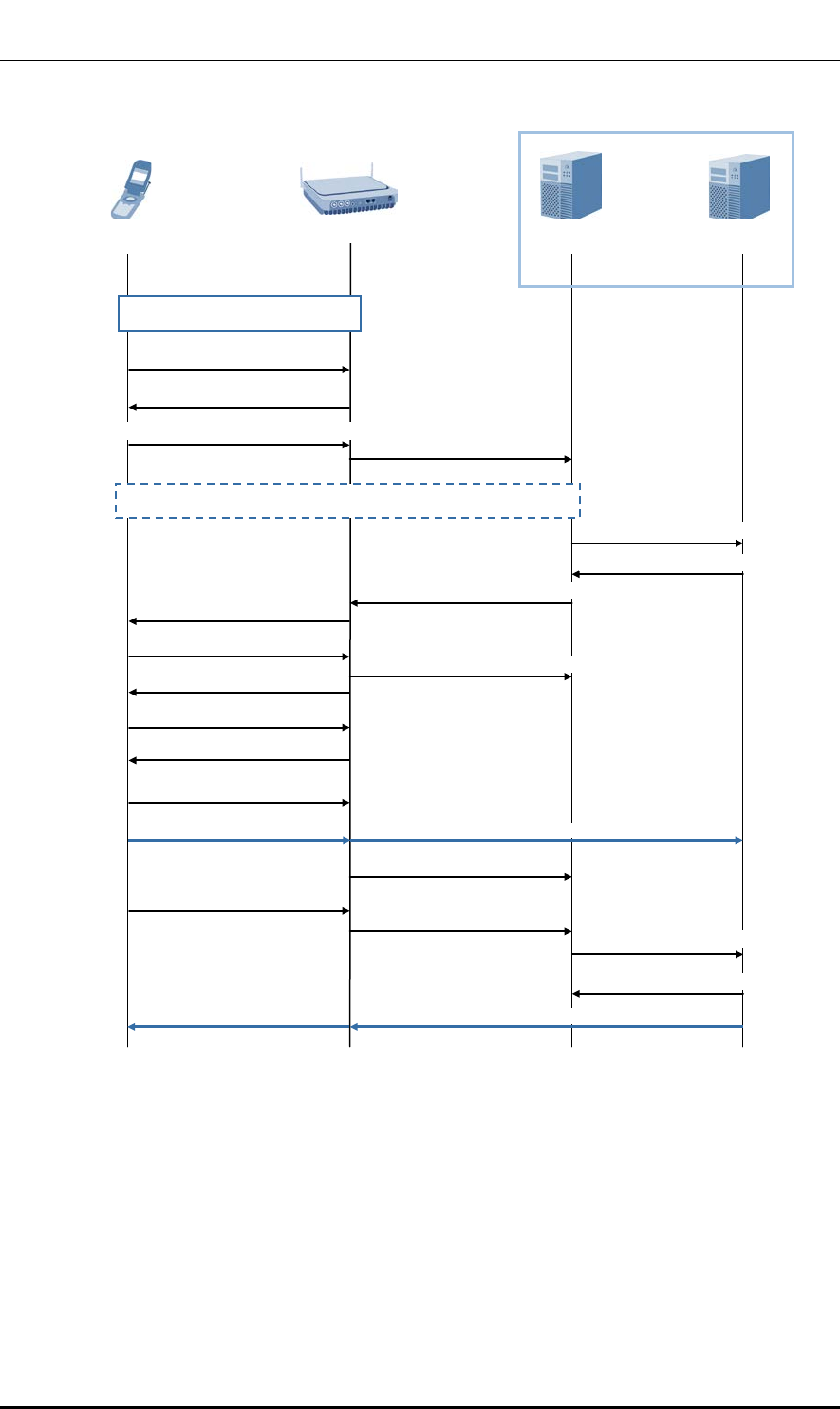
Ver.
CHAPTER 4. Message Flow
2600-00FKQFGA2
1.0
Figure 15. Attach Procedure
UE
Indoor Pico Cell
MME
S-GW
EPC
1) Random Access procedure
2) RRCConnectionRequest
3) RRCConnectionSetup
4) RRCConnectionSetupComplete
(ATTACH REQUEST)
5) INITIAL UE MESSAGE
(ATTACH REQUEST)
6) Authentication/NAS security setup
10) UECapabilityEnquiry
11) UECapabilityInformation
13) SecurityModeCommand
14) SecurityModeComplete
(ATTACH ACCEPT)
18) ULInformationTransfer
(ATTACH COMPLETE)
(ATTACH COMPLETE)
19) UPLINK NAS TRANSPORT
17) INITIAL CONTEXT SETUP
RESPONSE
(ATTACH ACCEPT)
9) INITIAL CONTEXT SETUP REQUEST
7) Create Session Request
8) Create Session Response
20) Modify Bearer Request
21) Modify Bearer Response
Downlink data
Downlink data
Uplink data
Uplink data
12) UE CAPABILITY INFO INDICATION
© SAMSUNG Electronics Co., Ltd. page 47 of 72

Ver.
CHAPTER 4. Message Flow
2600-00FKQFGA2
1.0
Step Description
1) The UE performs the random access procedure (TS 36.321, 5.1) with the Indoor Pico
Cell.
2)~4) The UE initializes the RRC Connection Establishment procedure (TS 36.331, 5.3.3).
The UE includes the NAS ATTACH REQUEST message in the RRC
RRCConnectionSetupComplete message and transmits it to the Indoor Pico Cell.
5) The Indoor Pico Cell induces the MME from the RRC factors. The Indoor Pico Cell
includes the ATTCH REQUEST message in the INITIAL UE message, which is an S1-
MME Control message, and transmits it to the MME.
6) If there is no UE context for the UE in the network, integrity is not protected for the
ATTACH REQUEST message, or the integrity check fails, authentication and NAS
security setup are always performed.
The UE performs the EPS authentication and key agreement (AKA) procedure (TS
33.401, 6.1.1) with the MME. The MME sets up an NAS security association with the
UE using the NAS security mode command (SMC) procedure (TS 33.401, 7.2.4.4).
7)~8) The MME selects the P-GW and S-GW. The MME transmits the Create Session
Request message to the S-GW The S-GW adds a record to the EPS bearer table.
From this step to step 20, the S-GW keeps the downlink packet received from the P-
GW until the Modify Bearer Request message is received. The S-GW returns the
Create Session Request message to the MME.
9)
The MME includes the ATTACH REQUEST message in the INITIAL CONTEXT SETUP
REQUEST message, which is an S1-MME Control message, and transmits it to the
Indoor Pico Cell. This S1 message also includes the AS security context information for
the UE. This information starts the AS SMC procedure at the RRC level.
10)~12) If the UE Radio Capability IE value is not contained in the INITIAL CONTEXT SETUP
REQUEST message, the Indoor Pico Cell starts the procedure for obtaining the UE
Radio Capability value from the UE and then transmits the execution result to the MME.
13)~14) The Indoor Pico Cell transmits the SecurityModeCommand message to the UE, and the
UE responds with the SecurityModeComplete message. In the Indoor Pico Cell, the
encoding downlink must start after transmitting the SecurityModeCommand and the
decoding uplink must start after receiving the SecurityModeComplete.
In the UE, the uplink encryption must be started after the SecurityModeComplete
message has been transmitted, and the downlink decryption must be started after the
SecurityModeCommand message has been received (TS 33.401, 7.2.4.5).
15)~16) The Indoor Pico Cell includes the ATTACH ACCEPT message in the
RRCConnectionReconfiguration message and transmits it to the UE. The UE transmits
the RRCConnectionReconfigurationComplete message to the Indoor Pico Cell. After
receiving the A
TTACH ACCEPT message, the UE can transmit uplink packets to both of
the S-GW and P-GW via the Indoor Pico Cell.
17) The Indoor Pico Cell transmits the INITIAL CONTEXT SETUP RESPONSE message to
the MME.
18)~19) The UE transmits the ULInformationTransfer message containing the ATTACH COMPLETE to
the Indoor Pico Cell. The Indoor Pico Cell transmits the UPLINK NAS TRANSPORT
© SAMSUNG Electronics Co., Ltd. page 48 of 72

Ver.
CHAPTER 4. Message Flow
2600-00FKQFGA2
1.0
Step Description
message containing the ATTCH COMPLETE to the MME.
20)~21) After receiving both of the INITIAL CONTEXT RESPONSE message at step 17) and
the ATTACH COMPLETE message at step 19), the MME transmits the Modify Bearer
Request message to the S-GW.
The S-GW transmits the Modify Bearer Response message to the MME. S-GW can
transmit the stored downlink packet.
© SAMSUNG Electronics Co., Ltd. page 49 of 72
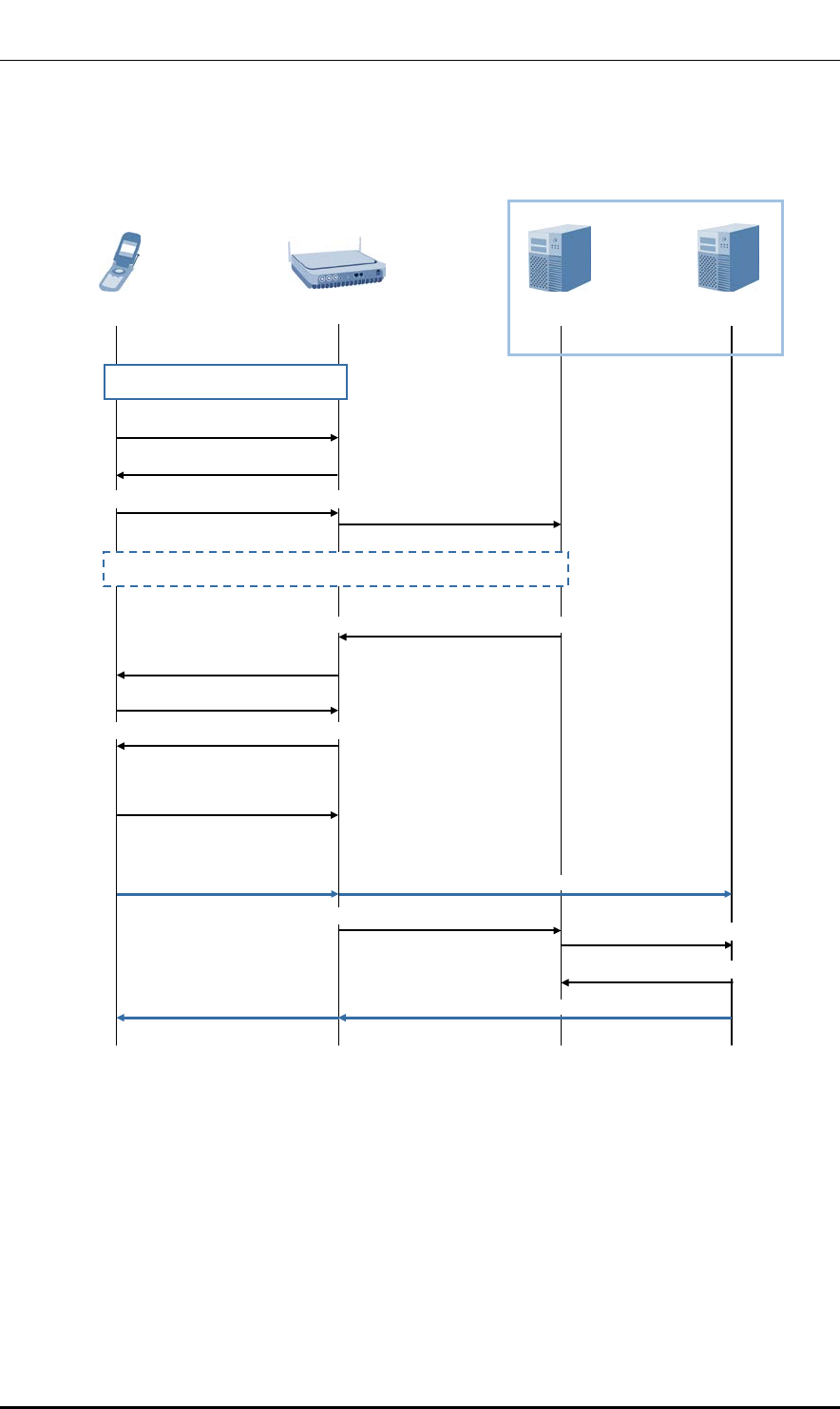
Ver.
CHAPTER 4. Message Flow
2600-00FKQFGA2
1.0
Service Request Initiated by the UE
The message flow for service request procedure by UE is illustrated below.
Figure 16. Service Request Procedure by UE
11) RRCConnectionReconfiguration Complete
UE
MME
S-GW
EPC
1) Random Access procedure
2) RRCConnectionRequest
3) RRCConnectionSetup
4) RRCConnectionSetupComplete
(SERVICE REQUEST)
5) INITIAL UE MESSAGE
(SERVICE REQUEST)
6) Authentication/NAS security setup
8) SecurityModeCommand
9) SecurityModeComplete
10) RRCConnectionReconfiguration
(SERVICE ACCEPT)
12) INITIAL CONTEXT SETUP RESPONSE
(SERVICE ACCEPT)
7) INITIAL CONTEXT SETUP REQUEST
13) Modify Bearer Request
14) Modify Bearer Response
Downlink data
Downlink data
Uplink data
Uplink data
Indoor Pico Cell
© SAMSUNG Electronics Co., Ltd. page 50 of 72

Ver.
CHAPTER 4. Message Flow
2600-00FKQFGA2
1.0
Step Description
1)
The UE performs the random access procedure with the Indoor Pico Cell.
2)~4) The UE includes the SERVICE REQUEST message (NAS) in the RRC message
transmitted to the Indoor Pico Cell and transmits it to the MME.
5) The Indoor Pico Cell includes the SERVICE REQUEST message in the INITIAL UE
message, which is an S1-AP message, and transmits it to the MME.
6) If there is no UE context for the UE in the network, integrity is not protected for the
ATTACH REQUEST message, or the integrity check fails, authentication and NAS
security setup are always performed.
The UE performs the EPS authentication and key agreement (AKA) procedure (TS
33.401, 6.1.1) with the MME. The MME sets up an NAS security association with the
UE using the NAS security mode command (SMC) procedure (TS 33.401, 7.2.4.4).
7) The MME transmits the S1-AP Initial Context Setup Request message to the Indoor
Pico Cell.
In this step, radio and S1 bearer are activated for all activated EPS bearers.
8)~11)
The Indoor Pico Cell sets up the RRC radio bearers. The user plane security is set up at
this step. The uplink data transmitted by the UE is relayed from the Indoor Pico Cell to
the S-GW. The Indoor Pico Cell transmits the uplink data to the S-GW, and then the S-
GW transmits it to the P-GW.
12) The Indoor Pico Cell transmits the S1-AP Initial Context Setup Request message to the
MME.
13)~14) The MME transmits the Modify Bearer Request message for each PDN connection to
the S-GW.
Now, the S-GW can transmit the downlink data to the UE. The S-GW transmits the
Modify Bearer Response message to the MME.
© SAMSUNG Electronics Co., Ltd. page 51 of 72
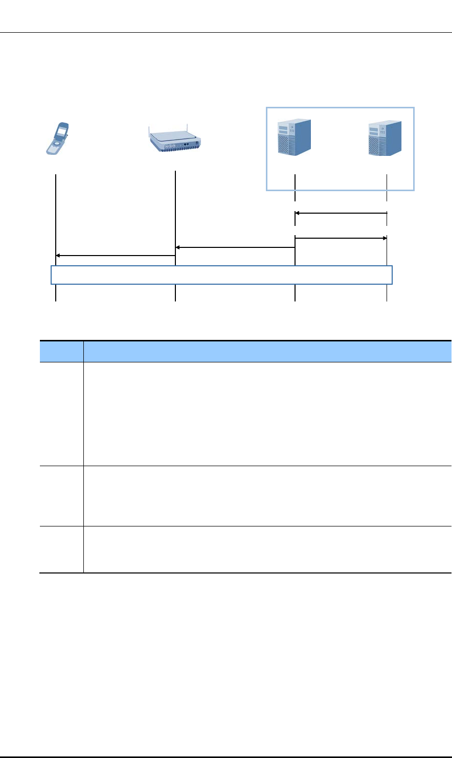
Ver.
CHAPTER 4. Message Flow
2600-00FKQFGA2
1.0
Service Request by Network
The message flow for service request procedure by network is illustrated below.
Figure 17. Service Request Procedure by Network
Step Description
1)~2) When receiving a downlink data packet that should be transmitted to a UE while the
user plane is not connected to that UE, the S-GW transmits the Downlink Data
Notification message to the MME which has the control plane connection to that UE.
The MME issues the Downlink Data Notification Acknowledge message to the S-GW in
response.
If the S-GW receives additional downlink data packet for the UE, this data packet is
stored and no new Downlink Data Notification is transmitted.
3)~4) When the UE is registered to the MME, the MME transmits the PAGING message to all
Indoor Pico Cells that belong to the TA where the UE is registered. When the Indoor
Pico Cell receives the PAGING message from the MME, the Indoor Pico Cell transmits
the Paging message to the UE.
5) If the UE in idle mode is paged via the E-UTRAN connection, the Service Request
procedure is initiated by the UE. The S-GW transmits the downlink data to the UE via
the RAT which has performed the Service Request procedure.
UE
EPC
5) UE triggered Service Request procedure
4) Paging
1) Downlink Data Notification
2) Downlink Data Notification
Acknowledge
3) PAGING
MME
S-GW
Indoor Pico Cell
© SAMSUNG Electronics Co., Ltd. page 52 of 72
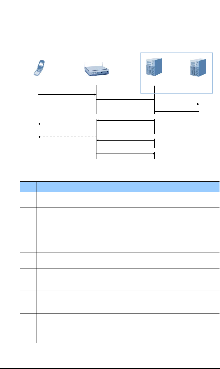
Ver.
CHAPTER 4. Message Flow
2600-00FKQFGA2
1.0
Detach by UE
The figure below shows the message flow of the Detach procedure initiated by the UE.
Figure 18. Detach Procedure by UE
Step Description
1)~2) The UE transmits the NAS DETACH REQUEST message to the MME. This NAS
message is used to start setting up an S1 connection when the UE is in Idle mode.
3) The active EPS bearers and their context information for the UE and MME which are in
the S-GW are deactivated when the MME transmits the Delete Session Request message
for each PDN connection.
4) When receiving the Delete Session Request message from the MME, the S-GW releases
the related EPS bearer context information and replies with the Delete Session Response
message.
5)~6) If the detachment procedure has been triggered by reasons other than disconnection of
power, the MME transmits the DETACH ACCEPT message to the UE.
7) The MME sets the Cause IE value of the UE CONTEXT RELEASE COMMAND message
to ‘Detach’ and transmits this message to the Indoor Pico Cell to release the S1-MME
signal connection for the UE.
8) If the RRC connection has not yet been released, the Indoor Pico Cell transmits the
RRCConnectionRelease message to the UE in Requested Reply mode. Once a reply to
this message is received from the UE, the Indoor Pico Cell removes the UE context.
9) The Indoor Pico Cell returns the UE CONTEXT RELEASE COMPLETE message to the
MME and confirms that S1 is released. By doing this, the signal connection between the
MME and Indoor Pico Cell for the UE is released. This step must be performed
immediately after step 7).
UE
MME
S-GW
EPC
1) ULInformationTransfer
3) Delete Session Request
2) UPLINK NAS TRANSPORT
(DETACH REQUEST)
4) Delete Session Response
5) DOWNLINK NAS TRANSPORT
(DETACH ACCEPT)
7) UE CONTEXT RELEASE COMMAND
9) UE CONTEXT RELEASE COMPLETE
6) DLInformationTransfer
(DETACH ACCEPT)
8) RRCConnectionRelease
(Detach)
Indoor Pico Cell
© SAMSUNG Electronics Co., Ltd. page 53 of 72

Ver.
CHAPTER 4. Message Flow
2600-00FKQFGA2
1.0
Detach by the MME
The figure below shows the message flow of the Detach procedure initiated by the MME.
Figure 19. Detach Procedure by MME
Step
Description
1)~2) The MME detaches the UE implicitly if there is no communication between them for a
long time. In case of the implicit detach, the MME does not transmit the DETACH
REQUEST message to the UE.
If the UE is in the connected state, the MME transmits the DETACH REQUEST message
to the UE to detach it explicitly.
3)~4)
It is the same procedure as step 3) and 4) of ‘Detach Procedure by UE’.
5)~6) When the UE receives the DETACH REQUEST message from the MME in Step 2), the
UE transmits the DETACH ACCEPT message to the MME. The Indoor Pico Cell
transmits this NAS message to the MME.
7) After receiving both of the DETACH ACCEPT message and the Delete Session
Response message, the MME sets the Cause IE value of the UE CONTEXT RELEASE
COMMAND message to ‘Detach’ and transmits this message to the Indoor Pico Cell to
release the S1 connection for the UE.
8)~9)
It is the same procedure as step 8) and 9) of ‘Detach Procedure by UE’.
UE
MME
S-GW
EPC
3) Delete Session Request
6) UPLINK NAS TRANSPORT
(DETACH ACCEPT)
4) Delete Session Response
1) DOWNLINK NAS TRANSPORT
(DETACH REQUEST)
7) UE CONTEXT RELEASE COMMAND
(Detach)
9) UE CONTEXT RELEASE COMPLETE
2) DLInformationTransfer
(DETACH REQUEST)
8) RRCConnectionRelease
5) ULInformationTransfer
(DETACH ACCEPT)
Indoor Pico Cell
© SAMSUNG Electronics Co., Ltd. page 54 of 72
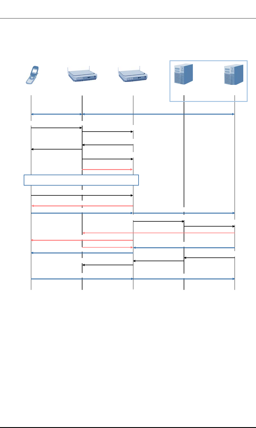
Ver.
CHAPTER 4. Message Flow
2600-00FKQFGA2
1.0
LTE Handover: X2 Based Handover
The message flow for X2 based handover procedure is illustrated below.
Figure 20. X2 Based Handover Procedure
UE
Source Indoor
Pico Cell
MME
S-GW
EPC
1) MeasurementReport
Target Indoor
Pico Cell
Downlink/Uplink data
Downlink/Uplink data
3) HANDOVER REQUEST ACKNOWLEDGE
5) SN STATUS TRANSFER
4) RRCConnection-
Reconfiguration
(mobilityControlinfo)
Data forwarding
6) Synchronization/UL allocation and timing advance
7) RRCConnectionReconfigurationComplete
Forwarded data
Uplink data
Forwarded data
Downlink data
Down/Uplink data
Down/Uplink data
Uplink data
Downlink data
8) PATH SWITCH REQUEST
9) Modify Bearer Request
End marker
End marker
10) Modify Bearer Response
11) PATH SWITCH
REQUEST
ACKNOWLEDGE
12) UE CONTEXT RELEASE
2) HANDOVER REQUEST
© SAMSUNG Electronics Co., Ltd. page 55 of 72

Ver.
CHAPTER 4. Message Flow
2600-00FKQFGA2
1.0
Step Description
1) The UE transmits the MessurementReport message according to the system
information, standards and rules. The source Indoor Pico Cell determines whether to
perform the UE handover based on the MeasurementReport message and the radio
resource management information.
2) The source Indoor Pico Cell transmits the HANDOVER REQUEST message and the
information required for handover to the target Indoor Pico Cell. The target Indoor Pico
Cell can perform management control in accordance with the E-RAB QoS information
received.
3)~4) The target Indoor Pico Cell creates the RRCConnectionReconfiguration message which
contains the mobileControlInfo IE for preparing and executing the handover. The target
Indoor Pico Cell includes the RRCConnectionReconfiguration message in the
HANDOVER REQUEST ACKNOWLEDGE message, and transmits it to the source
Indoor Pico Cell.
The source Indoor Pico Cell transmits the RRCConnectionReconfiguration message
and the necessary parameters to the UE to command it to perform the handover.
5) To transmit the uplink PDCP SN receiver status and the downlink PDCP SN transmitter
status of the E-RABs of which the PDCP status must be preserved, the source Indoor
Pico Cell transmits the SN STATUS TRANSFER message to the target Indoor Pico Cell.
6) After receiving the RRCConnectionReconfiguration message containing
mobileControlInfo IE, the UE performs synchronization with the target Indoor Pico Cell
and connects to the target cell via a RACH. The target Indoor Pico Cell responds with
UL allocation and a timing advance value.
7) After successfully connecting to the target cell, the UE uses the RRCConnection-
ReconfigurationComplete message to notify the target Indoor Pico Cell that the
handover procedure is complete.
8) The target Indoor Pico Cell uses the PATH SWITCH REQUEST message to notify the
MME that the UE has changed the cell.
9)~10) The MME transmits the Modify Bearer Response message to the S-GW. The S-GW
changes the downlink data path into the target Indoor Pico Cell. The S-GW transmits at
least one ‘end marker’ to the source Indoor Pico Cell through the previous path, and
releases the user plane resources for the source Indoor Pico Cell.
The S-GW transmits the Modify Bearer Response message to the MME.
11) The MME transmits the PATH SWITCH REQUEST ACKNOWLEDGE message to
acknowledge the PATH SWITCH REQUEST message.
12) The target Indoor Pico Cell transmits the UE CONTEXT RELEASE message to the
source Indoor Pico Cell to notify the handover has succeeded and to make the source
Indoor Pico Cell release its resources. If the source Indoor Pico Cell receives the UE
CONTEXT RELEASE message, it releases the radio resources and the control plane
resources related to the UE context.
© SAMSUNG Electronics Co., Ltd. page 56 of 72
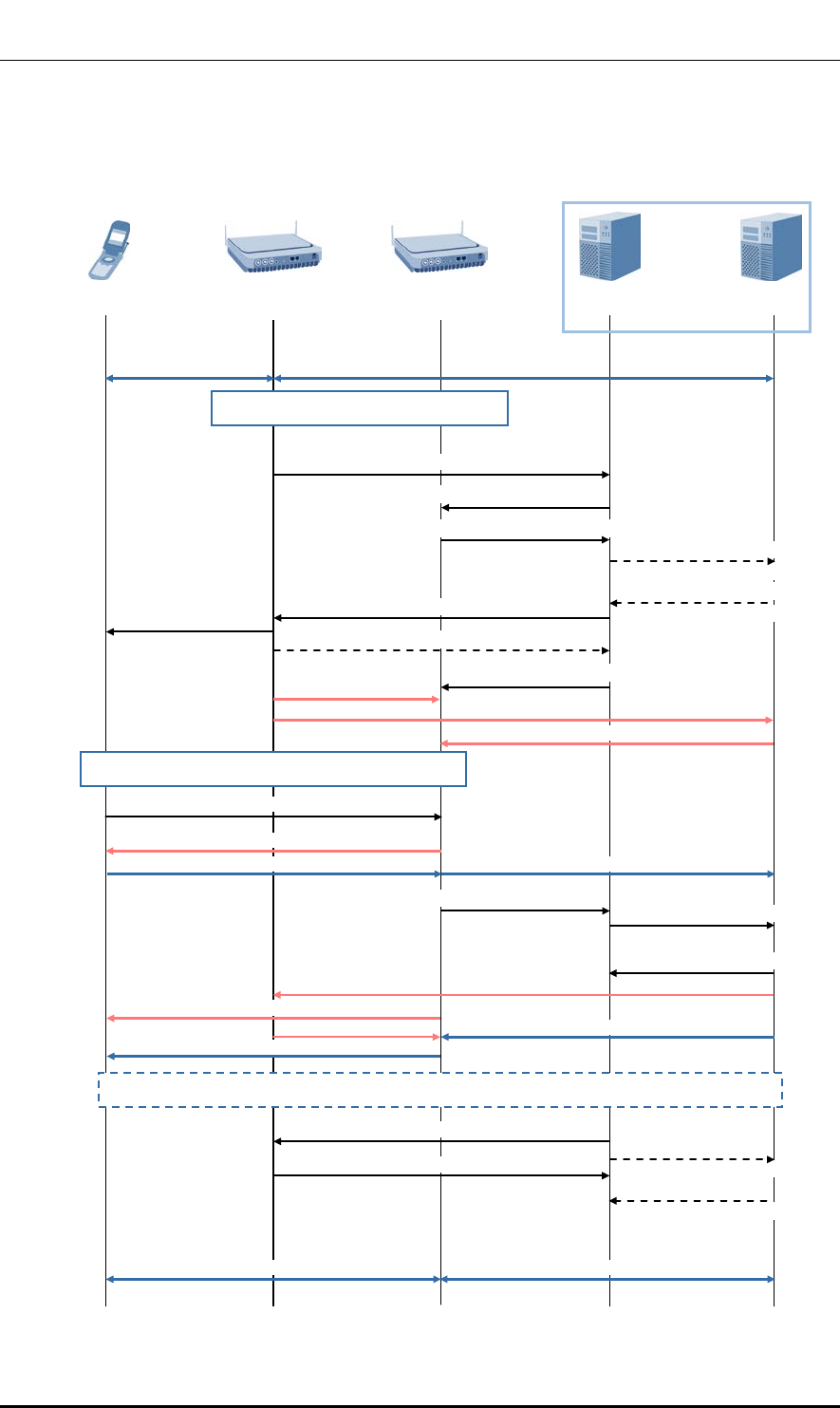
Ver.
CHAPTER 4. Message Flow
2600-00FKQFGA2
1.0
LTE Handover: S1-based Handover
The message flow for S1 based handover procedure is illustrated below.
Figure 21. S1-based Handover Procedure
UE
Source Indoor
Pico Cell
MME
S-GW
EPC
Target Indoor
Pico Cell
Downlink/Uplink data
Downlink/Uplink data
3) HANDOVER REQUEST
5) Create Indirect Data
Forwarding Tunnel Request
8) RRCConnection-
Reconfiguration
(mobilityControlinfo)
1) Direct data forwarding
1) Decision to trigger a relocation via S1
2) HANDOVER REQUIRED
Indirect data forwarding
Downlink data
Downlink data
End marker
End marker
6) Create Indirect Data
Forwarding Tunnel Response
7) HANDOVER COMMAND
9) eNB STATUS TRANSFER
10) MME STATUS TRANSFER
2) Indirect data forwarding
11) Detach from old cell/Synchronize to new cell
12) RRCConnectionReconfigurationComplete
Forwarded data
Uplink data
Uplink data
13) HANDOVER NOTIFY
14) Modify Bearer Request
15) Modify Bearer Response
Forwarded data
16) Tracking Area Update procedure
17) UE CONTEXT RELEASE COMMAND
18) UE CONTEXT RELEASE COMPLETE
19) Delete Indirect Data
Forwarding Tunnel Request
20) Delete Indirect Data
Forwarding Tunnel Response
Downlink/Uplink data
Downlink/Uplink data
4) HANDOVER REQUEST
ACKNOWLEDGE
© SAMSUNG Electronics Co., Ltd. page 57 of 72

Ver.
CHAPTER 4. Message Flow
2600-00FKQFGA2
1.0
Step Description
1) The source Indoor Pico Cell determines whether to perform S1-based handover to the
target Ind
oor Pico Cell. The source Indoor Pico Cell can make this decision if there is no
X2 connection to the target Indoor Pico Cell or if an error is notified by the target Indoor
Pico Cell after an X2-based handover has failed, or if the source Indoor Pico Cell
dynamically receives the related information.
2) The target Indoor Pico Cell transmits the HANDOVER REQUIRED message to the
MME.
The source Indoor Pico Cell notifies the target Indoor Pico Cell which bearer is used for
data forwarding and whether direct forwarding from the source Indoor Pico Cell to the
target Indoor Pico Cell is possible.
3)~4)
The MME transmits the HANDOVER REQUEST message to the target Indoor Pico Cell.
This message makes the target Indoor Pico Cell create a UE context containing the
bearer-related information and the security context.
The target Indoor Pico Cell transmits the HANDOVER REQUEST ACKNOWLEDGE
message to the MME.
5)~6) If indirect forwarding is used, the MME transmits the Create Indirect Data Forwarding
Tunnel Request message to the S-GW. The S-GW responds to the MME with the
Delete Indirect Data Forwarding Tunnel Response message.
7)~8) The MME transmits the HANDOVER COMMAND message to the source Indoor Pico
Cell.
The source Indoor Pico Cell creates the RRCConnectionReconfiguration message
using the Target to Source Transparent Container IE encapsulated in the HANDOVER
COMMAND message and then transmits it to the UE.
9)~10) To transmit the PDCP and HFN status of the E-RABs of which the PDCP status must be
preserved, the source Indoor Pico Cell transmits the eNB/MME STATUS TRANSFER
message to the target Indoor Pico Cell via the MME. The source Indoor Pico Cell must
start forwarding the downlink data to the target Indoor Pico Cell through the bearer
which was determined to be used for data forwarding. This can be either direct or
indirect forwarding.
11) The UE performs synchronization with the target Indoor Pico Cell and connects to the
target cell via the RACH.
The target Indoor Pico Cell responds with UL allocation and a timing advance value.
12) After successfully synchronizing with the target cell, the UE uses the
RRCConnectionReconfigurationComplete message to notify the target Indoor Pico Cell
that the handover procedure is complete. The downlink packets retransmitted by the
source Indoor Pico Cell can be forwarded to the UE. The uplink packets can also be
transmitted from the UE to the S-GW via the target Indoor Pico Cell.
13) The target Indoor Pico Cell transmits the HANDOVER NOTIFY message to the MME.
The MME starts the timer which tells when the source Indoor Pico Cell resources and
the temporary resources used for indirect forwarding at S-GW will be released.
14) The MME transmits the Modify Bearer Request message for each PDN connection to
the S-GW. Downlink packets are transmitted immediately from the S-GW to the target
Indoor Pico Cell.
© SAMSUNG Electronics Co., Ltd. page 58 of 72

Ver.
CHAPTER 4. Message Flow
2600-00FKQFGA2
1.0
Step Description
15) The S-GW transmits the Modify Bearer Response message to the MME. If the target
Indoor Pico Cell changes the path for assisting packet resorting, the S-GW immediately
transmits at least one ‘end marker’ packet to the previous path.
16) If any of the conditions listed in section 5.3.3.0 of TS 23.401(6) are met, the UE starts
the Tracking Area Update procedure.
17)~18) When the timer started at step 13) expires, the MME transmits the UE CONTEXT
RELEASE COMMAND message to the source Indoor Pico Cell. The source Indoor Pico
Cell releases the resources related to the UE and replies with the UE CONTEXT
RELEASE COMPLETE message.
19)~20) If indirect forwarding is used and when the timer started by the MME at step 13)
expires, the MME transmits the Delete Indirect Data Forwarding Tunnel Request
message to the S-GW.
This message makes the S-GW release the temporary resources allocated for indirect
forwarding at step 5).
The S-GW responds to the MME with the Delete Indirect Data Forwarding Tunnel
Response message.
© SAMSUNG Electronics Co., Ltd. page 59 of 72
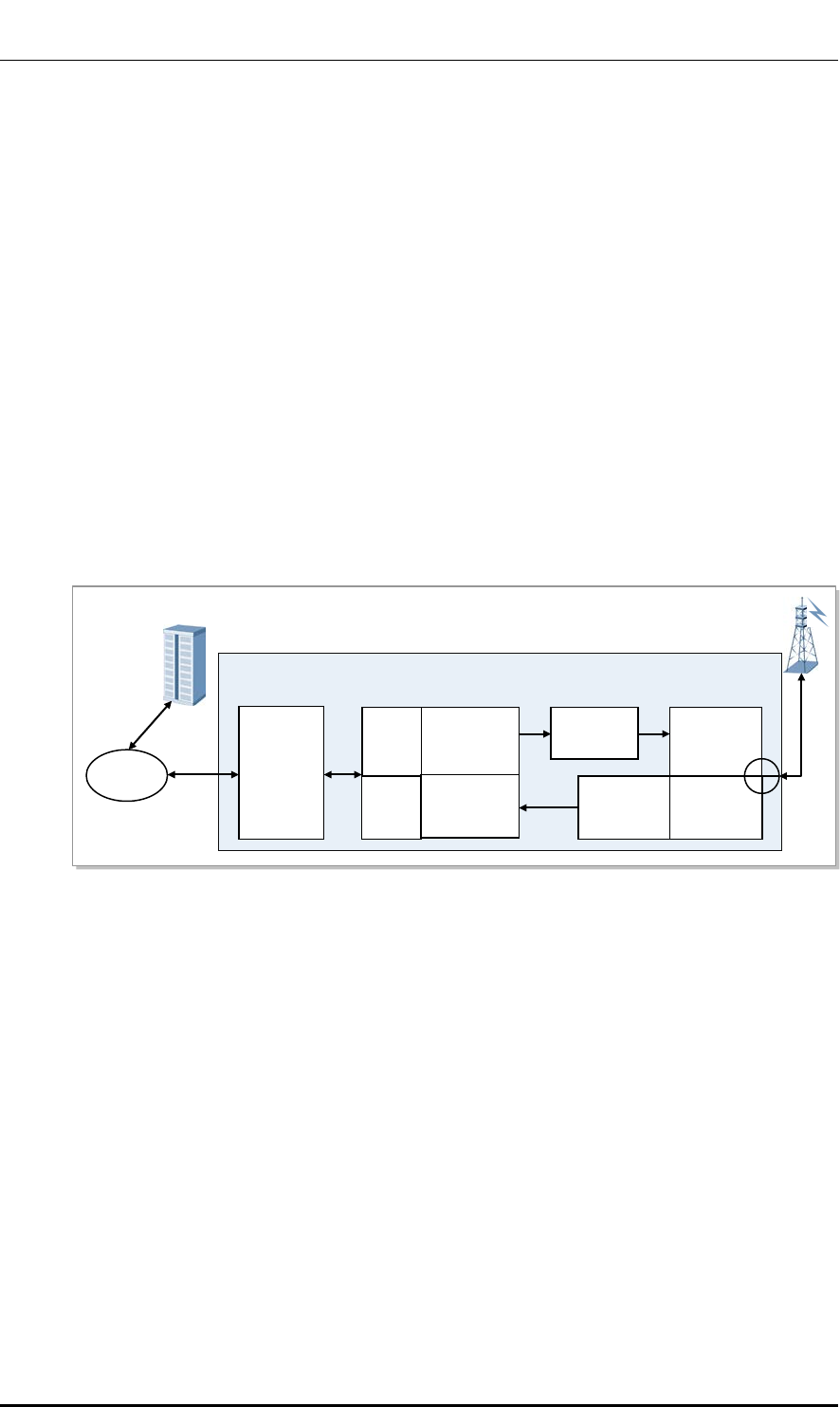
Ver.
CHAPTER 4. Message Flow
2600-00FKQFGA2
1.0
4.2 Data Traffic Flow
Sending Path
The user data received from the EPC passes through the network interface module and is
transmitted through the Ethernet switch to the L7IA of Indoor Pico Cell. The transmitted
user data goes through baseband-level digital processing, and transmitted to the transceiver
part. The transceiver up-converts the wideband baseband signal to the RF band, and the
converted signal is transmitted to the antenna through the power amplifier and filter.
Receiving Path
The RF signal received by the antenna passes through the L7IA’s filter and its low noise is
amplified by the LNA. This signal is converted to the data signal of baseband after the RF
down-conversion in the transceiver of the L7IA. The data which passed through the SC-
FDMA signaling process in the modem is converted to the Gigabit Ethernet frame and
transmitted to the EPC through GE.
Figure 22. Data Traffic Flow
Main
Processor
&
Modem
Digital
EPC
Transceiver
PAM
Filter/LNA
IP
Network
GE
D/A
A/D
UP
Conversion
Down
Conversion
Power
Amp
LNA
Tx
Filter
Rx
Filter
Indoor Pico Cell
© SAMSUNG Electronics Co., Ltd. page 60 of 72
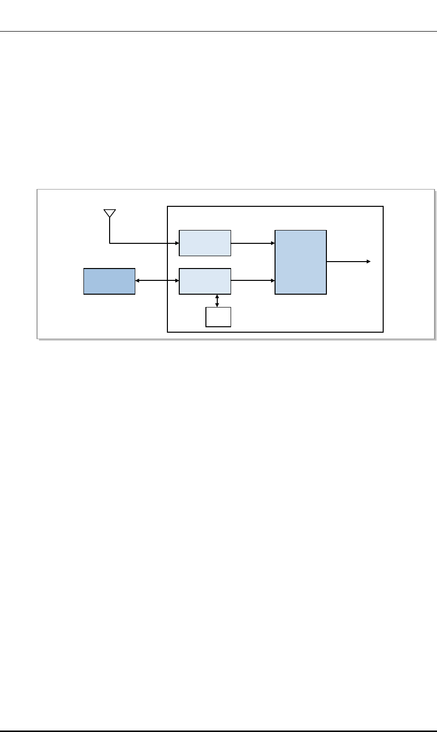
Ver.
CHAPTER 4. Message Flow
2600-00FKQFGA2
1.0
4.3 Network Sync Flow
The Indoor Pico Cell supports the GPS and IEEE1588v2 synchronization method
selectively. In case of the GPS synchronization, the GPS receiver (BEGEM) receives the
synchronization signal from the GPS and creates clocks. The clocks are distributed by the
clock generation & distribution part.
In case of the IEEE1588v2 packet synchronization, the IEEE1588v2 packet is received
from an external IEEE 1588v2 server for the synchronization.
Figure 23. Network Synchronization Flow
GPS Antenna
GPS
Receiver
IEEE1588v2
Module
Clock
Generation
&
Distribution
IEEE1588v2
Server
SoC
GPS L1 signal
PTP packet
Ethernet
Backhaul
10 MHz
PP2S
10 MHz
1 PPS
System Clock
1 PPS
Indoor Pico Cell
© SAMSUNG Electronics Co., Ltd. page 61 of 72

Ver.
CHAPTER 4. Message Flow
2600-00FKQFGA2
1.0
4.4 Alarm Signal Flow
An alarm is reported as an alarm signal when a fault occurs. The L7IA collects all the
alarms and report them to the LSM which is the management system.
Figure 24. Alarm flow
Alarm
Indoor Pico Cell
LSM
L7IA
© SAMSUNG Electronics Co., Ltd. page 62 of 72
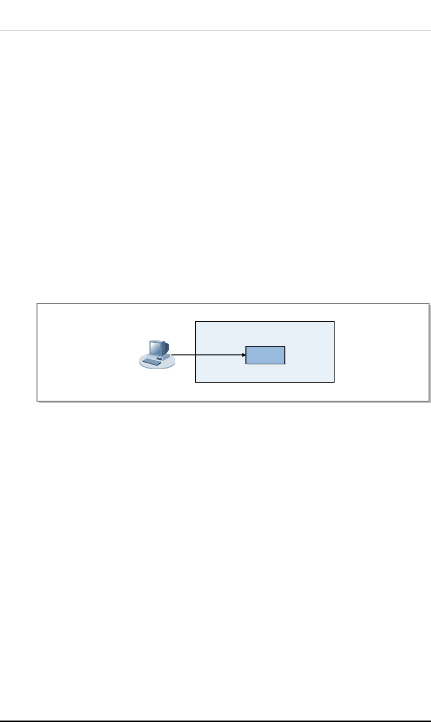
Ver.
CHAPTER 4. Message Flow
2600-00FKQFGA2
1.0
4.5 Loading Flow
Loading is the procedure through which the processors and devices of the system can
download from the LSM the software executables, data, and other elements required to
perform their functions.
Loading the system is performed during the system initialization procedure. Loading is also
involved when a specific board is mounted in the system, when a hardware reset is carried
out, or when the operator of an upper management system restarts a specific board.
At the first system initialization, the system is loaded through the LSM. As the loading
information is stored in the internal storage, no unnecessary loading is carried out afterward.
After the first system initialization, it compares the software files and versions of LSM and
downloads changed software files.
The loading information contains the software image and default configuration information
file, etc.
Figure 25. Loading Signal Flow
Indoor Pico Cell
LSM
L7IA
© SAMSUNG Electronics Co., Ltd. page 63 of 72
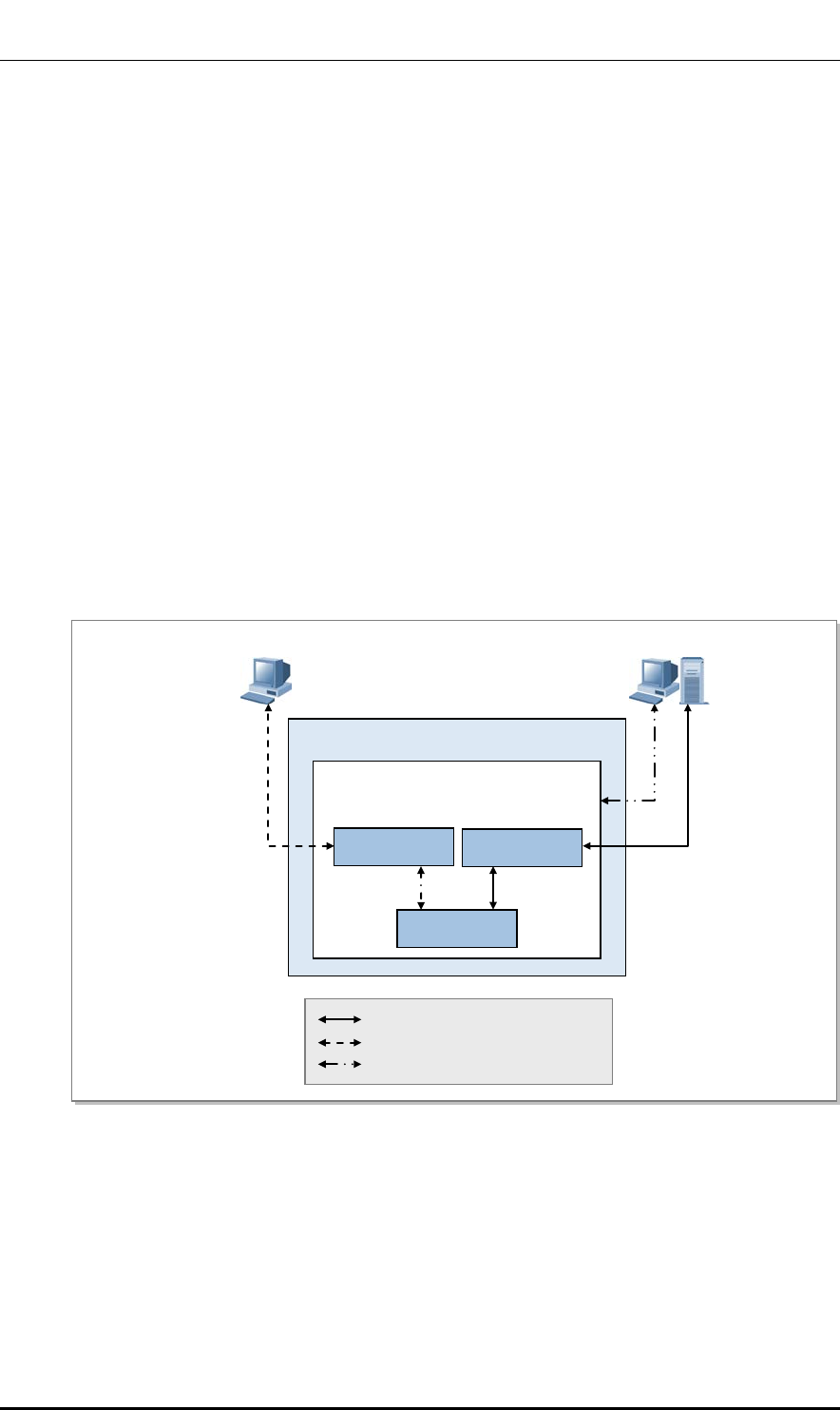
Ver.
CHAPTER 4. Message Flow
2600-00FKQFGA2
1.0
4.6 Operation and Maintenance Message Flow
The operator can check and change the status of the Indoor Pico Cell through the
management system.
To accomplish this, the Indoor Pico Cell provides the SNMP agent function, and the LSM
operator can carry out the operation and maintenance functions of the Indoor Pico Cell
remotely through the SNMP. Moreover, the operator can carry out the maintenance
function using the web browser.
The statistical information provided by the Indoor Pico Cell is given to the operator in
accordance with the collection interval.
The operation and maintenance in the Indoor Pico Cell is performed using the SNMP
message between the SNMP agent in the main OAM and the SNMP manager of the LSM.
The LMT is a type of GUI-based console terminal which directly accesses the Indoor Pico
Cell to monitor the status of, operate and maintain the equipment.
The figure below shows the operation and maintenance signal flow.
Figure 26. Operation and Maintenance Signal Flow
Indoor Pico Cell
L7IA
HTTP Server
SNMP
Other Blocks
LSM (SNMP Manager)
LMT
SNMP message
HTTP message (command/response)
Statistical Data
© SAMSUNG Electronics Co., Ltd. page 64 of 72
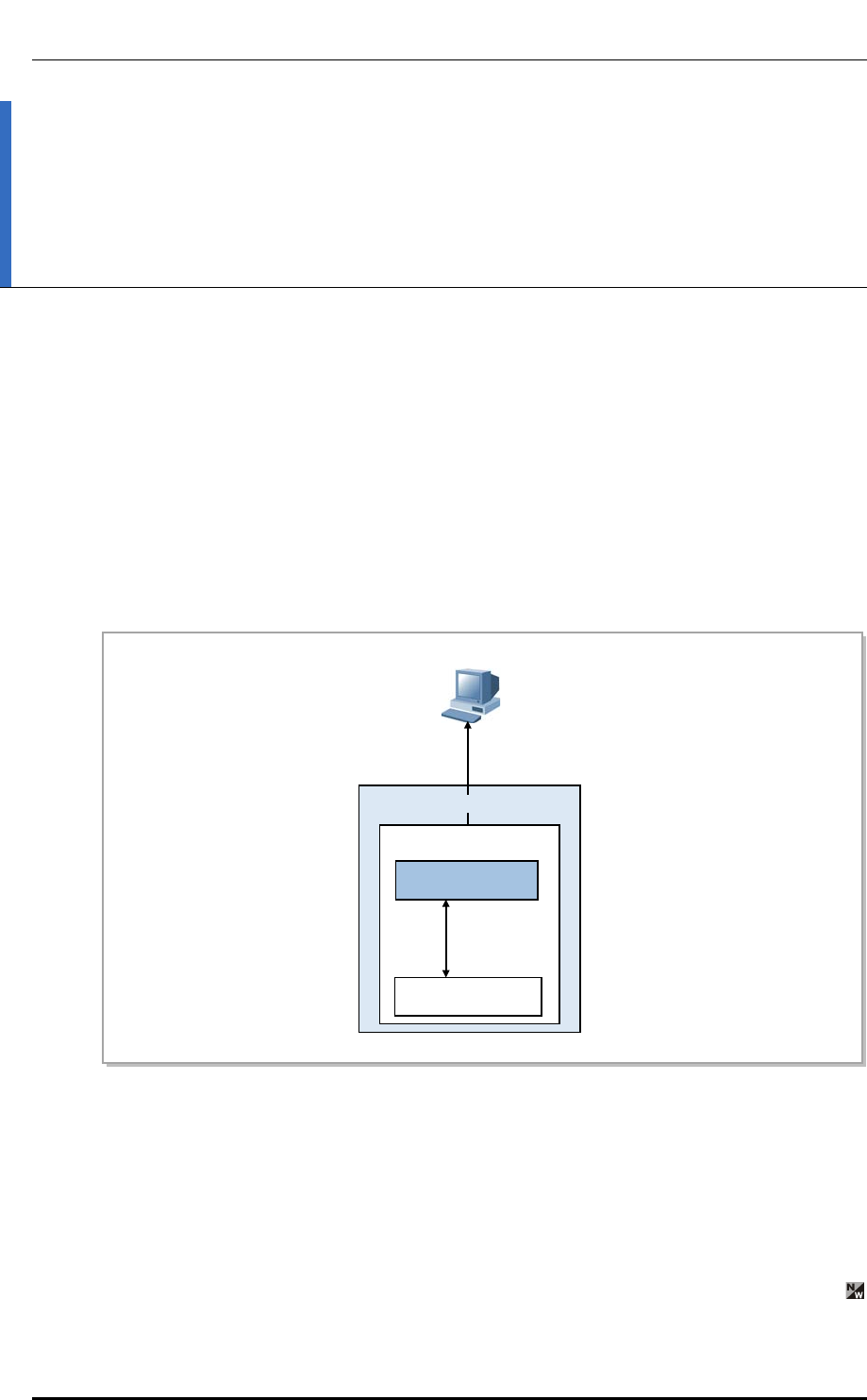
Ver.
CHAPTER 5. Supplementary Functions and Tools
2600-00FKQFGA2
1.0
CHAPTER 5. Supplementary
Functions and Tools
5.1 LMT
The LMT is a GUI-based console terminal. It is the tool that monitors the status of devices
and performs operation and maintenance tasks by connecting directly to the Indoor Pico
Cell. The operator can run the LMT using Internet Explorer, without installing separate
software. The GUI is provided using the HTTPs protocol internally.
Figure 27. LMT Interface
Through the LMT, the operator can reset or restart the Indoor Pico Cell or its internal
boards, view and change the configuration and operation parameter values, monitor the
system status and faults, carry out diagnostic functions, and so on. But the resource grow
and degrow functions and changing the operation information related to neighbor list are
available from the LSM only, which manages the entire networks and the loading images.
LMT
L7IA
HTTP Server
Other Blocks
OAM
command/
response
HTTP message
Indoor Pico Cell
© SAMSUNG Electronics Co., Ltd. page 65 of 72

Ver.
ABBREVIATION
2600-00FKQFGA2
1.0
ABBREVIATION
3GPP 3rd Generation Partnership Project
64 QAM 64 Quadrature Amplitude Modulation
A
AC Admission Control
ADC Analog to Digital Converter
AKA Authentication and Key Agreement
AM Acknowledged Mode
AMBR Aggregated Maximum Bit Rate
ANR Automatic Neighbor Relation
ARQ Automatic Repeat Request
AS Access Stratum
B
BEGEM Beyond Enhanced GPS Engine Module
BGP Border Gateway Protocol
C
CA Carrier Aggregation
C & M Control & Maintenance
CC Chase Combining
CFR Crest Factor Reduction
CLI Command Line Interface
CM Configuration Management
CoS Class of Service
CPLD Complex Programmable Logic Device
CPS Call Processing Software
CS Circuit Service
CSAB CPS SON Agent Block
CSM Core System Manager
© SAMSUNG Electronics Co., Ltd. page 66 of 72

Ver.
ABBREVIATION
2600-00FKQFGA2
1.0
D
DAC Digital to Analog Converter
DBMS Database Management System
DD Device Driver
DDC Digital Down Conversion
DFT Discrete Fourier Transform
DHCP Dynamic Host Configuration Protocol
DiffServ Differentiated Services
DL Downlink
DSCP Differentiated Services Code Point
DSP Digital Signal Processor
DUC Digital Up Conversion
DUS Debugging Utility Service
E
ECCB eNB Call Control Block
ECMB eNB Common Management Block
ECS eNB Control processing Subsystem
EDS eNB Data processing Subsystem
EMC Electromagnetic Compatibility
EMI Electromagnetic Interference
EMS Element Management System
eNB evolved UTRAN Node-B
ENS Event Notification Service
E/O Electric-to-Optic
EPC Evolved Packet Core
EPS Evolved Packet System
ES Energy Saving
ESM Energy Saving Management
ESM EPC System Manager
E-UTRAN Evolved UTRAN
F
FDD Frequency Division Duplex
FE Fast Ethernet
FHS File-system Hierarchy Standard 2.2
FM Fault Management
FSTD Frequency Switched Transmit Diversity
FTP File Transfer Protocol
© SAMSUNG Electronics Co., Ltd. page 67 of 72

Ver.
ABBREVIATION
2600-00FKQFGA2
1.0
G
GBR Guaranteed Bit Rate
GE Gigabit Ethernet
GPRS General Packet Radio Service
GPS Global Positioning System
GTP GPRS Tunneling Protocol
GTPB GPRS Tunneling Protocol Block
GTP-U GTP-User
GW Gateway
H
HARQ Hybrid Automatic Repeat Request
HAS High Availability Service
HO Handover
HSS Home Subscriber Server
HTTP Hyper Text Transfer Protocol
HTTPs Hyper Text Transfer Protocol over SSL
I
ICIC Inter-Cell Interference Coordination
ICMP Internet Control Message Protocol
IDFT Inverse Discrete Fourier Transform
IETF Internet Engineering Task Force
IF Intermediate Frequency
IP Internet Protocol
IPRS IP Routing Software
IPSS IP Security Software
IPv4 Internet Protocol version 4
IPv6 Internet Protocol version 6
IR Incremental Redundancy
L
L7IA LTE 7 baseband and transceiver Integrated board Assembly
LMT Local Maintenance Tool
LNA Low Noise Amplifier
LSM LTE System Manager
LTE Long Term Evolution
© SAMSUNG Electronics Co., Ltd. page 68 of 72

Ver.
ABBREVIATION
2600-00FKQFGA2
1.0
M
MAC Media Access Control
MACB Medium Access Control Block
MBR Maximum Bit Rate
MCS Modulation Coding Scheme
MDS Message Delivery Service
MFS Miscellaneous Function Service
MIB Master Information Block
MIMO Multiple-Input Multiple-Output
MMC Man Machine Command
MME Mobility Management Entity
MSS Master SON Server
MU Multiuser
N
NAS Non-Access Stratum
NE Network Element
NP Network Processing
NPC Network Processing Control
NR Neighbor Relation
NRT Neighbor Relation Table
O
OAM Operation and Maintenance
OCNS Orthogonal Channel Noise Simulator
OCS Online Charging System
O/E Optic-to-Electric
OFCS Offline Charging System
OFD Optic Fiber Distributor
OFDMA Orthogonal Frequency Division Multiple Access
OS Operating System
OSAB OAM SON Agent Block
OSPF Open Shortest Path First
OSS Operating Support System
P
PAPR Peak-to-Average Power Ratio
PCI Physical Cell Identity
PCRF Policy and Charging Rule Function
PD Power Detector
PDCB PDCP Block
PDCP Packet Data Convergence Protocol
PDN Packet Data Network
PDU Protocol Data Unit
© SAMSUNG Electronics Co., Ltd. page 69 of 72

Ver.
ABBREVIATION
2600-00FKQFGA2
1.0
P-GW PDN Gateway
PLER Packet Loss Error Rate
PM Performance Management
PMI Precoding Matrix Indicator
PMIP Proxy Mobile IP
PoE Power over Ethernet
PRACH Physical Random Access Channel
PRB Physical Resource Block
PSS Primary Synchronization Signal
PTP Precision Time Protocol
Q
QCI QoS Class Identifier
QoS Quality of Service
QPSK Quadrature Phase Shift Keying
R
RACH Random Access Channel
RB Radio Bearer
RB Resource Block
RET Remote Electrical Tilt
RF Radio Frequency
RFS Root File System
RLC Radio Link Control
RLCB Radio Link Control Block
RO RACH Optimization
S
S1-AP S1 Application Protocol
SC Single Carrier
SC-FDMA Single Carrier Frequency Division Multiple Access
SCTB Stream Control Transmission protocol Block
SCTP Stream Control Transmission Protocol
SDU Service Data Unit
SFBC Space Frequency Block Coding
SFN System Frame Number
SFTP SSH File Transfer Protocol
S-GW Serving Gateway
SIBs System Information Blocks
SM Spatial Multiplexing
SMC Security Mode Command
SMS Short Message Service
SNMP Simple Network Management Protocol
SON Self Organizing Network
© SAMSUNG Electronics Co., Ltd. page 70 of 72

Ver.
ABBREVIATION
2600-00FKQFGA2
1.0
SSH Secure Shell
SSS Secondary Synchronization Signal
STBC Space Time Block Coding
SU Single User
SwM Software Management
T
TA Tracking Area
THS Task Handling Service
TM Test Management
TOD Time Of Day
TrM Trace Management
U
UDA User Defined Alarm
UDE User Defined Ethernet
UDP User Datagram Protocol
UE User Equipment
UL Uplink
UTRAN UMTS Terrestrial Radio Access Network
V
VLAN Virtual Local Area Network
VSWR Voltage Standing Wave Ratio
W
Web-EMT Web-based Element Maintenance Terminal
© SAMSUNG Electronics Co., Ltd. page 71 of 72

MPE Information
Warning: Exposure to Radio Frequency Radiation
The radiated output power of this device is far below the FCC radio
frequency exposure limits when keeping a separation distance of 100 cm
from human contact. Nevertheless, the device should be used in such a
manner that the potential for human contact during normal operation is
minimized. In order to avoid the possibility of exceeding the FCC radio
frequency exposure limits, human proximity to the antenna should not
be less than 100cm during normal operation. The gain of the antenna is
2.5 dBi.The antenna(s) used for this transmitter must not be co-located or
operating in conjunction with any other antenna or transmitter.
ⓒ SAMSUNG Electronics Co., Ltd.

Ver.
2600-00FKQFGA2
1.0
LTE 1.9 GHz Indoor Pico Cell
System Description
©2013 Samsung Electronics Co., Ltd.
All rights reserved.
Information in this manual is proprietary to SAMSUNG
Electronics Co., Ltd.
No information contained here may be copied, translated,
transcribed or duplicated by any form without the prior written
consent of SAMSUNG.
Information in this manual is subject to change without notice.