Samsung Electronics Co RFD01P-13A RRU (RFD01P) Base Station User Manual 1 Description
Samsung Electronics Co Ltd RRU (RFD01P) Base Station 1 Description
UserManual.wiki
>
Samsung Electronics Co
>
RFD01P-13A User Manual
>
User Manual-1 Description
Contents
1.
User Manual-1 Description
2.
User Manual-2 Installation
User Manual-1 Description
Navigation menu
Upload a User Manual
Namespaces
Wiki Guide
HTML
PDF
Info
Views
User Manual
Discussion / Help
Navigation
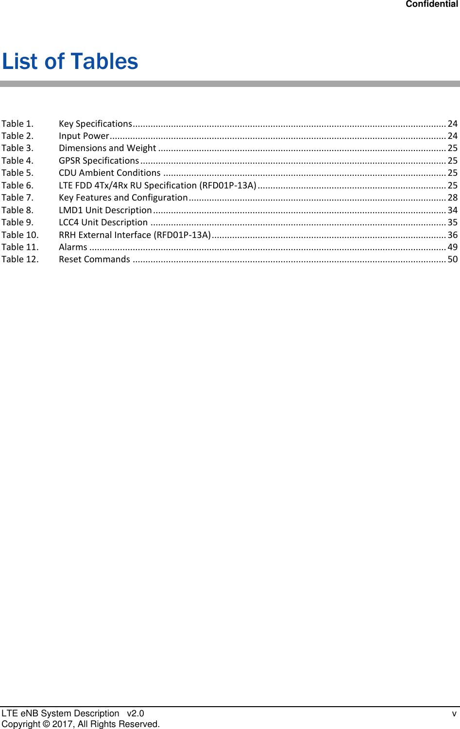
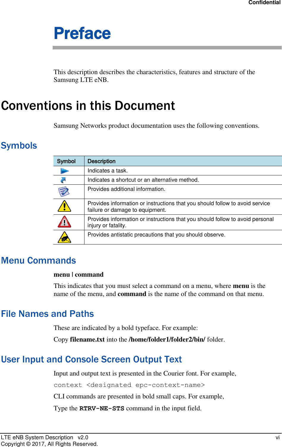
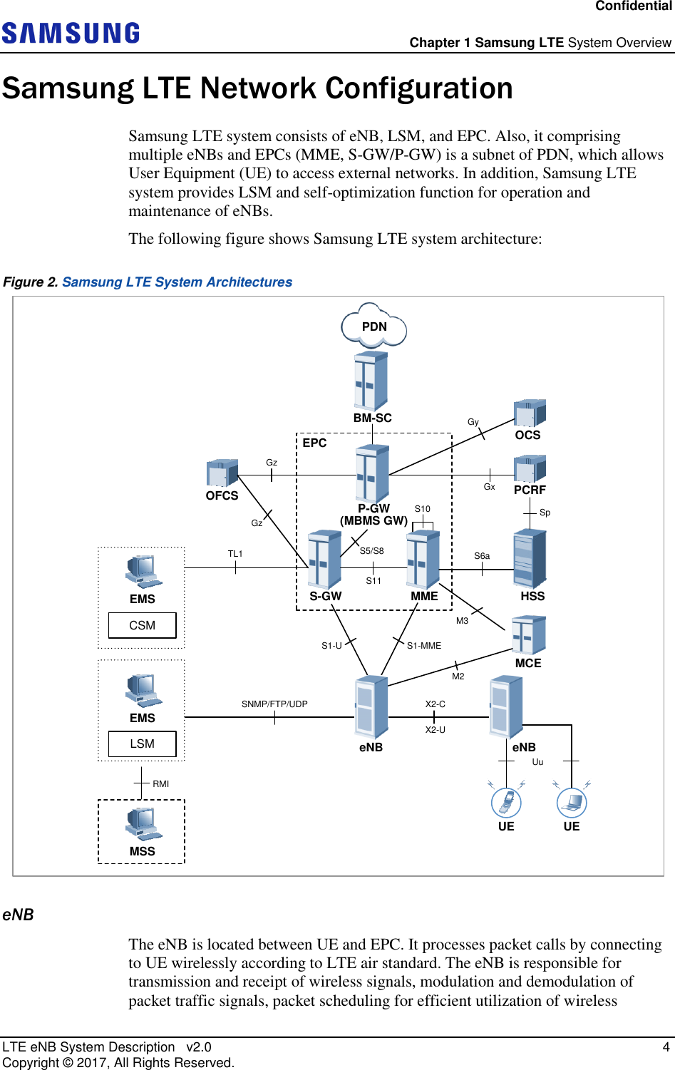
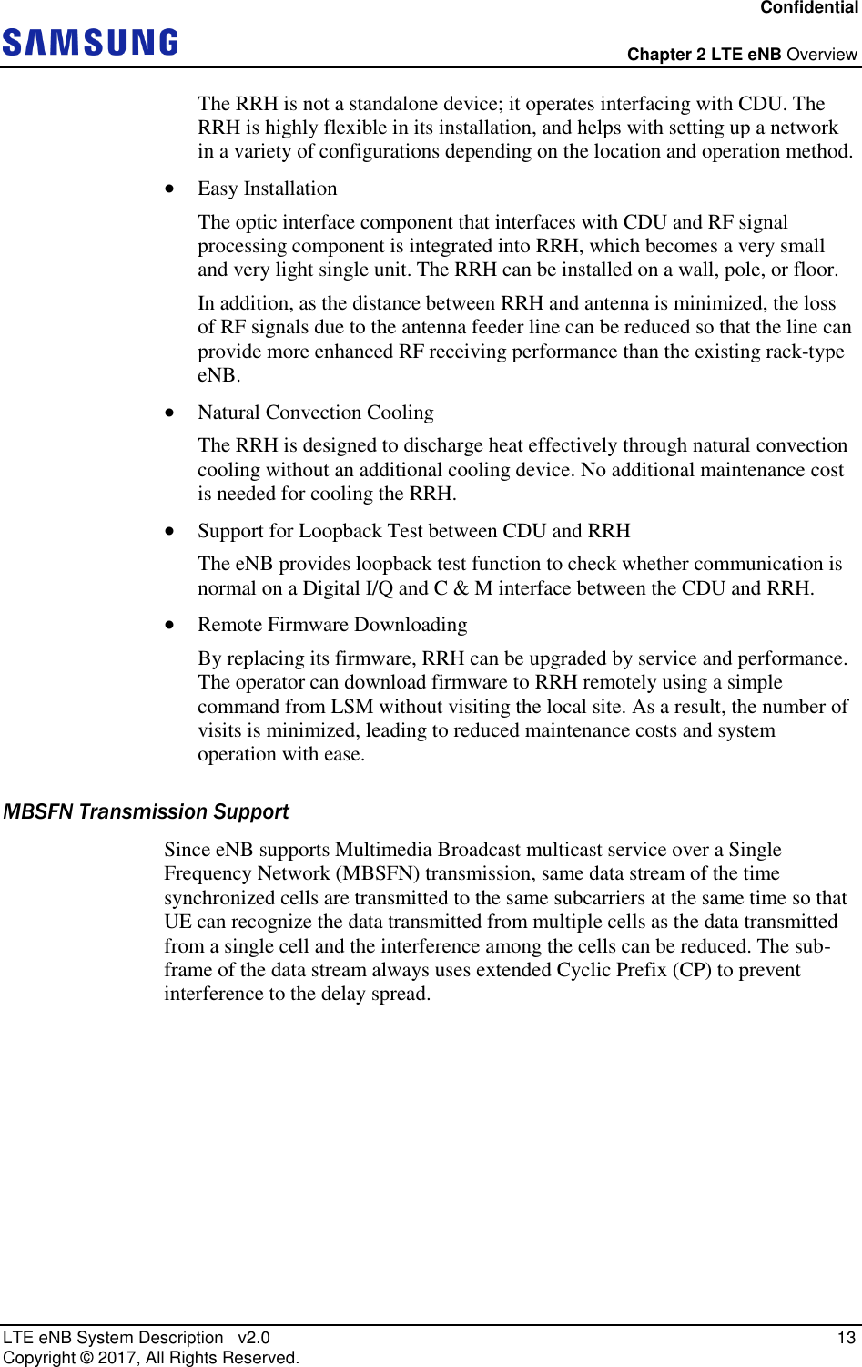
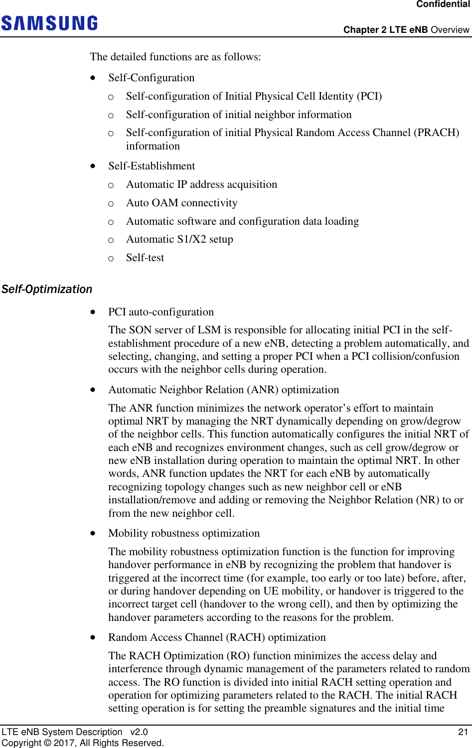
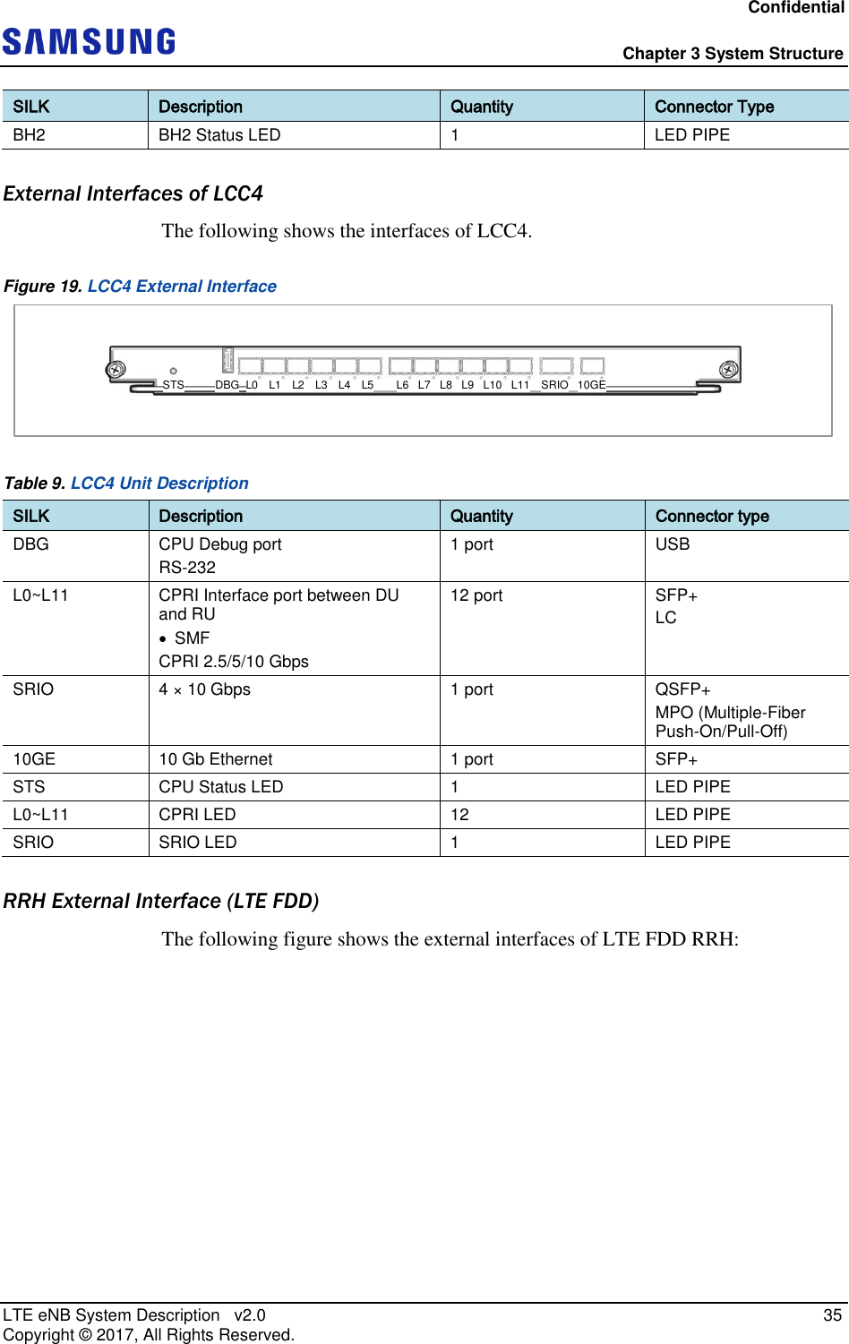
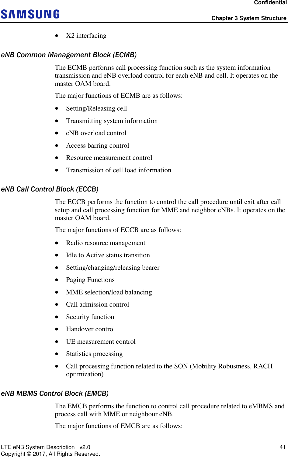
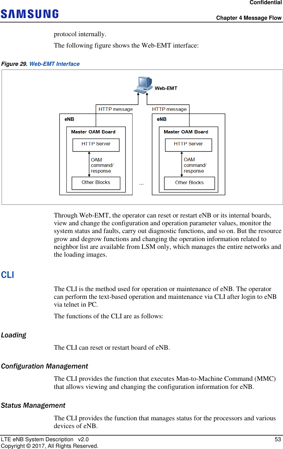
![Confidential Chapter 3 System Structure LTE eNB System Description v2.0 36 Copyright © 2017, All Rights Reserved. Figure 20. RFD01P-13A External Interface ANT1ANT2 ANT3ANT4RET UDA L0 L1SYS OPT ANT RETDC_PWR Table 10. RRH External Interface (RFD01P-13A) I/O Name Interface Connector Type Comments Antenna Port RF [OFDMA/SC-FDMA] 4.3-10 (Plus) female x 4 - DU/RU interface Optic [CPRI 4.2] defaults speeds 9.8Gbps SFP (inner) Push-pull type (outer) Duplex, single mode, 2 ports, 20km RET AISG 2.2 IEC 60130-9 Ed 3.0 Circular 8 pin - TMA AISG 2.2 - TMA is connected through RF ports by bias-T. UDA Open/Close (4 alarms) RJ45 (inner) Push-pull type (outer) - DC power -48V DC 40A 2 pin Push-pull type - LED Status LED - SYS, OPT, ANT, RET](https://usermanual.wiki/Samsung-Electronics-Co/RFD01P-13A.User-Manual-1-Description/User-Guide-3423644-Page-45.png)