Samsung Electronics Co RFD01P-13A RRU (RFD01P) Base Station User Manual 1 Description
Samsung Electronics Co Ltd RRU (RFD01P) Base Station 1 Description
Contents
- 1. User Manual-1 Description
- 2. User Manual-2 Installation
User Manual-1 Description

Radio Access Network
LTE eNB
System Description
Describes an overview of the Samsung system, working, and all major
functionalities.
Document Version 2.0
April 2017
Document Number: 2600-00KGZQGA2

© 2017 SAMSUNG Electronics Co., Ltd.
All Rights Reserved. The contents of this document/presentation contain proprietary information that
must be kept confidential. No part of this document shall be photocopied, reproduced, stored in a
retrieval system, or transmitted, in any form or by any means whether, electronic, mechanical, or
otherwise without the prior written permission of SAMSUNG Electronics Co., Ltd.
No warranty of accuracy is given concerning the contents of the information contained in this
publication. To the extent permitted by law no liability (including liability to any person by reason of
negligence) will be accepted by SAMSUNG Electronics Co., Ltd., its subsidiaries or employees for
any direct or indirect loss or damage caused by omissions from or inaccuracies in this document.
SAMSUNG Electronics Co., Ltd. reserves the right to change details in this publication without notice.
SNMTC-v3-0312
This manual should be read and used as a guideline for properly installing and/or operating the
product. Owing to product variations across the range, any illustrations and photographs used in
this manual may not be a wholly accurate depiction of the actual products you are using.
This manual may be changed for system improvement, standardization and other technical
reasons without prior notice.
Samsung Networks documentation is available at http://www.samsungdocs.com

Confidential
LTE eNB System Description v2.0 iii
Copyright © 2017, All Rights Reserved.
Contents
Preface vi
Conventions in this Document ........................................................................................................ vi
New and Changed Information ...................................................................................................... vii
Revision History .............................................................................................................................. vii
Organization of This Document ..................................................................................................... viii
Personal and Product Safety ........................................................................................................... ix
Chapter 1 Samsung LTE System Overview 1
Introduction to Samsung LTE System ............................................................................................... 1
Samsung LTE Network Configuration ............................................................................................... 4
Protocol Stack between NEs ............................................................................................................ 7
Chapter 2 LTE eNB Overview 12
Introduction to System .................................................................................................................. 12
Main Functions ............................................................................................................................... 14
Physical Layer Processing .......................................................................................................... 14
Call Processing Function ............................................................................................................ 18
IP Processing .............................................................................................................................. 20
SON Function ............................................................................................................................. 20
Easy Operation and Maintenance ............................................................................................. 22
Specifications ................................................................................................................................. 24
Chapter 3 System Structure 27
Hardware Structure ........................................................................................................................ 27
CDU ............................................................................................................................................ 27
RRH (LTE FDD, 700 MHz) ........................................................................................................... 30
Power Supply ............................................................................................................................. 32
Cooling Structure ....................................................................................................................... 33
External Interface ...................................................................................................................... 34
Software Structure ......................................................................................................................... 37
Basic Software Structure ............................................................................................................ 37
CPS Block .................................................................................................................................... 40
OAM Blocks ................................................................................................................................ 44
Chapter 4 Message Flow 48
Data Traffic Flow ............................................................................................................................ 48
Network Sync Flow ......................................................................................................................... 49
Alarm Signal Flow ........................................................................................................................... 49
Loading Flow .................................................................................................................................. 51
Operation and Maintenance Message Flow .................................................................................. 52
Web-EMT ................................................................................................................................... 52
CLI .............................................................................................................................................. 53
Appendix Acronyms 55

Confidential
LTE eNB System Description v2.0 iv
Copyright © 2017, All Rights Reserved.
List of Figures
Figure 1. Functional Distinctions of E-UTRAN and EPC ................................................................................... 2
Figure 2. Samsung LTE System Architectures ................................................................................................. 4
Figure 3. Protocol Stack between UE and eNB ............................................................................................... 7
Figure 4. Protocol Stack between eNB and S-GW User Plane......................................................................... 8
Figure 5. Protocol Stack between eNB and MME Control Plane .................................................................... 8
Figure 6. Inter-eNB User Plane Protocol Stack ................................................................................................ 9
Figure 7. Inter-eNB Control Plane Protocol Stack ........................................................................................... 9
Figure 8. Interface Protocol Stack between eNB and LSM ........................................................................... 10
Figure 9. Protocol Stack between eNB and MCE Server ............................................................................... 10
Figure 10. Protocol Stack between MCE Server and MME ............................................................................. 11
Figure 11. Protocol Stack between MCE Server and LSM ............................................................................... 11
Figure 12. Internal Configuration of eNB ........................................................................................................ 27
Figure 13. CDU Configuration (CDU) ............................................................................................................... 28
Figure 14. RRH Configuration (RFD01P-13A) .................................................................................................. 31
Figure 15. RET Interface .................................................................................................................................. 32
Figure 16. Power Supply Configuration .......................................................................................................... 33
Figure 17. Cooling Structure of CDU ............................................................................................................... 34
Figure 18. LMD1 External Interface ................................................................................................................ 34
Figure 19. LCC4 External Interface .................................................................................................................. 35
Figure 20. RFD01P-13A External Interface ...................................................................................................... 36
Figure 21. eNB Software Structure ................................................................................................................. 37
Figure 22. CPS Structure.................................................................................................................................. 40
Figure 23. OAM Structure ............................................................................................................................... 44
Figure 24. Data Traffic Flow ............................................................................................................................ 48
Figure 25. Network Synchronization Flow ...................................................................................................... 49
Figure 26. Alarm Flow ..................................................................................................................................... 50
Figure 27. Loading Signal Flow ........................................................................................................................ 51
Figure 28. Operation and Maintenance Signal Flow ....................................................................................... 52
Figure 29. Web-EMT Interface ........................................................................................................................ 53

Confidential
LTE eNB System Description v2.0 v
Copyright © 2017, All Rights Reserved.
List of Tables
Table 1. Key Specifications ........................................................................................................................... 24
Table 2. Input Power .................................................................................................................................... 24
Table 3. Dimensions and Weight ................................................................................................................. 25
Table 4. GPSR Specifications ........................................................................................................................ 25
Table 5. CDU Ambient Conditions ............................................................................................................... 25
Table 6. LTE FDD 4Tx/4Rx RU Specification (RFD01P-13A) .......................................................................... 25
Table 7. Key Features and Configuration ..................................................................................................... 28
Table 8. LMD1 Unit Description ................................................................................................................... 34
Table 9. LCC4 Unit Description .................................................................................................................... 35
Table 10. RRH External Interface (RFD01P-13A) ............................................................................................ 36
Table 11. Alarms ............................................................................................................................................ 49
Table 12. Reset Commands ........................................................................................................................... 50
Confidential
LTE eNB System Description v2.0 vi
Copyright © 2017, All Rights Reserved.
Preface
This description describes the characteristics, features and structure of the
Samsung LTE eNB.
Conventions in this Document
Samsung Networks product documentation uses the following conventions.
Symbols
Symbol
Description
Indicates a task.
Indicates a shortcut or an alternative method.
Provides additional information.
Provides information or instructions that you should follow to avoid service
failure or damage to equipment.
Provides information or instructions that you should follow to avoid personal
injury or fatality.
Provides antistatic precautions that you should observe.
Menu Commands
menu | command
This indicates that you must select a command on a menu, where menu is the
name of the menu, and command is the name of the command on that menu.
File Names and Paths
These are indicated by a bold typeface. For example:
Copy filename.txt into the /home/folder1/folder2/bin/ folder.
User Input and Console Screen Output Text
Input and output text is presented in the Courier font. For example,
context <designated epc-context-name>
CLI commands are presented in bold small caps. For example,
Type the RTRV-NE-STS command in the input field.

Confidential
Preface
LTE eNB System Description v2.0 vii
Copyright © 2017, All Rights Reserved.
New and Changed Information
This section describes information that has been added/changed since the previous
publication of this manual.
Technical contents changes.
Revision History
The following table lists all versions of this document.
Document Number
Product/Software
Version
Document
Version
Publication Date
Remarks
2600-00KGZQGA2
LTE eNB
1.0
April 2017
First Version
2600-00KGZQGA2
LTE eNB
2.0
April 2017
-

Confidential
Preface
LTE eNB System Description v2.0 viii
Copyright © 2017, All Rights Reserved.
Organization of This Document
Section
Title
Description
Chapter 1
Samsung LTE
System Overview
Introduction to Samsung LTE System
Samsung LTE Network Configuration
Intersystem Interface
Chapter 2
LTE eNB Overview
Introduction to system
Main functions
Specifications
Chapter 3
System Structure
Hardware structure
Software structure
Chapter 4
Message Flow
Data Traffic Flow
Network Sync Flow
Alarm Signal Flow
Loading Flow
Operation and Maintenance Message Flow
Appendix
Acronyms
This appendix lists acronyms used in this document.

Confidential
Preface
LTE eNB System Description v2.0 ix
Copyright © 2017, All Rights Reserved.
Personal and Product Safety
Proposition 65 (US Only)
State of California Proposition 65 Warning (US only)
WARNING: This product contains chemicals known to the State of California to
cause cancer and birth defects or other reproductive harm.
California USA Only
This Perchlorate warning applies only to primary CR (Manganese Dioxide)
Lithium coin cell batteries in the product sold or distributed ONLY in California
USA.
Perchlorate Material-special handling may apply. See www.dtsc.ca.gov/hazardous
waste/perchlorate.

Confidential
LTE eNB System Description v2.0 1
Copyright © 2017, All Rights Reserved.
Chapter 1 Samsung LTE
System Overview
Introduction to Samsung LTE System
Samsung LTE system supports 3GPP LTE (hereinafter, LTE) based services.
The LTE is a next generation wireless network system which solves the
disadvantages of existing 3GPP mobile systems allows high-speed data service at
low cost regardless of time and place.
Samsung LTE system supports Orthogonal Frequency Division Multiple Access
(OFDMA) for downlink, Single Carrier (SC) Frequency Division Multiple Access
(FDMA) for uplink, and scalable bandwidths for various spectrum allocation and
provides high-speed data service. It also provides high-performance hardware for
improved system performance and capacity and supports various functions and
services.
Samsung LTE system is based on the Rel-8 and Rel-9 standards of LTE 3rd
Generation Partnership Project (3GPP).
Samsung LTE system consists of evolved UTRAN Node B (eNB), Evolved Packet
Core (EPC) and LTE System Manager (LSM).
The eNB exists between EPC and User Equipment (UE). It establishes wireless
connections with UE and processes packet calls according to LTE air interface
standard. The eNB manages UE in connected mode at the Access Stratum (AS)
level. The EPC is the system, which is located between eNB and Packet Data
Network (PDN) to perform various control functions. The EPC consists of
Mobility Management Entity (MME), Serving Gateway (S-GW), and PDN
Gateway (P-GW). The MME manages UE in idle mode at the Non-Access Stratum
(NAS) level. Also, S-GW and P-GW manages user data at the NAS level and
interworks with other networks.
The LSM provides man-machine interface; manages the software, configuration,
performance, and failures. Also, it acts as a Self-Organizing Network (SON)
server.
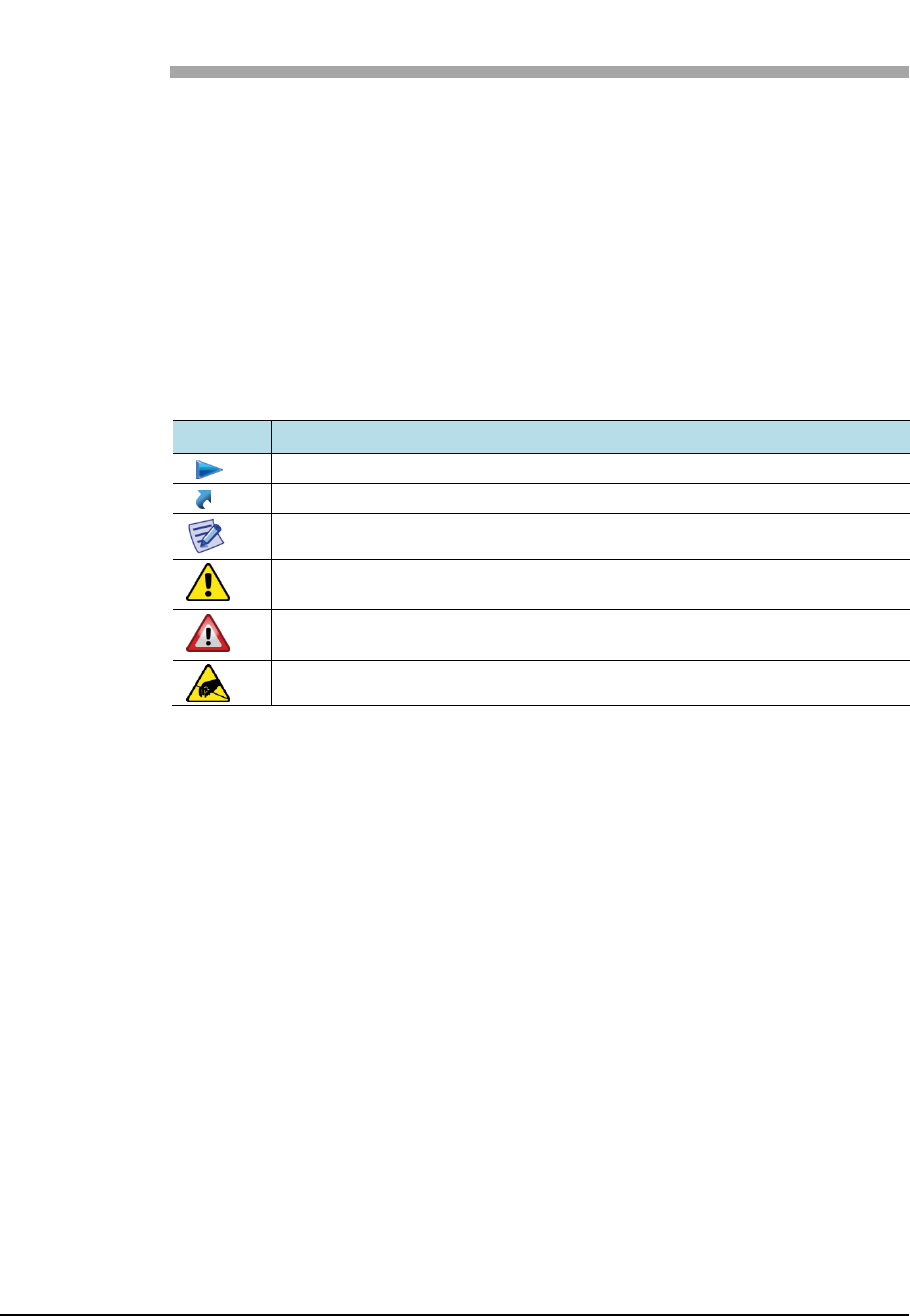
The figure below shows the functional distinctions between eNB of E-UTRAN,
MME, S-GW, and P-GW according to the 3GPP standard. The eNB has a layer
structure and EPC has no layer.
Confidential
Chapter 1 Samsung LTE System Overview
LTE eNB System Description v2.0 2
Copyright © 2017, All Rights Reserved.
Figure 1. Functional Distinctions of E-UTRAN and EPC
eNB
The eNB is a logical network component of Evolved UTRAN (E-UTRAN), which
is located on access side in LTE system.
The eNBs can be interconnected with each other by X2 interface. The eNBs are
connected by S1 interface to Evolved Packet Core (EPC).
The wireless protocol layer of eNB is divided into layer 2 and layer 3. The layer 2
is subdivided into Media Access Control (MAC) layer, Radio Link Control (RLC)
layer, and PDCP layer, each of which performs independent functions. Also,
layer3 has Radio Resource Control (RRC) layer.
The MAC layer distributes air resources to each bearer according to its priority.
Also, it performs multiplexing function and HARQ function for the data, which is
received from the multiple upper logical channels.
The RLC layer performs the following functions:
Segments and reassembles the data, which is received from PDCP layer under
the size specified by MAC layer
Requests retransmission to recover if data transmission fails in the lower layer
(ARQ)
Reorders the data recovered by performing HARQ in MAC layer (re-ordering)
The PDCP layer performs the following functions:
Header compression and decompression
Encrypts/decrypts user plane and control plane data

Confidential
Chapter 1 Samsung LTE System Overview
LTE eNB System Description v2.0 3
Copyright © 2017, All Rights Reserved.
Protects and verifies the integrity of control plane data
Transmits data including sequence number related function
Removes data and redundant data based on a timer
The RRC layer performs mobility management within the wireless access network,
maintaining and control of Radio Bearer (RB), RRC connection management, and
system information transmission, and so on.
MME
The MME interworks with E-UTRAN (eNB) to process the Stream Control
Transmission Protocol (SCTP)-based S1 Application Protocol (S1-AP) signalling
messages for controlling call connections between MME and eNB. Also, MME
process the SCTP-based NAS signalling messages for controlling mobility
connection and call connection between UE and EPC.
The MME is responsible for collecting/modifying the user information and
authenticating the user by interworking with HSS. It is also responsible for
requesting the allocation/release/change of the bearer path for data routing and
retransmission with GTP-C protocol by interworking with S-GW.
The MME interworks with 2G and 3G systems, Mobile Switching Center (MSC),
and Serving GPRS Support Node (SGSN) for providing mobility and Handover
(HO), Circuit Service (CS) fallback, and Short Message Service (SMS).
The MME is responsible for inter-eNB mobility, idle mode UE reachability,
Tracking Area (TA) list management, choosing P-GW/S-GW, authentication, and
bearer management.
The MME supports mobility during inter-eNB handover and inter-MME handover.
It also supports SGSN selection function upon handover to 2G or 3G 3GPP
network.
S-GW
The S-GW acts as the mobility anchor during inter-eNB handover and inter-3GPP
handover, and routes and forwards user data packets. The S-GW allows the
operator to apply application-specific charging policies to UE, PDN or QCI and
manages the packet transmission layers for uplink/downlink data.
The S-GW also supports GPRS Tunnelling Protocol (GTP) and Proxy Mobile IP
(PMIP) by interworking with MME, P-GW, and SGSN.
PDN Gateway (P-GW)
The P-GW is responsible for charging and bearer policy according to the policy
and manages charging and transmission rate according to the service level by
interworking with PCRF. The P-GW also performs packet filtering for each user,
IP address allocation for each UE, and downlink data packet transmission layer
management.
Confidential
Chapter 1 Samsung LTE System Overview
LTE eNB System Description v2.0 4
Copyright © 2017, All Rights Reserved.
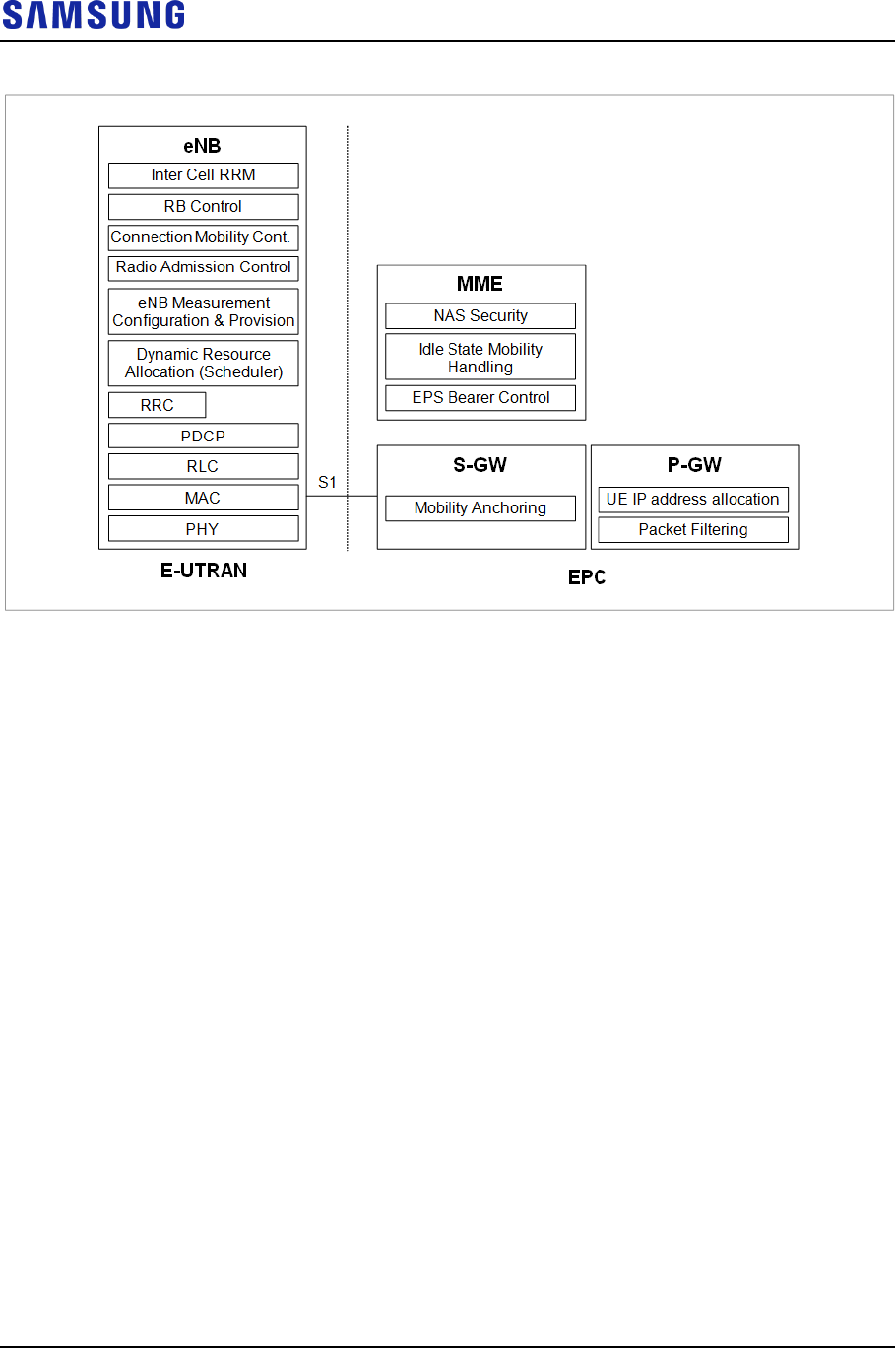
Samsung LTE Network Configuration
Samsung LTE system consists of eNB, LSM, and EPC. Also, it comprising
multiple eNBs and EPCs (MME, S-GW/P-GW) is a subnet of PDN, which allows
User Equipment (UE) to access external networks. In addition, Samsung LTE
system provides LSM and self-optimization function for operation and
maintenance of eNBs.
The following figure shows Samsung LTE system architecture:
Figure 2. Samsung LTE System Architectures
EPC
S1-MME
Gz
Gz
S5/S8
S11
S10
Gy
Gx
Sp
S6a
HSS
PCRF
OCS
OFCS
CSM
EMS S-GW MME
P-GW
(MBMS GW)
S1-U
TL1
LSM
EMS
SNMP/FTP/UDP
RMI
eNB eNB
X2-U
X2-C
Uu
UE UE
MSS
MCE
M2
M3
PDN
BM-SC
eNB
The eNB is located between UE and EPC. It processes packet calls by connecting
to UE wirelessly according to LTE air standard. The eNB is responsible for
transmission and receipt of wireless signals, modulation and demodulation of
packet traffic signals, packet scheduling for efficient utilization of wireless

Confidential
Chapter 1 Samsung LTE System Overview
LTE eNB System Description v2.0 5
Copyright © 2017, All Rights Reserved.
resources, Hybrid Automatic Repeat Request (HARQ)/ARQ processing, Packet
Data Convergence Protocol (PDCP) for packet header compression, and wireless
resources control.
In addition, eNB performs handover by interworking with EPC.
EPC
The EPC is a system, which is located between eNB and PDN. The
subcomponents of EPC are MME, S-GW and P-GW, Multimedia
Broadcast/Multicast Service Gateway (MBMS GW).
MME: Processes control messages using the NAS signaling protocol with eNB
and performs control plane functions such as UE mobility management,
tracking area list management, and bearer and session management.
S-GW: Acts as the anchor for user plane between 2G/3G access system, LTE
system, and manages and changes the packet transmission layer for
downlink/uplink data.
P-GW: Allocates an IP address to UE, acts as the anchor for mobility between
LTE and non-3GPP access systems, and manages/changes charging and
transmission rate according to the service level.
LTE System Manager (LSM)
The LSM provides user interface for the operator to operate and maintain eNB.
The LSM is responsible for software management, configuration management,
performance management and fault management, and acts as a SON server.
Core System Manager (CSM)
The CSM provides user interface for the operator to operate and maintain MME,
S-GW, and P-GW.
Master SON Server (MSS)
The MSS interoperates with local SON server as its higher node, making
optimized interoperation possible for the multi-LSM. The MSS can work with
Operating Support System (OSS) of the service provider who can decide whether
to link them.
Home Subscriber Server (HSS)
The HSS is a database management system that stores and manages the parameters
and location information for all registered mobile subscribers. The HSS manages
key data such as the mobile subscriber’s access capability, basic services and
supplementary services, and provides a routing function to the subscribed receivers.
Policy and Charging Rule Function (PCRF)
The PCRF server creates policy rules to dynamically apply the QoS and charging

Confidential
Chapter 1 Samsung LTE System Overview
LTE eNB System Description v2.0 6
Copyright © 2017, All Rights Reserved.
policies differentiated by service flow, or creates the policy rules that can be
applied commonly to multiple service flows. The P-GW includes Policy and
Charging Enforcement Function (PCEF), which allows application of policy rules
received from PCRF to each service flow.
Online Charging System (OCS)
The OCS collects online charging information by interfacing with S-GW and P-
GW.
When a subscriber for whom online charging information is required makes a call,
P-GW transmits and receives the subscriber’s charging information by
interworking with OCS.
Offline Charging System (OFCS)
The OFCS collects offline charging information by interfacing with S-GW and P-
GW.
The OFCS uses GTP’ (Gz) or Diameter (Rf) interface to interface with S-GW and
P-GW.
Multi-cell/Multicast Coordination Entity (MCE)
The MCE is located between MME and eNB. It is responsible for session control
signaling, admission control, radio resource allocations for eMBMS. M2 and M3
interface is used to interwork with eNB and MME.
Confidential
Chapter 1 Samsung LTE System Overview
LTE eNB System Description v2.0 7
Copyright © 2017, All Rights Reserved.
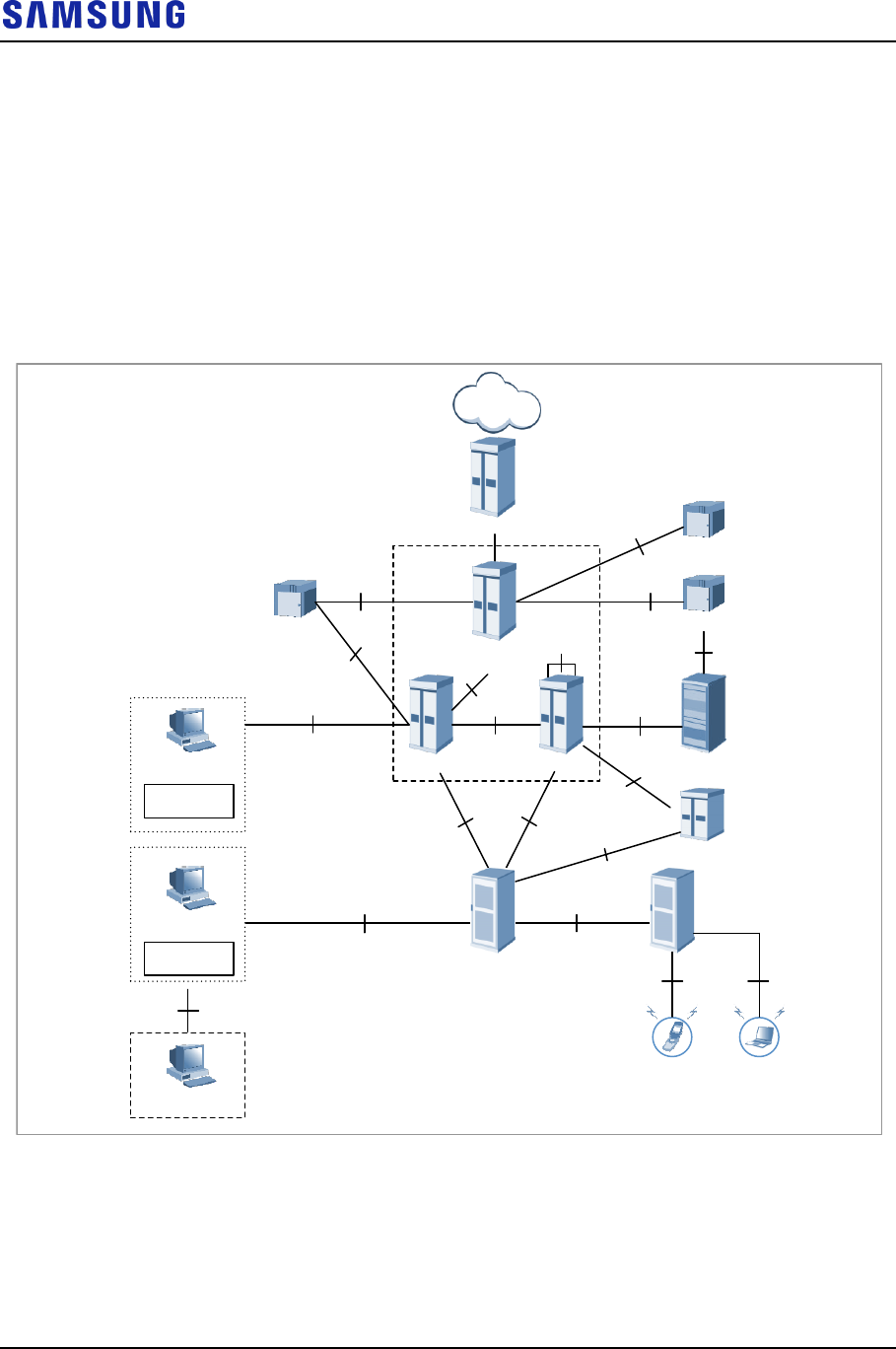
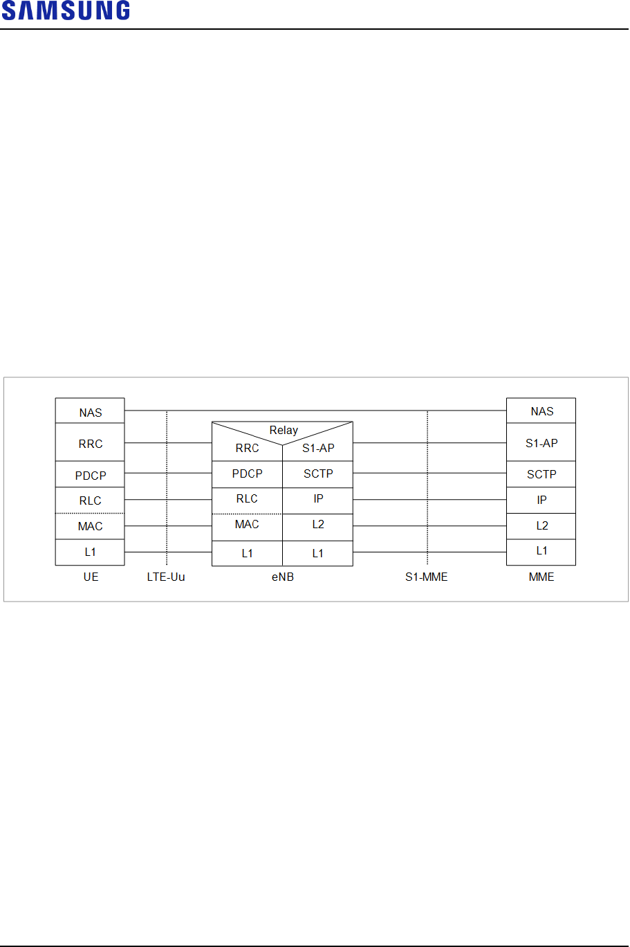
Protocol Stack between NEs
The inter-NE protocol stack of the eNB is as follows:
Protocol Stack between UE and eNB
The user plane protocol layer consists of PDCP, RLC, MAC, and PHY layers.
The user plane is responsible for transmission of user data (e.g. IP packets)
received from the upper layer. In user plane, all protocols are terminated in eNB.
The control plane protocol layer is composed of the NAS layer, RRC layer, PDCP
layer, RLC layer, MAC layer, and PHY layer. The NAS layer is located on the
upper wireless protocol. It performs UE authentication between UE and MME,
security control, and paging and mobility management of UE in LTE IDLE mode.
In control plane, all protocols except for the NAS signal are terminated in eNB.
Figure 3. Protocol Stack between UE and eNB
Protocol Stack between eNB and EPC
The eNB and EPC are connected physically through FE and GE method, and the
connection specification should satisfy LTE S1-U and S1-MME interface.
In user plane, GTP-User (GTP-U) is used as the upper layer of the IP layer; and in
Control plane, SCTP is used as the upper layer of the IP layer.
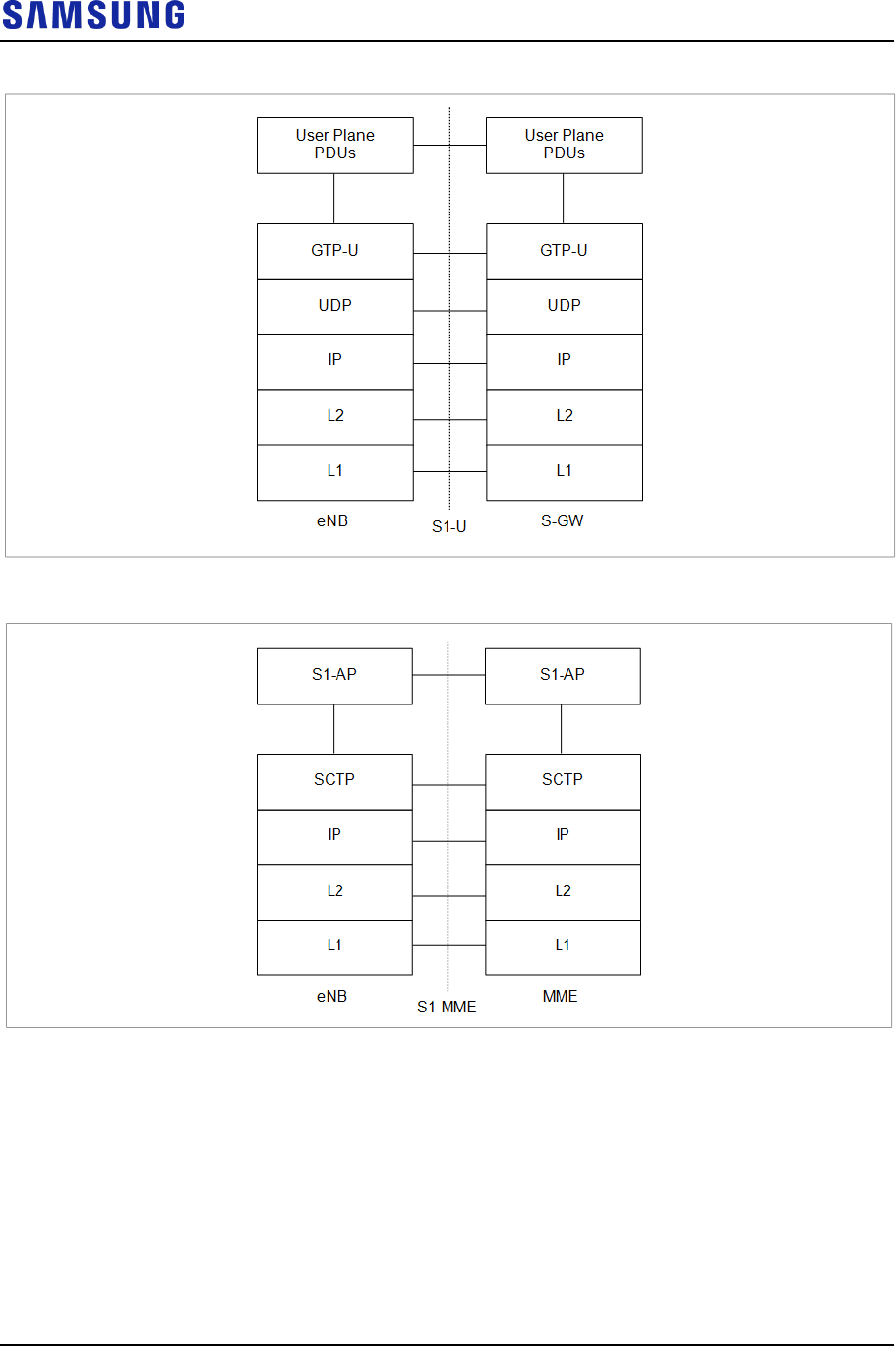
The figure below shows the user plane protocol stack between eNB and S-GW:
Confidential
Chapter 1 Samsung LTE System Overview
LTE eNB System Description v2.0 8
Copyright © 2017, All Rights Reserved.
Figure 4. Protocol Stack between eNB and S-GW User Plane
Figure 5. Protocol Stack between eNB and MME Control Plane
Inter-eNB Protocol Stack
The two eNBs are connected physically through FE and GE method, and the
connection specification should satisfy LTE X2 interface.
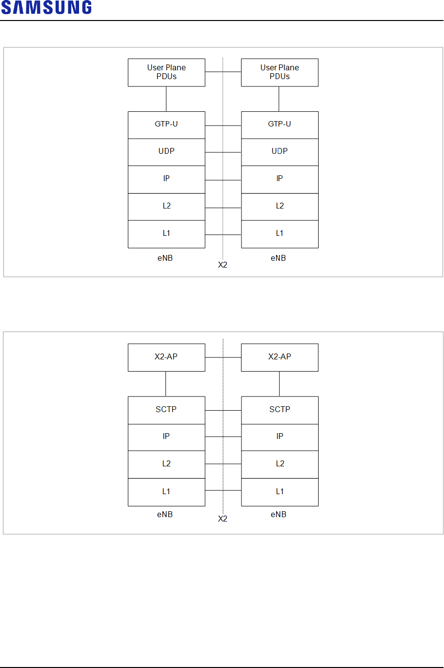
The following figure shows the inter-eNB user plane protocol stack:
Confidential
Chapter 1 Samsung LTE System Overview
LTE eNB System Description v2.0 9
Copyright © 2017, All Rights Reserved.
Figure 6. Inter-eNB User Plane Protocol Stack
The following figure shows the control plane protocol stack:
Figure 7. Inter-eNB Control Plane Protocol Stack
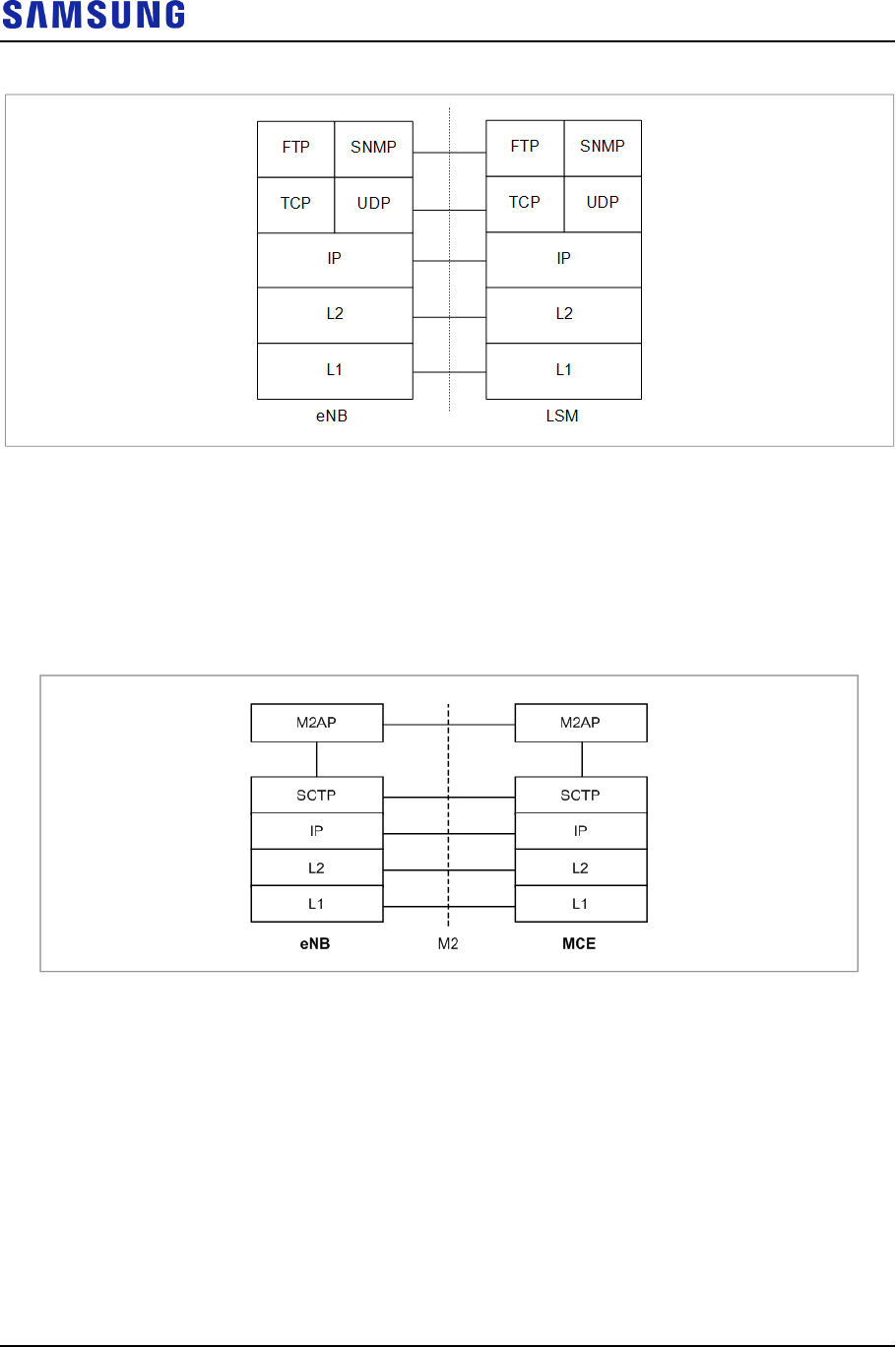
Protocol Stack between eNB and LSM
The FE and GE are used for the physical connection between eNB and LSM, and
connection specifications must satisfy FTP/SNMP interface.
The following figure shows the user plane protocol stack between eNB and LSM:
Confidential
Chapter 1 Samsung LTE System Overview
LTE eNB System Description v2.0 10
Copyright © 2017, All Rights Reserved.
Figure 8. Interface Protocol Stack between eNB and LSM
Protocol Stack between eNB and MCE Server
The eNB must provide the interface for the interoperation with the MCE server.
GE is used for physical connection between the eNB and MCE server. The
connection specification must satisfy the STCP interface.
Figure 9. Protocol Stack between eNB and MCE Server
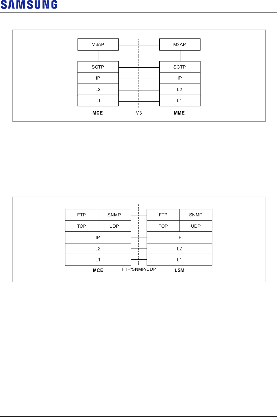
Protocol Stack between MCE Server and MME
GE is used for physical connection between the MME and MCE server. The
connection specification must satisfy the STCP interface. The protocol stack
between the MCE server and MME is as follows:
Confidential
Chapter 1 Samsung LTE System Overview
LTE eNB System Description v2.0 11
Copyright © 2017, All Rights Reserved.
Figure 10. Protocol Stack between MCE Server and MME
Protocol Stack between MCE Server and LSM
GE is used for physical connection between the LSM and MCE server. The
connection specification must satisfy the FTP/SNMP/UDP interface. The
following diagram shows the interface protocol stack between the MCE server and
LSM.
Figure 11. Protocol Stack between MCE Server and LSM

Confidential
LTE eNB System Description v2.0 12
Copyright © 2017, All Rights Reserved.
Chapter 2 LTE eNB Overview
Introduction to System
In LTE system, eNB is located between UE and EPC. The eNB provides mobile
communications services to subscribers according to LTE air interface standard.
The eNB transmits/receives radio signals to/from UE and processes the
modulation and demodulation of packet traffic signals. The eNB is also
responsible for packet scheduling and radio bandwidth allocation and performs
handover via interface with EPC.
The eNB consists of Digital Unit (DU) and Radio Unit (RU).
The CDU is a digital unit (19-inch shelf) and can be mounted into indoor or
outdoor 19-inch commercial rack.
The RRH is a RF integration module consisting of a transceiver, power amplifier,
and filter. It transmits and receives traffic, clock information, and alarm/control
messages to and from the CDU. The RRH has 4Tx/4Rx, 2Tx/4Rx or 2Tx/2Rx
configurations supporting optic CPRI and can be installed on outdoor wall or pole.
The main features of eNB are as follows:
High Compatibility and Interoperability
The eNB complies with the specifications released based on the 3GPP standard.
So, it has high compatibility and interoperability.
High-Performance Modular Structure
The eNB has high-performance with the use of high-performance processors.
It is easy to upgrade hardware and software because of its modular structure.
Support for Advanced RF and Antenna Solutions
The eNB adopts the power amplifier to support wideband operation bandwidth and
Multiple Input Multiple Output (MIMO).
Separation of CDU and RRH
The eNB consists of CDU and RRH separately for easy installation and flexible
network configuration. In case of connection between CDU and RRH, data traffic
signals and OAM information are transmitted/received through the Digital I/Q and
C & M interface based on the Common Public Radio Interface (CPRI). Physically,
optic cables are used.
The CDU and RRH are supplied DC -48 V DC power from a rectifier respectively.
Flexible Network Configuration

Confidential
Chapter 2 LTE eNB Overview
LTE eNB System Description v2.0 13
Copyright © 2017, All Rights Reserved.
The RRH is not a standalone device; it operates interfacing with CDU. The
RRH is highly flexible in its installation, and helps with setting up a network
in a variety of configurations depending on the location and operation method.
Easy Installation
The optic interface component that interfaces with CDU and RF signal
processing component is integrated into RRH, which becomes a very small
and very light single unit. The RRH can be installed on a wall, pole, or floor.
In addition, as the distance between RRH and antenna is minimized, the loss
of RF signals due to the antenna feeder line can be reduced so that the line can
provide more enhanced RF receiving performance than the existing rack-type
eNB.
Natural Convection Cooling
The RRH is designed to discharge heat effectively through natural convection
cooling without an additional cooling device. No additional maintenance cost
is needed for cooling the RRH.
Support for Loopback Test between CDU and RRH
The eNB provides loopback test function to check whether communication is
normal on a Digital I/Q and C & M interface between the CDU and RRH.
Remote Firmware Downloading
By replacing its firmware, RRH can be upgraded by service and performance.
The operator can download firmware to RRH remotely using a simple
command from LSM without visiting the local site. As a result, the number of
visits is minimized, leading to reduced maintenance costs and system
operation with ease.
MBSFN Transmission Support
Since eNB supports Multimedia Broadcast multicast service over a Single
Frequency Network (MBSFN) transmission, same data stream of the time
synchronized cells are transmitted to the same subcarriers at the same time so that
UE can recognize the data transmitted from multiple cells as the data transmitted
from a single cell and the interference among the cells can be reduced. The sub-
frame of the data stream always uses extended Cyclic Prefix (CP) to prevent
interference to the delay spread.

Confidential
Chapter 2 LTE eNB Overview
LTE eNB System Description v2.0 14
Copyright © 2017, All Rights Reserved.
Main Functions
The main functions of LTE eNB are as follows:
Physical Layer Processing
Call Processing Function
IP Processing
SON Function
Interfacing with Auxiliary Devices
Easy Operation and Maintenance
In case of availability and provision schedule of the features and functions
described in the system manual, refer to separate documentations.
Physical Layer Processing
The eNB transmits/receives data through the radio channel between EPC and UE.
To do so, eNB provides the following functions:
OFDMA/SC-FDMA Scheme
Downlink Reference Signal Creation and Transmission
Downlink Synchronization Signal Creation and Transmission
MBSFN Reference Signal Creation and Transmission
Channel Encoding/Decoding
Modulation/Demodulation
Resource Allocation and Scheduling
Link Adaptation
HARQ
Power Control
ICIC
MIMO
OFDMA/SC-FDMA Scheme
The eNB performs downlink OFDMA/uplink SC-FDMA channel processing that
supports LTE standard physical layer. The downlink OFDMA scheme allows the
system to transmit data to multiple users simultaneously using the subcarrier
allocated to each user. Depending on the channel status and transmission rate
requested by the user, downlink OFDM can allocate one or more subcarriers to a
specific subscriber to transmit data.

Confidential
Chapter 2 LTE eNB Overview
LTE eNB System Description v2.0 15
Copyright © 2017, All Rights Reserved.
In addition, when all sub-carriers are divided for multiple users, eNB can select
and assign to each subscriber a sub-carrier with the most appropriate features using
the OFDMA scheme, thus to distribute resources efficiently and increase data
throughput.
In case of uplink SC-FDMA, which is similar to OFDMA modulation and
demodulation, a Discrete Fourier Transform (DFT) is applied to each subscriber in
the modulation at the transmitting side. An inverse Discrete Fourier Transform
(IDFT) is applied for minimizing the Peak to Average Power Ratio (PAPR) at the
transmitting side, which allows continuous allocation of frequency resources
available for individual subscribers. As a result, eNB can reduce the power
consumption of the UE.
Downlink Reference Signal Creation and Transmission
The UE must estimate downlink channel to perform the coherent demodulation on
the physical channel in LTE system. The LTE uses OFDM/OFDMA-based
methods for transmitting and therefore the channel can be estimated by inserting
the reference symbols from the receiving terminal to the grid of each time and
frequency. These reference symbols are called downlink reference signals, and
there are 2 types of reference signal defined in LTE downlink.
Cell-specific reference signal: The cell-specific reference signal is transmitted
to every subframe across the entire bandwidth of the downlink cell. It is
mainly used for channel estimation, MIMO rank calculation, MIMO precoding
matrix selection and signal strength measurement for handover.
UE-specific Reference Signal: The UE-specific reference signal is used for
channel estimation for coherent demodulation of DL-SCH transmission where
the beamforming method is used. UE-specific means that the reference signal
is used for channel estimation of a specified UE only. Therefore, the UE-
specific reference signal is used in the resource block allocated for DL-SCH
only, which is transmitted to the specified UE.
Downlink Synchronization Signal Creation and Transmission
The synchronization signal is used for initial synchronization when UE starts to
communicate with eNB.
There are two types of synchronization signals:
Primary Synchronization Signal (PSS)
Secondary Synchronization Signal (SSS)
The UE can obtain cell identity through the synchronization signal. It can obtain
other information about cell through the broadcast channel. Since synchronization
signals and broadcast channels are transmitted in 1.08 MHz range, which is right
in the middle of cell’s channel bandwidth, UE can obtain the basic cell information
such as cell ID regardless of the transmission bandwidth of eNB.
MBSFN Reference Signal Creation and Transmission
In the enhanced/evolved Multimedia Broadcast Multicast Services (eMBMS)

Confidential
Chapter 2 LTE eNB Overview
LTE eNB System Description v2.0 16
Copyright © 2017, All Rights Reserved.
system, MBSFN reference signal of MBSFN sub-frame in addition to the cell-
specific reference signal and UE-specific reference signal used by the existing
unicast. These both reference signals are used to estimate the downlink physical
channel by inserting the reference symbols that can be recognized by the reception
layer MBSFN reference signal.
The MBSFN reference signal is provided in 15 MHz subcarrier spacing in case of
extended CP to antenna port number 4.
Channel Encoding/Decoding
The eNB is responsible for channel encoding/decoding to correct the channel
errors that occurred on a wireless channel. In LTE, the turbo coding and the 1/3
tail-biting convolutional coding are used. Turbo coding is mainly used for
transmission of large data packets on downlink and uplink, while convolutional
coding is used for control information transmission and broadcast channel for
downlink and uplink.
Modulation/Demodulation
In case of data received over downlink from the upper layer, eNB processes it
through baseband of the physical layer and transmits it via a wireless channel.
At this time, to transmit a baseband signal as far as it can go via the wireless
channel, the system modulates and transmits it on a specific high frequency
bandwidth.
In case of data received over uplink from UE through a wireless channel, eNB
demodulates and changes it to baseband signal to perform decoding.
Resource Allocation and Scheduling
To support multiple accesses, eNB uses OFDMA for downlink and SC-FDMA for
uplink. By allocating the 2-dimensional resources of time and frequency to
multiple UEs without overlay, both methods enable eNB to communicate with
multiple UEs simultaneously.
When eNB operates in MU-MIMO mode, the same resource also may be used for
multiple UEs simultaneously. Such allocation of cell resources to multiple UEs is
called scheduling, and each cell has its own scheduler for this function.
The LTE scheduler of eNB allocates resources to maximize the overall throughput
of the cell by considering channel environment of each UE, the data transmission
volume required, and other QoS elements. In addition, to reduce interferences with
other cells, eNB can share information with the schedulers of other cells over the
X2 interface.
Link Adaptation
The wireless channel environment can become faster or slower, better or worse
depending on various factors. The system is capable of increasing the transmission
rate or maximizing the total cell throughput in response to the changes in the
channel environment, and this is called link adaptation.

Confidential
Chapter 2 LTE eNB Overview
LTE eNB System Description v2.0 17
Copyright © 2017, All Rights Reserved.
In particular, Modulation Coding Scheme (MCS) is used for changing the
modulation method and channel coding rate according to the channel status. If
channel environment is good, MCS increases the number of transmission bits per
symbol using a high-order modulation, such as 256 QAM. If channel environment
is bad, it uses a low-order modulation, such as QPSK and a low coding rate to
minimize channel errors.
In addition, in the environment where MIMO mode can be used, eNB operates in
MIMO mode to increase the peak data rate of subscribers and can greatly increase
the cell throughput.
If the channel information obtained is incorrect or modulation method of higher
order or higher coding rate than the given channel environment is used, errors may
occur.
In such cases, errors can be corrected by HARQ function.
H-ARQ
The H-ARQ is a retransmission method in the physical layer, which uses the stop-
and-wait protocol. The eNB provides H-ARQ function to retransmit or combine
frames in the physical layer so that the effects of wireless channel environment
changes or interference signal level changes can be minimized, which results in
throughput improvement.
The LTE uses Incremental Redundancy (IR)-based H-ARQ method and regards
the Chase Combining (CC) method as a special case of the IR method.
The eNB uses asynchronous method for downlink and synchronous method for
uplink.
Power Control
When transmitting a specific data rate, too high power level may result in
unnecessary interferences and too low power level may result in an increased error
rate, causing retransmission or delay. Unlike in other schemes such as CDMA, the
power control is relatively less important in LTE. Nevertheless, adequate power
control can improve performance of LTE system.
In LTE uplink, SC-FDMA is used so that there are no near-far problems that occur
in CDMA. However, the high level of interference from nearby cells can degrade
the uplink performance.
Therefore, UE should use adequate power levels for data transmission in order not
to interfere with nearby cells. Likewise, the power level for each UE could be
controlled for reducing the inter-cell interference level.
In LTE downlink, eNB can reduce inter-cell interference by transmitting data at
adequate power levels according to the location of UE and MCS, which results in
improvement of the entire cell throughput.
Inter-Cell Interference Coordination (ICIC)
Since UEs within a cell in LTE use orthogonal resources with no interference
between UEs, there is no intra-cell interference.

Confidential
Chapter 2 LTE eNB Overview
LTE eNB System Description v2.0 18
Copyright © 2017, All Rights Reserved.
However, if different UEs in neighbor cells use the same resource, interference
may occur. This occurs more seriously between UEs located on the cell edge,
resulting in serious degradation at cell edge.
A scheme used to relieve such inter-cell interference problem on the cell edge is
ICIC.
The ICIC allows interference signals to be transmitted to other cells in the cell
edge area in as small an amount as possible by allocating a basically different
resource to each UE that belongs to a different cell and by carrying out power
control according to UE’s location in the cell.
The eNBs exchange scheduling information with each another via X2 interface for
preventing interferences by resource conflicts at cell edges. If the interference of a
neighbor cell is too strong, the system informs other system to control strength of
the interference system.
The ICIC scheme is used to improve the overall cell performance.
MIMO
The LTE eNB supports 2Tx/2Rx, 2Tx/4Rx or 4Tx/4Rx MIMO by default using
multiple antennas.
To support multiple antennas, the baseband module of the eNB channel card
processes MIMO, and each path of the RF is processed separately. The LTE eNB
provides high-performance data services by supporting several types of MIMO.
Call Processing Function
Cell Information Transmission
In a serving cell, eNB periodically transmits a Master Information Block (MIB)
and System Information Blocks (SIBs), which are system information, to allow UE
that receives them to perform proper call processing.
Call Control and Air Resource Assignment
The eNB allows UE to be connected to or disconnected from the network.
When UE is connected to or released from the network, eNB transmits and
receives the signaling messages required for call processing to and from UE via
the Uu interface, and to and from EPC via the S1 interface.
When UE connects to the network, eNB performs call control and resource
allocation required for service. When UE is disconnected from the network, eNB
collects and releases the allocated resources.
In case of more information on the handover procedure, refer to ‘Message Flow’
section below.

Confidential
Chapter 2 LTE eNB Overview
LTE eNB System Description v2.0 19
Copyright © 2017, All Rights Reserved.
Admission Control (AC)
The eNB provides capacity-based admission control and QoS-based admission
control for a bearer setup requested from EPC so that the system is not overloaded.
Capacity-based admission control
There is a threshold for the maximum number of connected UEs (new
calls/handover calls) and bearers that can be allowed in eNB. Call admission is
determined depending on whether the connected UEs and bearers exceed the
thresholds.
QoS-based admission control
The eNB determines whether to admit a call depending on the estimated PRB
usage of the newly requested bearer, the PRB usage status of the bearers in
service, and the maximum acceptance limit of the PRB (per bearer type, QCI,
and UL/DL).
RLC ARQ
The eNB performs ARQ function for the RLC Acknowledged Mode (AM) only.
When receiving and transmitting the packet data, RLC transmits SDU by dividing
it into units of RLC PDU at the transmitting side. Also, the packet is retransmitted
(forwarded) according to ARQ feedback information received from the receiving
side for increased reliability of the data communication.
QoS Support
The eNB receives QoS Class Identifier (QCI) in which QoS characteristics of the
bearer are defined and GBR, MBR, and the Aggregated Maximum Bit Rate (UE-
AMBR) from the EPC. It provides QoS for the wireless section between UE and
eNB and the backhaul section between eNB and S-GW.
Through air interface, it performs retransmission to satisfy the rate control
according to GBR/MBR/UE-AMBR values, priority of bearer defined in QCI, and
scheduling considering packet delay budget, and the Packet Loss Error Rate
(PLER).
Through backhaul interface, it performs QCI-based packet classification, QCI to
DSCP mapping, and marking for the QoS. It provides queuing depending on
mapping results, and each queue transmits packets to the EPC according to a strict
priority, and so on.
In Element Management System (EMS), besides to the QCI predefined in the
specifications, operator-specific QCI, and QCI-to-DSCP mapping can be set.
SYNC Handler Function
The eNB provides Synchronization (SYNC) protocol function to the backhaul
section between eNB and MBMS-GW for each Temporary Mobile Group ID
(TMGI) of the MBMS bearer from MME.

Confidential
Chapter 2 LTE eNB Overview
LTE eNB System Description v2.0 20
Copyright © 2017, All Rights Reserved.
IP Processing
IP QoS
The eNB can provide the backhaul QoS when communicating with EPC by
supporting the Differentiated Services (DiffServ).
The eNB supports 8 classes of DiffServ and mapping QoS between services
classes of the user traffic received from MS and DiffServ classes. In addition, eNB
supports mapping the services classes based on Differentiated Services Code
Points (DSCP) to the 802.3 Ethernet MAC service classes.
IP Routing
Since eNB provides multiple Ethernet interfaces, it stores in the routing table
information on which Ethernet interface of IP packets will be routed to. The
routing table of eNB is configured by the operator. The method for configuring
routing table is similar to the standard router configuration method.
The eNB supports static routing settings, but does not support dynamic routing
protocols such as Open Shortest Path First (OSPF) or Border Gateway Protocol
(BGP).
IP Multicast Routing
The eNB provides multiple Ethernet interfaces, and it stores information on which
Ethernet interface IP packets will be routed to the routing table.
The routing table of eNB is configured by the operator in the similar way to the
router standard configuration. IP multicast is based on PIM and IGMPv2 SSM.
Ethernet/VLAN Interface
The eNB provides Ethernet interfaces and supports the static link grouping, Virtual
Local Area Network (VLAN), and Ethernet CoS functions that comply with IEEE
802.3ad for Ethernet interfaces. The MAC bridge function defined in IEEE 802.1D
is not supported.
The eNB allows multiple VLAN IDs to be set for an Ethernet interface. To support
Ethernet CoS, it maps DSCP value of IP header to the CoS value of the Ethernet
header for Tx packets.
SON Function
The SON function supports the self-configuration, self-establishment and self-
optimization function.
Self-Configuration and Self-Establishment
Self-configuration and self-establishment enable automatic setup of radio
parameters and automatic configuration from system ‘power-on’ to ‘in-service’,
which minimizes the effort in installing the system.

Confidential
Chapter 2 LTE eNB Overview
LTE eNB System Description v2.0 21
Copyright © 2017, All Rights Reserved.
The detailed functions are as follows:
Self-Configuration
o Self-configuration of Initial Physical Cell Identity (PCI)
o Self-configuration of initial neighbor information
o Self-configuration of initial Physical Random Access Channel (PRACH)
information
Self-Establishment
o Automatic IP address acquisition
o Auto OAM connectivity
o Automatic software and configuration data loading
o Automatic S1/X2 setup
o Self-test
Self-Optimization
PCI auto-configuration
The SON server of LSM is responsible for allocating initial PCI in the self-
establishment procedure of a new eNB, detecting a problem automatically, and
selecting, changing, and setting a proper PCI when a PCI collision/confusion
occurs with the neighbor cells during operation.
Automatic Neighbor Relation (ANR) optimization
The ANR function minimizes the network operator’s effort to maintain
optimal NRT by managing the NRT dynamically depending on grow/degrow
of the neighbor cells. This function automatically configures the initial NRT of
each eNB and recognizes environment changes, such as cell grow/degrow or
new eNB installation during operation to maintain the optimal NRT. In other
words, ANR function updates the NRT for each eNB by automatically
recognizing topology changes such as new neighbor cell or eNB
installation/remove and adding or removing the Neighbor Relation (NR) to or
from the new neighbor cell.
Mobility robustness optimization
The mobility robustness optimization function is the function for improving
handover performance in eNB by recognizing the problem that handover is
triggered at the incorrect time (for example, too early or too late) before, after,
or during handover depending on UE mobility, or handover is triggered to the
incorrect target cell (handover to the wrong cell), and then by optimizing the
handover parameters according to the reasons for the problem.
Random Access Channel (RACH) optimization
The RACH Optimization (RO) function minimizes the access delay and
interference through dynamic management of the parameters related to random
access. The RO function is divided into initial RACH setting operation and
operation for optimizing parameters related to the RACH. The initial RACH
setting operation is for setting the preamble signatures and the initial time

Confidential
Chapter 2 LTE eNB Overview
LTE eNB System Description v2.0 22
Copyright © 2017, All Rights Reserved.
resource considering the neighbor cells. The operation for optimizing
parameters related to the RACH is for estimating the RACH resources, such as
time resource and subscriber transmission power required for random access,
that change depending on time, and for optimizing the related parameters.
Mobility Load Balancing (MLB)
The MLB function monitors the cell’s load. If the load status satisfies the
MLB execution condition specified by the operator, this function moves a part
of the traffic to a neighbor cell through network-initiated HO. The MLB
execution condition is divided into load equalization condition among multiple
carriers, and the overload condition of a cell.
Easy Operation and Maintenance
The eNB interworks with management systems such as LSM, Web-EMT, and CLI.
It provides the following maintenance functions:
System initialization and restart
System configuration management
Management of fault/status/diagnosis for system resources and services
Management of statistics on system resources and various performance data
Security management for system access and operation
Graphics and Text Based Console Interfaces
The LSM manages all eNBs in the network using Database Management System
(DBMS). The eNB also interworks with console terminal to allow the operator to
connect directly to the Network Element (NE), rather than through LSM, and
perform the operations and maintenance.
The operator can use the graphics-based console interface (Web-EMT, Web-based
Element Maintenance Terminal) or the text-based Command Line Interface (CLI)
according to user convenience and work purposes. Also, they can access the
console interfaces without additional software. In case of Web-EMT, the operator
can log in to the system using Internet Explorer. In case of CLI, the operator can
log in to the system using telnet or Secure Shell (SSH) in the command window.
The operator can perform the management of configuration and operational
information, management of fault and status, and monitoring of statistics and so on.
To grow/degrow resources or configure a neighbor list that contains relation of
multiple NEs, the operator needs to use the LSM.
Operator Authentication Function
The eNB provides the authentication and privilege management functions for the
system operators.
The operator accesses eNB using their account and password via the CLI.
At this time, eNB allows the operator an operation privilege by the operator’s level.

Confidential
Chapter 2 LTE eNB Overview
LTE eNB System Description v2.0 23
Copyright © 2017, All Rights Reserved.
The eNB also logs the access successes and failures for CLI, login history, and so
on.
Highly-Secured Maintenance
The eNB supports the Simple Network Management Protocol (SNMP) and SSH
File Transfer Protocol (SFTP) for security during communications with LSM, and
Hypertext Transfer Protocol over SSL (HTTPs) and Secure Shell (SSH) during
communications with the console terminal.
Online Software Upgrade
When a software package is upgraded, EPC can upgrade the existing package
while it is still running.
The package upgrade is done by downloading a new package activating of the
new package. The download and activation of a new package is performed using
the Download and Activation menu of LSM GUI.
When upgrading the package, the service stops temporarily at the ‘change to the
new package’ step because the existing process needs to be stopped so that the
new process can start. Since the operating system does not need to be restarted, the
service can be resumed within several minutes. After upgrading the software, the
eNB updates the package, which is stored in the internal non-volatile storage.
Call Trace
The eNB supports the call trace function for a specific UE.
The operator can enable trace for a specific UE through MME. The trace execution
results such as signaling messages are transmitted to LSM.
OAM Traffic Throttling
The eNB provides the operator with the function for suppressing OAM-related
traffic that can occur in the system using the operator command. At this time, the
target OAM-related traffic includes the fault trap messages for alarm reporting and
the statistics files generated periodically.
In case of fault trap messages, the operator can suppress generation of alarms for
the whole system or some fault traps using the alarm inhibition command,
consequently allowing the operator to control the amount of alarm traffic that is
generated. In case of statistics files, the operator can control the amount of
statistics files by disabling the statistics collection function for each statistics group
using the statistics collection configuration command.

Confidential
Chapter 2 LTE eNB Overview
LTE eNB System Description v2.0 24
Copyright © 2017, All Rights Reserved.
Specifications
Key Specifications
The key specifications of eNB are as follows:
Table 1. Key Specifications
Category
Specification
Technology
3GPP Rel. 13
Duplex type
FDD
Operating Frequency
DL: 746 to 756 MHz
UL: 777 to 787 MHz
Channel Bandwidth
10 MHz 4Tx/4Rx, 2Tx/4Rx or 2Tx/2Rx per RRH
CDU-RRH Interface
Max. 36 Optic CPRI
Capacity
Max. 12 cells @ 10/20MHz 4Tx/4Rx, 2Tx/4Rx or
2Tx/2Rx
Max. 18,000 RRC connected UEs
Max. 54,000 bearers
*) Per cell
o Max. 600 RRC connected UEs
o Max. 1,800 bearers
Backhaul Links
100/1000 Base-T Copper (RJ-45) 1 Port
1000 Base-X SFP 1 Port
1000 Base-X/10 GBase-SR/LR SFP+ 1 Port
Input Power
-48 V DC
Clock sync
IEEE1588v2, GNSS
Input Power
The following table shows the power specifications for LTE eNB. The LTE eNB
complies with UL60950 safety standard for electrical equipment. If the operator
needs AC power for the system input voltage, it can be supplied using an
additional external rectifier (installed by the provider).
Table 2. Input Power
Category
Specifications
CDU
-48 V DC (-40.5~-57 V DC)
RRH
-48 V DC (-38~-57 V DC)
Dimensions and Weight
The following table shows the dimensions and weight of LTE eNB:

Confidential
Chapter 2 LTE eNB Overview
LTE eNB System Description v2.0 25
Copyright © 2017, All Rights Reserved.
Table 3. Dimensions and Weight
Category
Specifications
Dimensions (W × D × H, mm)
CDU
434 × 385 × 88
RRH
320 × 320 × 151
Weight (kg)
CDU
15 or less (based on full configuration)
RRH
Approx. 17
GPSR Specifications
The following table shows the specifications of LTE eNB’s GPS Receiver (GPSR):
Table 4. GPSR Specifications
Category
Specifications
Received Signal from GPS
GPS L1 Signal
Accuracy/Stability (ppm)
0.05
Ambient Conditions
The following table shows the operating temperature, humidity level and other
ambient conditions and related standard of CDU:
Table 5. CDU Ambient Conditions
Category
Specifications
Temperature Condition (°C) a)
0~50
Humidity Condition a)
5~90 %RH, non-condensing, not to exceed 30 g/㎥
absolute humidity.
Altitude (m)
-60~1,800 (Telcordia GR-63-CORE)
Earthquake
Telcordia Earthquake Risk Zone4 (Telcordia GR-63-
CORE)
Vibration
Vibration in Use
o 5~100 Hz, 0.15 grms (Telcordia GR-63-CORE)
Transportation Vibration
o 5~200 Hz, 0.89 grms (Telcordia GR-63-CORE)
Sound Power Level
Maximum 78 dB at 27°C (Telcordia GR-63-CORE Issue
4, Section 4.6 Acoustic Noise, Sound Power Level)
EMC
FCC Title 47 CFR Part 15
GR-1089-CORE
Safety
UL 60950-1
a) Temperature and humidity are measured at 1.5 m above the floor and at 400 mm away
from the front panel of the equipment.
The following table shows the ambient conditions and related standard of RRH:
Table 6. LTE FDD 4Tx/4Rx RU Specification (RFD01P-13A)
Item
RFD01P-13A

Confidential
Chapter 2 LTE eNB Overview
LTE eNB System Description v2.0 26
Copyright © 2017, All Rights Reserved.
Item
RFD01P-13A
Operating Temperature (°C)
-40~55 (without solar load)
Operating Humidity
5~100 % RH, condensing, not to exceed 30g/㎥
absolute humidity
Altitude (m)
-60~1,800 (Telcordia GR-63-CORE)
Earthquake
Telcordia Earthquake Risk Zone4 (Telcordia GR-63-
CORE)
Vibration
Office Vibration (Section 4.4.4)
Transportation Vibration (Section 4.4.5)
Noise
Fanless (natural convection cooling)
EMC
FCC Title 47 CFR Part 15
Safety
UL 60950-1 2nd Ed.
RF
FCC Title 47 CFR Part 27
Confidential
LTE eNB System Description v2.0 27
Copyright © 2017, All Rights Reserved.
Chapter 3 System Structure
Hardware Structure
The LTE eNB is the system that consists of Cabinet DU (CDU) which is a
common platform DU, and Remote Radio Heads (RRH) which is an RU.
CDU
The CDU is connected to RRH through CPRI, and it can provide up to 4 carrier/3
sector service.
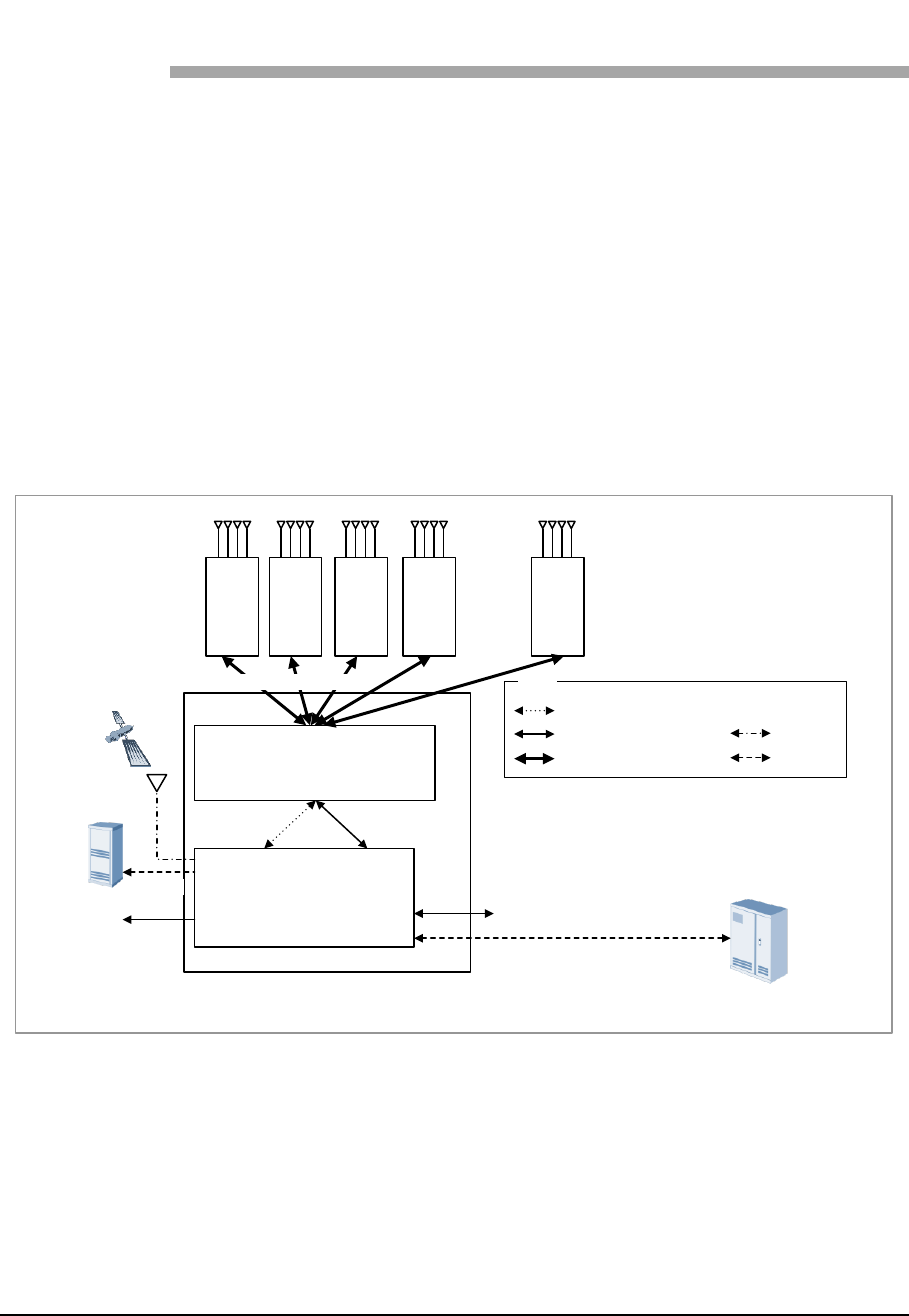
The following figure shows the configuration of LTE eNB:
Figure 12. Internal Configuration of eNB
Index
Data Traffic + Alarm/Control (Ethernet)
Alarm/Control
CPRI Interface (Optic)
Clock
Backhaul
LCC4-B1A
LMD1-J1A
CDU
R
R
H
(0)
R
R
H
(1)
R
R
H
(2)
GPS
EPC
UDE (FE)
9.8 Gbps CPRI Interface
Rectifier
Power (-48 V DC)
UDA (9Rx/2Tx)
FE/GE
R
R
H
(3)
R
R
H
(11)
. . .
Up to three channel card can be mounted in a CDU and LCC4 has a capacity of 1
carrier/3 sector per board by default.
The four slots of CDU are multi-board type slots where LMD1 carries out the
main processor function, network interface function, clock generation and
distribution function, provider-requested alarm processing, and so on. The LCC4-
B1A carries out the modem function. The power module, fan, and air filter are also
installed.
The RRH is an RF integration module consisting of a transceiver, power amplifier,
Confidential
Chapter 3 System Structure
LTE eNB System Description v2.0 28
Copyright © 2017, All Rights Reserved.
and filter. It sends and receives traffic, clock information, and alarm/control
messages to and from LCC4. It has 4Tx/4Rx, 2Tx/4Rx or 2Tx/2Rx configurations
with optic CPRI support.
Each RRH is connected an optic CPRI; up to 12 RRHs can be connected to LCC4.
The CDU is the multi-board type DU in which LMD1 that carries out the main
processor function, network interface function, and clock creation and distribution
function. The LCC4 carries out the modem function are mounted. It consists of the
power module (PDPM), FANM-C4A, and air filter. The CDU is mounted on a 19
inch rack, with fan cooling and EMI available in each unit, and supports a RRH
and optic CPRI interface.
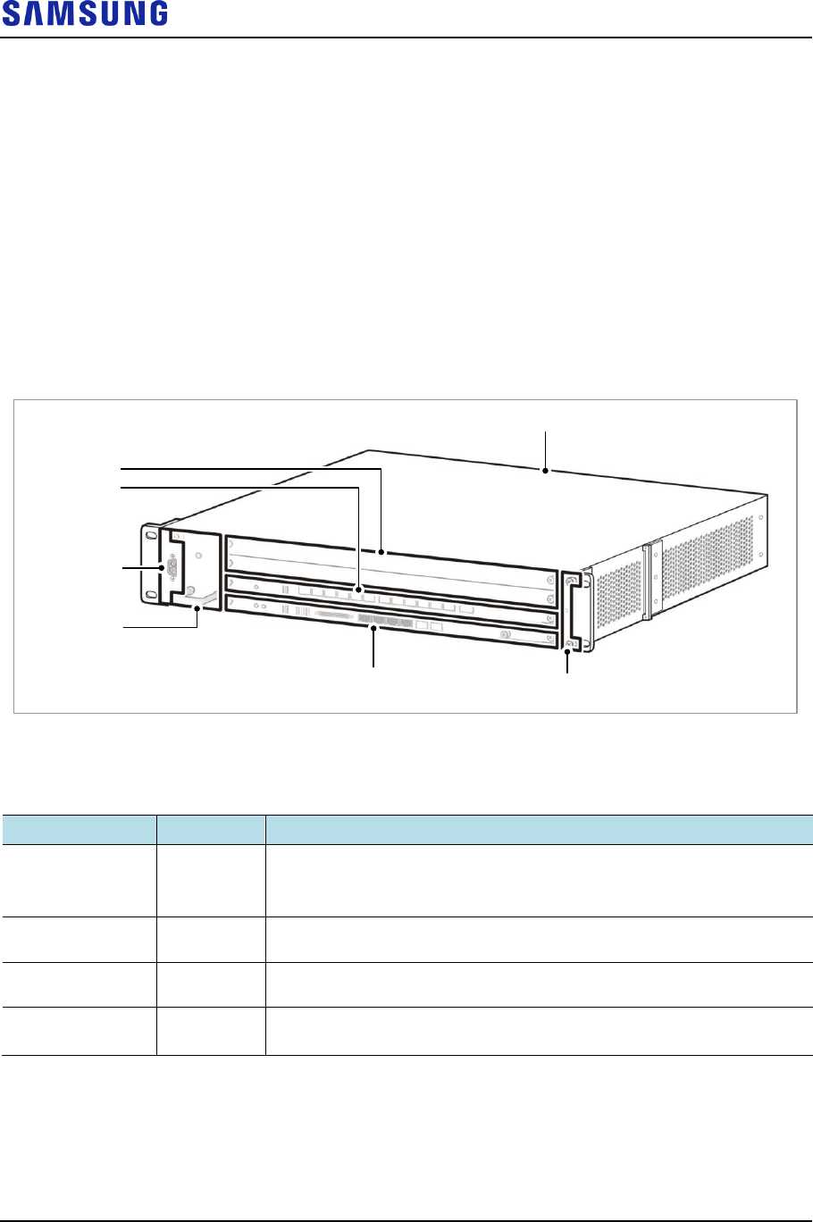
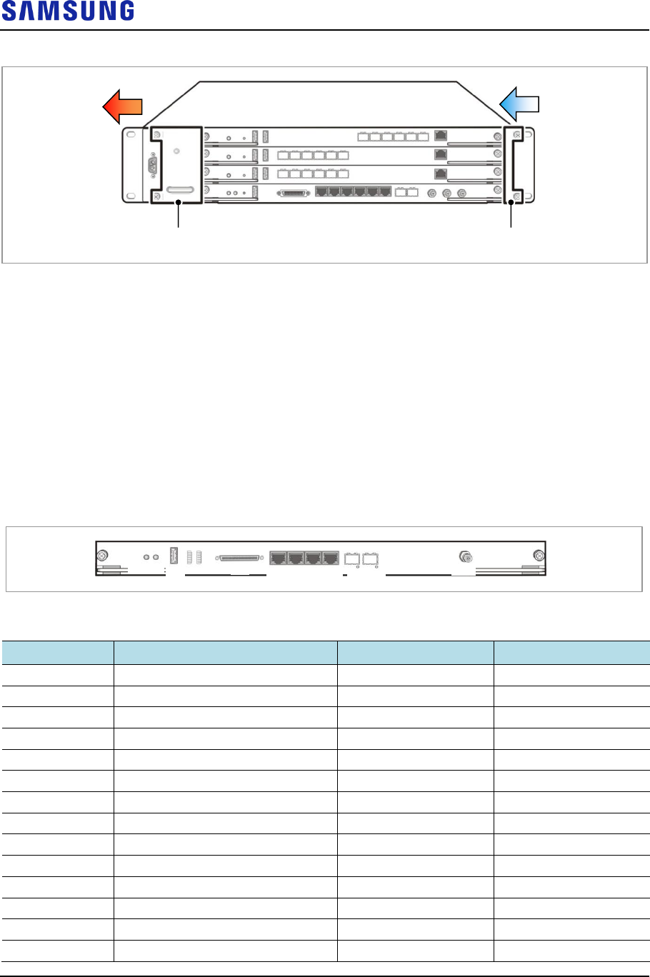
The following figure shows CDU configuration:
Figure 13. CDU Configuration (CDU)
UADB
blank
LCC4-B1A
Power
FANM-C4A
LMD1-J1A Air filter
The following table shows the key features and configurations of each board:
Table 7. Key Features and Configuration
Board
Quantity
Description
UADB
1
Universal platform type A Digital Backplane board assembly
CDU backboard
Routing signals for traffic, control, clocks, power, and so on.
LMD1-J1A
1
Main processing card for clock generation/distribution, network interfacing,
IP processing, system OAM function and UDE/UDA function.
LCC4-B1A
Max. 3
Channel processing card for call processing, resource assignment,
OFDMA/SC-FDMA channel processing, and CPRI interface with RU.
FANM-C4A
1
Fan Module-C4A
CDU cooling fan module
LMD1
The LMD1 provides main processor function, interface with network, interfaces
with external devices, and clock generation and distribution.
Main Processor Feature

Confidential
Chapter 3 System Structure
LTE eNB System Description v2.0 29
Copyright © 2017, All Rights Reserved.
The LMD1, LTE main processor of eNB plays role as the highest layer. It is
responsible for communication path configuration between UE and EPC,
Ethernet Switching functionality for internal eNB, and System OAM. Also, it
manages entire hardware and software status within eNB, allocates/manages
resources, and collect/report the alarm status information to LSM (LTE
System Manager).
Network Interface Feature
The LMD1 is Gigabit Ethernet/Fast Ethernet, and it interfaces with EPC.
Depending on the provided interface, LMD1 can be classified as following
types, and operator can choose the interface to use.
o 100/1000 Base-T Copper (RJ-45) 1 Port
o 1000 Base-X Small Form factor Pluggable (SFP) 1 Port
o 1000 Base-X/10 GBase-SR/LR Small Form factor Pluggable+ (SFP+) 1
Port
External Interface Feature
The LMD1 can provide Ethernet interface for User Defined Ethernet (UDE)
within CDU. Through Fast Ethernet interface of CDU, LMD1 can provide
paths to external alarm information (such as Rectifier alarm/control, battery
monitoring data or UDE/UDA). Then, this alarm information is sent to LSM.
Clock Generation and Distribution
The LMD1's clock module generates 10 MHz, Even, and SFN (System Frame
Number) based on the sync signal which is received from GPS, and distributes
this to the Hardware block of the system. This clock maintains the internal
synchronization of eNB, and used for system operation. Clock module can
forward ‘time data’ and ‘location data’ via TOD Path.
If GPS signal was not received for some reason, clock module provides
holdover feature that can maintain the normal clock for specified time period.
LCC4-B1A
The functions of LCC4 are as follows:
Subscriber channel processing
The LCC4 modulate the packet data, which is received from LMD1 and
transmits it through CPRI to RRH. Reversely, it demodulates the data received
from RRH and converts it to the format defined in LTE physical layer standard
and transmits it to LMD1.
CPRI interface
The LCC4 interfaces with RRH through CPRI. As LCC4 contains a built-in
Electrical to Optic (E/O) conversion device and an Optic to Electrical (O/E)
conversion device, it can transmit and receive ‘Digital I/Q and C & M’ signals
between remote RRHs. The LCC4 can also run loopback tests to check
whether the interface between LCC4 and RRHs is in good condition for proper
communication. If necessary, the operator can run loopback tests using LSM
command.

Confidential
Chapter 3 System Structure
LTE eNB System Description v2.0 30
Copyright © 2017, All Rights Reserved.
10GE interface
The LCC4 provides a 10GE interface to support UL CoMP between DUs.
FANM-C4A
The FANM-C4A is the system’s cooling fan used to maintain the internal CDU
shelf temperature. With this fan, the system can operate normally when the outside
temperature of CDU shelf changes.
RRH (LTE FDD, 700 MHz)
The RRH is installed outdoor by default with a natural cooling convection system.
The RRH, having 4Tx/4Rx, 2Tx/4Rx or 2Tx/2Rx RF chains, is an integrated RF
module consisting of a transceiver, a power amplifier, and a filter in an outdoor
enclosure.
The major functions of the RRH are as follows:
700 MHz (DL: 746 to 756MHz, UL: 777 to 787MHz)
Supports 10 MHz 4Tx/4Rx, 2Tx/4Rx or 2Tx/2Rx per RRH
Supports 10 MHz 1 carrier/1 sector
In case of 4T, 40 W per path (Total 160 W), Max 160 W per carrier
In case of 2T, 60 W per path (Total 120 W), Max 120 W per carrier
Up/Down RF conversion
Performs LNA function
Amplifies the RF signal level
Suppresses spurious waves from the bandwidth
Includes E/O and O/E conversion module for the optical communication with
CDU
Supports Remote Electrical Tilting (RET)

Confidential
Chapter 3 System Structure
LTE eNB System Description v2.0 31
Copyright © 2017, All Rights Reserved.
Figure 14. RRH Configuration (RFD01P-13A)
In downlink path, RRH performs O/E conversion for the baseband signals, which
is received from CDU via the optic CPRI. The converted O/E signals are
converted again into analog signals by the DAC.
The frequency of those analog signals is converted upward through the modulator
and those signals are amplified into high-power RF signals through the power
amplifier.
The amplified signals are transmitted to antenna through the filter part.
In uplink path, RF signals received through the filter of RRH are low-noise
amplified in the Low Noise Amplifier (LNA) and their frequency is then down-
converted through the demodulator. These down-converted frequency signals are
converted to baseband signals through the ADC. The signals converted into
baseband are changed to E/O through CPRI and transmitted to CDU.
The control signals of the RRH are transmitted through the control path in the
CPRI.
To save energy, RRH provides the function to turn ON or OFF the power amplifier
output through to the software command set according to traffic changes.
When adjusting the maximum output after the initial system installation, RRH
adjusts the voltage applied to the main transistor through the software command
set in high/low mode to optimize efficiency of the system.
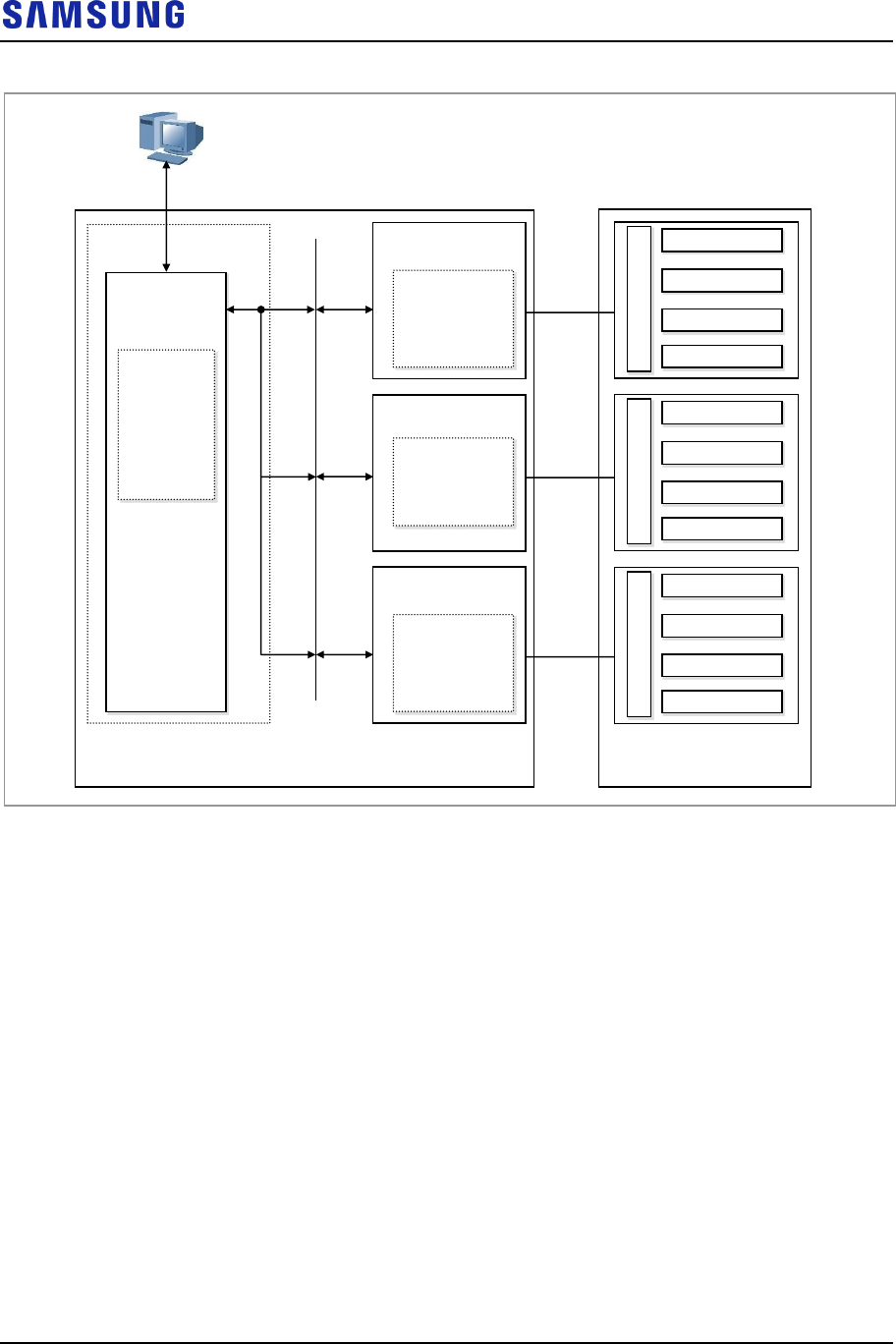
RET
The eNB can support RET function through connection to antenna and RRH,
which satisfies the AISG 2.2 interface.
To provide RET function, eNB transmits/receives the control messages to/from
LSM through the RET controller within LCC4 and CPRI path of CPRI FPGA.
By using this path, LSM can carry out RET function that controls the antenna
tilting angle remotely. In addition, for RET operation, RRH provides power to
every connected antenna.
Confidential
Chapter 3 System Structure
LTE eNB System Description v2.0 32
Copyright © 2017, All Rights Reserved.
Figure 15. RET Interface
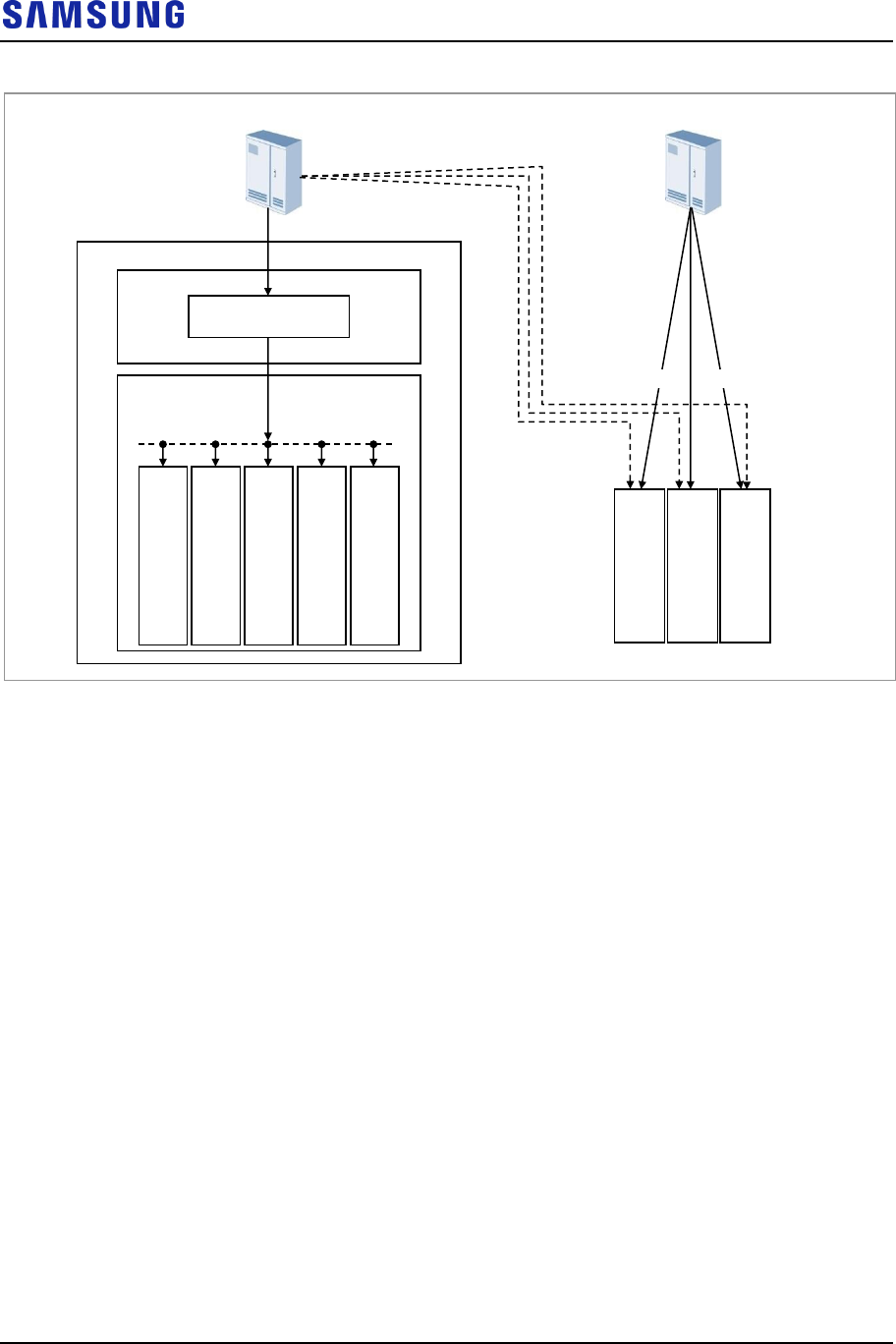
Power Supply
The following figure shows the type of power supply to eNB and connection
points:
CPRI
CDU
LCC4
Power
LSM
(SNMP Manager)
.
.
.
Antenna (AISG interface)
.
.
.
RRH (0)
RET Relay
RRH (1)
RET Relay
RRH (2)
RET Relay
RET
Controller
R
E
T
M
o
t
o
r
R
E
T
M
o
t
o
r
R
E
T
M
o
t
o
r
Antenna
Antenna
Antenna
Antenna
Antenna
Antenna
Antenna
Antenna
Antenna
Antenna
Antenna
Antenna
Confidential
Chapter 3 System Structure
LTE eNB System Description v2.0 33
Copyright © 2017, All Rights Reserved.
Figure 16. Power Supply Configuration
The power for LMD1 and LCC4-B1As in CDU is supplied through the Power
Distribution Panel Module (PDPM) and UADB, a backboard. Each board uses the
power by converting -48 V DC provided into the power needed for each part on
the board.
Cooling Structure
CDU
The CDU maintains inside temperature of the shelf at an appropriate range using a
system cooling fans (FANM-C4), with this fan, the system can operate normally
when the outside temperature of CDU shelf changes.
The following figure shows the heat radiation structure of CDU:
L
M
D
1
L
C
C
4
L
C
C
4
L
C
C
4
F
A
N
M
-
C
4
A
CDU
PDPM
EMI Filter
-48 V DC (-40.5~-57 V DC)
Rectifier
Rectifier
R
R
H
(0)
R
R
H
(1)
R
R
H
(2)
-48 V DC (-38~-57 V DC)
UADB
Confidential
Chapter 3 System Structure
LTE eNB System Description v2.0 34
Copyright © 2017, All Rights Reserved.
Figure 17. Cooling Structure of CDU
RRH
The RRH is designed to discharge heat effectively through natural convection
cooling without an additional cooling device.
External Interface
External Interfaces of LMD1
The following shows the interfaces of LMD1.
Figure 18. LMD1 External Interface
STS CLK DBG UDA BH0 ETH LMT ALM GNSS
BH1 BH2
CLK0 CLK1
Table 8. LMD1 Unit Description
SILK
Description
Quantity
Connector Type
BH0
BH 1G Copper
1 port
RJ-45
BH1
BH 1G Optic
1 port
SFP
BH2
BH 1G/10G Optic
1 port
SFP+
UDA
User Defined Alarm
1 port
CHAMP-68P
ALM
External Equipment Alarm
1 port
RJ-45
DBG
Debugger RS-232
1 port
USB
ETH
UDE 1G Copper
1 port
RJ-45
LMT
Local Maintenance Terminal
1 port
RJ-45
GNSS
GPS L1 interface
1 port
SMA (Female)
CLK0
Digital clock
1 port
Har link-10P
CLK1
Digital clock
1 port
Har link-10P
STS
CPU Status LED
1
LED PIPE
CLK
Clock Status LED
1
LED PIPE
BH1
BH1 Status LED
1
LED PIPE
FANM-C4A
Air Filter

Confidential
Chapter 3 System Structure
LTE eNB System Description v2.0 35
Copyright © 2017, All Rights Reserved.
SILK
Description
Quantity
Connector Type
BH2
BH2 Status LED
1
LED PIPE
External Interfaces of LCC4
The following shows the interfaces of LCC4.
Figure 19. LCC4 External Interface
STS DBG L0 L1 L2 L3 L4 L5 L6 L7 L8 L9 L10 L11 SRIO 10GE
Table 9. LCC4 Unit Description
SILK
Description
Quantity
Connector type
DBG
CPU Debug port
RS-232
1 port
USB
L0~L11
CPRI Interface port between DU
and RU
SMF
CPRI 2.5/5/10 Gbps
12 port
SFP+
LC
SRIO
4 × 10 Gbps
1 port
QSFP+
MPO (Multiple-Fiber
Push-On/Pull-Off)
10GE
10 Gb Ethernet
1 port
SFP+
STS
CPU Status LED
1
LED PIPE
L0~L11
CPRI LED
12
LED PIPE
SRIO
SRIO LED
1
LED PIPE
RRH External Interface (LTE FDD)
The following figure shows the external interfaces of LTE FDD RRH:

Confidential
Chapter 3 System Structure
LTE eNB System Description v2.0 36
Copyright © 2017, All Rights Reserved.
Figure 20. RFD01P-13A External Interface
ANT1
ANT2 ANT3
ANT4
RET UDA L0 L1
SYS OPT ANT RET
DC_PWR
Table 10. RRH External Interface (RFD01P-13A)
I/O Name
Interface
Connector Type
Comments
Antenna Port
RF [OFDMA/SC-FDMA]
4.3-10 (Plus) female x 4
-
DU/RU interface
Optic [CPRI 4.2] defaults
speeds 9.8Gbps
SFP (inner)
Push-pull type (outer)
Duplex, single mode, 2 ports,
20km
RET
AISG 2.2
IEC 60130-9 Ed 3.0
Circular 8 pin
-
TMA
AISG 2.2
-
TMA is connected through RF
ports by bias-T.
UDA
Open/Close (4 alarms)
RJ45 (inner)
Push-pull type (outer)
-
DC power
-48V DC
40A 2 pin Push-pull
type
-
LED
Status LED
-
SYS, OPT, ANT, RET
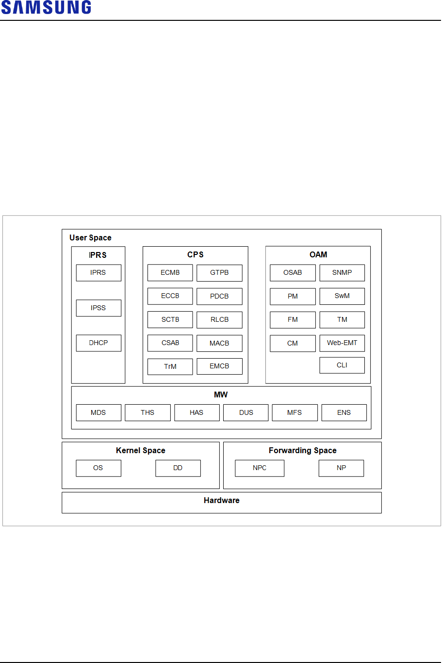
Confidential
Chapter 3 System Structure
LTE eNB System Description v2.0 37
Copyright © 2017, All Rights Reserved.
Software Structure
Basic Software Structure
The software of eNB is divided into three parts:
Kernel Space (OS/DD)
Forwarding Space (NPC, NP)
User Space (MW, IPRS, CPS, OAM)
The following figure shows eNB software structure:
Figure 21. eNB Software Structure
Operating System (OS)
The OS initializes and controls the hardware devices and ensures that software is
ready to run on the hardware devices.
The OS consists of a booter, kernel, root file system (RFS), and utility.
Booter: Performs initialization on boards. It initializes the CPU, L1/L2 Cache,
UART, and MAC and the devices such as CPLD and RAM within each board,
and runs the u-boot.

Confidential
Chapter 3 System Structure
LTE eNB System Description v2.0 38
Copyright © 2017, All Rights Reserved.
Kernel Manages the operation of multiple software processes and provides
various primitives to optimize the use of limited resources.
RFS: Stores and manages the binary files, libraries, and configuration files
necessary for running and operating the software by File-system Hierarchy
Standard 2.2 (FHS).
Utility: Provides the functions for managing the complex programmable logic
device (CPLD), LED, watchdog, and environment and inventory information,
measuring and viewing the CPU load, and storing and managing fault
information when a processor goes down.
Device Driver (DD)
The DD allows applications to operate normally on devices that are not directly
controlled from OS in the system. The DD consists of physical DD and virtual DD.
Physical DD: Provides the interface through which an upper application can
configure, control, and monitor the external devices of the processor. (Switch
device driver and Ethernet MAC driver, and so on.)
Virtual DD: In case of physical network interfaces, virtual interfaces are
created on the kernel so that the upper applications may control the virtual
interfaces instead of controlling the physical network interfaces directly.
Network Processing Control (NPC)
The NPC, via the interfaces with the upper processes such as IPRS and OAM,
constructs and manages various tables necessary for processing packets of the NP
software described above, and performs the network statistics collection function
and the network status management function.
Network Processing (NP)
The NP is the software which processes the packets required for backhaul interface.
The functions of the NP are as follows:
Packet RX and TX
IPv4 and IPv6
Packet RX and TX
IPv4 and IPv6
Packet queuing and scheduling
MAC filtering
IP Packet forwarding
IP fragmentation and reassembly
Link aggregation
VLAN termination

Confidential
Chapter 3 System Structure
LTE eNB System Description v2.0 39
Copyright © 2017, All Rights Reserved.
Access Control List (ACL)
MAC filtering
IP Packet forwarding
IP fragmentation and reassembly
Link aggregation
VLAN termination
ACL (Access Control List)
Middleware (MW)
The MW ensures seamless communication between OS and applications on
various hardware environments. It provides a Message Delivery Service (MDS)
between applications, Debugging Utility Service (DUS), Event Notification
Service (ENS), High Availability Service (HAS) for redundancy management and
data backup, Task Handling Service (THS), and Miscellaneous Function Service
(MFS).
MDS: Provides all services related to message transmitting and receiving.
DUS: Provides the function for transmitting debugging information and
command between applications and operator.
ENS: Adds and manages various events such as timers, and provides the
function for transmitting an event message to destination at the time when it is
needed.
HAS: Provides the data synchronization function and the redundancy state
management function.
THS: Provides the task creation/termination function, task control function,
and function for providing task information, and so on.
MFS: The MFL is responsible for all hardware-dependent functions, such as
accessing physical addresses of hardware devices.
IP Routing Software (IPRS)
The IPRS is the software that provides IP routing and IP security function for eNB
backhaul. The IPRS is configured with IPRS, IP Security Software (IPSS) and
Dynamic Host Configuration Protocol (DHCP), and each of them provide the
functions as follows.
IPRS: Collects and manages the system configuration and status information
necessary for IP routing. Based on this data, IPRS provides the function for
creating routing information.
o Managing Ethernet, VLAN-TE, and link aggregation
o IP addresses management
o IP routing information management
o QoS management
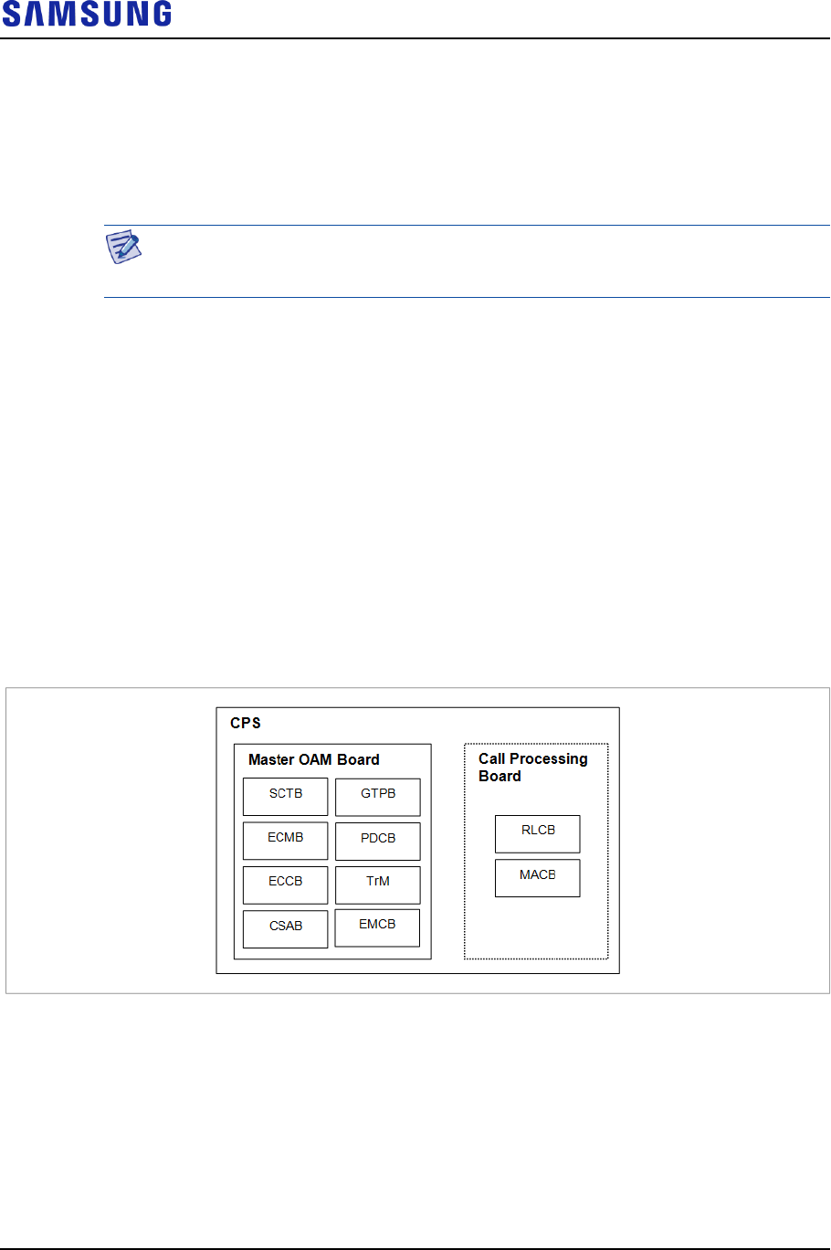
Confidential
Chapter 3 System Structure
LTE eNB System Description v2.0 40
Copyright © 2017, All Rights Reserved.
IPSS: Software that performs the security functions for the IP layer. It is
responsible for filtering based on the IP address, TCP/UDP port number, and
protocol type.
DHCP: Software block that performs the automatic IP address allocation
function. It is responsible for obtaining an IP address automatically by
communicating with DHCP server.
In the following sections, the Master OAM Board and Call Processing Board,
where the software runs on, indicate LMD1 and RFD01P-13A of CDU each.
CPS Block
The Call Processing Software (CPS) block performs resource management of LTE
eNB and call processing function in eNB, which is defined in the 3GPP. Also, CPS
performs the interface function with EPC, UE, and neighbor eNBs. The CPS
consists of eNB control processing subsystem (ECS), which is responsible for
network access and call control functions, and eNB data processing subsystem
(EDS), which is responsible for user traffic handling.
In addition, depending on eNB functions defined in 3GPP, ECS consists of SCTB,
ECMB, ECCB, SCTB, CSAB, TrM, and EMCB. Also, EDS consists of GTPB,
PDCB, RLCB, and MACB.
The following figure shows the CPS structure:
Figure 22. CPS Structure
Stream Control Transmission protocol Block (SCTB)
The SCTB is responsible for establishing S1 interface between eNB and MME,
and establishes X2 interface between neighbor eNBs. It operates on the master
OAM board.
The major functions of SCTB are as follows:
S1 interfacing

Confidential
Chapter 3 System Structure
LTE eNB System Description v2.0 41
Copyright © 2017, All Rights Reserved.
X2 interfacing
eNB Common Management Block (ECMB)
The ECMB performs call processing function such as the system information
transmission and eNB overload control for each eNB and cell. It operates on the
master OAM board.
The major functions of ECMB are as follows:
Setting/Releasing cell
Transmitting system information
eNB overload control
Access barring control
Resource measurement control
Transmission of cell load information
eNB Call Control Block (ECCB)
The ECCB performs the function to control the call procedure until exit after call
setup and call processing function for MME and neighbor eNBs. It operates on the
master OAM board.
The major functions of ECCB are as follows:
Radio resource management
Idle to Active status transition
Setting/changing/releasing bearer
Paging Functions
MME selection/load balancing
Call admission control
Security function
Handover control
UE measurement control
Statistics processing
Call processing function related to the SON (Mobility Robustness, RACH
optimization)
eNB MBMS Control Block (EMCB)
The EMCB performs the function to control call procedure related to eMBMS and
process call with MME or neighbour eNB.
The major functions of EMCB are as follows:

Confidential
Chapter 3 System Structure
LTE eNB System Description v2.0 42
Copyright © 2017, All Rights Reserved.
M3AP function
SFN SYNC function
EMCB statistics processing
MCE troubleshooting
CPS SON Agent Block (CSAB)
The CSAB supports the SON function, which is performed in eNB CPS. It
operates on the master OAM bard.
The major functions of CSAB are as follows:
Mobility robustness optimization
RACH optimization
Mobility load balancing
GPRS Tunneling Protocol Block (GTPB)
The GTPB is the user plane call processing function of eNB. It processes the GTP.
It operates on the master OAM board.
The major functions of GTPB are as follows:
GTP tunnel control
GTP management
GTP data transmission
SYNC protocol
Trace Management (TrM)
The TrM updates the trace data and Call Summary Log (CSL), which are received
from each software entity (PDCP, MAC and RLC). The updated data is
periodically transmitted to LSM. It operates on the master OAM board.
The major functions of TrM are as follows:
Signaling based trace
Cell traffic trace
CSL function
Trace data transmission to the Trace Collection Entity (TCE) address
PDCP Block (PDCB)
The PDCB is the user plane call processing function of eNB. It processes the
PDCP.
It operates on the master OAM board.

Confidential
Chapter 3 System Structure
LTE eNB System Description v2.0 43
Copyright © 2017, All Rights Reserved.
The major functions of PDCB are as follows:
Header compression or decompression (ROHC only)
Transmitting user data and control plane data
PDCP sequence number maintenance
DL/UL data forwarding at handover
Ciphering and deciphering for user data and control data
Control data integrity protection
Timer-based PDCP SDU discarding
Radio Link Control Block (RLCB)
The RLCB is the user plane call processing function of eNB. It processes the RLC
protocol. It operates on the call processing board.
The major functions of RLCB are as follows:
Transmission for the upper layer PDU
ARQ function used for the AM mode data transmission
RLC SDU concatenation, segmentation and reassembly
Re-segmentation of RLC data PDUs
In sequence delivery
Duplicate detection
RLC SDU discard
RLC re-establishment
Protocol error detection and recovery
Medium Access Control Block (MACB)
The MACB is the user plane call processing function of eNB. It processes the
MAC protocol. It operates on the call processing board.
The major functions of MACB are as follows:
Mapping between the logical channel and the transport channel
Multiplexing & de-multiplexing
HARQ
Transport format selection
Priority handling between UEs
Priority handling between logical channels of one UE
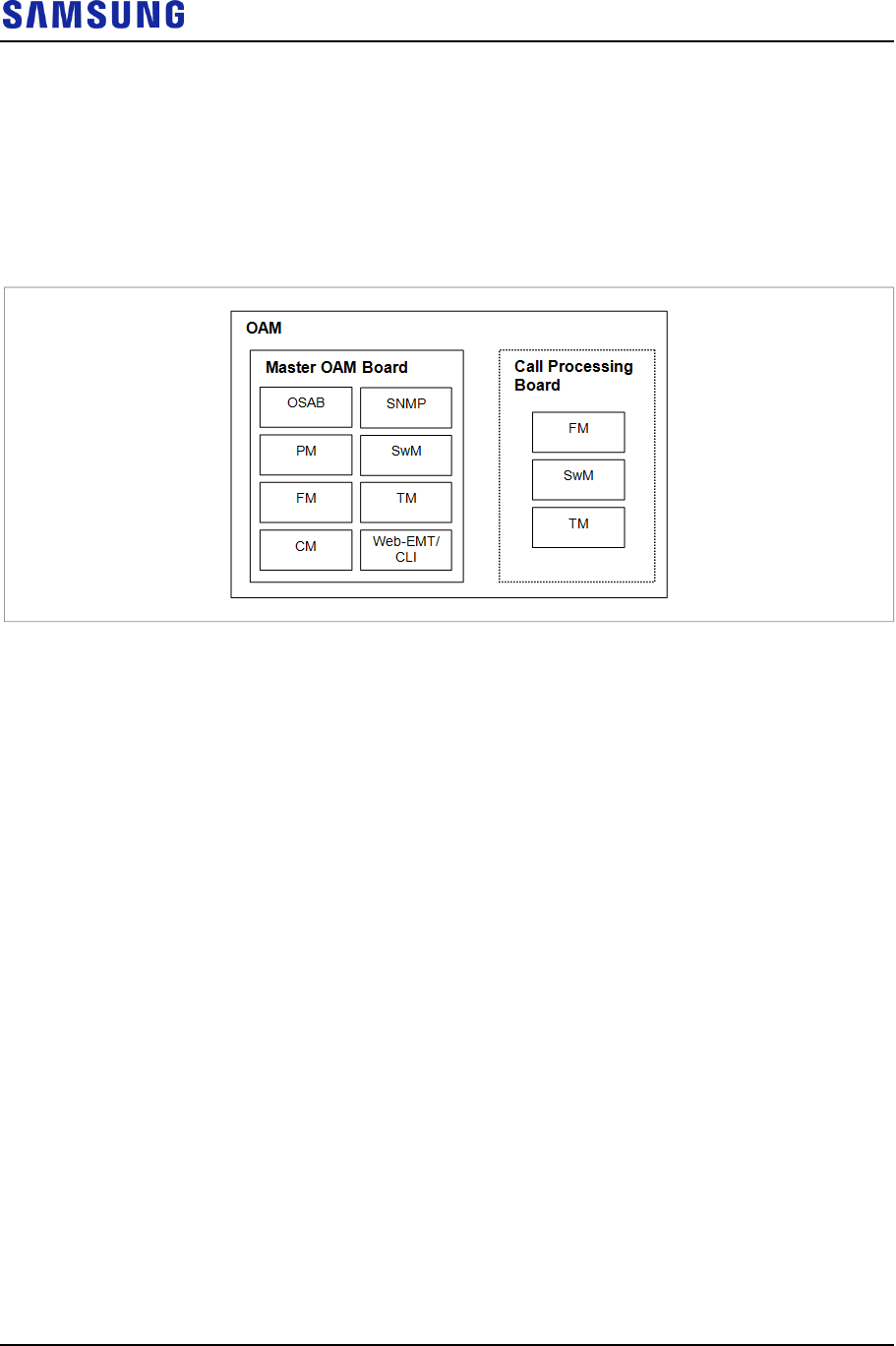
Confidential
Chapter 3 System Structure
LTE eNB System Description v2.0 44
Copyright © 2017, All Rights Reserved.
OAM Blocks
The Operation And Maintenance (OAM) is responsible for operation and
maintenance in eNB.
The OAM is configured with OSAB, PM, FM, CM, SNMP, SwM, TM, Web-EMT,
and CLI.
Figure 23. OAM Structure
The major functions of OAM are as follows:
OAM SON Agent Block (OSAB)
To allow the operator of a management system to perform LTE SON function of
eNB, the OSAB supports the automatic configuration & installation of system
information, and automatic creation & optimization of a neighbor list. The OSAB
operates on the master OAM board.
The main functions of OSAB are as follows:
System information, automatic configuration, and automatic installation
Optimizing automatic neighbor relation
Performance Management (PM)
The PM collects and provides performance data so that the operator of the
management system can determine the performance of LTE eNB. The PM collects
events and performance data during system operation and transmits them to the
management systems. Overall statistics files are generated in binary form every 15
minutes, and these files are collected in the management system via FTP/SFTP on
the regular basis.
The main functions of PM are as follows:
Collecting statistics data
Storing statistics data
Transmitting statistics data

Confidential
Chapter 3 System Structure
LTE eNB System Description v2.0 45
Copyright © 2017, All Rights Reserved.
Fault Management (FM)
The FM performs fault and status management functions on eNB’s hardware and
software. It applies filtering to a detected fault, notifies the management system,
and reflects the fault severity and threshold changes in the fault management. Also,
it operates on the master OAM board and call processing board.
The main functions of FM are as follows:
Detecting faults and reporting alarms
Viewing alarms
Alarm filtering
Setting alarm severity
Setting alarm threshold
Alarm correlation
Status management and reporting
Status retrieval
Configuration Management (CM)
The CM manages eNB configuration and parameters in PLD format and provides
the data that the software blocks need. Through the command received from
SNMP/CLI/Web-EMT, CM provides the functions that can grow/degrow system
configuration, and display/change the configuration data and operation parameters.
The CM operates on the master OAM board.
The main functions of CM are as follows:
Grow/degrow of system and cell
Retrieval, change, grow & degrow of configuration information
Retrieval & change of the call parameters
Retrieval, addition, deletion, and change of neighbors
Simple Network Management Protocol (SNMP)
The SNMP is an SNMP agent for supporting a standard SNMP
(SNMPv2c/SNMPv3).
It performs interfacing with upper management systems and interoperates with the
internal subagents. When receiving a request for a standard MIB object from LSM,
the SNMP processes the request independently. When receiving a request for a
private MIB object, it transmits the request to the corresponding internal subagent.
The SNMP operates on the master OAM board.
The main functions of SNMP are as follows:
Processing the standard MIB
When receiving a request for MIB-II object, the SNMP processes it

Confidential
Chapter 3 System Structure
LTE eNB System Description v2.0 46
Copyright © 2017, All Rights Reserved.
independently and transmits a response.
Processing a private MIB
When receiving a request for a private MIB object, the SNMP does not
process it independently; it transmits the request to the corresponding internal
subagent. Then, SNMPD receives a response from the subagent and transmits
it to the manager.
Soft Ware Management (SwM)
The SwM downloads and runs the package for each board under the file list
downloaded during the preloading procedure. The SwM monitors the software that
has been run, provides information on the running software, and supports software
restart and upgrade according to the command. The SwM operates on the master
OAM board and call processing board.
The main functions of SwM are as follows:
Downloading and installing software and data files
Reset of hardware unit and system
Status monitoring of the software unit in operation
Managing and updating the software and firmware information
Software upgrade
Inventory Management Functions
Test Management (TM)
The TM checks internal and external connection paths of system or the validity of
its resources. The connection paths are classified into system internal IPC path and
external path to other NEs.
Moreover, TM conducts on-demand tests upon operator’s request and periodic
tests according to the schedule set by the operator. The TM operates on the master
OAM board and call processing board.
The main functions of TM are as follows:
Enable/disable the Orthogonal Channel Noise Simulator (OCNS)
Setting/clearing a Model
Ping test
Measuring the Tx/Rx power
Measuring the antenna Voltage Standing Wave Ratio (VSWR)
Web-based Element Maintenance Terminal (Web-EMT)
The Web-EMT is a block used to interface with web client of the console terminal
that uses a web browser. It operates as a web server. The Web-EMT support
highly secured Secure Sockets Layer (SSL) based HTTP communication. The

Confidential
Chapter 3 System Structure
LTE eNB System Description v2.0 47
Copyright © 2017, All Rights Reserved.
Web-EMT operates on the master OAM board.
The main functions of Web-EMT are as follows:
Web server function
Interoperating with other OAM blocks for processing command
Command Line Interface (CLI)
The CLI is a block to interface with a target CLI when it is connected to a console
terminal in the SSH method. The CLI software block processes CLI command and
shows the result. The CLI operates on the master OAM board.
The main functions of CLI are as follows:
CLI user management
Command input and result output
Fault/Status message output
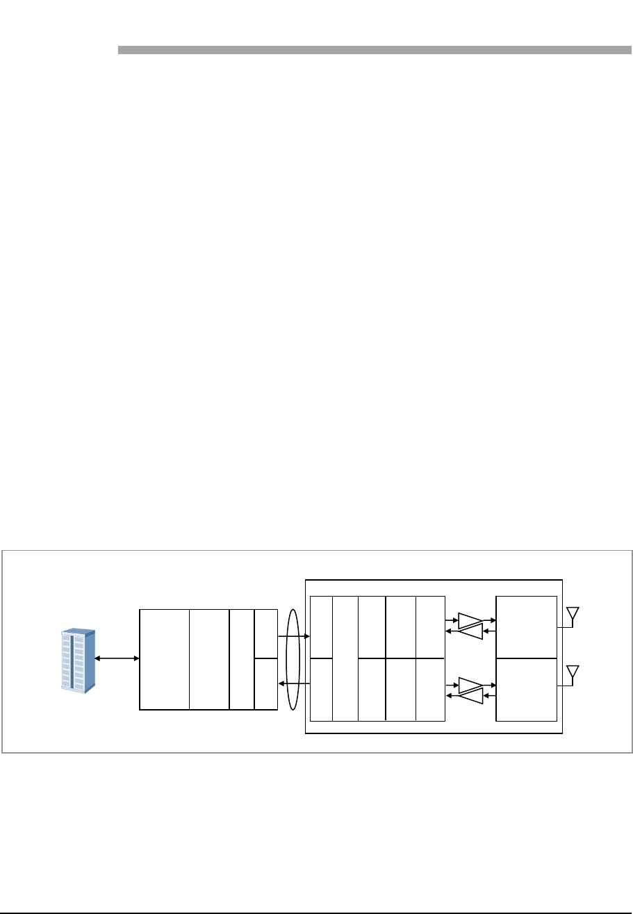
Confidential
LTE eNB System Description v2.0 48
Copyright © 2017, All Rights Reserved.
Chapter 4 Message Flow
Data Traffic Flow
Sending Path
The user data received from EPC passes through the network interface module and
is transmitted through Ethernet switch to CDU. The transmitted user data goes
through baseband-level digital processing before being configured for CPRI, and
then E/O converted. The converted signal is transmitted through the optic cable to
the remote RRH. The RRH performs O/E conversion for a received optic signal.
The converted baseband signal from the wideband is converted into an analog
signal and transmitted through the high-power amplifier, filter, and antenna.
Receiving Path
The RF signal received by the antenna goes through RRH filter and low-noise
amplification by the LNA.
The RF down-conversion and digital conversion are performed for this signal, and
the signal is then converted to a baseband signal. It is configured for CPRI, and
goes through the E-O conversion again.
The converted signal is transmitted through optic cable to the CDU. The data for
which the SC-FDMA signal processing is carried out in the CDU is converted to
the Gigabit Ethernet frame and transmitted from the CDU to EPC via the GE/FE.
Figure 24. Data Traffic Flow
EPC
GE/FE
Main
Processor
Channel
Card
CPRI
conversion
E/O
O/E
RRH
O/E
E/O
DDC/
DUC
A/D
D/A
UP/
Down
DDC/
DUC
A/D
D/A
UP/
Down
BPF
BPF
CDU
CPRI
conversion
Optic
CPRI
PA
LNA
PA
LNA
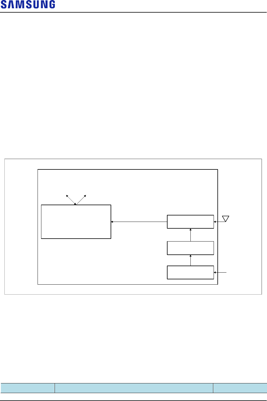
Confidential
Chapter 4 Message Flow
LTE eNB System Description v2.0 49
Copyright © 2017, All Rights Reserved.
Network Sync Flow
The eNB uses GPS and IEEE1588v2 for synchronization. Clock module receives
synchronization signal from the GPS, creates and distributes clocks. For
IEEE1588v2, a processor receives IEEE1588v2 packet from backhaul, and
generate clock through PLL and clock module.
Supported PTP profiles are as below:
IEEE1588v2 unicast negotiation mode (phase)
IEEE1588v2 unicast negotiation mode (frequency)
ITU-T G.8265.1 (frequency)
ITU-T G.8275.1 (phase)
ITU-T G.8275.2
Figure 25. Network Synchronization Flow
Clock
Generation & Distribution Clock module
CDU
GPS
Control
SYS (System Clock 30.72 MHz)
SFN (System Frame Number)
PP2S (Even Clock)
Digital 10 MHz
PP2S (Even Clock)
Processor IEEE1588v2
PLL
control
1PPS
Alarm Signal Flow
An environmental fault or hardware mount/dismount is reported with an alarm
signal, which is collected by LMD1 of the CDU, and reported to LTE System
Manager (LSM). The operator can also provide custom alarms through the UDA.
The following alarms are collected by the LMD1 of CDU:
Table 11. Alarms
Alarm Type
Description
Applicable
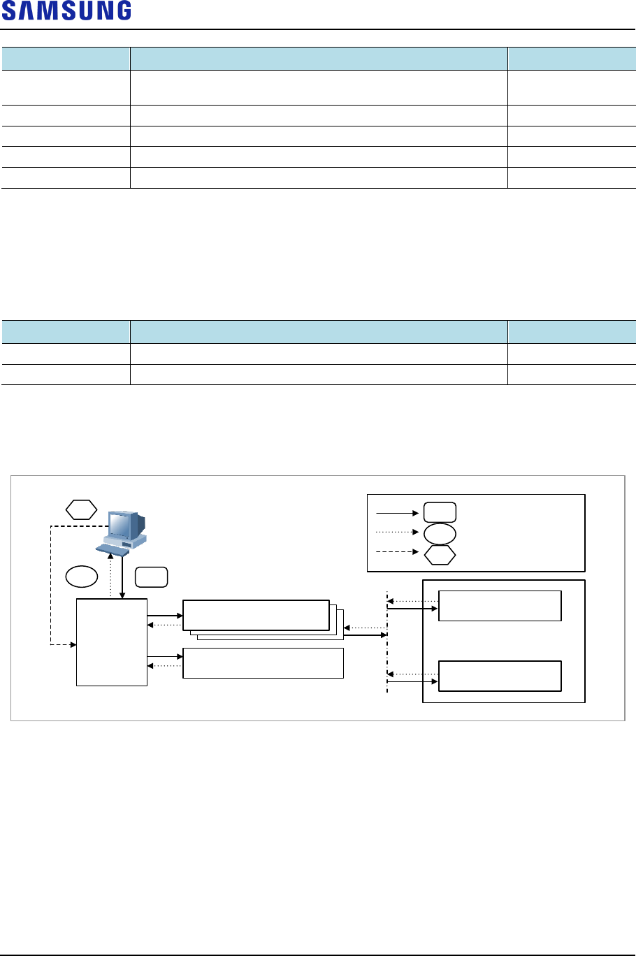
Confidential
Chapter 4 Message Flow
LTE eNB System Description v2.0 50
Copyright © 2017, All Rights Reserved.
Alarm Type
Description
Applicable
Function Fail Alarm
Fault alarm due to software/hardware problems defined as
‘Function Fail’
LCC4-B1A
Power Fail Alarm
Fault alarm due to power problems
LCC4-B1A
Deletion Alarm
System report alarm due to hardware mount/dismount
LCC4-B1A
UDA
Alarm that the operator wants to provide
LMD1-J1A
RF Unit Alarm
RF unit alarm
RRH
Reset command is executed via LSM and transmitted to LMD1. Then, LMD1 reset
itself, lower boards or unit.
The function and types of the reset are as follows:
Table 12. Reset Commands
Alarm Type
Description
Applicable
HW Reset
Reset the board or unit by cutting off the power quickly
LMD1-J1A, RRH
SW Reset
Reset the OS of the LMD1
LMD1-J1A
Figure below depicts alarm flow for LMD1.
Figure 26. Alarm Flow
LMD1
LCC2
LCC2
LCC4
Clock Module
RRH (8)
RRH (0)
.
.
.
A
B
CLSM A
B
C
: Reset
: Alarm
: Remote Pattern Reset
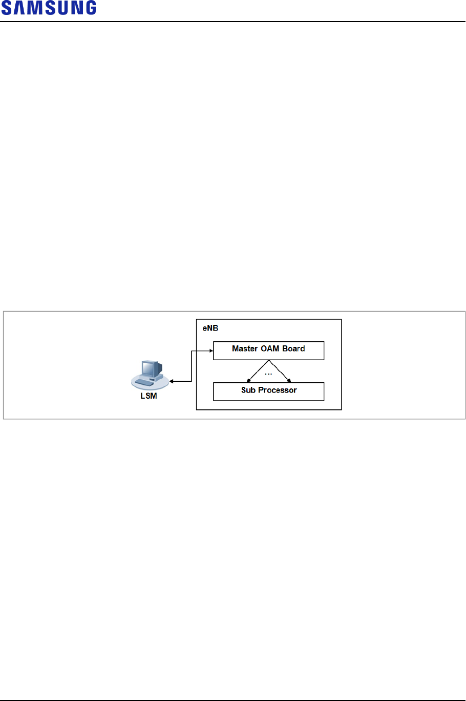
Confidential
Chapter 4 Message Flow
LTE eNB System Description v2.0 51
Copyright © 2017, All Rights Reserved.
Loading Flow
The processors and devices of the system can be downloaded through Loading
procedure from LSM software executables, data, and other elements, which are
required to perform their functions.
During the system initialization procedure, Loading the system is performed.
Loading is also involved when a specific board is mounted in the system, when a
hardware reset is carried out, or when the operator of an upper management
system restarts a specific board.
At the first system initialization, the system is loaded through LSM. As the loading
information is stored in the internal storage, no unnecessary loading is carried out
afterward. After the first system initialization, it compares software files and
versions of LSM and downloads the changed software files.
The loading information contains the software image and default configuration
information file, and so on.
The following figure shows the Loading signal flow:
Figure 27. Loading Signal Flow
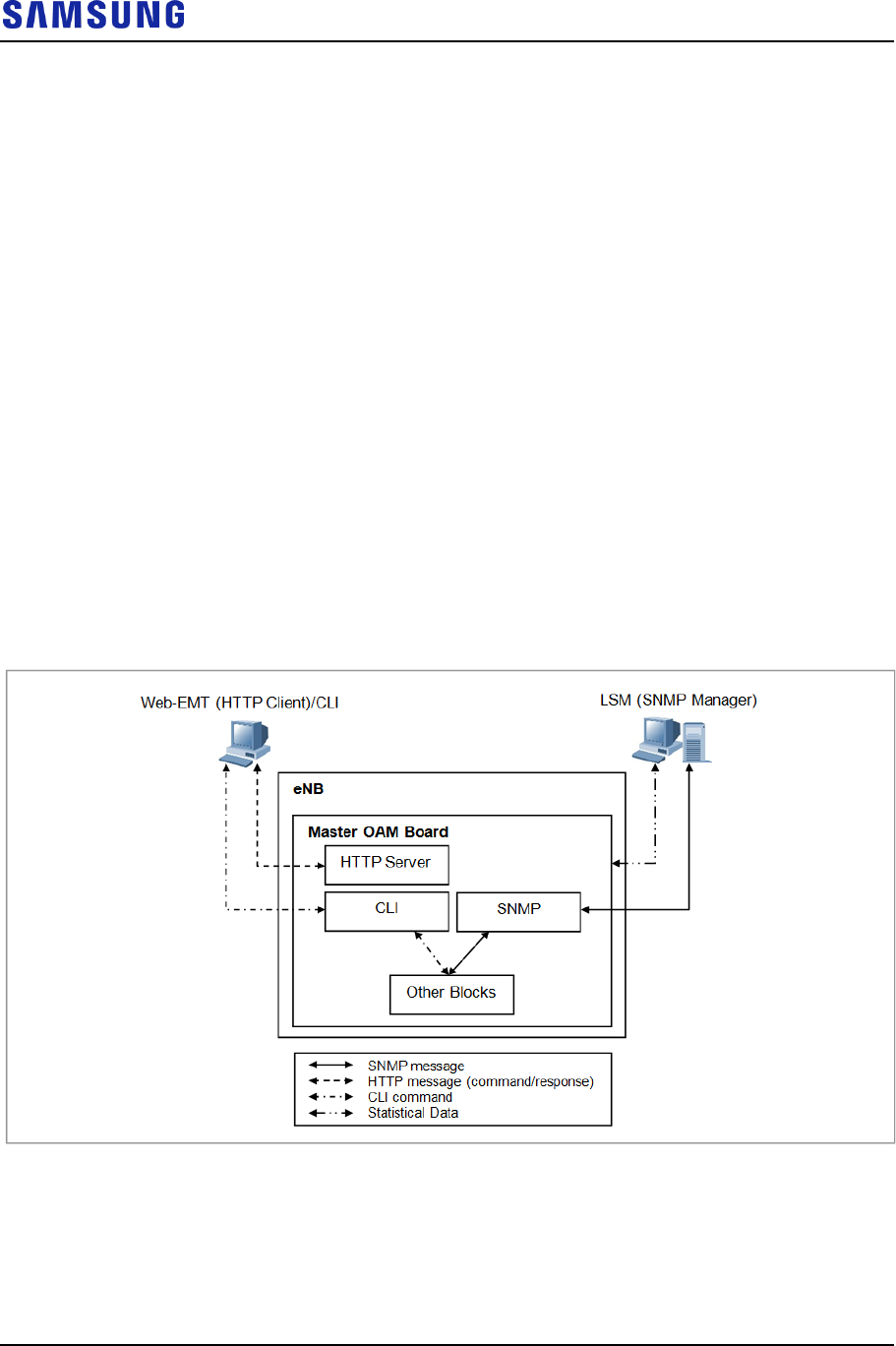
Confidential
Chapter 4 Message Flow
LTE eNB System Description v2.0 52
Copyright © 2017, All Rights Reserved.
Operation and Maintenance Message Flow
The operator can check and change status of eNB through the management system.
To accomplish this, eNB provides the SNMP agent function, and LSM operator
can carry out the operation and maintenance functions of eNB remotely through
the SNMP.
Moreover, operator can carry out maintenance function based on Web-EMT in the
console terminal using web browser. After connecting to telnet or SSH,
maintenance function can be carried out through the CLI.
The statistical information provided by eNB is given to operator by collection
interval.
The operation and maintenance in eNB is performed using the SNMP message
between SNMP agent in the main OAM and the SNMP manager of the LSM.
The eNB processes various operation and maintenance messages received from the
SNMP manager of the management systems. Once processed, eNB transmits their
results to the SNMP manager, and reports the events such as faults and status
changes to the SNMP manager in real-time.
The following figure shows the operation and maintenance signal flow.
Figure 28. Operation and Maintenance Signal Flow
Web-EMT
The Web-EMT is a GUI-based console terminal. It is a tool that monitors the
status of devices and performs operation and maintenance tasks by connecting
directly to eNB. The operator can run the Web-EMT using Internet Explorer,
without installing separate software. The GUI is provided using the HTTPs
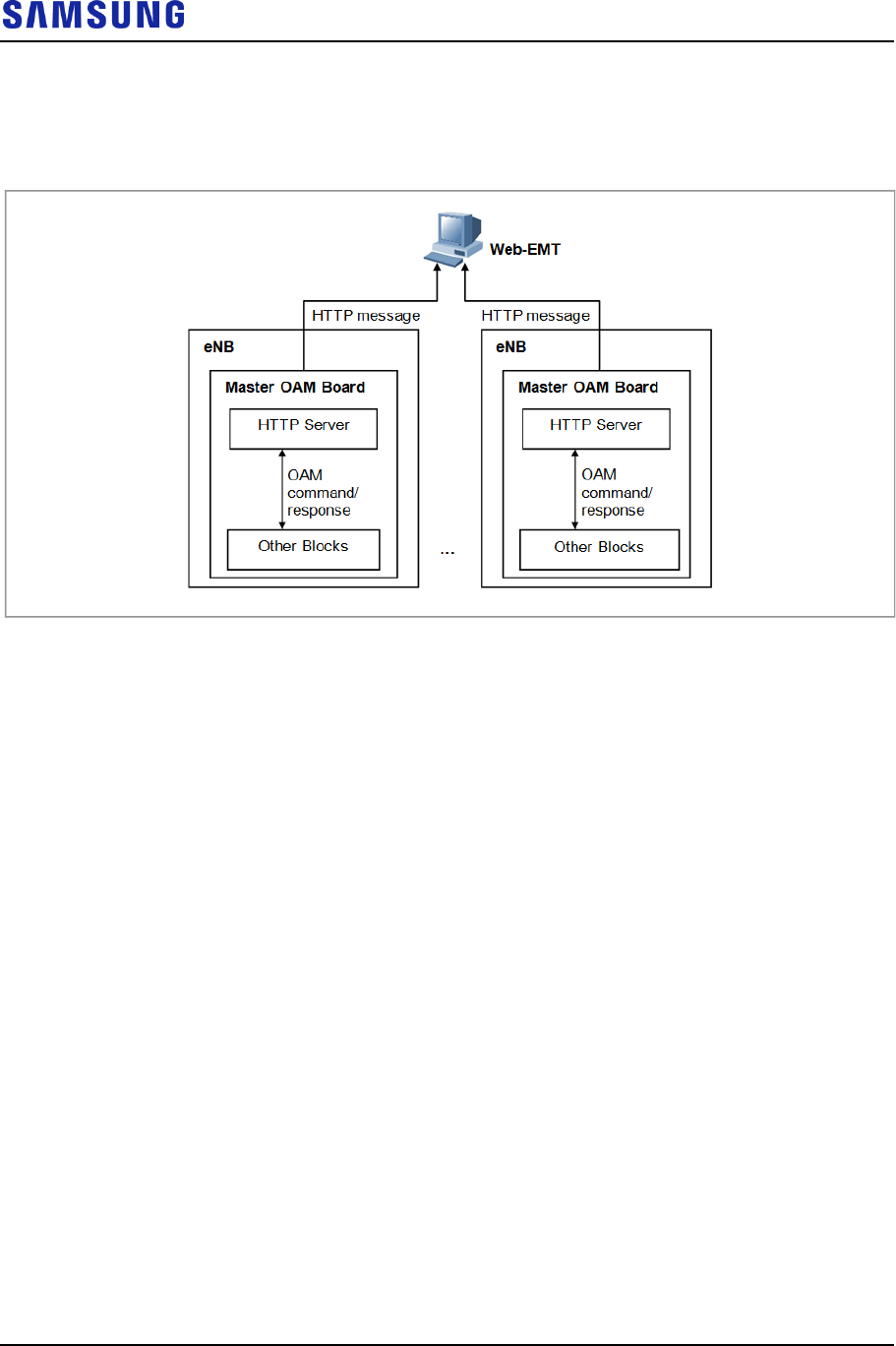
Confidential
Chapter 4 Message Flow
LTE eNB System Description v2.0 53
Copyright © 2017, All Rights Reserved.
protocol internally.
The following figure shows the Web-EMT interface:
Figure 29. Web-EMT Interface
Through Web-EMT, the operator can reset or restart eNB or its internal boards,
view and change the configuration and operation parameter values, monitor the
system status and faults, carry out diagnostic functions, and so on. But the resource
grow and degrow functions and changing the operation information related to
neighbor list are available from LSM only, which manages the entire networks and
the loading images.
CLI
The CLI is the method used for operation or maintenance of eNB. The operator
can perform the text-based operation and maintenance via CLI after login to eNB
via telnet in PC.
The functions of the CLI are as follows:
Loading
The CLI can reset or restart board of eNB.
Configuration Management
The CLI provides the function that executes Man-to-Machine Command (MMC)
that allows viewing and changing the configuration information for eNB.
Status Management
The CLI provides the function that manages status for the processors and various
devices of eNB.

Confidential
Chapter 4 Message Flow
LTE eNB System Description v2.0 54
Copyright © 2017, All Rights Reserved.
Fault Management
The CLI checks whether there are any faults with the processors and various
devices of eNB. Also, it provides the operator with the location and each fault logs.
Since CLI can display both of the hardware and software faults, the operator can
know all faults that occur in eNB.
Diagnosis and Test
The CLI provides the function that diagnoses the connection paths, processors, and
various devices that are being operated in eNB, and provides the test function that
can detect a faulty part. The major test functions that CLI can perform includes,
measuring the transmitting output and the antenna diagnosis function, and so on.

Confidential
LTE eNB System Description v2.0 55
Copyright © 2017, All Rights Reserved.
Appendix Acronyms
3GPP 3rd Generation Partnership Project
256 QAM 256 Quadrature Amplitude Modulation
AC Admission Control
ACL Access Control List
ADC Analog to Digital Converter
AKA Authentication and Key Agreement
AISG Antenna Interface Standards Group
AM Acknowledged Mode
AMBR Aggregated Maximum Bit Rate
ANR Automatic Neighbor Relation
ARQ Automatic Repeat Request
AS Access Stratum
BGP Border Gateway Protocol
BSS Base Station System
C & M Control & Management
CC Chase Combining
CDD Cyclic Delay Diversity
CDU Cabinet DU
CLI Command Line Interface
CM Configuration Management
CoS Class of Service
CP Cyclic Prefix
CPLD Complex Programmable Logic Device
CPRI Common Public Radio Interface
CPS Call Processing Software
CS Circuit Service
CSAB CPS SON Agent Block
CSL Call Summary Log
CSM Core System Manager
DAC Digital to Analog Converter
DBMS Database Management System
DD Device Driver
DDC Digital Down Conversion
DFT Discrete Fourier Transform
DHCP Dynamic Host Configuration Protocol
DiffServ Differentiated Services
DL Downlink
DL-SCH Downlink Shared Channel
DSCP Differentiated Services Code Point
DTM Dual Transfer Mode

Confidential
Appendix Acronyms
LTE eNB System Description v2.0 56
Copyright © 2017, All Rights Reserved.
DU Digital Unit
DUC Digital Up Conversion
DUS Debugging Utility Service
ECCB eNB Call Control Block
ECMB eNB Common Management Block
ECS eNB Control processing Subsystem
EDS eNB Data processing Subsystem
eMBMS enhanced/evolved Multimedia Broadcast Multicast
Services
EMC Electromagnetic Compatibility
EMI Electromagnetic Interference
EMS Element Management System
eNB evolved UTRAN Node B
ENS Event Notification Service
E/O Electric-to-Optic
EPC Evolved Packet Core
EPS Evolved Packet System
E-UTRAN Evolved UTRAN
FANM Fan Module
FE Fast Ethernet
FHS File-system Hierarchy Standard 2.2
FM Fault Management
FPGA Field Programmable Gate Array
FTP File Transfer Protocol
GBR Guaranteed Bit Rate
GE Gigabit Ethernet
GERAN GSM EDGE Radio Access Network
GPRS General Packet Radio Service
GPS Global Positioning System
GPSR GPS Receiver
GTP GPRS Tunnelling Protocol
GTPB GPRS Tunnelling Protocol Block
GTP-U GTP-User
GUI Graphical User Interface
GW Gateway
HARQ Hybrid Automatic Repeat Request
HAS High Availability Service
HO Handover
HSS Home Subscriber Server
HTTP Hypertext Transfer Protocol
HTTPs Hyper Text Transfer Protocol over SSL
ICIC Inter-Cell Interference Coordination
IDFT Inverse Discrete Fourier Transform
IETF Internet Engineering Task Force

Confidential
Appendix Acronyms
LTE eNB System Description v2.0 57
Copyright © 2017, All Rights Reserved.
IP Internet Protocol
IPRS IP Routing Software
IPSS IP Security Software
IPv4 Internet Protocol version 4
IPv6 Internet Protocol version 6
IR Incremental Redundancy
LCC4 LTE Channel card type C2
LMD1 LTE Main card typeD1
LNA Low Noise Amplifier
LSM LTE System Manager
LTE Long Term Evolution
MAC Media Access Control
MACB Medium Access Control Block
MBMS GW Multimedia Broadcast Multicast Service Gateway
MBR Maximum Bit Rate
MBSFN MBMS over a Single Frequency Network
MCS Modulation Coding Scheme
MDS Message Delivery Service
MFS Miscellaneous Function Service
MIB Master Information Block
MIMO Multiple-Input Multiple-Output
MLB Mobility Load Balancing
MMC Man Machine Command
MME Mobility Management Entity
MSC Mobile Switching Center
MSS Master SON Server
MU Multiuser
MW Middleware
NAS Non-Access Stratum
NE Network Element
NP Network Processing
NPC Network Processing Control
NR Neighbor Relation
NRT Neighbor Relation Table
OAM Operation and Maintenance
OCNS Orthogonal Channel Noise Simulator
OCS Online Charging System
O/E Optic-to-Electric
OFCS Offline Charging System
OFDM Orthogonal Frequency Division Multiplexing
OFDMA Orthogonal Frequency Division Multiple Access
OS Operating System
OSAB OAM SON Agent Block
OSPF Open Shortest Path First

Confidential
Appendix Acronyms
LTE eNB System Description v2.0 58
Copyright © 2017, All Rights Reserved.
OSS Operating Support System
PAPR Peak-to-Average Power Ratio
PCEF Policy and Charging Enforcement Function
PCI Physical Cell Identity
PCRF Policy and Charging Rule Function
PDCB PDCP Block
PDCP Packet Data Convergence Protocol
PDN Packet Data Network
PDPM Power Distribution Panel Module
PDU Protocol Data Unit
P-GW PDN Gateway
PLER Packet Loss Error Rate
PM Performance Management
PMIP Proxy Mobile IP
PP2S Pulse Per 2 Seconds
PRACH Physical Random Access Channel
PRB Physical Resource Block
PSS Primary Synchronization Signal
QCI QoS Class Identifier
QoS Quality of Service
QPSK Quadrature Phase Shift Keying
RACH Random Access Channel
RB Radio Bearer
RB Resource Block
RET Remote Electrical Tilting
RF Radio Frequency
RFS Root File System
RLC Radio Link Control
RLCB Radio Link Control Block
RMI Remote Method Invocation
RO RACH Optimization
ROHC Robust Header Compression
RRC Radio Resource Control
RRH Remote Radio Heads
RRM Radio Resource Management
RU Radio Unit

LTE eNB
System Description
Document Version 2.0
© 2017 Samsung Electronics Co., Ltd.
All rights reserved.