Samsung Electronics Co RFV01U-D1A RRU (RFV01U) User Manual 1
Samsung Electronics Co Ltd RRU (RFV01U) 1
UserManual.wiki
>
Samsung Electronics Co
>
RFV01U-D1A User Manual
>
User Manual-1
Contents
1.
User Manual-1
2.
User Manual-2
User Manual-1
Navigation menu
Upload a User Manual
Namespaces
Wiki Guide
HTML
PDF
Info
Views
User Manual
Discussion / Help
Navigation
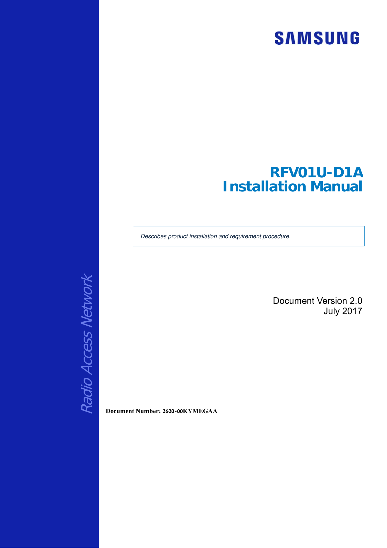
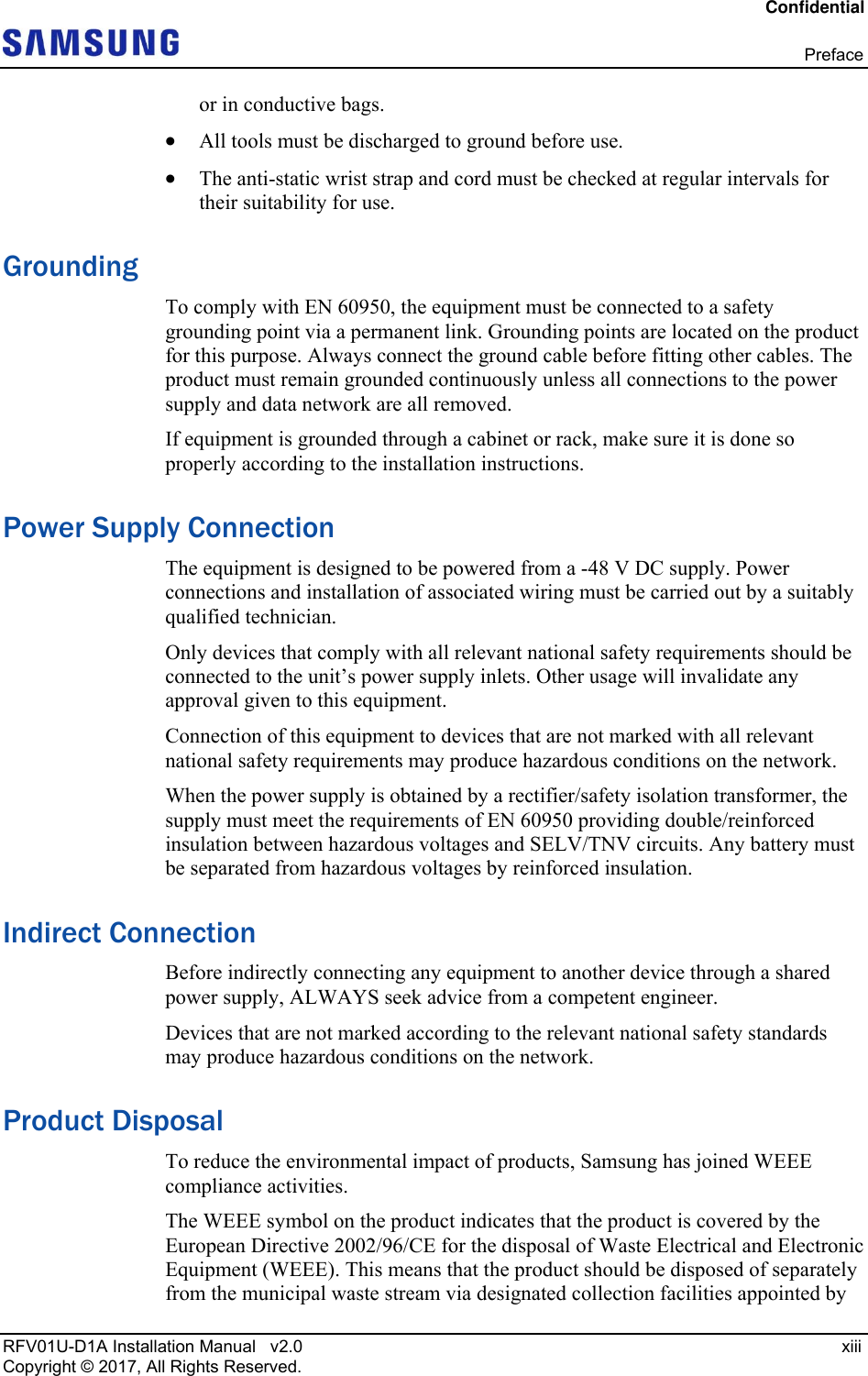
![Confidential RFV01U-D1A Installation Manual v2.0 1 Copyright © 2017, All Rights Reserved. Chapter 1 Before Installation System Configuration and Interface RRH View The view of RRH is as follows. Figure 1. RRH View (without Finger Guard) [Bottom View]14.96 (380) [Front View][Top View] [Left View] [Right View] [Rear View] 19.73 (501.2) 10.04 (255) 14.96 (380) Unit: in. (mm)](https://usermanual.wiki/Samsung-Electronics-Co/RFV01U-D1A.User-Manual-1/User-Guide-3546224-Page-16.png)
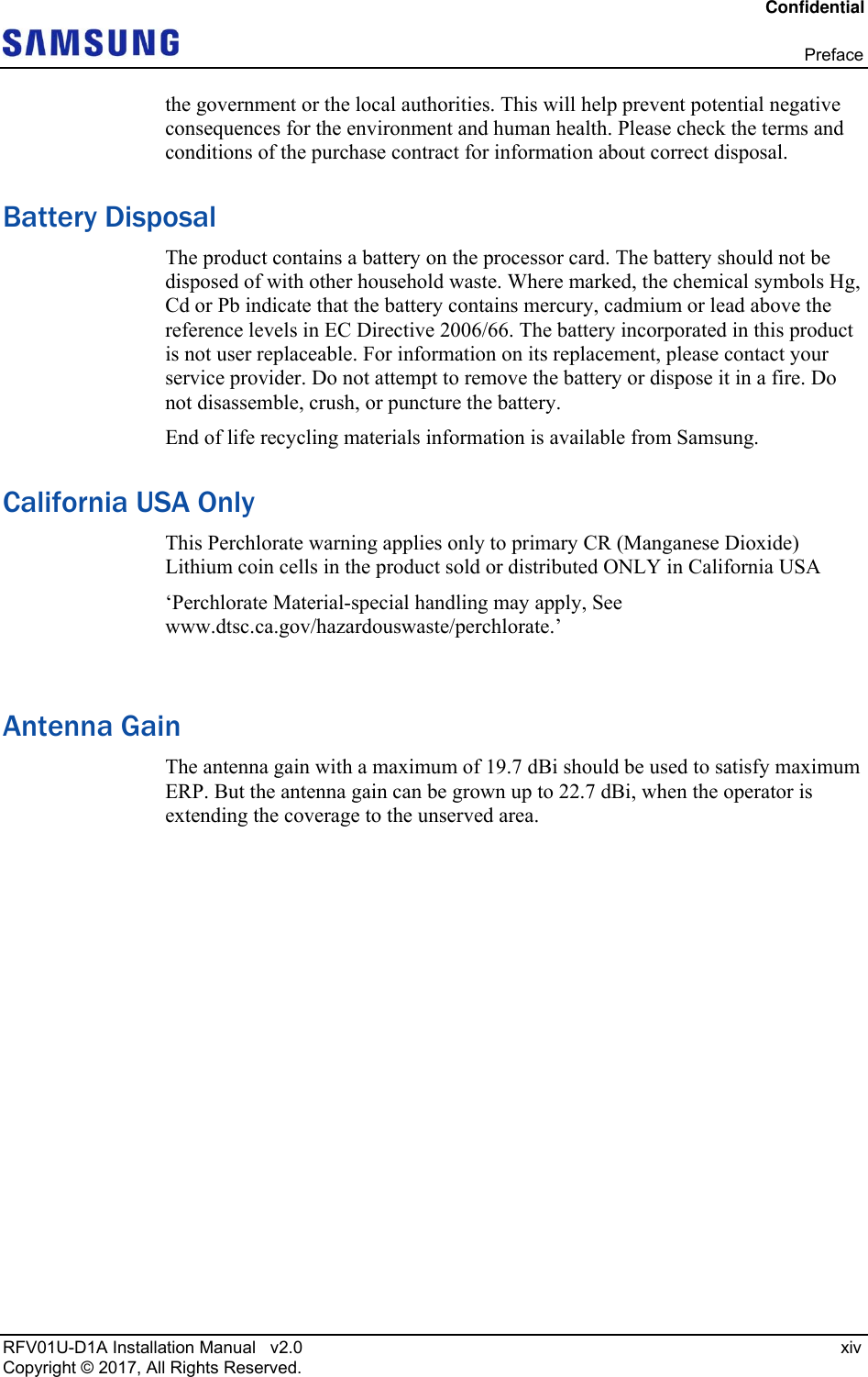
![Confidential Chapter 1 Before Installation RFV01U-D1A Installation Manual v2.0 2 Copyright © 2017, All Rights Reserved. Figure 2. RRH View (with Finger Guard) RRH External Interface The external interface structure of RRH is as follows. [Bottom View]15.49 (393.5) [Front View][Top View] [Left View] [Right View] [Rear View] 19.73 (501) 11.93 (303) 15.88 (403.5) Unit: in. (mm)](https://usermanual.wiki/Samsung-Electronics-Co/RFV01U-D1A.User-Manual-1/User-Guide-3546224-Page-17.png)
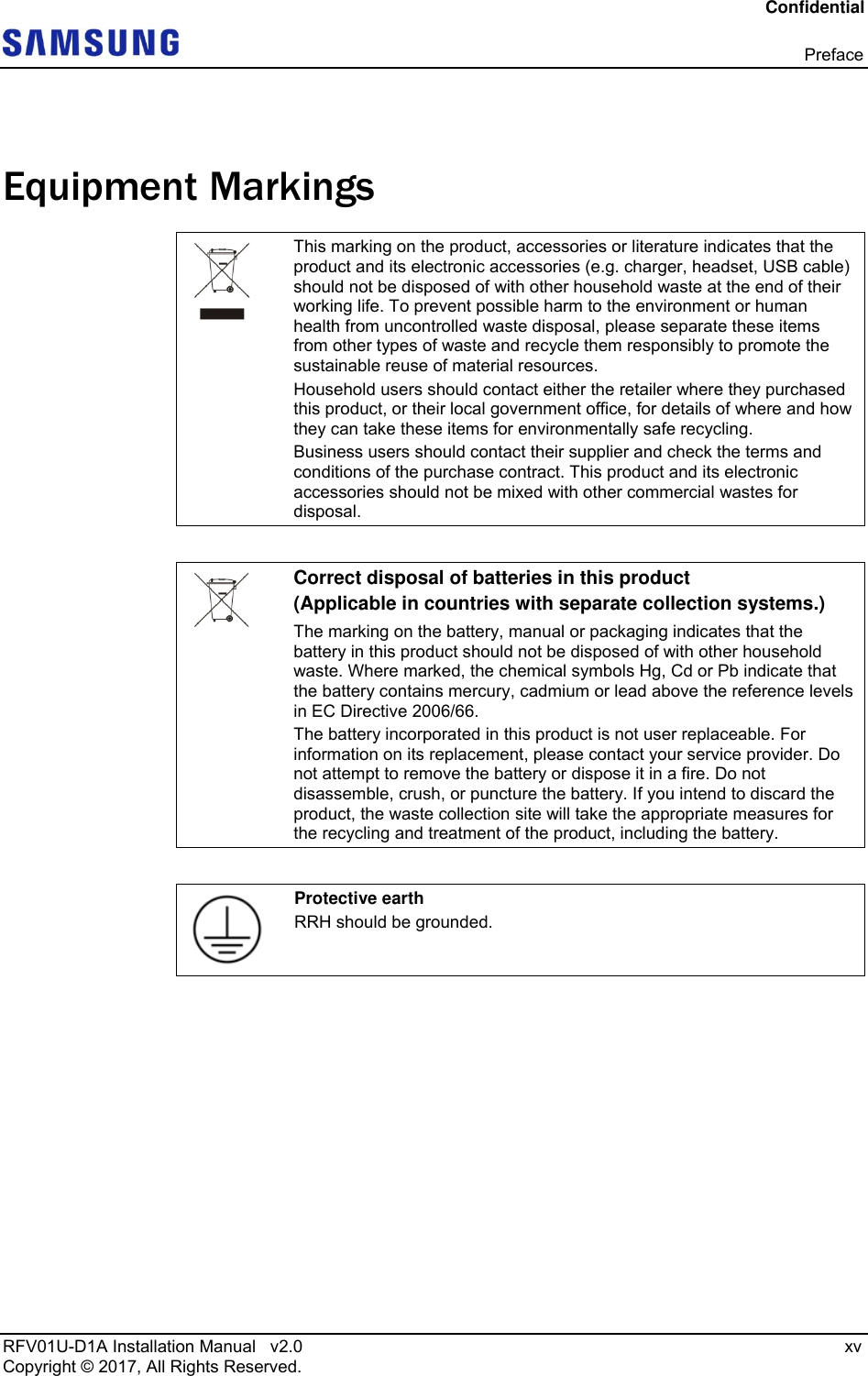
![Confidential Chapter 1 Before Installation RFV01U-D1A Installation Manual v2.0 3 Copyright © 2017, All Rights Reserved. Figure 3. RRH External Interface [Right View]Ground Terminal[Bottom View]ANT 1 (Bias-T) ANT2ANT 3(Bias-T)DC_PWR ANT4RETUDAL0L1ANT 5(Bias-T)ANT 6ANT 7(Bias-T)ANT 8](https://usermanual.wiki/Samsung-Electronics-Co/RFV01U-D1A.User-Manual-1/User-Guide-3546224-Page-18.png)
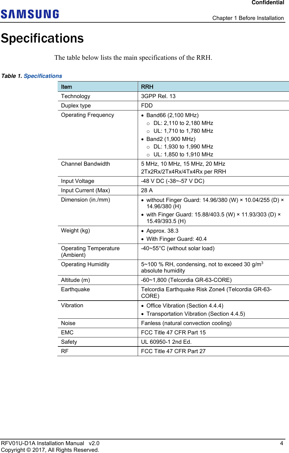
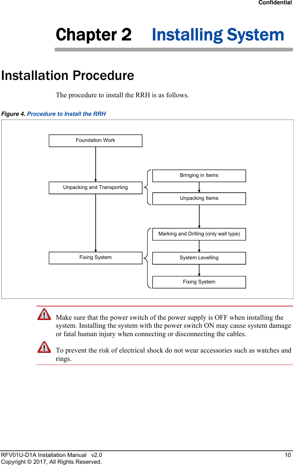
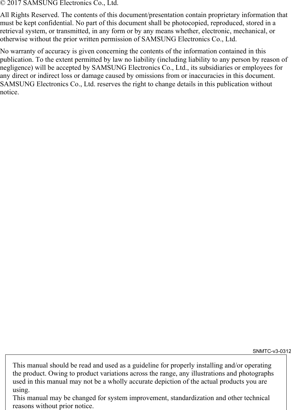
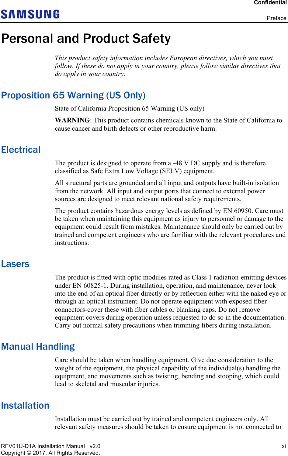
![Confidential Chapter 2 Installing System RFV01U-D1A Installation Manual v2.0 11 Copyright © 2017, All Rights Reserved. System Arrangement A minimum distance must be secured around the RRH, in each direction for installation and maintenance. Figure 5. RRH Arrangement_1 Sector Pole Type Installation (Standard Installation) Figure 6. RRH Arrangement_1 Sector Pole Type Installation (Side Installation) [Front View] Unit: in. (mm)[Top View] ≥ 12 (300) ≥ 16 (400) ≥ 8 (200)≥ 8 (200) 21.26 (540) ≥ 32 (800) W: 15.88 (403.5) H: 19.73 (501.2) [RRH Front]Unit: in. (mm)[Side View] [Top View] ≥ 8 (200)≥ 8 (200) 25.8 (655.4) D: 11.93 (303) H: 19.73 (501.2) ≥12 (300) ≥ 16 (400) ≥ 32 (800)](https://usermanual.wiki/Samsung-Electronics-Co/RFV01U-D1A.User-Manual-1/User-Guide-3546224-Page-26.png)
![Confidential Chapter 2 Installing System RFV01U-D1A Installation Manual v2.0 12 Copyright © 2017, All Rights Reserved. Figure 7. RRH Arrangement_2 Sector Pole Type Installation (Side Installation) When fixing a pole mounting bracket, the length of a carriage bolt is 220 mm for the pole diameter 50~100 A. When 2 sector pole type (side installation) is installed, it is recommended to install it to the pole of the 80 to 100 A specification. Unit: in. (mm)[RRH Front] [Side View] [Top View] ≥ 8 (200) 25.8 (655.4) ≥ 12 (300) ≥ 15.74 (400) ≥ 32 (800) D: 29.84 (758) H: 19.73 (501.2)≥ 8 (200)Pole Size (Diameter) Length of Carriage Bolt 50 A (60.5 mm) 220 mm 65 A (76.3 mm) 80 A (89.2 mm) 90 A (101.6 mm) 100 A (114.3 mm) Pole Size PoleSizeCarriage Bolt Carriage Bolt [1 Sector] [2 Sector]](https://usermanual.wiki/Samsung-Electronics-Co/RFV01U-D1A.User-Manual-1/User-Guide-3546224-Page-27.png)
![Confidential Chapter 2 Installing System RFV01U-D1A Installation Manual v2.0 13 Copyright © 2017, All Rights Reserved. Figure 8. RRH Arrangement_1 Sector Wall Type Installation (Standard Installation) Figure 9. RRH Arrangement_1 Sector Wall Type Installation (Side Installation) [Front View] Unit: in. (mm)[Top View] 14.74 (373.4) ≥ 32 (800) ≥ 12 (300) ≥ 16 (400) ≥ 8 (200) ≥8 (200)W: 15.88 (403.5) H: 19.72 (501.2) [RRH Front]Unit: in. (mm)[Side View] [Top View] 19.25 (489) ≥ 32 (800) ≥ 12 (300) ≥ 16 (400) ≥ 8 (200)≥ 8 (200) D: 11.93 (303) H: 19.72(501.2)](https://usermanual.wiki/Samsung-Electronics-Co/RFV01U-D1A.User-Manual-1/User-Guide-3546224-Page-28.png)
![Confidential Chapter 2 Installing System RFV01U-D1A Installation Manual v2.0 14 Copyright © 2017, All Rights Reserved. Figure 10. RRH Arrangement_3 Sector Wall Type Installation (Standard Installation) [Front View] Unit: in. (mm)[Top View] 14.7 (3734) ≥ 32 (800) ≥ 16 (400) ≥ 12 (300) W: 63.4 (1610.5)/H: 19.73 (501.2) ≥ 8 (200) ≥8 (200)≥ 8 (200) ≥ 8 (200)](https://usermanual.wiki/Samsung-Electronics-Co/RFV01U-D1A.User-Manual-1/User-Guide-3546224-Page-29.png)
![Confidential Chapter 2 Installing System RFV01U-D1A Installation Manual v2.0 15 Copyright © 2017, All Rights Reserved. Figure 11. RRH Arrangement_3 Sector Wall Type Installation (Side Installation) [RRH Front][Front View] Unit: in. (mm)[Top View] ≥ 32 (800) 19.25 (489) ≥ 16 (400) W: 51.54 (1309)/H: 19.73 (501.2) ≥8 (200) ≥8 (200) ≥8 (200) ≥ 8 (200) ≥ 12 (300)](https://usermanual.wiki/Samsung-Electronics-Co/RFV01U-D1A.User-Manual-1/User-Guide-3546224-Page-30.png)
![Confidential Chapter 2 Installing System RFV01U-D1A Installation Manual v2.0 18 Copyright © 2017, All Rights Reserved. Fixing RRH Fixing Finger Guard To fix Finger Guard 1 Make sure you have the following items: Table 3. Parts and Tools for fixing Finger Guard Category Description Parts Finger Guard_Front 1 EA/RRH Finger Guard_Rear 1 EA/RRH Finger Guard_Bottom 1 EA/RRH Fastener M3 × 10L Screw 4 EA/RRH M5 × 10L SEMS 12 EA/RRH Recommended Torque Value M3 Screw 5.6 lbf·in (6.4 kgf·cm) M5 SEMS 25 lbf·in (29 kgf·cm) Working Tools Torque Driver (2~10 lbf·in, 20~90 lbf·in), Screw Driver Bit ('+', No. 2), Screw Driver ('+', No. 2) Check the type and fixing location of Finger guard before fixing it. 2 Place a finger guard_front to the RRH front. [Finger Guard_Rear] [Finger Guard_Front][Finger Guard_Bottom]](https://usermanual.wiki/Samsung-Electronics-Co/RFV01U-D1A.User-Manual-1/User-Guide-3546224-Page-33.png)
![Confidential Chapter 2 Installing System RFV01U-D1A Installation Manual v2.0 19 Copyright © 2017, All Rights Reserved. Figure 13. Finger Guard Fixing (1) 3 Fix the finger guard_front using fasteners. Figure 14. Finger Guard Fixing (2) 4 Place a finger guard_rear to the RRH rear. Figure 15. Finger Guard Fixing (3) 5 Fix the finger guard_rear using fasteners. [RRH Front] Finger Guard_Front [Front Side View] M5 SEMS[RRH Front]Finger Guard_Rear[RRH Rear]](https://usermanual.wiki/Samsung-Electronics-Co/RFV01U-D1A.User-Manual-1/User-Guide-3546224-Page-34.png)
![Confidential Chapter 2 Installing System RFV01U-D1A Installation Manual v2.0 20 Copyright © 2017, All Rights Reserved. Figure 16. Finger Guard Fixing (4) 6 Place a finger guard_bottom to the RRH bottom. Figure 17. Finger Guard Fixing (5) 7 Fix the finger guard_bottom using fasteners. Figure 18. Finger Guard Fixing (6) [RRH Rear][Rear Side View] M5 SEMS[RRH Rear] Finger Guard_Bottom [RRH Rear] [Bottom Side View] M3 Screw](https://usermanual.wiki/Samsung-Electronics-Co/RFV01U-D1A.User-Manual-1/User-Guide-3546224-Page-35.png)
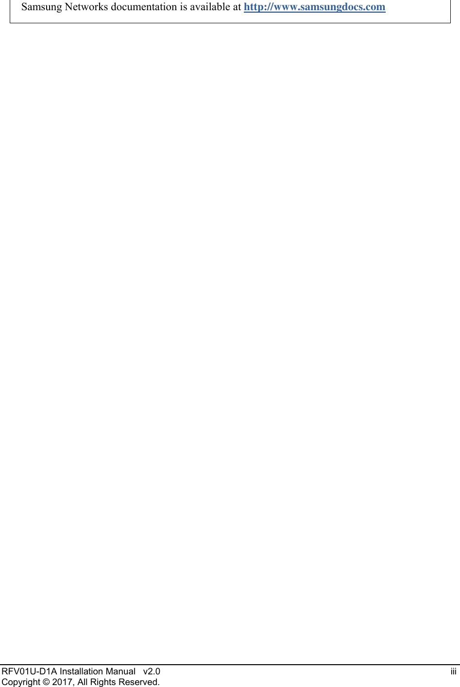
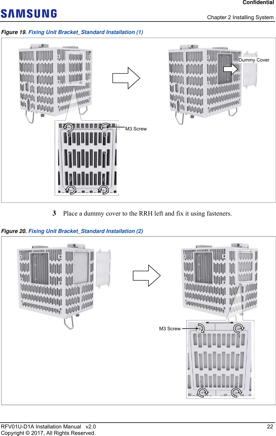
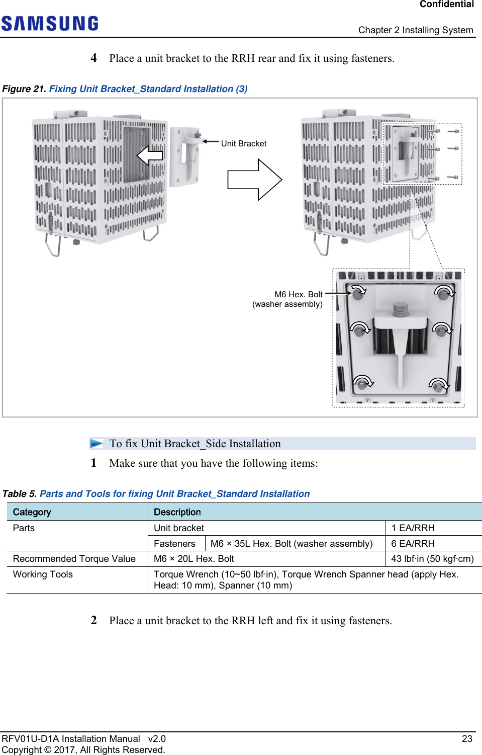
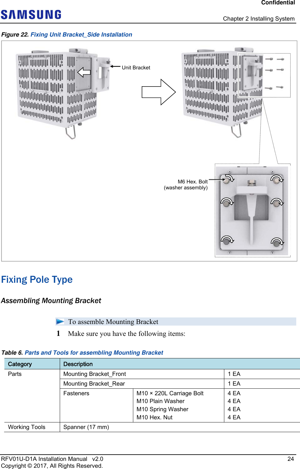
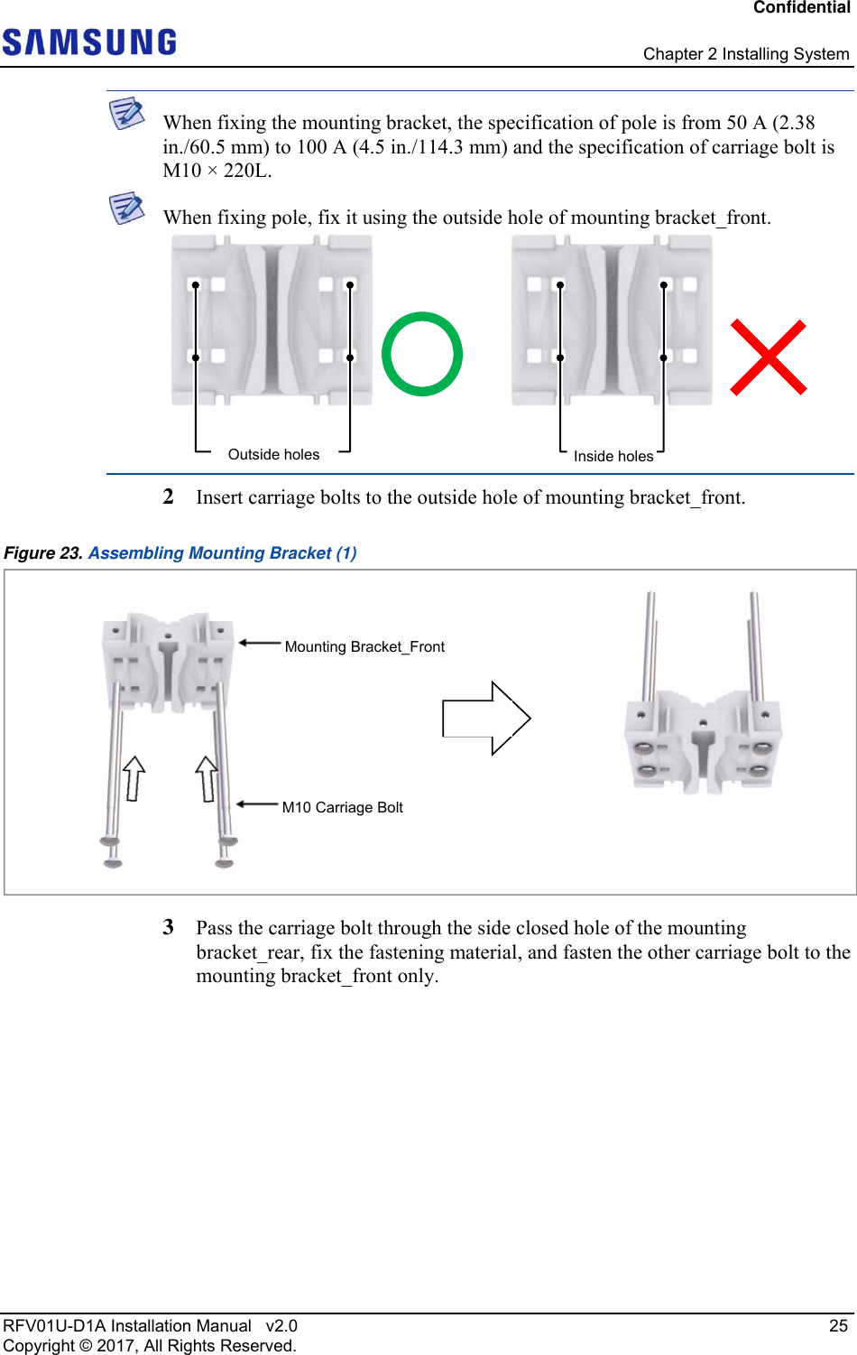
![Confidential Chapter 2 Installing System RFV01U-D1A Installation Manual v2.0 21 Copyright © 2017, All Rights Reserved. Fixing Unit Bracket There are two ways to fix a unit bracket to the RRH. One is fixing a unit mounting bracket to the rear side of RRH (Standard installation). The other is fixing a unit bracket to the side of RRH (Side installation). These are the same for the wall type and pole type installation procedures. To fix Unit Bracket_Standard Installation 1 Make sure that you have the following items: Table 4. Parts and Tools for fixing Unit Bracket_Standard installation Category Description Parts Unit bracket 1 EA/RRH Fasteners M6 × 35L Hex. Bolt (washer assembly) 6 EA/RRH Recommended Torque Value M3 Screw 5.6 lbf·in (6.4 kgf·cm) M6 Hex. Bolt 43 lbfin (50 kgf·cm) Working Tools Torque Wrench (10~50 lbfin), Torque Wrench Spanner head (apply Hex. Head: 10 mm), Spanner (10 mm), Torque Driver (2~10 lbfin), Screw Driver Bit ('+', No. 2), Screw Driver ('+', No. 2) 2 Loosen a fastener of finger guard_rear and separate the dummy cover from it. [Unit Bracket Standard Installation] Unit Bracket (RRH left) Unit Bracket(RRH rear)[Unit Bracket Side Installation]](https://usermanual.wiki/Samsung-Electronics-Co/RFV01U-D1A.User-Manual-1/User-Guide-3546224-Page-36.png)
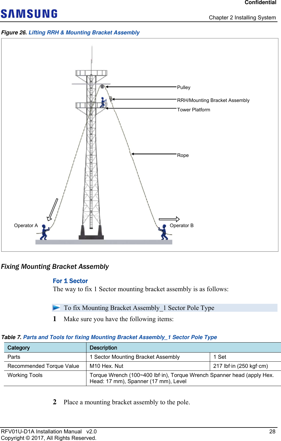
![Confidential Chapter 2 Installing System RFV01U-D1A Installation Manual v2.0 27 Copyright © 2017, All Rights Reserved. Figure 25. Lifting RRH & Mounting Bracket Assembly 2 While Operator A hauls the rope to carry up the RRH/mounting bracket assembly, Operator B pulls the rope outward so that RRH/mounting bracket assembly would not hit the tower platform. [Lifting Mounting Bracket Assembly] [Lifting RRH]Carrying Point_1Carrying Point 2 Carrying Point_1 Carrying Point_2](https://usermanual.wiki/Samsung-Electronics-Co/RFV01U-D1A.User-Manual-1/User-Guide-3546224-Page-42.png)
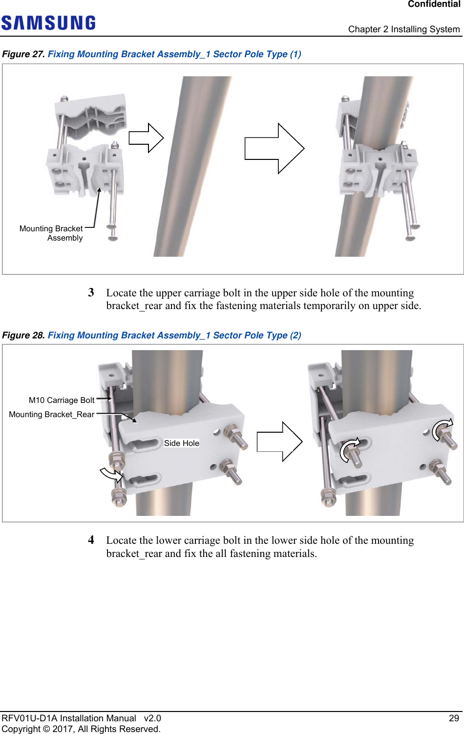
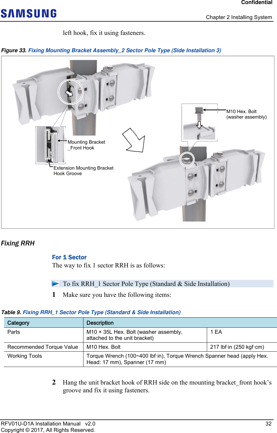
![Confidential Chapter 2 Installing System RFV01U-D1A Installation Manual v2.0 30 Copyright © 2017, All Rights Reserved. Figure 29. Fixing Mounting Bracket Assembly_1 Sector Pole Type (3) 5 Check the level of mounting bracket assembly on a pole and adjust the level. Figure 30. Levelling Mounting Bracket Assembly_1 Sector Pole Type When fixing the pole mounting bracket assembly on a pole, be sure to check the level of bracket. After finishing the installation, you can adjust the level minutely. When occurring poor levelling, adjust the position of fasteners used to fix the Mounting bracket assembly or its levelling status. For 2 Sector The way to fix 2 Sector mounting bracket assembly is as follows: To fix Mounting Bracket Assembly_2 Sector Pole Type (Side Installation) 1 Make sure you have the following items: Side HoleM10 Carriage BoltMounting Bracket_Rear If it is level, the bubble of the spirit level is positioned at the center of both lines. [1 Sector Side & Standard Mounting Bracket Assembly]](https://usermanual.wiki/Samsung-Electronics-Co/RFV01U-D1A.User-Manual-1/User-Guide-3546224-Page-45.png)
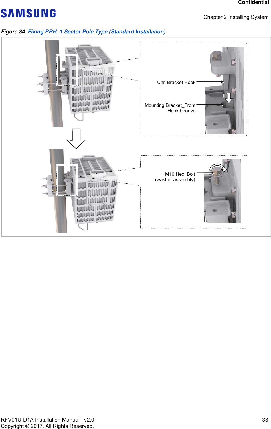
![Confidential Chapter 2 Installing System RFV01U-D1A Installation Manual v2.0 35 Copyright © 2017, All Rights Reserved. Fix the RRH according to the order of [RRH-0 RRH-1]. 2 Hang the unit bracket hook of RRH-0 side on the mounting bracket_front hook’s groove and fix it using fasteners. RRH-0 RRH-1RRH-1RRH-0](https://usermanual.wiki/Samsung-Electronics-Co/RFV01U-D1A.User-Manual-1/User-Guide-3546224-Page-50.png)
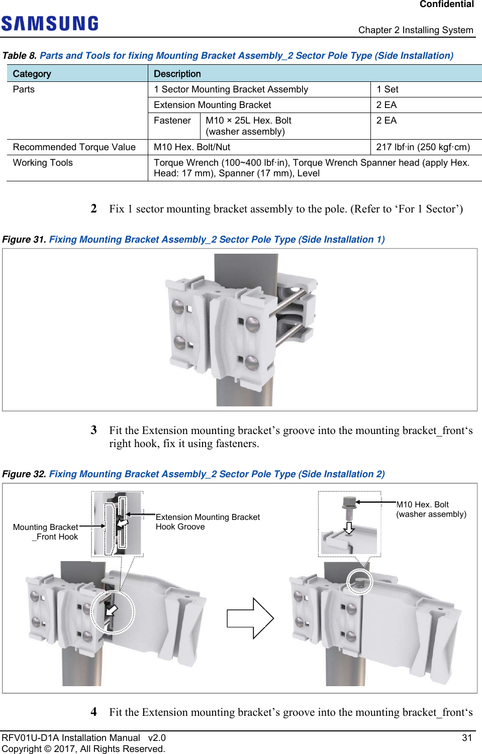
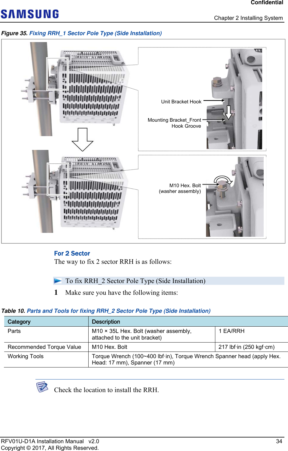
![Confidential Chapter 2 Installing System RFV01U-D1A Installation Manual v2.0 36 Copyright © 2017, All Rights Reserved. Figure 36. Fixing RRH_2 Sector Pole Type (Side Installation 1) 3 Fix RRH-1 in the same way as the RRH-0. Figure 37. Fixing RRH_2 Sector Pole Type (Side Installation 2) Fixing Wall Type Marking and Drilling for Wall Mounting To mark on a wall 1 Make sure you have the following items: [RRH-0][RRH-0]M10 Hex. Bolt(washer assembly)Unit Bracket HookMounting Bracket_FrontHook Groove[RRH-0] [RRH-0] [RRH-1]](https://usermanual.wiki/Samsung-Electronics-Co/RFV01U-D1A.User-Manual-1/User-Guide-3546224-Page-51.png)
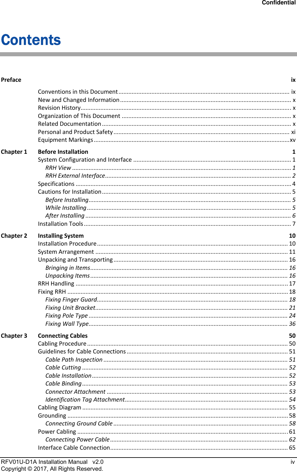
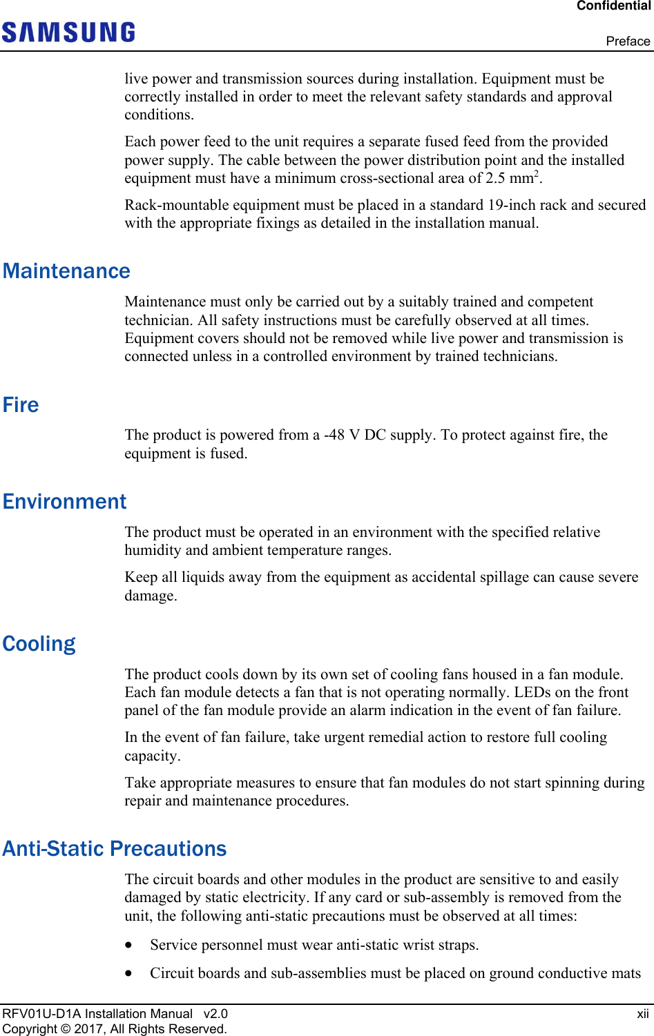
![Confidential Chapter 2 Installing System RFV01U-D1A Installation Manual v2.0 37 Copyright © 2017, All Rights Reserved. Table 11. Tools for Marking Category Description Working Tools Tape Measure, Permanent Maker, Level To mount the system on a wall, perform the leveling test by referring to System Leveling to check the positions are marked to be horizontal or vertical before drilling. If the result shows they are not horizontal or vertical, modify the marking positions. When the position where the system will be placed is determined, place the system on that position and then mark the positions where anchor bolts will be fixed. This will reduce marking error range. 2 Check the distance between the location for fixing the RRH and anchor bolt hole. Figure 38. RRH marking dimensions_1 Sector Wall Type (Standard Installation) [Rear View] Unit: in. (mm) 4.48 (114) 5.12 (130)15.88 (403.5)5.47 (139) 5.28 (134)19.73 (501.2) : Anchor Bolt Hole 2.36 (60)](https://usermanual.wiki/Samsung-Electronics-Co/RFV01U-D1A.User-Manual-1/User-Guide-3546224-Page-52.png)
![Confidential Chapter 2 Installing System RFV01U-D1A Installation Manual v2.0 38 Copyright © 2017, All Rights Reserved. Figure 39. RRH marking dimensions_1 Sector Wall Type (Side Installation) Figure 40. RRH marking dimensions_3 Sector Wall Type (Standard Installation) Unit: in. (mm) : Anchor Bolt Hole [Side View] 5.12 (130)11.93 (303) 3.8 (96.5) 3.01 (76.5)4.48 19.73 (501.2) 2.36 (60) (114) Unit: in. (mm) : Anchor Bolt Hole [Rear View] 5.12 (130)15.88 (403.5) 5.28 (134)≥ 63.4 (1610) ≥ 8 (200)5.47 (139)4.48 (114) 19.73 (501.2) ≥ 8 (200) 2.36 (60)](https://usermanual.wiki/Samsung-Electronics-Co/RFV01U-D1A.User-Manual-1/User-Guide-3546224-Page-53.png)
![Confidential Chapter 2 Installing System RFV01U-D1A Installation Manual v2.0 39 Copyright © 2017, All Rights Reserved. Figure 41. RRH marking dimensions_3 Sector Wall Type (Side Installation) 3 Place a mounting bracket on the fixing location, Check the level status using a level and adjust the level of bracket assembly. 4 If the level status is normal, mark the anchor bolt holes on a wall. Unit: in. (mm) : Anchor Bolt Hole4.48 (114) 19.73 (501.2) [Side View] ≥ 51.54 (1309) ≥ 8 (200)≥ 8 (200)11.93 (303)5.12 (130)3.8 (96.5)3.01 (76.5)2.36 (60)](https://usermanual.wiki/Samsung-Electronics-Co/RFV01U-D1A.User-Manual-1/User-Guide-3546224-Page-54.png)
![Confidential Chapter 2 Installing System RFV01U-D1A Installation Manual v2.0 40 Copyright © 2017, All Rights Reserved. Figure 42. Marking_Wall Type To drill anchor holes and fix anchors 1 Make sure you have the following items: Table 12. Parts and Tools for Drilling & Anchoring Category Description Parts 1, 3 Sector Installation M10 Strong Anchor 4 EA/RRH Woking Tools Hammer Drill, Concrete Drill Bit [0.55 in. (14 mm)], Vacuum Cleaner, Hammer, Anchor Punch (For M10 Strong Anchor) If it is level, the bubble of the spirit level is positioned at the center of both lines. [1 Sector Side & Standard Mounting Bracket Assembly] 5.11 (130)[3 Sector Standard Installation Mounting Bracket Assembly] ≥ 18.64 (473) Unit: in. (mm)/ : Marking Point 2.36 (60) ≥ 18.64 (473) [3 Sector Side Installation Mounting Bracket Assembly] ≥ 14.69 (373) ≥ 14.69 (373)](https://usermanual.wiki/Samsung-Electronics-Co/RFV01U-D1A.User-Manual-1/User-Guide-3546224-Page-55.png)
![Confidential Chapter 2 Installing System RFV01U-D1A Installation Manual v2.0 41 Copyright © 2017, All Rights Reserved. Table 13. Anchor Bolt Drill Bits and Hole Depth Category Anchor Bolt Drill Bits Hole Depth RRH (Wall Type) M10 0.55 in. (14 mm) 1.73 in. (44 mm) 2 Drill anchor holes at marked points with removing dust from the holes using a cleaner. Fix strong anchor to the drilled hole. Figure 43. Drilling & Anchoring When fixing the mounting bracket_front or 2 sector mounting bracket assembly_front on a wall, ‘A’ side should stick on the wall. [O] * Remove the debris from the drilled hole. [Anchor Hole Cross Section] 1.73 in.(44 mm)[X] 0.55 in. (14 mm) Hammer DrillVacuum Cleaner 0.55 in.(14 mm)M10 Strong AnchorAnchor PunchHammer [Top View] A Wall Mounting Bracket_Front A](https://usermanual.wiki/Samsung-Electronics-Co/RFV01U-D1A.User-Manual-1/User-Guide-3546224-Page-56.png)