Samsung Electronics Co S750E Notebook Computer, 366MHz Pentium II User Manual manual
Samsung Electronics Co Ltd Notebook Computer, 366MHz Pentium II manual
UserManual.wiki
>
Samsung Electronics Co
>
S750E User Manual
manual
Navigation menu
Upload a User Manual
Namespaces
Wiki Guide
HTML
PDF
Info
Views
User Manual
Discussion / Help
Navigation


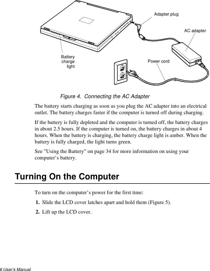
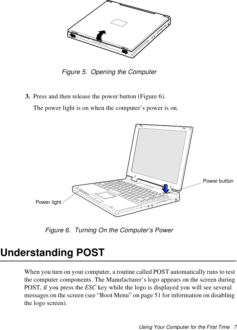
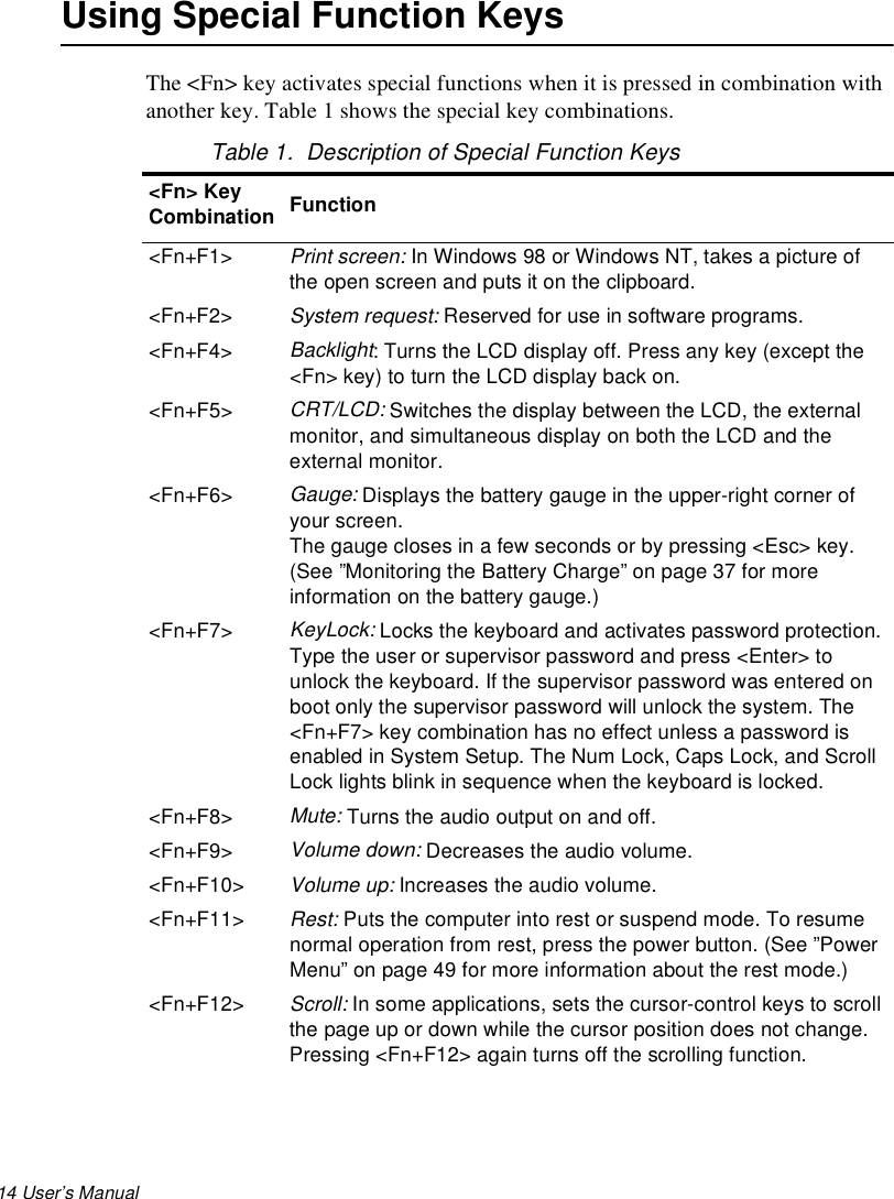
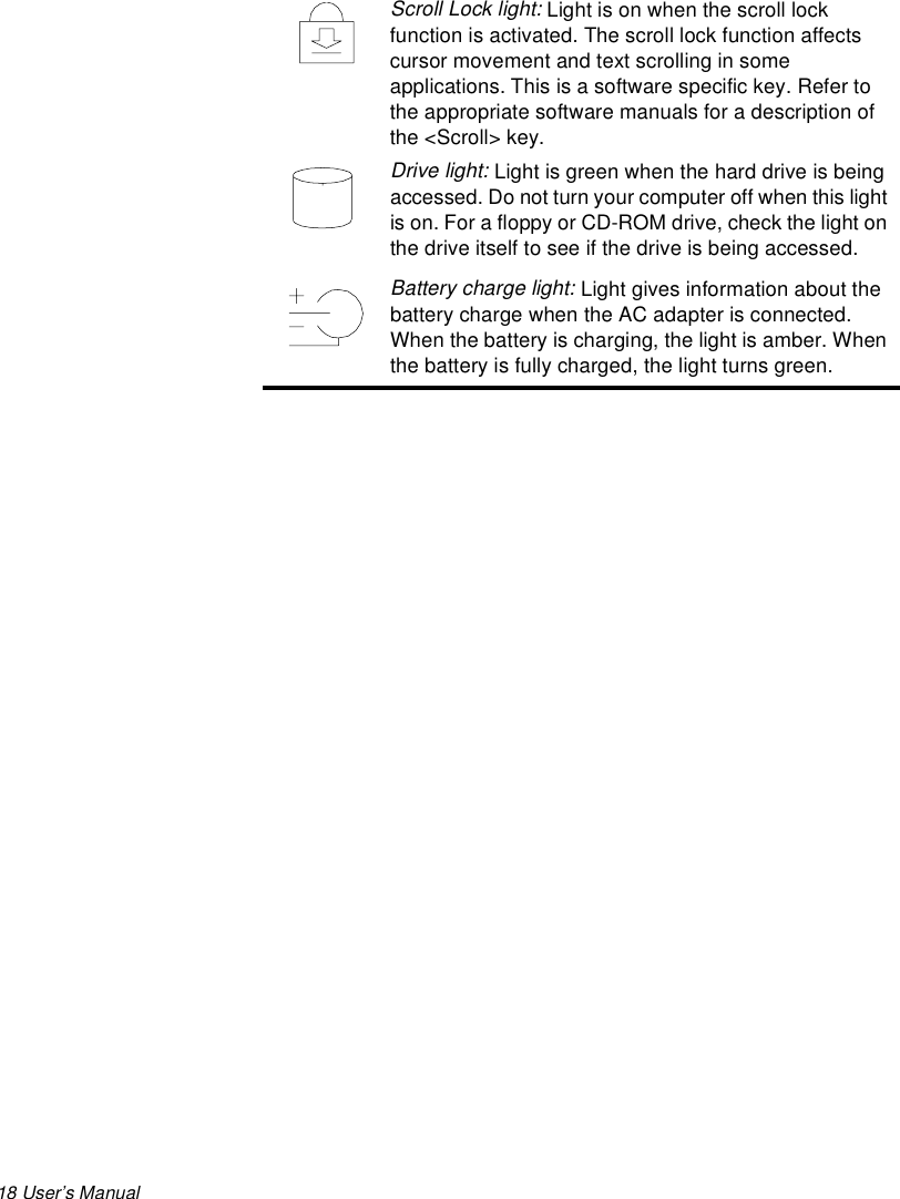
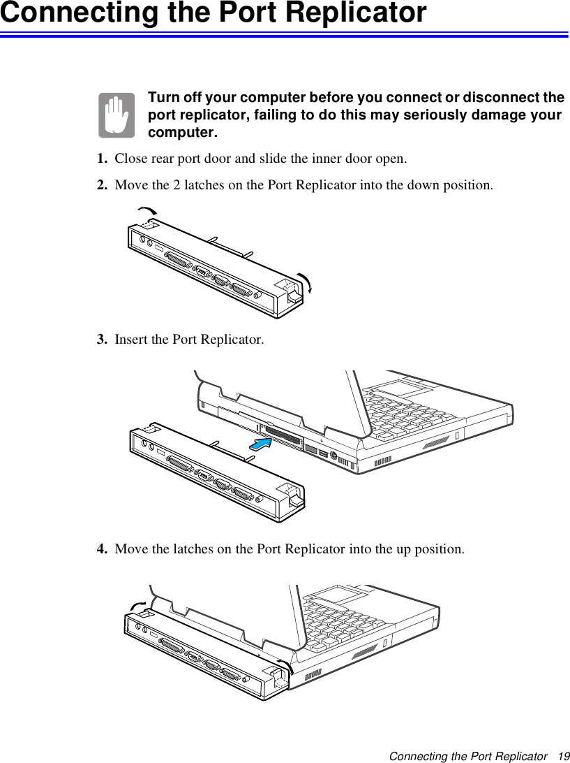
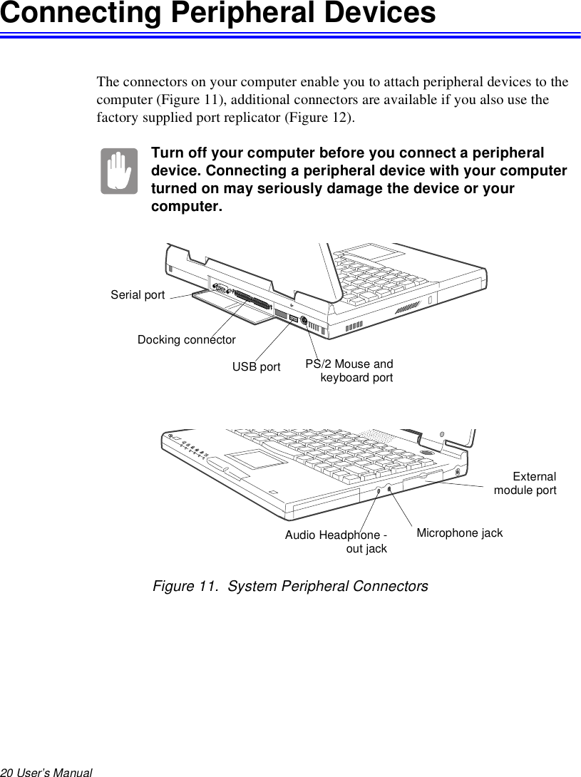
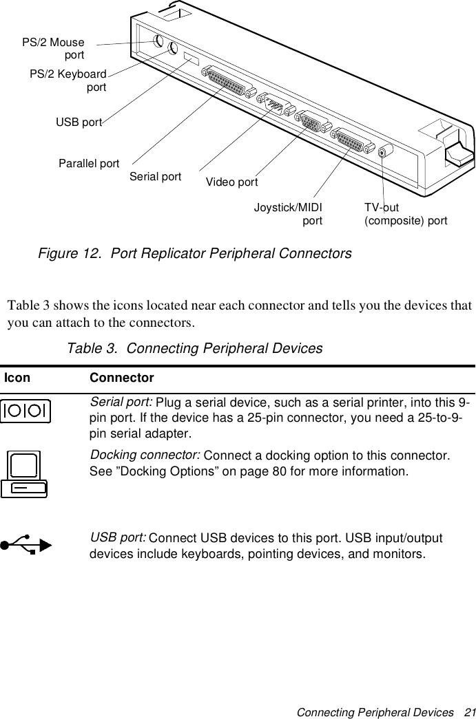
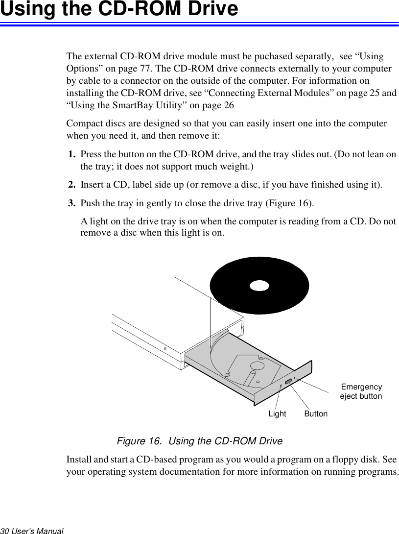
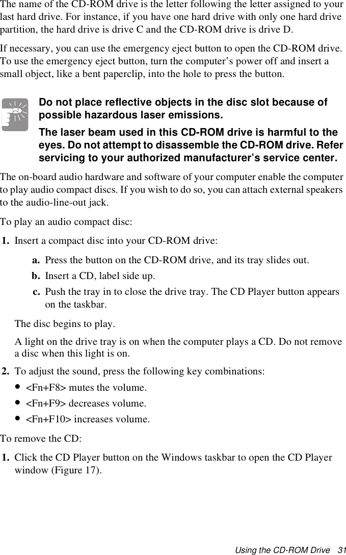

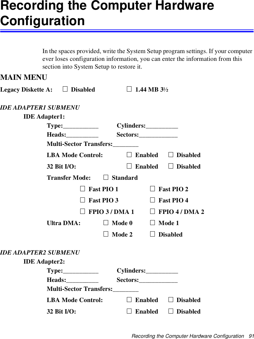
![66 User’s Manual 10. Click the Next button to install the new driver and follow any directions on the screen to finish setting the display properties.In Windows NT 4.0:1. As the computer starts, select Windows NT Workstation Version 4.00 [VGA mode] as the operating system and press <Enter>.2. Log on to the computer as supervisor. The Invalid Display Settings window appears.3. Click the OK button. The Display Properties window appears.If the Change Display window appears, go to step 6.4. Select the Settings menu.5. Click the Display Type button. The Display Type window appears.6. Click the Change button. The Change Display window appears.7. Click the Have disk button. If the driver is on a floppy disk insert it into the floppy drive or if you want to use the origianl factory driver insert the Utility CD-ROM into the CD-ROM drive. Click the Browse button and locate driver you want to install. Click the OK button.8. A line similar to the following line appears under the Display option: ATI Technologies Inc. 3D Rage LT Pro.9. Click OK. The Third-Party Driver window appears.10. Click Yes. The driver is copied. A window appears telling you the driver has been successfully copied.11. Click OK. Remove the disk from the floppy drive. Close the open windows on the screen.12. Click Yes when prompted to restart the computer. As the computer restarts, select Windows NT Workstation Version 4.00 as the operating system and press <Enter>.13. Log on as supervisor. The Invalid Display Settings window appears.14. Click the OK button. Click the Test button at the Display Properties window and follow any directions on the screen to finish setting the display properties.](https://usermanual.wiki/Samsung-Electronics-Co/S750E/User-Guide-18725-Page-75.png)