Samsung Electronics Co S750E Notebook Computer, 366MHz Pentium II User Manual manual
Samsung Electronics Co Ltd Notebook Computer, 366MHz Pentium II manual
manual

i User’s Manual
Notice
1998. All rights reserved
The information within this manual is subject to change without notice.
The manufacturer shall not be held liable for technical or editorial errors or
omissions contained in herein; nor for incidental or consequential damages
resulting from the furnishing, performance or use of this material.
No part of this publication may be reproduced, stored in a retrieval system, or
transmitted, in any form or by any means, mechanical photocopying, recording or
otherwise, without the prior written permission of the manufacturer.
Product names mentioned herein are for identification purposes only, and may be
trademarks and/or registered trademarks of their respective companies.
This product incorporates copyright protection technology that is protected by
method claims of certain U.S. patents and other intellectual property rights
owned by Macrovision Corporation and other rights owners.
Use of this copyright protection technology must by authorized by Macrovision
Corporation, and is intended for home and other limited viewing uses only unless
otherwise authorized by Macrovision Corporation. Reverse engineering or
disassembly is prohibited.

ii
Important Safety Instruction
Read all of these instructions, and save these instructions for later use.
•Follow all warnings and instructions marked on the product. Unplug this
product from the wall outlet before cleaning. Do not use liquid cleaners or
aerosol cleaners. Use a damp cloth for cleaning.
•Do not use this product near water. Never spill liquid of any kind on the
product.
•Do not place this product on an unstable cart, stand, or table.
•Slots and openings in the cabinet are provided for ventilation, to ensure
reliable operation of the product on a bed, sofa, rug, or other similar
surface. This product should never be placed near or over a radiator or
heat register. This product should not be placed in a built-in installation
unless proper ventilation is provided.
•Before connecting this product to a power source, check the required
voltage and frequency match the available power source.
•This computer is powered by an internal battery pack or by an external AC
power source through an external AC adapter. Use of another battery pack
or external AC adapter may present risk of fire or explosion.
•This product is equipped with a 2-wire type plug. If you are unable to insert
the plug into the outlet, contact your electrician to replace your obsolete
outlet.
•Do not allow anything to rest on the power cord.
•Do not place this product in a location where someone may trip over the
cord.
•If an extension cord is used with this product, make sure that the total of the
ampere ratings on the products plugged into the extension cord do not
exceed the extension cord ampere rating.
•Never push objects of any kind into this product through the cabinet slots,
as they may touch dangerous voltage points or short out parts; that could
result in a risk of fire or electric shock.
•Except as explained elsewhere in this manual, do not attempt to service this
product yourself.
•Handle battery, floppy and CD-ROM drives with care. If dropped, they
may be damaged.
•Do not allow the battery to be exposed to direct sunlight for extended
periods of time.

iii User’s Manual
•Do not attempt to disassemble the battery. If the battery is disassembled and
the electrodes are exposed to outside, the battery may generate heat and
smoke by chemical reaction.
•Do not expose the battery to moisture or chemicals.
•Charge the battery only as described in this document.
•Do not short circuit the battery terminals as the resulting high currents can
damage the battery.
•The battery should not be used to power other products.
•Do not dispose of a used battery in a fire or incinerator, as an explosion may
result.
•The battery should be recycled.
•Do not subject the battery to temperature less than -20 degrees Centigrade
or greater than 50 degrees Centigrade.
•Unplug this product from the wall outlet and refer problems to the service
representative under the following conditions:
- When the power cord or plug is damaged or frayed.
- If liquid has been spilled into product.
- If the product has been exposed to rain or water.
- If the product does not operate normally when the operating instruc-
tions are followed, adjust only those controls that are covered by
the operating Instructions. Improper adjustment of other controls
may result in damage.

iv
Battery Disposal
Warning : Do not put rechargeable batteries or products powered by non-
removable rechargeable batteries in the garbage.
Contact your customer service representative for information on how to dispose
of batteries that you cannot use or recharge any longer.
Follow all local regulations when old batteries.

v User’s Manual
Federal Communications Commission
(FCC)
This device complies with Part 15 of the FCC Rules. Operation is subject to the
following two conditions:(1) this device may not cause harmful interference, and
(2) this device must accept any interference received, including interference that
may cause undesired operation.
NOTE:
This equipment has been tested and found to comply with the limits for a Class B
digital device pursuant to Part 15 of the FCC Rules. These limits are designed to
provide reasonable protection against harmful interference in a residential
installation. This equipment generate uses and can radiate radio frequency energy
and if not installed and used in accordance with the instructions may cause
harmful interference will not occur in a particular installation. If this equipment
does cause harmful interference to radio or television reception, which can be
determined by turning the equipment off and on, the user is encouraged to try to
correct the interference by one or more of the following measures:
•Reorient or relocate the receiving antenna.
•Increase the separation between the equipment and receiver.
•Connect the equipment into an outlet on a circuit different from that to
which the receiver is connected.
•Consult the dealer or an experienced radio/TV technician for help.
If necessary, the user should consult the dealer or an experienced radio/television
technician for additional suggestions. The user may find the following booklet
helpful: "Something About Interference." This is available at FCC local regional
offices. Our company is not responsible for any radio or television interference
caused by unauthorized modifications of this equipment or the substitution or
attachment of connecting cables and equipment other than those specified by our
company. The correction will be the responsibility of the user. Use only shielded
data cables with this system.

vi
Canadian Radio Interference
Regulations
This apparatus does not exceed the class B limits for radio noise emissions set out
in the radio interference regulations of the Canadian Department of
Communications.
Le présent appareil n’émet pas de bruits radioélectriques dépassant les limites
applicable aux appareils de la classe B prescrites par le règlement de brouillage
radioélectrique dicté par le Ministère des Communictions du Canada.

vii User’s Manual
Table of Contents
Using Your Documentation .....................................................................1
This User’s Manual ..........................................................................................1
Special Features of the User’s Manual .............................................................1
Using the Software Documentation ..................................................................2
Introducing Your Computer ...................................................................3
Using Your Computer for the First Time ..............................................5
Attaching the AC Adapter ................................................................................5
Turning On the Computer ................................................................................6
Understanding POST ........................................................................................7
Adjusting the LCD Display ..............................................................................8
Turning Off Your Computer ............................................................................8
Restarting Your Computer ...............................................................................9
Tips for Using Your Computer .........................................................................9
Traveling with Your Computer ......................................................................10
Handling Spills ...............................................................................................11
Storing the Computer for Long Periods .........................................................11
Using the Keyboard ................................................................................12
Using the Numeric Keypad ............................................................................13
Using Special Function Keys .........................................................................14
Using the Touchpad ...............................................................................16
Reading the System Status Lights .........................................................17
Connecting the Port Replicator ............................................................19
Connecting Peripheral Devices .............................................................20
Using the TV-out (composite) Port ................................................................23
Connecting External Modules ...............................................................25
Using the SmartBay Utility ............................................................................26
Using the Floppy Drive ..........................................................................28
Using the CD-ROM Drive .....................................................................30
Using the Hard Drive .............................................................................33
Using the Battery ....................................................................................34
Charging the Battery .......................................................................................34
Safely Using the AC Adapter and Batteries ...................................................35
Removing and Inserting the Battery ...............................................................35

viii
Monitoring the Battery Charge .......................................................................37
Using the Battery Gauge ...........................................................................37
Using PowerProfiler to Monitor the Battery .............................................38
Battery Warnings ............................................................................................39
Using System Setup ................................................................................40
Starting System Setup .....................................................................................40
Main Menu .....................................................................................................42
Advanced Menu ..............................................................................................45
Security Menu ................................................................................................48
Power Menu ....................................................................................................49
Boot Menu ......................................................................................................51
Exit Menu .......................................................................................................51
Using System Security ............................................................................53
System Passwords ..........................................................................................53
Creating a Password .......................................................................................53
Deleting a Password .......................................................................................54
Requiring a Boot Password ............................................................................54
Locking the Hard Drive Boot Sector ..............................................................55
Locking the Floppy Drive ..............................................................................55
Locking the Keyboard ....................................................................................55
Using Power Management Options ......................................................56
Maximum Power Saving Mode ......................................................................56
Standby Mode .................................................................................................56
Rest Mode .......................................................................................................57
Rest Mode Precautions ...................................................................................58
Using PowerProfiler .......................................................................................58
Creating a Save to Disk Partition .........................................................60
Changing the Video Configuration .......................................................62
Resolution and Color Depth ...........................................................................62
Configuring Display Features .........................................................................63
Selecting a Monitor Type .........................................................................64
Changing Color Depth and Resolution .....................................................64
Changing the Video Driver ............................................................................65
In Windows 98: .........................................................................................65
In Windows NT 4.0: .................................................................................66
Working with PC Cards ........................................................................67
Maintaining PC Cards ....................................................................................67
Using PC Cards ..............................................................................................68

ix User’s Manual
Windows 98 ..............................................................................................69
Windows NT 4.0 .......................................................................................70
About Drivers and System Resources ..................................................72
Drivers ............................................................................................................72
IRQs ................................................................................................................72
Enabling the Infrared Port ..............................................................................73
Service Pack 3 for Windows NT 4.0 ..............................................................74
Troubleshooting ......................................................................................75
Operating Problems ........................................................................................75
Using Options ..........................................................................................77
AC Adapter .....................................................................................................77
Auto Adapter ..................................................................................................78
Battery Pack ....................................................................................................78
Memory Modules ...........................................................................................79
External Numeric Keypad ..............................................................................79
External CD-ROM Drive Module ..................................................................79
External DVD-ROM Drive Module ...............................................................80
Docking Options .............................................................................................80
Specifications ..........................................................................................81
Abbreviations ..........................................................................................83
Glossary ...................................................................................................86
Recording the Computer Hardware Configuration ...........................91

Using Your Documentation 1
Using Your Documentation
Congratulations on your purchase of a portable computer! Whether you are new to
using a portable computer or are an experienced user, your documentation can help
you get the most from your computer. Your computer comes with the following
documentation:
•The User’s Manual
•Third-party software user documentation
The following sections tell you where to look for the information you need.
This User’s Manual
This user’s manual can help you to
•Learn how to use your computer.
•Learn safety and maintenance tips.
•Learn how to configure your computer.
•Get answers to troubleshooting questions.
Special Features of the User’s Manual
Three types of messages with icons appear in the manual:
A note informs you of special circumstances.
A caution warns you of possible damage to equipment.
A warning indicates the possibility of personal injury.

2 User’s Manual
Keys that you need to press to perform certain functions are shown in the manual
enclosed in angle brackets. For example,
<Ctrl>
indicates the control key (Ctrl on the computer’s keyboard).
If you need to press two keys at the same time, the key names are shown joined by
a plus sign. For example,
<Fn+F11>
means that you should press the Fn key and hold it and then press the F11 key.
If you are new to using computers, see the Glossary. The Glossary explains general
computing terms that are used in this manual and tells you about some of the
differences between portable computers and desktop computers.
Using the Software Documentation
Your computer shipped from the factory with several software programs installed.
The software may include its own online or printed documentation. Refer to the
documentation or the Help options in the software for more information.
Introducing Your Computer 3
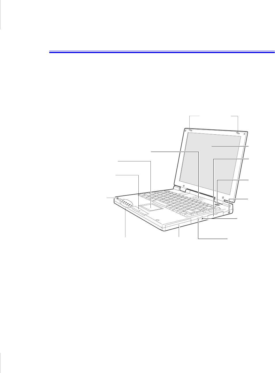
Introducing Your Computer
Your computer is an ultra-thin lightweight portable computer that includes
features to meet your computing needs at home or on the road. A port replicator is
supplied with each computer, see Figure 12 on page 21 for more information.
Figure 1 through 3 shows you the features of your computer.
Figure 1. Front View of Computer
LCD latchs
LCD
Power
button
AC adapter
connector
Battery
Touchpad
Microphone
Speaker
Status
lights
External
module
connector
Mouse
buttons
Microphone jack
Audio headphone
-out jack
4 User’s Manual
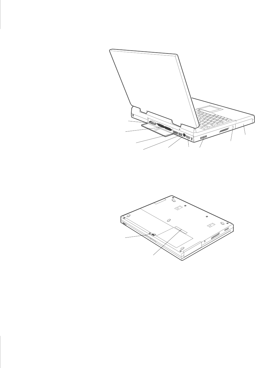
Figure 2. Back View of Computer
Figure 3. Bottom View of Computer
Infrared
port
Docking
connector
PS/2™ mouse
and
keyboard port
Serial port
USB port
PC Card
compartment
Fan vents Kensington
lock support
Battery latch
Labels showing
part number and
serial number

Using Your Computer for the First Time 5
Using Your Computer for the
First Time
This section gives you detailed information on using your computer for the first
time.
Attaching the AC Adapter
Your computer runs on power from the battery that came installed in the computer
or from an electrical outlet. The first time that you use your computer, fully charge
the battery by attaching the AC adapter to the computer and to an electrical outlet.
Your AC adapter can accept an input voltage of 100 to 120 V AC or 200 to 240 V
AC.
All batteries lose their charge if they sit unused for an
extended time period. When not used, the provided battery
can discharge fully in 2 to 3 months. The battery may have
discharged in the time it took for the computer to go from the
factory to you.
To attach the AC adapter:
1. Plug the AC adapter into the power connector on the right side of the computer
(Figure 4).
2. Connect the power cord to the AC adapter and then to an electrical outlet.
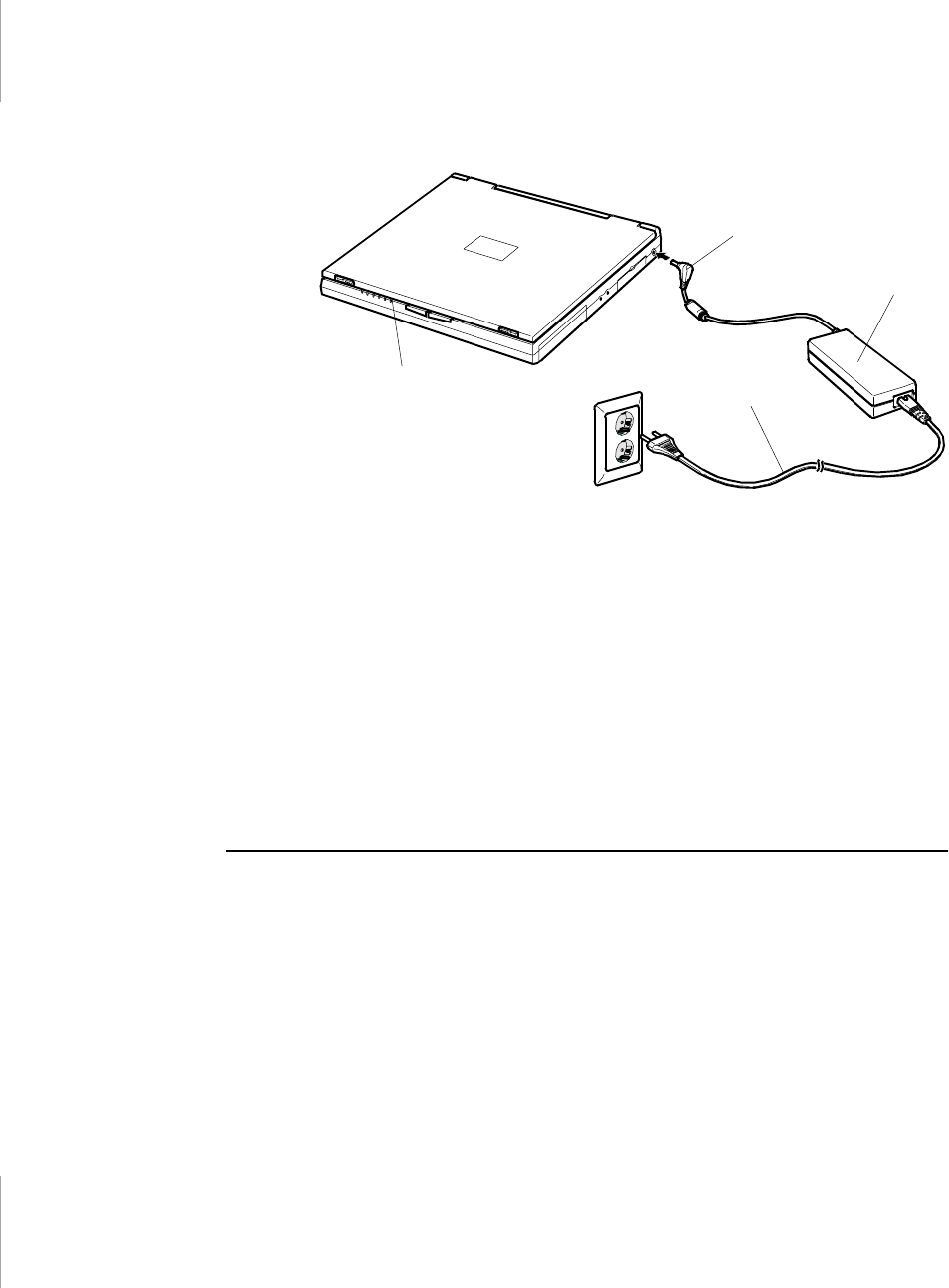
6 User’s Manual
Figure 4. Connecting the AC Adapter
The battery starts charging as soon as you plug the AC adapter into an electrical
outlet. The battery charges faster if the computer is turned off during charging.
If the battery is fully depleted and the computer is turned off, the battery charges
in about 2.5 hours. If the computer is turned on, the battery charges in about 4
hours. When the battery is charging, the battery charge light is amber. When the
battery is fully charged, the light turns green.
See ”Using the Battery” on page 34 for more information on using your
computer’s battery.
Turning On the Computer
To turn on the computer’s power for the first time:
1. Slide the LCD cover latches apart and hold them (Figure 5).
2. Lift up the LCD cover.
Adapter plug
AC adapter
Battery
charge
light
Power cord
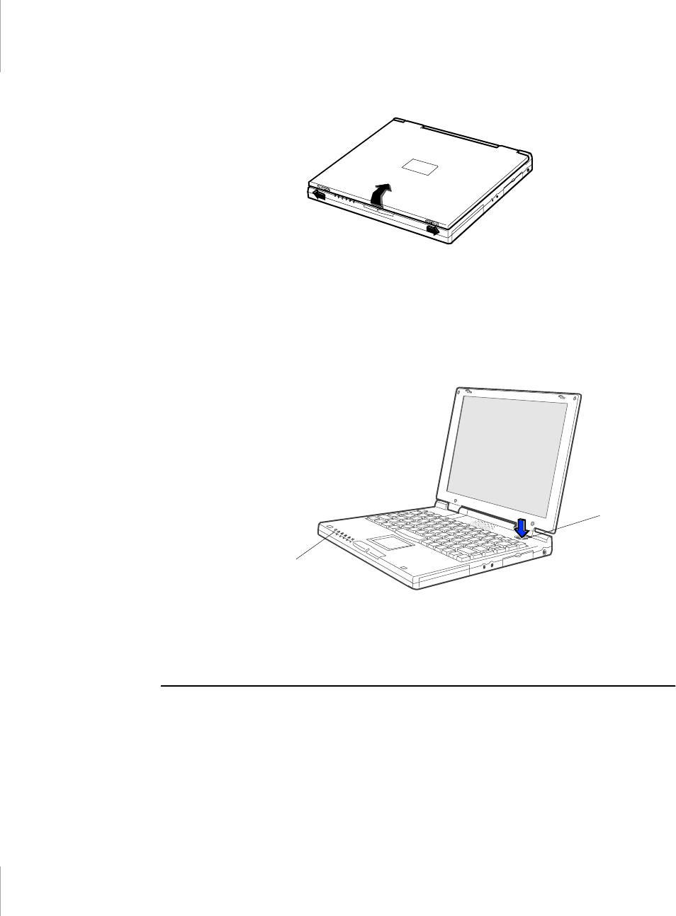
Using Your Computer for the First Time 7
Figure 5. Opening the Computer
3. Press and then release the power button (Figure 6).
The power light is on when the computer’s power is on.
Figure 6. Turning On the Computer’s Power
Understanding POST
When you turn on your computer, a routine called POST automatically runs to test
the computer components. The Manufacturer’s logo appears on the screen during
POST, if you press the ESC key while the logo is displayed you will see several
messages on the screen (see “Boot Menu” on page 51 for information on disabling
the logo screen).
Power light
Power button

8 User’s Manual
Screen messages are built into the computer to report both normal and abnormal
system conditions. If an error message appears, take any action suggested in the
message. If the message identifies the error condition but does not suggest any
corrective action, write down the message and contact the manufacturer or an
authorized manufacturer’s service center for assistance.
Adjusting the LCD Display
You may wish to adjust the LCD display when you begin using your computer. A
TFT LCD does not require adjustment for contrast because the contrast is set to
remain at maximum.
To adjust the brightness of the LCD:
•Press <Fn+Right Arrow> to increase the display brightness.
•Press <Fn+Left Arrow> to decrease the display brightness.
Turning Off Your Computer
If your computer has a Windows operating system, turn off
your computer by performing the shutdown procedure
described in this section. Otherwise, you may lose data.
To turn off the computer:
1. Click Start on the taskbar.
2. Click Shut Down.
3. Select the shut down option.
4. Click OK or Yes.
•If the operating system is Windows 98, the computer turns off.
•If the operating system is Windows NT, you receive a shutdown message
and must press the power button to turn off the computer.

Using Your Computer for the First Time 9
Restarting Your Computer
You may need to restart (reboot) your computer when installing hardware or
software or if the computer does not respond to your input. A warm (or soft) boot
prompts you to save your files, turns off the computer, and then restarts the
computer. A cold boot turns off the computer without saving your files.
Do not perform a cold boot unless your keyboard and
touchpad have no effect and you cannot perform a warm
boot.
When you perform a cold boot, you lose data unless it was
saved to a storage medium.
To perform a warm (or soft) boot:
1. Click the Start button on the taskbar.
2. Click Shut Down.
3. Select Restart the Computer.
4. Click the Yes button.
5. Save your files if prompted. Your computer reboots.
You can also perform a soft boot by saving your files and pressing <Ctrl+Alt+Del>
and then clicking on Shut Down.
You can perform a cold (or hard) boot by pressing the power button to turn the
computer off, waiting five seconds, and then pressing the power button to turn the
computer on.
Tips for Using Your Computer
The following information helps you avoid potential problems as you use your
computer:
Do not try to disassemble your computer. Opening the
system chassis voids your warranty. Only an authorized
manufacturer’s service center can replace or add any parts
inside the chassis.
•Follow all the instructions and cautions in your computer user documentation.

10 User’s Manual
•The LCD has a polarized surface and can be damaged easily. To prevent
damage, avoid touching the screen.
•Use only manufacturer approved AC adapters, automobile adapters and
memory modules.
•Because a portable computer is small and has restricted air flow around
components, it is more likely to overheat than a desktop computer. A fan
inside your computer helps to eliminate some heat. Make sure the fan vent on
the side of your computer is not blocked when you use the computer. (See
Figure 2 on page 4 for the location of the vent.) Occasionally check the vent
and remove any accumulated dust on the outside.
•Avoid using or storing the computer in extremely hot or cold areas, such as a
car on a hot day. Keep the computer away from heaters and out of direct
sunlight. Exposure to excessive heat may damage computer components.
•If you have left your computer in a hot place, let it cool down slowly to room
temperature (with the LCD panel open) before using it.
•Set up your computer work area to avoid physical strain. Sit with your back
straight and supported by your chair. Adjust your chair or work table so that
your arms and wrists can remain in a relaxed position, parallel with the floor.
Avoid bending or twisting your wrists as you work. Your hands should “float”
slightly above the keyboard. Refer to a book on office ergonomics for more
information on setting up your work area.
•Take frequent breaks from working at the computer to rest your eyes and
stretch your muscles.
•Remember to save your data files frequently and to make backup copies of
your files.
Traveling with Your Computer
If you are traveling by airplane, follow these tips:
•Take the computer with you as carry-on luggage. Do not check the computer
with your baggage.
•Allow the computer and disks to go through the X-ray security devices. Do
not hand-carry disks through the walk-through metal detectors, which can
cause loss of data.
•Make sure that the battery is charged or the AC adapter is easily accessible.
You may be required to turn on the computer for airport security personnel.
•Be prepared to turn off the computer during take off and landing.

Using Your Computer for the First Time 11
Handling Spills
Do not spill anything on your computer. The best way to avoid spills is to avoid
eating and drinking around your computer. If you do spill something on your
computer, turn off your computer, unplug it immediately, and do the following:
•If you spill liquid on the internal keyboard or any external devices (such as the
floppy drive), drain as much of the liquid as possible. Be careful not to let the
liquid drip onto the LCD panel. Allow the system to dry for several days
before trying to use it.
•If you spill liquid on an external keyboard or keypad, unplug it and drain as
much of the liquid as possible. Allow the keyboard to sit at room temperature
for a full day before trying to use it.
Sweet liquids leave a sticky residue that may cause damage
despite your efforts to dry.
•If you spill liquid on the LCD panel, clean it immediately with a soft cloth and
denatured alcohol. Do not use water, window cleaner, acetone, aromatic
solvent, or dry, rough towels to clean it.
Some liquids damage the polarized LCD screen. If your
screen is damaged, contact your authorized manufacturer’s
service center for a replacement.
Storing the Computer for Long Periods
If possible, leave the AC adapter connected to the computer when the computer is
not in use. This helps extend the life of the battery and keeps the battery fully
charged.
If you will not be using the computer for an extended period of time (a month or
more), you should charge the battery until it is completely full. After you have
done so, remove the battery from the unit.
12 User’s Manual
Using the Keyboard
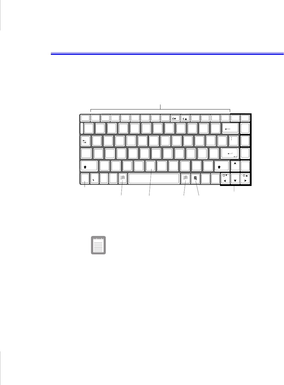
Your computer has an 87/88-key keyboard (Figure 7). By pressing designated key
combinations, you can have access to all the key functions of a full-sized keyboard.
Figure 7. Keyboard
Although the layout of the keys on your computer’s keyboard
is different from that on a desktop computer’s keyboard, the
keyboard feels like a full-sized keyboard when you use it. The
distance between the keys (the pitch) is the same as on a full-
size keyboard (19 mm). The travel, or space the key goes
down when pressed, is (2.5 mm).
The keys on the keyboard can be grouped into the following categories:
•Full-sized typewriter keys are arranged like a standard typewriter keyboard
and are used for text entry.
•Function keys, when pressed together with the <Fn> key, enable special
functions.
~
F1 F2 F3 F4 Insert DeletePause
Esc BreakSys Req
End
Home
CtrlCt
~AltAlt
Enter
BackSpace
Caps
Lock
0./
,.
>< /
?
ZXCVBNM
Fn
Shift Shift
+"
'
123
ASDFGHJKL;
:
-
{
[
{
[
45 6
QWERT YUI OP
Tab
!#$
134
PgUp
/
PgDn
F5 F6 F8 F9 F10 F11 F12 Num
Lock
ScrollRestMute
%^*
&()
56 7890+
=
_
-
789*
@
2
PrtScr GaugeCRT/LCDBacklit F7
KeyLock
Function keys
Windows
key
Cursor-control keys
Typewriter
keys
Windows keys
<Fn> key
Using the Keyboard 13
•Cursor control keys move the cursor. They may perform other functions,
depending on your software.
•Windows keys open Windows menus and perform other special functions.
To clean the computer keyboard, use slightly damp cotton swabs. Scrub the keys
and the surface around the keys. Do not allow liquid to drip into the keyboard or
you may damage the keyboard.
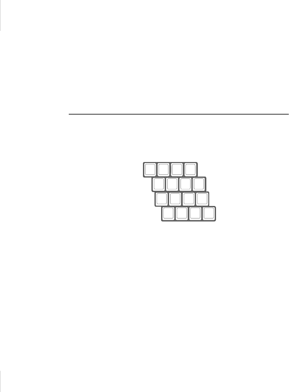
Using the Numeric Keypad
Your keyboard includes a numeric keypad, which is a group of keys that you can
set to type numbers and mathematical symbols, such as the plus sign (Figure 8). A
number or symbol on the right corner of each keypad key shows its numeric
function.
Figure 8. Numeric Keypad
Press <Num Lock> to turn on the embedded numeric keypad. The numeric
functions of the keypad are enabled and the Num Lock light turns on.
While the numeric functions are enabled, you can temporarily return a key to its
normal function by pressing <Fn> and the key. For example to type the letter m,
press <Fn+m>.
To turn the numeric keypad off, press <Num Lock> again. The Num Lock light
turns off.
0./
,.
>
</
?
M
+
123
JKL;
:
-
45 6
UI OP
*
&()
7890
789*

14 User’s Manual
Using Special Function Keys
The <Fn> key activates special functions when it is pressed in combination with
another key. Table 1 shows the special key combinations.
Table 1. Description of Special Function Keys
<Fn> Key
Combination Function
<Fn+F1>
Print screen:
In Windows 98 or Windows NT, takes a picture of
the open screen and puts it on the clipboard.
<Fn+F2>
System request:
Reserved for use in software programs.
<Fn+F4>
Backlight
: Turns the LCD display off. Press any key (except the
<Fn> key) to turn the LCD display back on.
<Fn+F5>
CRT/LCD:
Switches the display between the LCD, the external
monitor, and simultaneous display on both the LCD and the
external monitor.
<Fn+F6>
Gauge:
Displays the battery gauge in the upper-right corner of
your screen.
The gauge closes in a few seconds or by pressing <Esc> key.
(See ”Monitoring the Battery Charge” on page 37 for more
information on the battery gauge.)
<Fn+F7>
KeyLock:
Locks the keyboard and activates password protection.
Type the user or supervisor password and press <Enter> to
unlock the keyboard. If the supervisor password was entered on
boot only the supervisor password will unlock the system. The
<Fn+F7> key combination has no effect unless a password is
enabled in System Setup. The Num Lock, Caps Lock, and Scroll
Lock lights blink in sequence when the keyboard is locked.
<Fn+F8>
Mute:
Turns the audio output on and off.
<Fn+F9>
Volume down:
Decreases the audio volume.
<Fn+F10>
Volume up:
Increases the audio volume.
<Fn+F11>
Rest:
Puts the computer into rest or suspend mode. To resume
normal operation from rest, press the power button. (See ”Power
Menu” on page 49 for more information about the rest mode.)
<Fn+F12>
Scroll:
In some applications, sets the cursor-control keys to scroll
the page up or down while the cursor position does not change.
Pressing <Fn+F12> again turns off the scrolling function.

Using the Keyboard 15
<Fn+Right
Arrow>
Brightness up:
Increases the LCD brightness.
<Fn+Left
Arrow>
Brightness down:
Decreases the LCD brightness.
16 User’s Manual
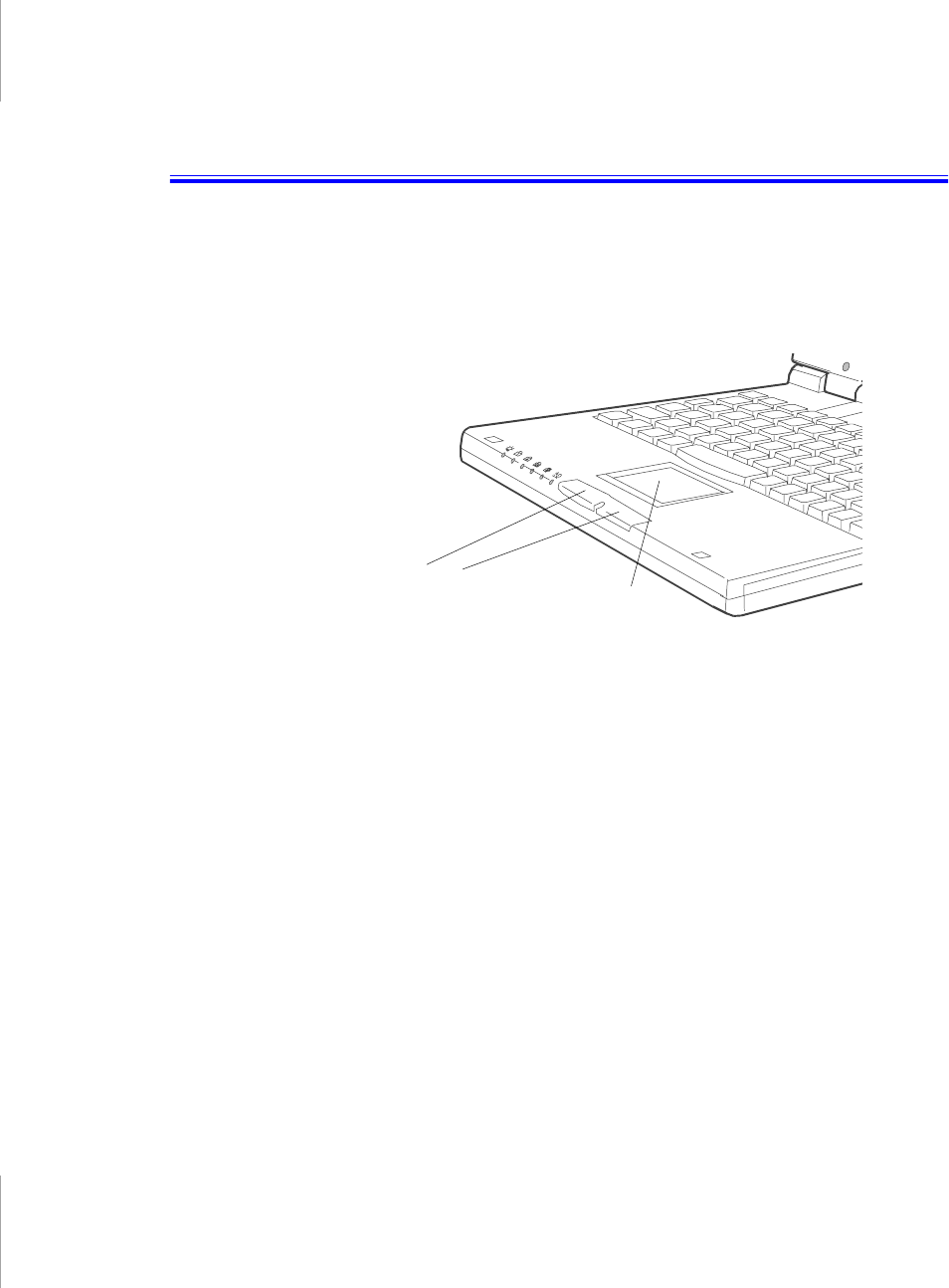
Using the Touchpad
Your computer is equipped with the SmartPoint™ touchpad, which is an
integrated-pointing device that is used to perform standard mouse functions
(Figure 9). The touchpad is an advanced and reliable pointing device that works
with a touch of your finger.
Figure 9. Touchpad
To use the touchpad:
•Place your finger on the pad and move your finger in the direction you want
the cursor to move. The faster you move your finger, the faster the cursor
moves across the screen.
•Roll your finger from side to side to move the cursor short distances.
•Quickly tap your finger on the touchpad to click an item.
•Tap your finger twice to double-click an item.
•Tap and drag your finger on the touchpad to click and drag an item.
•Press on the touchpad gently. The touchpad responds to light pressure.
You can also use the buttons at the bottom of the touchpad in the same way you
use standard mouse buttons.
For information on attaching and using another pointing device or keyboard with
your computer, “Connecting Peripheral Devices” on page 20
Touchpad
Mouse buttons
Reading the System Status Lights 17
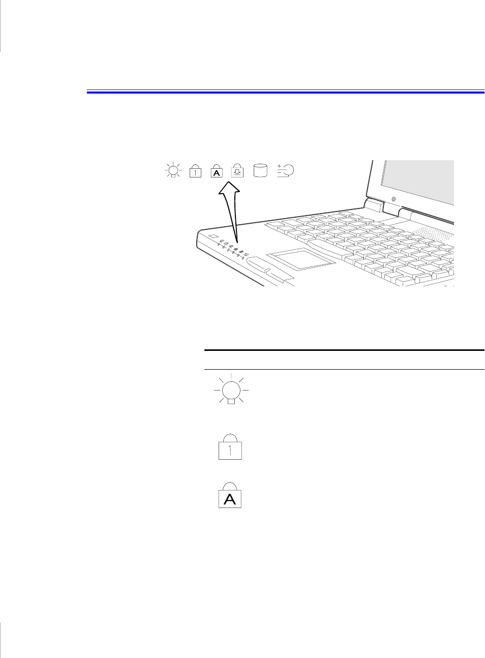
Reading the System Status Lights
System Status lights show the status of computer functions. The lights appear on
the left edge of the computer (Figure 10).
Figure 10. System Status Lights
Table 2 describes the meaning of the lights.
Table 2. System Status Lights
Icon Function of Light
Power light:
Light is on when the computer’s power is
on. The light blinks between green and amber when
the battery is low. The light changes to amber when
the system is power-on-suspend mode. The power
light is off if the system is turned off or is in rest mode.
Num Lock light:
Light is on when the embedded
numeric keypad is activated. See ”Using the Numeric
Keypad” on page 13 for a description of the keypad.
Caps Lock light:
Light is on when the caps lock
function is activated. When the function is activated, all
alphabetic characters you type will be in upper case.

18 User’s Manual
Scroll Lock light:
Light is on when the scroll lock
function is activated. The scroll lock function affects
cursor movement and text scrolling in some
applications. This is a software specific key. Refer to
the appropriate software manuals for a description of
the <Scroll> key.
Drive light:
Light is green when the hard drive is being
accessed. Do not turn your computer off when this light
is on. For a floppy or CD-ROM drive, check the light on
the drive itself to see if the drive is being accessed.
Battery charge light:
Light gives information about the
battery charge when the AC adapter is connected.
When the battery is charging, the light is amber. When
the battery is fully charged, the light turns green.
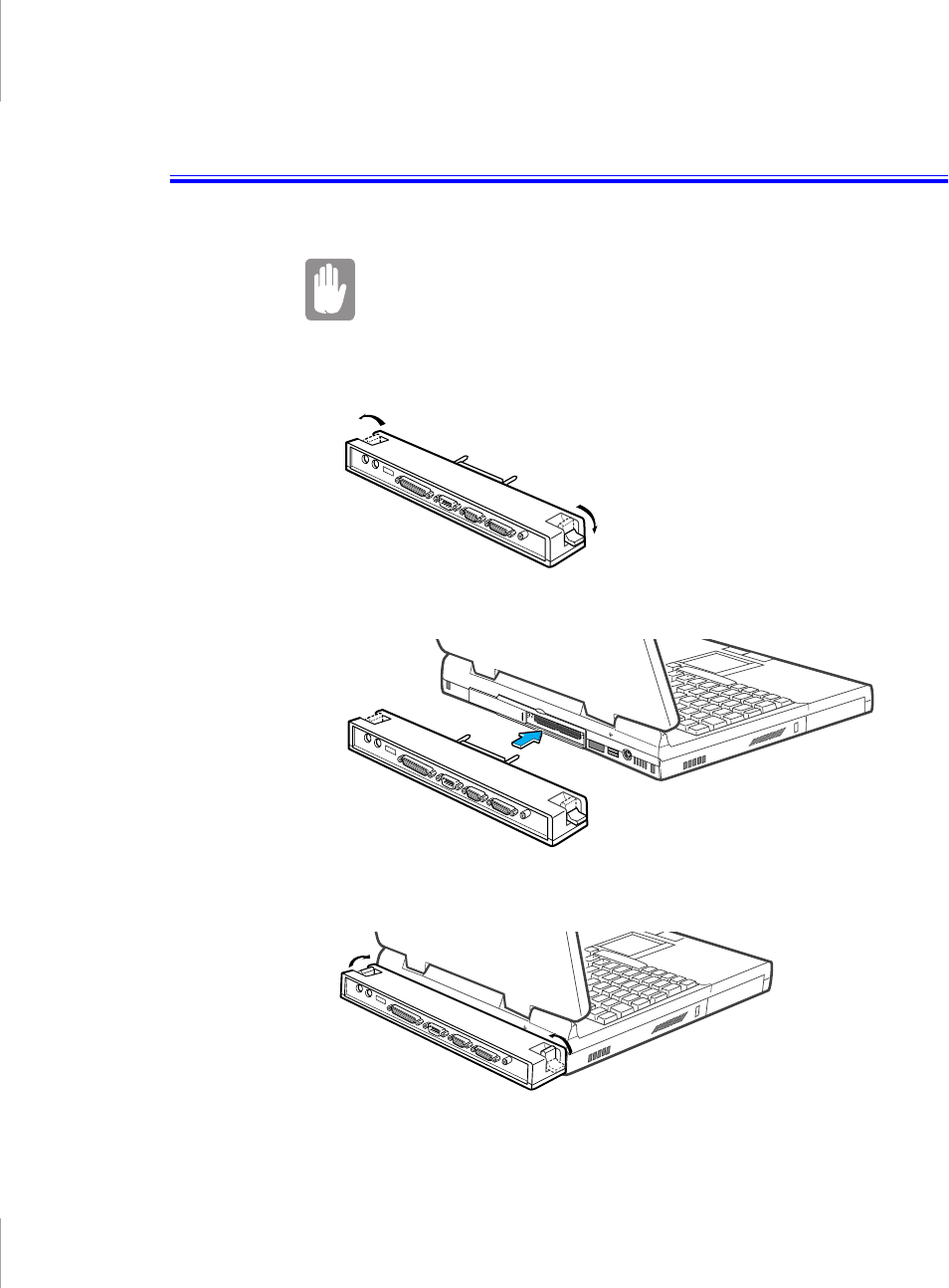
Connecting the Port Replicator 19
Connecting the Port Replicator
Turn off your computer before you connect or disconnect the
port replicator, failing to do this may seriously damage your
computer.
1. Close rear port door and slide the inner door open.
2. Move the 2 latches on the Port Replicator into the down position.
3. Insert the Port Replicator.
4. Move the latches on the Port Replicator into the up position.
20 User’s Manual
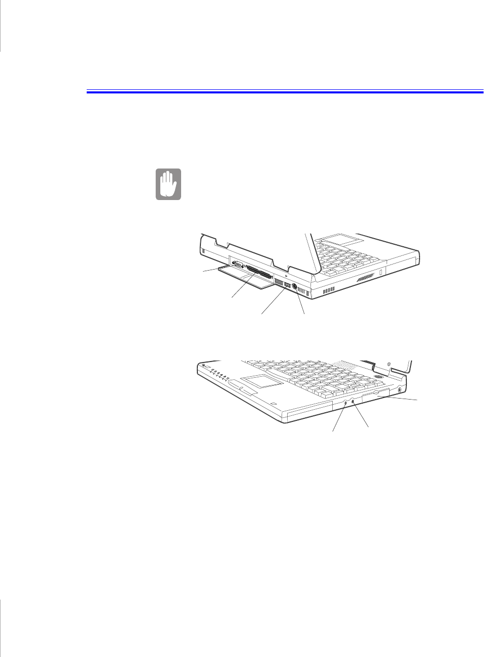
Connecting Peripheral Devices
The connectors on your computer enable you to attach peripheral devices to the
computer (Figure 11), additional connectors are available if you also use the
factory supplied port replicator (Figure 12).
Turn off your computer before you connect a peripheral
device. Connecting a peripheral device with your computer
turned on may seriously damage the device or your
computer.
Figure 11. System Peripheral Connectors
Microphone jack
Audio Headphone -
out jack
PS/2 Mouse and
keyboard port
Docking connector
Serial port
External
module port
USB port
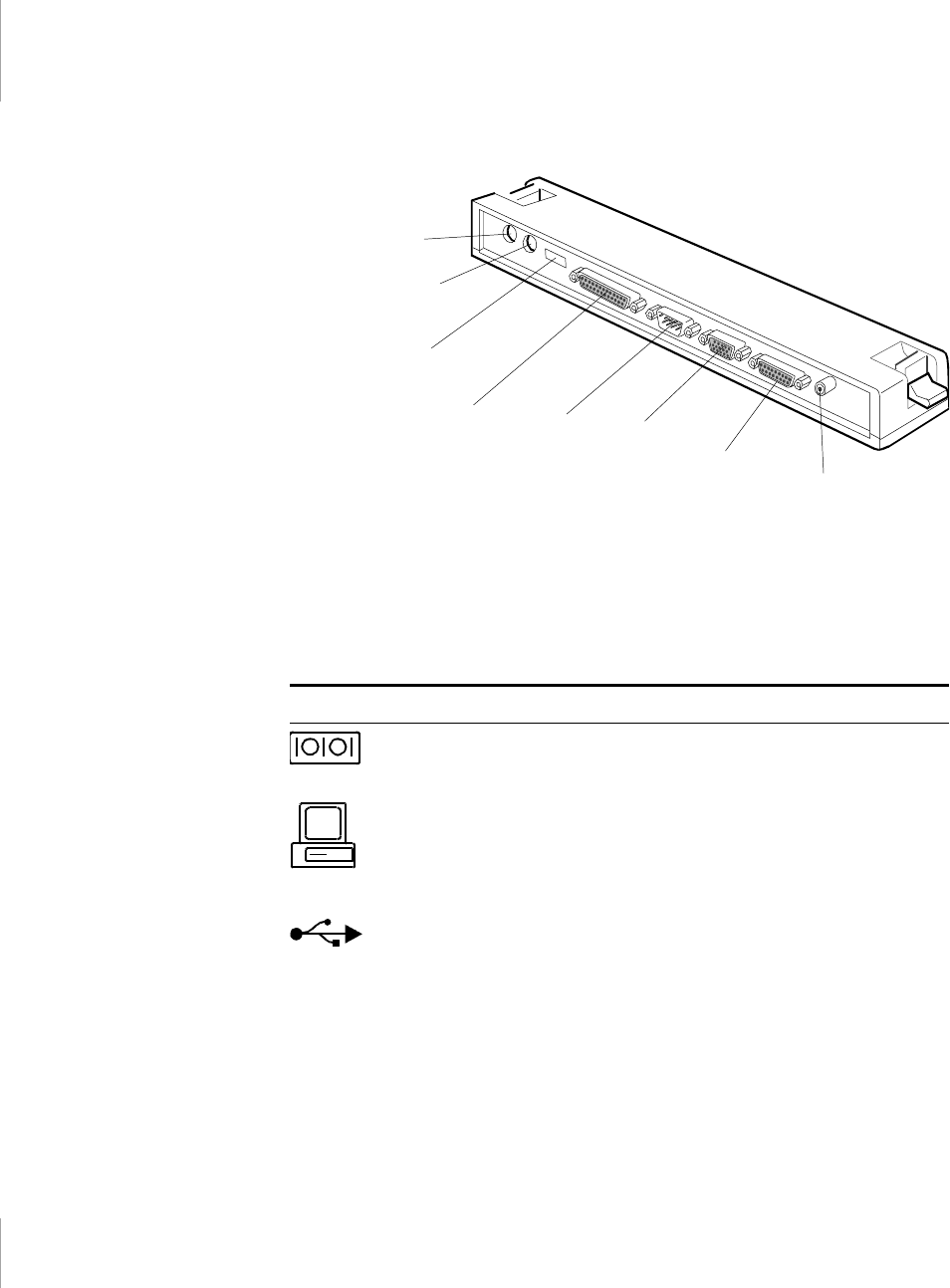
Connecting Peripheral Devices 21
Figure 12. Port Replicator Peripheral Connectors
Table 3 shows the icons located near each connector and tells you the devices that
you can attach to the connectors.
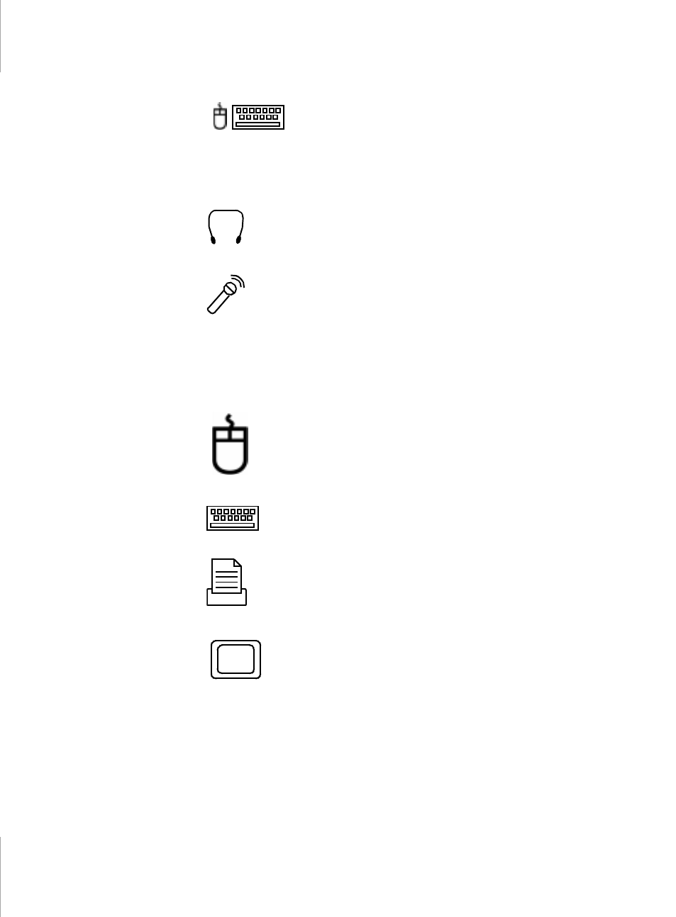
Table 3. Connecting Peripheral Devices
Icon Connector
Serial port:
Plug a serial device, such as a serial printer, into this 9-
pin port. If the device has a 25-pin connector, you need a 25-to-9-
pin serial adapter.
Docking connector:
Connect a docking option to this connector.
See ”Docking Options” on page 80 for more information.
USB port:
Connect USB devices to this port. USB input/output
devices include keyboards, pointing devices, and monitors.
PS/2 Mouse
port
Serial port
USB port
PS/2 Keyboard
port
Video port
Parallel port
Joystick/MIDI
port TV-out
(composite) port
22 User’s Manual
PS/2 mouse and keyboard port:
Connect a PS/2-compatible
mouse or external keyboard or keypad to this port. Make sure your
computer is turned off when you attach peripherals to the port.
You can use the computer’s touchpad and a PS/2 keyboard at the
same time. If you attach a PS/2 mouse to the port, the computer’s
touchpad may be disabled.
Audio headphone-out jack:
Connect stereo headphones or
speakers to this jack. Speakers connected to this jack override the
onboard speakers.
Microphone jack:
Connect an external microphone to this jack.
External module port:
Connect one end of the external module
cable to this connector and the other end to the external module.
See ”Connecting External Modules” on page 25 for more
information.
Mouse port:
Connect a PS/2-compatible mouse to this port. Make
sure your computer is turned off when you attach peripherals to the
port.
If you attach a PS/2 mouse to the port, the computer’s touchpad
may be disabled.
Keyboard port:
Connect an external keyboard or keypad to this
port. Make sure your computer is turned off when you attach
peripherals to the port.
Parallel port:
Plug a parallel device, such as a parallel printer or
network adapter, into this 25-pin port.
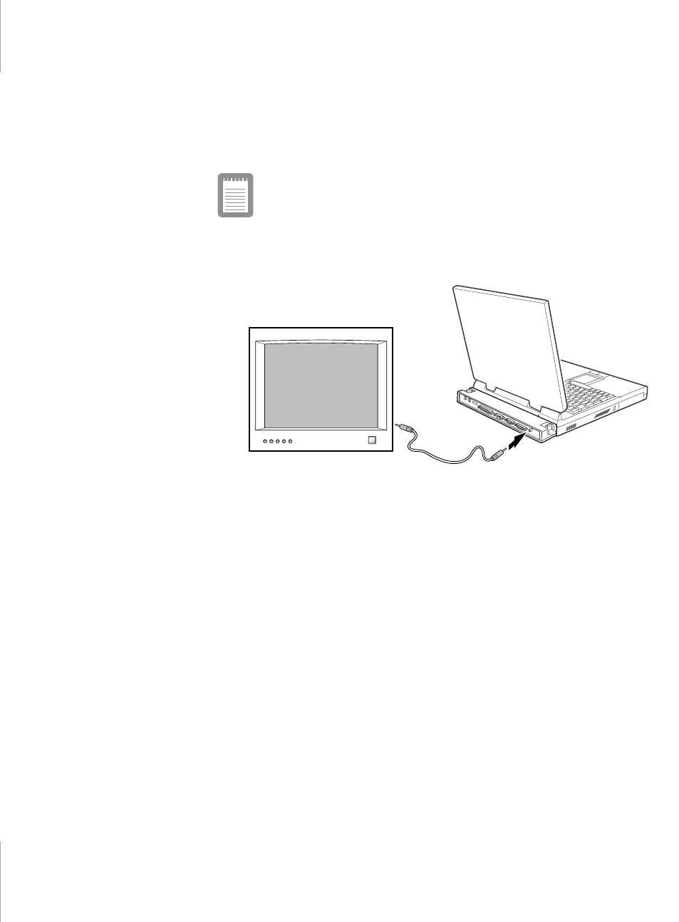
Video port:
Plug the interface cable of an external monitor into this
15-pin connector and then plug the monitor power cord into a
grounded outlet.

Connecting Peripheral Devices 23
Using the TV-out (composite) Port
This feature is only available with Windows 98. Using the TV-out (composite)
port on the port replicator, a compatible TV or other compatible display device can
be connected and an image displayed. To check if and how your TV displays the
TV-out (composite) signal see the documentation included with your TV.
You cannot enable TV Out display unless the current screen
resolution is lower than 1024x768, See ”Resolution and Color
Depth” for information on changing your screen resolution.
To enable TV-out:
1. Enter System Setup and under the Advanced menu, set TV Standard to the
appropriate standard for your TV. (See ”Using System Setup” on page 40 for
information on setting options.)
2. Reboot your computer.
3. Connect the TV to the TV-Out (composite) port using an appropriate cable,
Figure 13 on page 24
4. Click the Start button on the Windows 98 taskbar.
5. Select Settings.
6. Click Control Panel. The Control Panel window appears.
7. Double-click the Display icon. The Display Properties window appears.
8. Click the Settings tab. The Settings screen appears.
9. Click the Advanced Properties button. The Advanced Properties screen
appears.
Joystick/MIDI port:
Connect a joystick or other game pointing
device to this port. You can also connect a MIDI device to this port.
TV-out (composite) port:
Plug an RCA or Phono plug connector
from this port into an external monitor to get video only. No audio is
transmitted via this port. You cannot enable TV Out display unless
the current screen resolution is lower than 1024x768.
24 User’s Manual
10. Click the Displays tab. The system will now try to detect a TV connected to the
TV-out (composite) port.
11. Put a tick in the box under the TV symbol
If the TV symbol is grayed out then the system has not
detected a TV, check that the TV standard in the BIOS is set
correctly and that the TV is connected properly.
12. Click OK and follow the prompts that appear on the screen.
Figure 13. Attaching a TV to the TV-out (composite) port
Connecting External Modules 25
Connecting External Modules
This computer ship from the factory with an external floppy drive module. For
information about the optional CD-ROM and DVD-ROM drives, see “Using
Options” on page 77. These devices are connected to the computer’s external
module port using the external module cable.
If your operating system is Windows 98 you can use the
SmartBay utility to hot-swap the external modules. If you do
not use Windows 98, make sure that the computer’s power is
off before you remove or install any external modules.
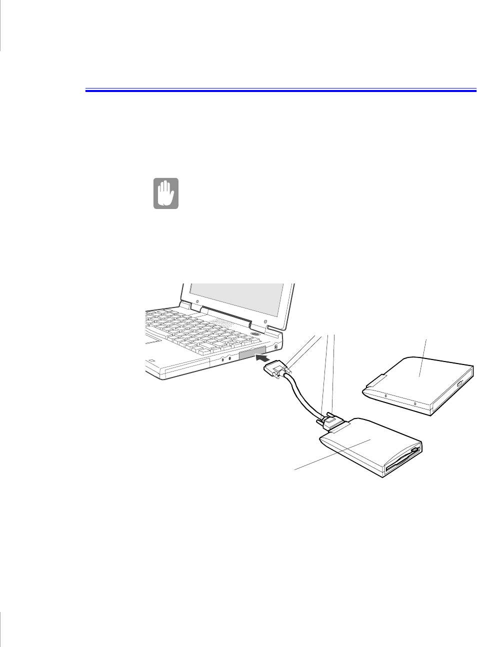
Only one external module can be used at any one time. Attach one end of the
external module cable to the module and the other to the external module port on
the computer (Figure 14).
Figure 14. Attaching the External Modules to the Computer
The external module cable must be inserted as shown in Figure 14. To insert the
cable correctly, make sure that
•The cable connector labeled System is connected to the Computer.
Thumb
screws CD-ROM drive
Floppy drive

26 User’s Manual
•The cable connector labeled Unit is connected to the external module.
•Secure the cable by tightening the thumbscrews.
Your computer’s operating system automatically recognises the device in the
SmartBay and configures your computer accordingly.
If the cable does not fit easily, do not force it. Make sure you
have the correct end of the cable going to the computer and
to the external module.
To remove the cable:
1. Loosen the thumbscrews
2. Pull the cable connectors away from the external module and the computer.
Using the SmartBay Utility
If your computer shipped with Windows 98, you can use the SmartBay utility to
hot-swap your external modules.
To open the SmartBay utility
1. Double click SmartBay Hotswap Utility on the Windows.
To remove an external module:
1. Open the SmartBay Hotswap Utility.
2. Select Remove Device and click Ok.
3. Click Yes on the confirmation screen
4. Remove the external module by either disconnecting the cable from the
computer or from the external module.
5. Click Ok.
To insert an external module:
1. Open the SmartBay Hotswap Utility.
2. Select Insert Device and click Ok.
3. Connect the external module to the computer using the external module cable.
Make sure all connectors are correctly attached.
4. Click Ok to allow your computer to detect the external module.

Connecting External Modules 27
If you have difficulty in getting an external module detected, go through the
remove procedure and then the insert procedure again.
28 User’s Manual
Using the Floppy Drive
The computer comes with an external 1.44-MB, 3.5-inch, high-density floppy
drive, which can read, write to, and format the following disks:
•A high-density, 3.5-inch disk, which stores 1.44 MB of data.
•A double-density, 3.5-inch disk, which stores 720 KB of data.
The floppy drive in your portable computer is smaller but
more power-efficient than a floppy drive in a desktop
computer. To get the best performance from your floppy
drive, handle the drive carefully when installing or removing
it and use high-quality floppy disks.
The floppy drive connects externally to your computer by cable to a connector on
the outside of the computer. For information on installing the floppy drive, see
“Connecting External Modules” on page 25 and “Using the SmartBay Utility” on
page 26
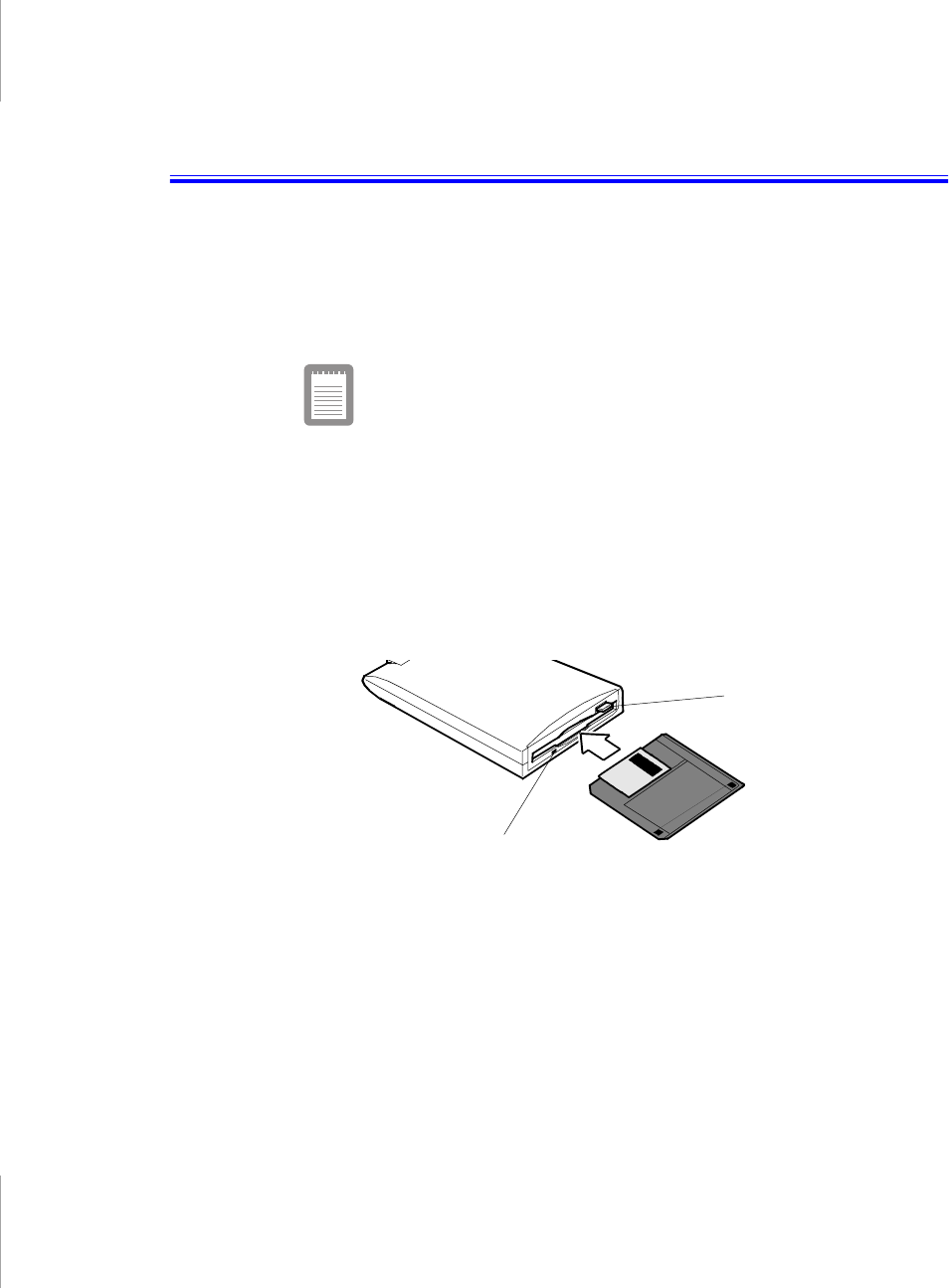
To use a floppy disk, insert it into the floppy drive (Figure 15).
Figure 15. Inserting a Floppy Disk
To remove a floppy disk, press the eject button on the floppy drive.
The drive light on the floppy drive is green when the computer writes to or reads
from a floppy disk. Do not remove a disk when this light is on.
To protect the data on your floppy disks, follow these guidelines:
•Keep disks away from excessive heat, direct sunlight, and liquids.
Floppy eject
button
Drive light

Using the Floppy Drive 29
•Keep magnets and any device that contains a magnet (like the telephone)
away from your disks.
Magnetic fields can destroy the information on a disk.
•Do not write directly on a label on your disk; instead, write on a disk label first
and attach the label to the disk.
•Make copies of all your important disks.
30 User’s Manual
Using the CD-ROM Drive
The external CD-ROM drive module must be puchased separatly, see “Using
Options” on page 77. The CD-ROM drive connects externally to your computer
by cable to a connector on the outside of the computer. For information on
installing the CD-ROM drive, see “Connecting External Modules” on page 25 and
“Using the SmartBay Utility” on page 26
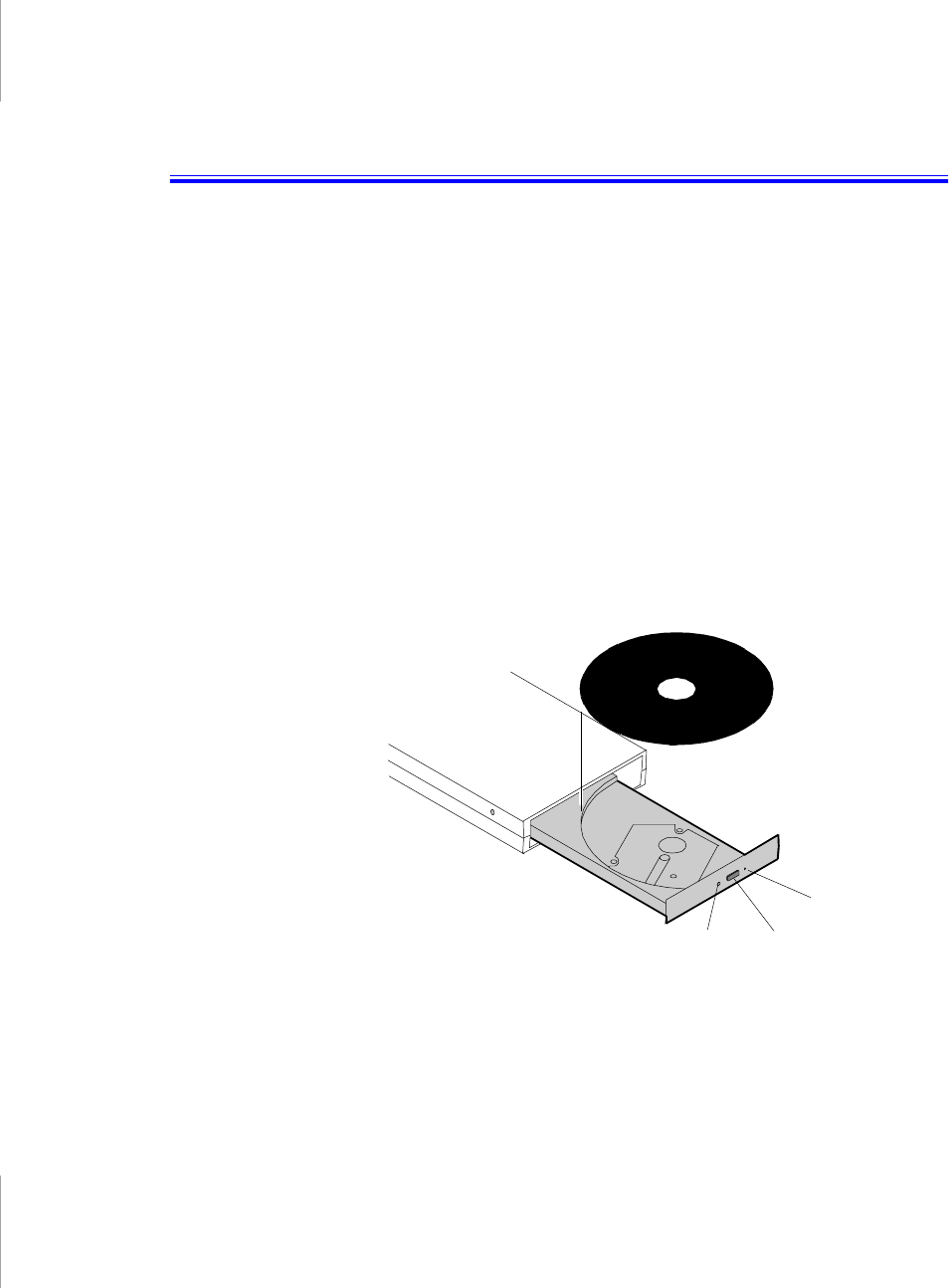
Compact discs are designed so that you can easily insert one into the computer
when you need it, and then remove it:
1. Press the button on the CD-ROM drive, and the tray slides out. (Do not lean on
the tray; it does not support much weight.)
2. Insert a CD, label side up (or remove a disc, if you have finished using it).
3. Push the tray in gently to close the drive tray (Figure 16).
A light on the drive tray is on when the computer is reading from a CD. Do not
remove a disc when this light is on.
Figure 16. Using the CD-ROM Drive
Install and start a CD-based program as you would a program on a floppy disk. See
your operating system documentation for more information on running programs.
ButtonLight
Emergency
eject button

Using the CD-ROM Drive 31
The name of the CD-ROM drive is the letter following the letter assigned to your
last hard drive. For instance, if you have one hard drive with only one hard drive
partition, the hard drive is drive C and the CD-ROM drive is drive D.
If necessary, you can use the emergency eject button to open the CD-ROM drive.
To use the emergency eject button, turn the computer’s power off and insert a
small object, like a bent paperclip, into the hole to press the button.
Do not place reflective objects in the disc slot because of
possible hazardous laser emissions.
The laser beam used in this CD-ROM drive is harmful to the
eyes. Do not attempt to disassemble the CD-ROM drive. Refer
servicing to your authorized manufacturer’s service center.
The on-board audio hardware and software of your computer enable the computer
to play audio compact discs. If you wish to do so, you can attach external speakers
to the audio-line-out jack.
To play an audio compact disc:
1. Insert a compact disc into your CD-ROM drive:
a. Press the button on the CD-ROM drive, and its tray slides out.
b. Insert a CD, label side up.
c. Push the tray in to close the drive tray. The CD Player button appears
on the taskbar.
The disc begins to play.
A light on the drive tray is on when the computer plays a CD. Do not remove
a disc when this light is on.
2. To adjust the sound, press the following key combinations:
•<Fn+F8> mutes the volume.
•<Fn+F9> decreases volume.
•<Fn+F10> increases volume.
To remove the CD:
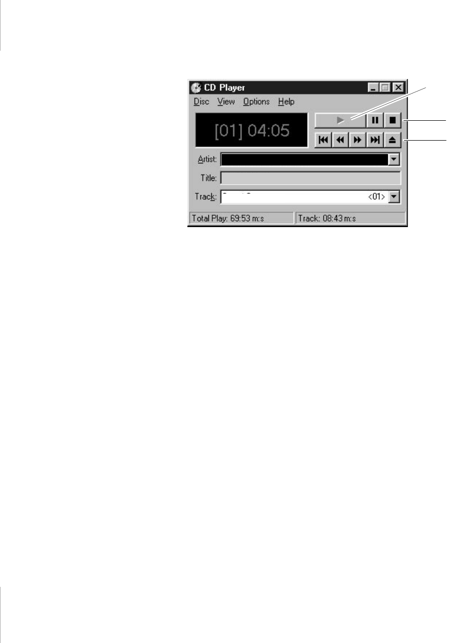
1. Click the CD Player button on the Windows taskbar to open the CD Player
window (Figure 17).
32 User’s Manual
Figure 17. CD Player Window
2. Click the Stop button in the CD Player Window.
3. Click the Eject button on the CD Player window or press the button on your
CD-ROM drive. The drive tray opens and you can remove the disc from the
CD-ROM drive.
For more information on playing compact discs, see the Help menu in the CD
Player window.
New Artist
New Title
Track 1
<D:>
Play
Stop
Eject

Using the Hard Drive 33
Using the Hard Drive
Your computer includes an IDE hard drive. The IDE hard drive can store the data
and programs your computer uses.
Although the storage capacity of hard drives varies according to model, any hard
drive holds much more than a floppy disk does. Also, the computer reads and
works with a hard drive more rapidly than with a floppy disk.
Once information is saved on a hard drive, it remains there until it is overwritten.
The hard drive heads park automatically when you turn off your computer.
The hard drive that comes with your computer has already
been formatted. Do not format the hard drive. Doing so
destroys all data contained on the drive. If you need to format
or erase all data on your hard drive, refer to the manual for
your operating system.
The drive in your computer is divided into partitions. Each partition is 2 GB or less
so that the partitions can use a 16-bit file allocation table (FAT-16). The file
allocation table enables the partitions to locate files and directories.Your computer
recognizes each partition as a separate drive, for example, if a hard drive has two
partitions, they could be recognized as drive C and drive D.
Although Windows 98 can work with FAT-16 or FAT-32 (a 32-bit file allocation
table), your computer has been supplied with FAT-16 as there are software
compatibility issues with FAT-32. Older software that you may have (16-bit
software) may require FAT-16 to run. Similarly Windows NT 4.0 can use FAT-16
or NTFS (the Windows NT file system). There are utilities included with Windows
98 and Windows NT 4.0 to convert from FAT-16 to FAT-32 or NTFS, see the
documentation included with your operating system for more information.
It is not possible to convert from FAT-32 or NTFS to FAT-16
without reformatting your hard drive.

34 User’s Manual
Using the Battery
Your computer uses a smart rechargeable lithium-ion battery pack for power when
the AC adapter is not attached to an electrical outlet. The smart battery gives a
accurate measurement of the current battery capacity which helps extend operating
time by enabling effective power management in operating systems that take
advantage of the accurate information supplied by the battery.
Charging the Battery
Your computer’s battery starts charging automatically when you connect the AC
adapter to the computer. If the computer is off, the battery charges faster than if the
computer’s power is on.
Approximate charging times for your battery are:
•2.5 hours with the computer off
•4 hours with the computer on
While the battery is charging, the battery charge light on the computer is amber
(see Figure 10 on page 17 for the location of the battery charge light). When the
battery is fully charged, the light changes to green.
When you use a new battery pack for the first time or use a battery after a long
period of storage, the initial battery life is shorter than normal. Normal battery life
resumes after a few discharge-recharge cycles, see Battery Calibartion in “Exit
Menu” on page 51 for more infomation on discharging the battery.
All batteries eventually wear out and lose the ability to hold a
charge. You may need to replace your battery pack after a
year of average usage.
Follow these rules for charging your battery:
•A battery normally discharges power when not used for long periods of time.
Be sure to recharge the battery every two months when it is not in use.
•Make it a practice to discharge your battery fully before recharging the
battery. This can help extend the life of the battery.
•Do not attempt to charge the battery in temperatures of under 41o F (5o C) or
over 95o F (35oC.)

Using the Battery 35
Safely Using the AC Adapter and Batteries
Follow these guidelines to safely use the AC adapter and batteries:
•Turn your equipment off and unplug the AC adapter if you accidentally:
– Expose the equipment to liquid.
– Drop, jar, or damage the computer.
•Use only manufacturer-approved batteries, AC adapters and auto adapters.
•Do not disassemble the battery, heat it above 122° F (50° C), or burn it. The
battery used in this computer may cause a fire or chemical burn if mistreated.
•Your computer's smart rechargeable battery may be considered hazardous
waste. If you replace your battery with a new one:
– Keep the old battery out of the reach of children.
– Dispose of the old battery promptly.
– Make sure that you follow all state and local requirements when you
dispose of the old battery.
Removing and Inserting the Battery
Your computer comes with the battery pack inserted. To remove the battery pack:
1. Turn the computer’s power off.
2. Close the LCD panel and turn the computer over so that the bottom of the unit
faces up.
Before turning the computer upside-down disconnect all
cables and adapters to reduce risk of accidental damage to
the connectors on the computer.
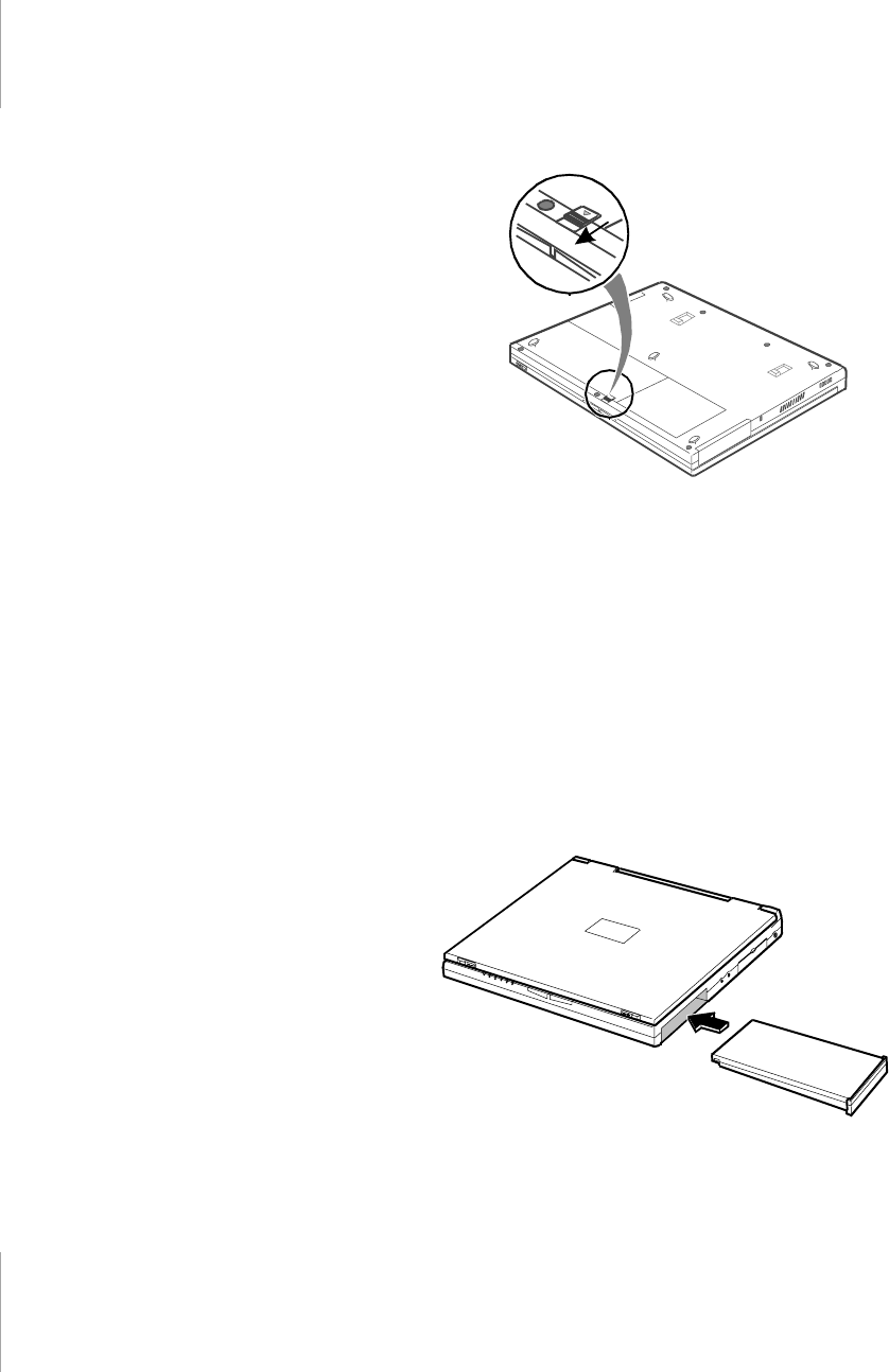
3. Slide the battery release latch toward the front of the computer (Figure 18).
36 User’s Manual
Figure 18. Sliding the Battery Release Latch
4. Grasp the edge of the battery and pull the battery out of the compartment.
To reinsert the battery pack:
1. Turn the computer’s power off.
2. Close the LCD panel and turn the computer over so the bottom of the unit faces
up.
3. Slide the battery pack into the compartment until it snaps into place, see Figure
19.
Figure 19. Inserting the Battery
Using the Battery 37
Monitoring the Battery Charge
Battery life is affected by factors such as the power-management settings in
System Setup, the applications you use, and the brightness of the LCD. Under
normal usage, the battery charge lasts approximately 2.5 hours.
Battery life estimates are subject to variation. The actual life
of your battery may be less than the estimates given in the
documentation.
You can monitor the charge of the battery pack installed in your computer through
the battery gauge.
Using the Battery Gauge
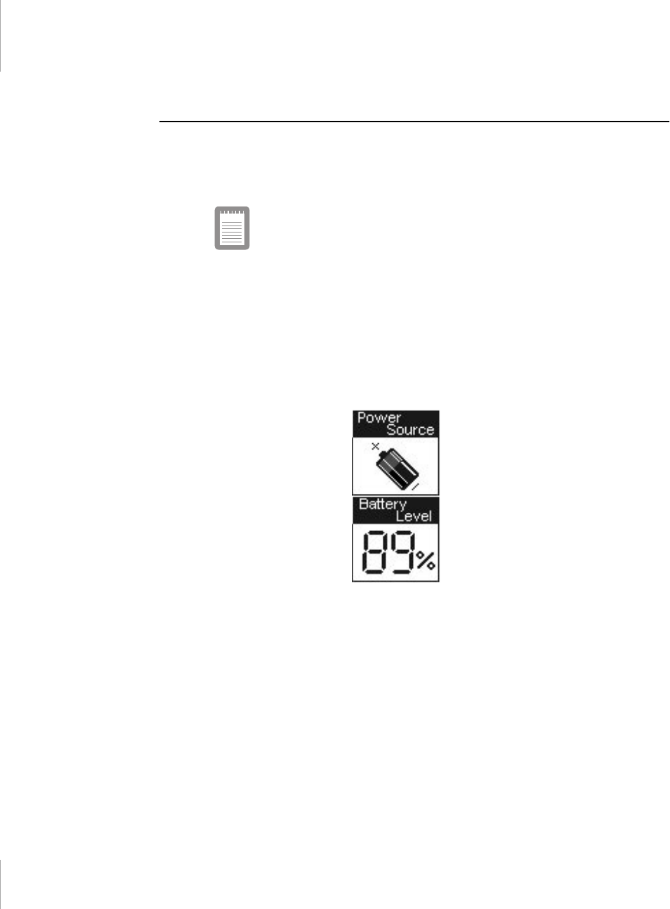
You can display the battery gauge while you are in any program. Press <Fn+F6>
to display the battery gauge on the LCD (Figure 20).
Figure 20. Battery Gauge
The gauge has two sections:
•The top section of the gauge shows a picture of a battery to indicate that the
computer is operating from the battery.
•The bottom section of the gauge shows you the amount of battery charge
remaining.
While the battery gauge is displayed, all keys are disabled except <Esc> key. The
battery gauge closes in a few seconds or by pressing <Esc> key.

38 User’s Manual
Using PowerProfiler to Monitor the Battery
PowerProfiler enables you to set power-management options for computers
shipped with Windows NT installed. To use PowerProfiler to monitor the battery
charge, place the cursor on the battery icon in the right corner of the taskbar.
PowerProfiler shows you the amount of battery charge remaining.
The color of the battery icon also indicates approximate battery charge:
•Green: Charge is adequate to power computer.
•Yellow: Charge is low.
•Red: Charge is very low.
You can determine at what battery charge level PowerProfiler shows the low and
very low colors. The default setting for the very low level is 20 percent battery
charge remaining.
To set battery monitoring options in PowerProfiler:
1. Double-click the PowerProfiler battery icon to open the software.
2. Click the Battery tab.
3. Set options under Battery Status and Alarm Settings.
For more information on PowerProfiler, see the Help option in the PowerProfiler
software.

Using the Battery 39
Battery Warnings
Your computer gives you the following low-battery warnings (Table 4).
Table 4. Battery Warnings
If you cannot run your computer from the battery and the battery will not charge
when you attach the AC adapter, the problem may be that
•The battery temperature is over 95° F (35° C) or below 41° F (5° C). If you
think the battery temperature is too hot or too cold, turn off the computer,
remove the battery, and let the battery reach room temperature. Then try
charging the battery again.
•The battery is defective. Replace the battery with a new battery.
Warnings Condition Action to Take
The computer beeps 5
times (low-pitched
beeps). In Windows 98,
a battery-low warning
appears on screen.
Battery low: The battery
charge is about 10
percent. Approximately
5–10 minutes of battery
charge is left.
Save your work and turn
off your computer, insert a
fully charged battery to
continue. Use the AC
adapter to power the
computer.
The computer beeps 5
times (high-pitched
beeps), with a short time
between beeps. After a
short time, the computer
automatically goes into
rest mode.
Battery very low: The
battery charge is about 3
percent.
Use the AC adapter to
power the computer and
charge the battery.

40 User’s Manual
Using System Setup
The System Setup program enables you to configure your computer hardware and
set security and power-savings options. The settings you choose are stored in
battery-maintained memory (CMOS memory) that saves the information even
when the computer’s power is turned off. When your computer is turned back on,
your computer is configured with the values found in this memory.
Run System Setup if you get a message prompting you to run the program. You
may also want to run System Setup, particularly the first time you use your
computer, to set the time and date, use security or power-management features, or
alter the settings of other features.
Your computer’s version of System Setup may not include all
the fields listed here or may include additional fields. Field
names and order of appearance can vary according to the
version of the BIOS on your computer.
You can use the configuration listing at the back of this manual to record
information specific to your computer. (See ”Recording the Computer Hardware
Configuration” on page 91.) Fill it out as you complete your System Setup
configuration. This list helps you describe your computer if you must contact your
authorized reseller for service or product information.
Starting System Setup
To start System Setup, turn on your computer and then press <F2> when
prompted. The System Setup screen appears.
The top of the System Setup screen has a menu bar with the selections listed in
Table 5.
Table 5. System Setup Menus
Menu Function
Main Changes the basic system configuration.
Advanced Configures advanced features on your
computer.

Using System Setup 41
To open a menu, use the left or right arrow keys to select the menu name.
Table 6 lists the keys you can use to navigate through System Setup.
Table 6. System Setup Navigation Keys
Security Enables security features, including
passwords and backup and virus-check
reminders.
Power Configures power-management features.
Boot Specifies the order of boot devices.
Exit Specifies how to exit System Setup.
Navigation
Key Alternate
Key Function
<F1> <Alt+H> Displays the General Help window.
<Esc> <Alt+X> Exits the current menu.
<Left Arrow>
and <Right
Arrow> keys
Keypad
arrow keys
Select a different menu.
<Up Arrow>
and <Down
Arrow> keys
Keypad
arrow keys
Move the cursor up and down between
fields in the current menu.
<Tab> Moves the cursor forward through the
cells for a highlighted field. If the field
has only one cell, the <Tab> key moves
the cursor down to the next field.
<Tab+Shift> Moves the cursor backward through the
cells for a highlighted field. If the field
has only one cell, the <Tab+Shift> key
combination moves the cursor up to the
previous field.
<Home> <PgUp> Moves the cursor to the field at the top of
the window.
<End> <PgDn> Moves the cursor to the field at the
bottom of the window.
<F5> <-> Scrolls backwards through the options
for the highlighted field.
<F6> <+> or
<Space>
Scrolls forward through the options for
the highlighted field.

42 User’s Manual
An arrow symbol appearing to the left of a field indicates that you can open a
submenu from this field. A submenu contains additional options for a field. To
open a submenu, highlight the field and press <Enter>. Use the same keys to enter
values and move from field to field within submenus as you use within menus.
When you highlight a field, information about the field appears on the right side of
the screen. System Setup also provides a General Help screen that can be opened
from any menu by pressing <F1> or <Alt+H>. The General Help screen lists the
navigation keys with their corresponding alternates and functions.
When a scroll bar appears to the right of a help window, more information is
available than can be displayed in the window. Use the <PgUp> and <PgDn> keys
or the <Up Arrow> and <Down Arrow> keys to scroll through the entire help
document. Press <Home> to display the first page, or press <End> to go to the last
page. To exit the help window, press <Enter> or <Esc>.
If your computer will not boot after you have changed settings in System Setup and
exited the program, reboot and press <F2> to reenter System Setup. Once in
System Setup, you can try to change the values that caused your computer boot to
fail. If the problem persists, press <F9> to load the default values.
Main Menu
When you open System Setup, the Main menu appears. You can make changes to
your computer’s basic system configuration from this menu. The fields displayed
in this menu are described below.
System Time: Sets your computer to the time that you specify, usually the current
time. Enter the hour, minute, and second in the format hh:mm:ss. Use a 24-hour
clock. Use the tab key to move between the hour, minute, and second cells. Use
the hyphen key <-> or <Space> bar to decrease or increase the numbers.
System Date: Sets your computer to the date that you specify, usually the current
date. Enter the month, day, and year in the format mm:dd:yyyy. Use the tab key to
<F9> Sets all the parameters in System Setup
to their default values.
<F10> Exits System Setup and saves the
changes.
<Enter> Executes commands or opens a
submenu.

Using System Setup 43
move between the month, day, and year cells. Use the hyphen key <-> or <Space>
bar to decrease or increase the numbers. This field supports year dates of 2000 and
beyond.
Legacy Diskette A: Specifies a drive type for floppy drive A. Drive A is the floppy
drive that is attached using the external module cable to your computer, see “Using
the Floppy Drive” on page 28. Diskette A options are Disabled and 1.44 MB 3½
(default).
IDE Adapter1 and IDE Adapter2: The Main menu contains two IDE adapter
fields to configure these drives. IDE Adapter1 defines the hard drive installed in
the computer. IDE Adapter2 defines the CD-ROM drive.
To configure your hard drive, move the cursor to select the IDE Adapter1 field in
the System Setup Main menu, and then press the <Enter> key. The IDE Adapter
submenu appears.
Normally, you can use the Auto field in the submenu to automatically set the values
for the other fields in the submenu. Manually set the other fields in this submenu
only if the drive you have installed in your computer is not recognized by System
Setup.
After you make your selections from this submenu, press the <Esc> key to exit
back to the Main menu.
You do not need to configure the drive that came with your computer.
Before attempting to configure a hard drive, make sure you
have the configuration information supplied by the
manufacturer of the hard drive. Incorrect drive settings can
cause your computer to malfunction.
Each IDE adapter field calls up a submenu. The following fields are found in the
submenu:
Type: Configures the drive type. Options are Auto, None, DVD/CD-ROM and
User. All remaining fields in this submenu are then filled with the correct
values for the disk type. If you do not have the documentation that came with
your hard drive, try to use the Auto option as described above.
To configure a drive that is not one of the 39 standard drive types, specify
User. Manually enter the number of cylinders, heads, and sectors for your
drive. Refer to your drive’s user documentation or look on the drive to obtain
this information.
If no drive is installed or if you are removing a drive and not replacing it,
select None.

44 User’s Manual
Cylinders: Configures the number of cylinders for the hard drive. Refer to
your drive’s user documentation or look on the drive to obtain this
information. Before you can make changes to this field, the Type field must be
set to User.
Heads: Configures the number of read/write heads for the hard drive. Refer to
your drive’s user documentation or look on the drive to determine the correct
value to enter for this field. Before you can make changes to this field, the
Type field must be set to User.
Sectors: Configures the number of sectors per track for the hard drive. Refer
to your drive’s user documentation or look on the drive to determine the
correct value to enter for this field. Before you can make changes to this field,
the Type field must be set to User.
Maximum Capacity: Displays the maximum capacity of your hard drive. This
field is for reference only.
Multi-Sector Transfers: Sets the number of sectors per block to the highest
number supported by the drive. Configuration options are Disabled, 2 Sectors,
4 Sectors, 8 Sectors, and 16 Sectors. The default setting for this field depends
on the type of hard drive installed in your computer. Before you can make
changes to this field, the Type field must be set to User or DVD/CD-ROM.
LBA Mode Control: Enables or disables 28-bit addressing of the hard drive,
without regard for cylinders, heads, and sectors. Note that enabling this field
may decrease the access speed of the hard drive. The default setting for this
field depends on the type of hard drive installed in your computer. Before you
can make changes to this field, the Type field must be set to User or DVD/CD-
ROM.
32 Bit I/O: Enables or disables 32-Bit I/O. When Enabled, your hard drive
can work with applications with 32-bit input and output between CPU and
IDE Controller.
Transfer Mode: Selects the method for transferring data between the hard
drive and system memory. Refer to your drive’s user documentation to
specify the correct option for this field. Options are Standard; Fast PIO 1,
Fast PIO 2, Fast PIO 3, Fast PIO 4, FPIO 3 / DMA 1 and FPIO 4 / DMA 2.
Before you can make changes to this field, the Type field must be set to User
or DVD/CD-ROM.
SMART Monitoring: SMART (self-monitoring analysis and reporting
technology) software monitors the performance of your computer’s IDE hard
drive. When the SMART Device Monitoring field is enabled, you receive a
warning message if the SMART software detects an impending drive failure.
This field is for reference only.

Using System Setup 45
Ultra DMA Mode: Enables the hard drive to use ultra DMA transfer mode to
transfer data between the drive and system memory. Options are Disabled,
Mode 0, Mode 1 and Mode 2. Set the Type field to Auto to select the optimum
transfer mode
Memory Cache: Opens a submenu that enables or disables external cache
memory. Cache memory improves system performance by keeping frequently
used computer instructions in memory with a faster access time than DRAM.
The submenu fields are:
Memory Cache: Enables (default) or disables your computer’s (level 2) cache
memory. Normally, do not disable the cache memory unless a program’s
documentation specifies that the computer cache memory must be disabled.
Cache Extended Memory Area: Controls the caching of system memory over
1 MB. Options are Write Back (default), uncached, Write Through and Write
Protect. Normally, Write Back is the optimal setting but if you are
experiencing problems try changing the settings.
Cache D400 - D7FF: Disabled(default), Write Through, Write protect or
Write Back caching of shadowed option ROMs in the D400-D7FF region.
Cache D800 - DBFF: Disabled(default), Write Through, Write protect or
Write Back caching of shadowed option ROMs in the D800-DBFF region.
System Memory: Displays the amount of conventional memory detected by your
computer during startup. This field is for reference only.
Extended Memory: Displays the amount of extended memory detected by your
computer during startup. This field is for reference only.
Advanced Menu
Selecting Advanced from the menu bar displays the Advanced menu.
PS/2 Mouse Configuration: Opens the PS/2 Mouse Configuration submenu if
you press <Enter> when this field is highlighted
The submenu contains these fields:
Mouse Configuration: Enables or disables the touchpad mouse or PS/2 mouse
port. The options for this field are Enabled (default) and Disabled. If you set
this field to Enabled, the PS/2 mouse port is enabled regardless if a mouse is
present or not. If you select Disabled, you disable any installed PS/2 mouse

46 User’s Manual
including the touchpad mouse from working but you free up an IRQ for use by
another device.
Mouse Operation Mode: Enables or disables the touchpad mouse when an
external PS/2 mouse is used. The options for this field are Single Mouse
(default) and Dual Mouse. If you set this field to Single Mouse, the touchpad
mouse is disabled when an external PS/2 mouse is attached. Select Dual
Mouse to have both the touchpad mouse and the PS/2 mouse enabled at the
same time.
I/O Device Configuration: Opens the I/O Device Configuration submenu if you
press <Enter> when this field is highlighted. If you attempt to set two ports to the
same settings, the fields will be marked with asterisks.
The submenu contains these fields:
Serial port A: Configures serial port A. The options for this field are Enabled
(default) and Disabled. If you set this field to Enabled, you can set the Base I/
O Address field to 3F8 IRQ4 (default), 2F8 IRQ3, 3E8 IRQ4, or 2E8 IRQ3.
When the field is set to Enabled, the computer’s operating system uses the
default configuration or the configuration you choose. If you select Disabled,
you free up an IRQ for use by another device.
Serial port B: Configures the infrared port. The options for this field are Auto,
Enabled (default) and Disabled. If you set this field to Enabled, you can set
the Base I/O Address field, the Mode field and the DMA channel field.
Settings for the Base I/O Address are 3F8 IRQ4, 2F8 IRQ3 (default), 3E8
IRQ4, or 2E8 IRQ3. Settings for the mode field are FIR (default), Normal,
IrDA and ASK-IR. Setting the mode field to FIR (fast infrared) enables you to
set the DMA channel to 3 (default) or 1. Select Normal to enable a second
physical serial port.
When the Serial port B field is set to Enabled, the computer’s operating
system uses the default configuration or the configuration you choose. If you
select Disabled, you free up an IRQ for use by another device.
Parallel port: Configures the parallel port. The options for this field are Auto,
Enabled (default) and Disabled. If you set this field to Enabled, you can set
the Mode field and the Base I/O Address field. Settings for the Base I/O
Address field are 378 IRQ7 (default), 378 IRQ5, 278 IRQ7 and 278 IRQ5.
Settings for the Mode are Output only, Bi-directional, EPP (enhanced parallel
port), and ECP (default, extended capabilities port). Selecting the ECP setting
enables you to set the DMA Channel to 1, 2, or 3.
When the Parallel port field is set to Enabled, the computer’s operating
system uses the default configuration or the configuration you choose. If you

Using System Setup 47
select Disabled, you free up an IRQ for use by another device. If Auto is
selected the BIOS or the computer’s operating system chooses the
configuration
Floppy disk controller: Configures the floppy disk controller. The options for
this field are Enabled (default), Auto, and Disabled. When the Floppy disk
controller field is set to Enabled, the computer’s operating system uses the
default configuration for the controller. Selecting Auto enables the operating
system or the BIOS to configure the port.
Installed O/S: Select the operating system installed on your computer. Options are
Win95/Win98 APM, Win98 ACPI/WinNT5.0 and Other. Set this field to Other if
your computer uses an operating system that is not plug and play compliant, such
as Windows NT 4.0. With an operating system that is not plug and play compliant,
you manually change the settings for the COM1, COM2, and LPT ports. The BIOS
will recognize the new settings. Choosing an incorrect setting may cause some
operating systems to behave unexpectedly.
Boot-time Logo Screen: Enables the manufacturer’s logo screen during POST.
The options are Enabled (default) and Disabled. To view the POST screen during
boot choose Disabled.
QuickBoot Mode: Enables certain diagnostics to be skipped during POST which
decreases the time needed to boot the system. The options are Enabled (default)
and Disabled.
CPU BIOS Update: Enables CPU Micro Code updates during POST. The options
are Enabled (default) and Disabled.
USB device: Configures the USB controller. The options for this field are Enabled
and Disabled (default). When the USB device field is set to Enabled, the
computer’s operating system uses the default configuration for the controller. If
you select Disabled, you free up an IRQ for use by another device.
Screen Expansion: Enables the expansion of the screen during boot. When your
computer starts, the screens are in 640x480 resolution during boot and then
automatically change to the resolution you have specified in the Windows settings.
When this field is enabled, the opening screens are expanded beyond 640x480.
The default is Enabled.
TV Standard: Selects the TV Standard to be used when using the TV out
(composite) port .Options are NTSC, PAL (default), PAL-M, PAL-60, NTSC-J and
SCART-PAL.
Local Bus IDE adapter: Enables the integrated IDE local bus adapters. Options
are Both (default), Disabled, Primary and Secondary. The Both option enables

48 User’s Manual
both the primary IDE adapter (for the hard drive) and the secondary IDE adapter
(for the CD-ROM drive) on the computer.
Large Disk Access Mode: Enables your computer’s operating system to work
with drives larger than 540 MB. Choose DOS (default) for Microsoft operating
systems. Choose Other for any other operating systems.
Security Menu
Selecting Security from the menu bar displays the Security menu. Your computer’s
advanced security system allows you to set two different passwords to prevent
unauthorized access to system resources, data, and System Setup. From the
Security menu, you can enable a boot password, disk access, a system backup
reminder, and a virus check reminder.
Security fields marked with an asterisk can only be changed if you start System
Setup with a system supervisor password or if no passwords are in effect. You
cannot access these fields with a user password.
Set User Password: Enables you to set a user password to control access to the
system at boot. See ”Creating a Password” on page 53 for instructions on setting a
password.The user password allows restricted access to the System Setup Security
menu; the user has access only to changing his own password and to enabling or
disabling Password on boot. A supervisor password must be set before a user
password can be set
Set Supervisor Password:* Enables you to set the supervisor password to control
access to the System Setup utility. See ”Creating a Password” on page 53 for
instructions on setting a password.
Password on boot: Determines whether the computer prompts for a password
when starting up. The options are Enabled and Disabled. A supervisor password
must be set before you can enable this option.
Fixed disk boot sector:* Enables you to write-protect the hard drive boot sector
to protect against viruses and alterations. Only a user with the supervisor password
can access this field. The options for this field are Normal (default) and Write
Protect.
Diskette access:.* Enables you to restrict the use of floppy drives. When set to
Supervisor (default), the use of floppy drives is restricted to a user with the
supervisor password. A supervisor password must be enabled before the
Supervisor option can take effect. When set to User, users with either type of

Using System Setup 49
password have access to floppy drives. If the field is set to Supervisor and a user
password is enabled, the user must enter the supervisor password in order to boot
from the floppy drive.
Virus check reminder:* Enables the computer to prompt you to scan the
computer for viruses. The prompt appears each time you start your computer or
reboot until you respond with Y (yes). The options for this field are:
•Daily: Every day when you start your computer for the first time, the prompt
appears.
•Weekly: When you start your computer for the first time each week (after
Sunday), the prompt appears.
•Monthly: When you start your computer for the first time each month, the
prompt appears.
•Disabled: The prompt never appears. This is the default setting.
For a Daily, Weekly, or Monthly prompt to be accurate, System Date in the Main
menu must be set to the current date.
System backup reminder:* Enables the computer to prompt you to backup your
files. The prompt appears each time you start your computer or reboot until you
respond with Y (yes). The options for this field are
•Daily: Every day when you start your computer for the first time, the prompt
appears.
•Weekly: When you start your computer for the first time each week (after
Sunday), the prompt appears.
•Monthly: When you start your computer for the first time each month, the
system backup prompt appears.
•Disabled: The prompt never appears. This is the default setting.
For a Daily, Weekly, or Monthly prompt to be accurate, System Date in the Main
menu must be set to the current date.
Power Menu
The Power menu of System Setup allows you to enable and adjust your computer’s
sophisticated power-saving features. Enabling these features extends the life of the
battery.

50 User’s Manual
If your computer shipped with Windows 98 installed, Windows 98 Power
Management works with the settings in the Power Management option on the
Control Panel.
If the AC adapter is plugged in all power management is disabled.
Power Saving Mode: Sets the power management mode. Choosing modes
changes the system power management settings. The options are Maximum Power
Savings (default) and Maximum Performance. Maximum Power Savings
conserves power by slowing down the microprocessor while Maximum
Performance does not slow the microprocessor.
Standby Timeout: Sets the period of computer inactivity (no user input or device
activity) that must pass before your computer automatically goes into standby
mode. In standby mode some devices are turned off (including the LCD screen)
and the microprocessor clock is stopped. You can disable this option by selecting
Off, or you can specify a Standby Timeout delay time of from 1 to 16 minutes. The
default is 1 Minute.
Rest Mode: Specifies the type of rest mode your computer enters:
•Save To Disk (default): Provides the greatest power-saving capabilities by
essentially turning off your computer. In the save to disk mode, all system
logic (except for your computer wakeup circuitry and battery charger) is
turned off. During save to disk mode, the DRAM and video memory are saved
to the hard drive and are restored when your computer resumes from rest.
•Power On Suspend: Saves power by turning off the microprocessor and DMA
clocks, video, and all controllable peripheral devices. Some power is still used
when your system is in this mode. This rest mode is also known as suspend to
RAM.
When the computer enters save to disk mode, it will not resume normal
operation at a specified time no matter how the Resume On Time field is set.
Rest Timeout: Sets the amount of time that the computer needs to be in Standby
before entering Rest Mode. You can disable this option by selecting Off. The
default setting is 10 min.
Resume On Time: Enables the computer to resume operation from rest mode at a
scheduled time. The computer will resume only if the Rest Mode field is set to
Power On Suspend, not Save To Disk. If you set this field to On, you must set the
Resume Time field as well. The default setting is Off.
Resume Time: Specifies the time for your computer to automatically resume from
rest mode. Enter two-digit numbers to indicate the hour, minutes, and seconds in

Using System Setup 51
the format hh:mm:ss. Use a 24-hour clock. Use the tab key to move between the
hour, minute, and second cells. Use the hyphen key <-> or <Space> bar to decrease
or increase the numbers. You must set this option if you enable Resume On Time.
Boot Menu
The Boot menu enables you to select a boot device and set boot options.
Floppy check: Enables a check of the floppy drive during the tests performed by
the computer at startup. When this field is enabled, a complete POST is performed
at startup. The options are Enabled and Disabled (default).
Summary screen: Displays the system configuration when the computer starts.
The options are Enabled and Disabled (default).
Boot Device Priority: Enables you to select the order in which the computer
attempts to boot from different devices. The field has three options: ATAPI CD-
ROM Drive, Diskette Drive and Hard Drive.
To choose a device as the first, second, or third boot device:
1. Press <Enter> at the Boot Device Priority field
2. Highlight the option with the <Up Arrow> or <Down Arrow> key.
3. Press the <Space> bar or <-> (hyphen key) until the option moves up or down
in the list of options and the number 1, 2, or 3 appears beside the option.
4. Press <Esc> to return to the Boot menu.
The default setting is 1. Diskette Drive, 2.Hard Drive and 3.ATAPI CD-ROM
Drive.With these default settings, your computer first attempts to boot the floppy
drive. If there is no floppy disk in the floppy drive, the computer will attempt to
boot from the hard drive and then a bootable CD-ROM in the CD-ROM drive.
Exit Menu
Select Exit from the menu bar to display the Exit menu.
Pressing <Esc> does not exit this menu. You must select one
of the options from this menu or a menu bar item to exit this
menu.

52 User’s Manual
Exit Discarding Changes: Enables you to exit System Setup without saving your
changes. When you select this item and press <Enter> a message appears asking
you if you want to save changes before exiting. Choose No and press <Enter> to
exit without saving changes. Choose Yes and press <Enter> to save changes and
exit.
Exit Saving Changes: Enables you to exit System Setup and saves your changes.
When you select this item and press <Enter>, a message appears asking you if you
want to save your changes and exit System Setup. Choose Yes and press <Enter>
to save your changes and exit. Choose No and press <Enter> to remain in System
Setup.
Load Setup Defaults: Loads the default values for all System Setup parameters.
When you select this option and press <Enter>, a message appears asking if you
want to load the default configuration. Choose Yes and press <Enter> to load
default settings and remain in System Setup. Choose No and press <Enter> to
retain your changes and remain in System Setup.
Discard Changes: Enables you to discard the selections you have made and
restore the values you previously saved. When you select this option and press
<Enter>, a message appears asking if you want to load the previous configuration.
Choose Yes and press <Enter> to load the previous settings and remain in System
Setup. Choose No and press <Enter> to retain your changes and remain in System
Setup.
Save Changes: Saves your selections without exiting System Setup. When you
select this option and press <Enter>, a message appears asking if you want to save
configuration changes. Choose Yes and press <Enter> to save changes and remain
in System Setup. Choose No and press <Enter> to discard changes and remain in
System Setup.
Battery Calibration: Enables you to discharge the system battery completely for
a more accurate battery level detection. This option only works with the smart
battery if the AC Adapter is not plugged in.

Using System Security 53
Using System Security
This section describes the security options provided with your computer.
System Passwords
The computer provides two levels of password security: administrative-level
(supervisor) and user-level (user). Either password prevents unauthorized access
to the computer. The supervisor password enables full access to all System Setup
fields. The user password enables full access to only the Set User Password and
Password on boot security fields and read access to all other System Setup fields.
(See ”Security Menu” on page 48 for a complete list of System Setup security
fields.)
If multiple users have access to the computer (such as in a network environment),
a supervisor password can prevent unauthorized access to certain security options.
Choose the type of password security that is appropriate for your work. If you want
to set a user password, you must set a supervisor password first.
Creating a Password
To create a password:
1. At startup, press <F2> to open System Setup.
2. Use the <Right Arrow> key to select the Security menu.
3. Use the <Down Arrow> key to select Set Supervisor Password or Set User
Password.
4. Press <Enter>. The Set Password dialog box appears.
5. Type a password of up to seven characters. You can enter letters or numbers,
but you cannot use the function keys, such as <Shift>. Your computer does not
distinguish between capitalized and lowercase letters in your password. As you
type the password, the cursor moves but your password does not appear on the
screen.

54 User’s Manual
6. Press <Enter> after you have typed your password. The computer prompts you
to reenter your password for verification.
7. Type your password again and press <Enter>. A message appears telling you
that the changes have been saved. Press <Enter> again to return to the Security
menu.
8. Press <Esc> to go to the Exit menu.
9. Select Exit Saving Changes, press <Enter>, and press <Enter> again to restart
the computer.
Deleting a Password
To delete the password:
1. At startup, press <F2> to open System Setup.
2. Type your password when prompted and press <Enter>.
3. Use the <Right Arrow> key to select the Security menu.
4. Use the <Down Arrow> key to select Set Supervisor Password or Set User
Password.
5. Press <Enter>. The computer prompts you to enter the current password.
6. Press <Enter>. The computer prompts you to enter a password. Do not type
anything.
7. Press <Enter>. The computer prompts you to re-enter the password. Do not
type anything.
8. Press <Enter>. A message appears telling you that the changes have been
saved. Press <Enter> again to return to the Security menu.
9. Press <Esc> to go to the Exit menu.
10. Select Exit Saving Changes, press <Enter>, and press <Enter> again to restart
the computer.
Requiring a Boot Password
After you create a supervisor or user password, you can enable the computer to
prompt for a password each time it starts.

Using System Security 55
To enable the prompt, select the option Enabled in the Password on boot field in
System Setup. For more information about the Password on boot field, see
“Security Menu” on page 48.
Locking the Hard Drive Boot Sector
If you have an supervisor password, you can lock the hard drive boot sector to
protect against viruses or alterations.
To lock the hard drive boot sector, select the option Write protect in the Fixed disk
boot sector field in System Setup. For more information about the Fixed disk boot
sector field, see “Security Menu” on page 48.
Locking the Floppy Drive
If you have an supervisor password, you can lock the floppy drive so that a user
with only a user password cannot load personal software, which may introduce a
virus into the computer.
To enable the floppy lock, select the option Supervisor in the Diskette access field
in System Setup. For more information about the Diskette access field, see
“Security Menu” on page 48.
Locking the Keyboard
The keyboard lock enables you to protect your system when you walk away from
it for a time. To use the keyboard lock, you must first enable a password through
System Setup. (See ”Creating a Password” on page 53 for instructions.To lock
your keyboard, press <Fn+F7>. To unlock your keyboard, type your password and
press <Enter>

56 User’s Manual
Using Power Management Options
Your computer includes power-management options that can help the battery
charge last longer and extend the life of the battery, LCD panel, and other
components. Power-management options slow down or shut off system
components when the components are not being used.
Power management slows down system performance. Your computer runs fastest
with the AC adapter attached, when no power management is in effect. If you
disconnect the AC adapter the LCD brightness is reduced to save power. See page
15 for information on increasing the LCD brightness.
If your computer shipped with Windows 98 installed, Windows 98 Power
Management works with the settings in the Power Management option on the
Control Panel. If your computer uses DOS or Windows 95, Power Management
works with the settings in System Setup
If your computer shipped from the factory with Windows NT installed,
PowerProfiler power management software was included.
Maximum Power Saving Mode
In maximum power saving mode, the microprocessor runs at slow speed to
conserve power. To enable this mode , set the Power Saving Mode field in System
Setup to maximum power saving mode.
Standby Mode
The Standby Timeout field in System Setup enables you to specify the time period
that the computer can remain idle (no user input or disk activity) before the
computer enters standby mode. You can disable this option by selecting Off, or you
can specify a Standby Timeout delay time of from 1 to 16 minutes.
In standby mode, the system and video memory and the video controller slow
down. The LCD backlight, hard drive, floppy drive, PC Card controller, and some
other devices turn off to save energy. DPMS (a form of monitor power
management) to an external monitor is invoked.

Using Power Management Options 57
To resume from standby, touch the touchpad. Do not press any keys on your
keyboard.
If you press a key to resume from standby, your computer will
recognize the function of the key you pressed and perform
that function. For example, if you press <N> and a document
is open, an
“n”
is typed into your document.
If you enable both standby and rest modes, your computer enters standby when the
delay time you chose for standby has elapsed, and then enters rest mode when the
delay time you chose for rest mode has elapsed since the computer entered
standby.
Rest Mode
The Rest Timeout field in System Setup enables you to specify the time period after
the entering standby before the computer enters rest mode. You can disable this
option by selecting Off, or you can specify a Rest Timeout delay time of 5 to 60
minutes.
The Rest Mode field in System Setup defines what type of rest mode your
computer enters, see "Rest Mode" in “Power Menu” on page 49 for more
information.
You can press <Fn+F11> to manually place your computer into rest mode.
When you use the <Fn+F11> key combination, your computer
may postpone entering rest mode during a critical operation,
such as reading from or writing to the hard drive.
To resume to full-power mode, press the power button.
Once all devices return to full-power mode, all active software applications and
system states are restored to exactly how they were before your computer entered
rest mode.
When your computer enters or resumes from save to disk mode, screens appear
indicating system status. These status screens do not appear when the computer
enters or resumes from power on suspend.

58 User’s Manual
Rest Mode Precautions
Observe the following precautions when using rest mode:
•Save all open files before you press <Fn+F11> to manually place your
computer into rest mode.
•Do not try to resume to full-power mode using battery power if the battery
charge is low. If the battery charge is too low, the system may not be able to
resume fully. Plug in the AC adapter if your computer cannot resume normal
operation because of a low battery charge.
When your computer is in power on suspend or save to disk
mode, do not connect or remove any devices (including PC
Cards or external modules) because you may damage the
computer or resume to full power may fail. If a floppy disk is
in the floppy drive, do not remove it or switch it with another
disk.
However, you can plug in the AC adapter if the resume to full
power fails because of a low battery charge.
When the computer is in save to disk mode, you can remove
and replace the battery.
Using PowerProfiler
PowerProfiler enables you to set power-management options for computers
shipped with Windows NT installed. To open the PowerProfiler window, double-
click the battery icon on the right corner of the Windows taskbar. If you click the
icon with the right mouse button, a menu appears with an option to put the
computer in rest (rest mode).
Click the Standard tab in PowerProfiler to set timeouts for the LCD and the hard
drive. You can also set power management to be enabled Always, Battery Only, or
Never. The Advanced screen in PowerProfiler enables resume from rest options,
and the Battery screen enables options to conserve battery life.
Keep the following in mind when using PowerProfiler:
•If you disable power management in PowerProfiler, the setting overrides any
power-management settings in System Setup.

Using Power Management Options 59
•If you enable LCD and hard drive timeouts in PowerProfiler and the standby
timeout in System Setup, the LCD and hard drive turn off when the shortest
timeout period in either program passes.
•If you disable the Resume on Time field in System Setup, the same field in
PowerProfiler is also automatically disabled. An easy way to work with these
two fields is to set the resume time to 0 in System Setup and set the actual
resume time that you desire in PowerProfiler.
PowerProfiler maintains the accuracy of the system clock
when the computer resumes from rest mode. If PowerProfiler
is closed or removed from your hard drive, your system clock
may not be accurate when your computer resumes from rest
mode.
For more information on PowerProfiler, see the Help option in the PowerProfiler
software.

60 User’s Manual
Creating a Save to Disk Partition
The hard drive shipped in your computer has a save to disk partition in which data
from system and video memory is stored during save to disk mode. The partition
is the maximum size needed for your computer and supports system memory of
160 MB.
If you need to repartition your hard disk, you can create a save to disk partition
using the Phoenix PHDISK utility, provided with your computer.
If you do not intend to use save to disk mode, you do not need
to create a save to disk partition.
To create the save to disk partition:
To create a save to disk partition, you need a DOS bootable
disk that contains PHDISK, FDISK and the Format command.
1. Create a Phoenix PHDISK utility disk from the Utility CD-ROM.
2. Shut down your computer.
3. Connect the floppy drive to the computer. (See ”Connecting External
Modules” on page 25 and see “Using the Floppy Drive” on page 28 for
instructions.). Switch on your computer.
4. Enter System Setup and under the Boot menu, set Diskette Drive as the first
boot device. (See ”Using System Setup” on page 40 for information on setting
options.)
5. Insert the bootable disk into the floppy drive and start your computer.
6. After your system boots, remove the startup disk from the floppy drive and
insert the PHDISK disk.
7. At the A: prompt, type:
phdisk /c 167936 /p
and then press <Enter>.

Creating a Save to Disk Partition 61
PHDISK automatically creates a save to disk partition of the maximum size for
your computer.
When the save to disk partition has been created, the following message
appears:
Save to disk partition created successfully
If you do not intend to use the save to disk mode, you can
delete the save to disk partition on a hard drive using PHDISK
/delete. Then you can repartition and reformat the save to disk
partition for some other application. Back up your hard drive
before deleting the partition if you feel unsure of how to do
this.

62 User’s Manual
Changing the Video Configuration
Your computer includes an TFT LCD or active-matrix display. The capabilities of
the screen plus the video drivers installed on the computer determine the quality of
the image your LCD can display.
The following sections describe the display capabilities of your computer.
Resolution and Color Depth
The resolution of the LCD is the sharpness of the image it can display. Resolution
is measured by the number of pixels (individual dots) displayed on the entire
screen. In general, the more pixels the LCD can display, the better the image.
Your LCD screen is either SVGA or XGA:
•The maximum display for the SVGA LCD screen is 800x600, about 480,000
pixels.
•The maximum display for the XGA LCD screen is 1024x768, about 800,000
pixels.
The number of colors the LCD can display is measured by how many bits the LCD
uses to represent each pixel:
•8-bit color can support 256 different colors.
•16-bit color can support 64 K (65,536) colors.
•24-bit color can support 16 M (16.8 million) colors.
•32-bit color can support 16 M (16.8 million) colors.
24-bit color uses the RGB color model.
32-bit color uses the CMYK color model which gives better printed color
matching.
Table 7 lists the basic video mode capabilities and maximum colors supported by
your computer.

Changing the Video Configuration 63
Table 7. Video Driver Capabilities
All these video modes can be displayed on an external monitor. However, if you
disconnect an external monitor that was attached to your computer and then start
the computer, the LCD may revert to a different resolution than the one you chose
for the external monitor.
Configuring Display Features
The following sections describe how to configure the display settings on your
computer.
Software
Drivers Resolution Supported Number of
Colors
Windows 98 320x200, 320x240, 512x384, 640x350, 640x400,
640x480, 720x480,720x576, 800x600, 864x480,
1024x600, 1024x768, 1152x864, 1280x1024,
1600x1200
256
320x200, 320x240, 512x384, 640x350, 640x400,
640x480, 720x480,720x576, 800x600, 864x480,
1024x600, 1024x768, 1152x864, 1280x1024,
1600x1200
65,536
320x200, 320x240, 512x384, 640x350, 640x400,
640x480, 720x480,720x576, 800x600, 864x480,
1024x600, 1024x768, 1152x864, 1280x1024
16.8 million
320x200, 320x240, 512x384, 640x350, 640x400,
640x480, 720x480,720x576, 800x600, 864x480,
1024x600, 1024x768, 1152x864 16.8 million
Windows
NT® 4.0 640x480, 800x600, 1024x768, 1152x864,
1280x1024, 1600x1200 256
640x480, 800x600, 1024x768, 1152x864,
1280x1024, 1600x1200 65,536
640x480, 800x600, 1024x768, 1152x864,
1280x1024 16.8 million
640x480, 800x600, 1024x768, 1152x864 16.8 million

64 User’s Manual
Selecting a Monitor Type
When you attach an external monitor to your computer, Windows 98 automatically
selects display settings for it (this feature is not available in Windows NT). If you
wish, you can adjust the display settings by selecting a monitor type:
1. Click the Start button on the Windows 98 taskbar.
2. Select Settings.
3. Click Control Panel. The Control Panel window appears.
4. Double-click the Display icon. The Display Properties window appears.
5. Click the Settings tab. The Settings screen appears.
6. Click the Advanced Properties button. The Advanced Properties screen
appears.
7. Click the Monitor tab.
8. Click the Change button. The Update Device Driver Wizard screen appears.
9. Click the Next button.
10. Select the Display a list of all the drivers in a specific location radio button and
click the Next button.
11. Select the Show all hardware radio button.
12. Select a manufacturer and model setting that matches your external monitor.
Your computer has an intelligent video chip set that automatically matches
your LCD panel resolution and frequency when an external monitor is not
present.
13. Click the Next button.
14. The Update Device Driver Wizard screen appears showing the driver location
of the device you have selected. Click the Next button.
15. Follow any prompts that appear on the screen.
Changing Color Depth and Resolution
To change the color depth and resolution of your LCD or external monitor:
1. Click the Start button on the Windows taskbar.
2. Select Settings.

Changing the Video Configuration 65
3. Click Control Panel. The Control Panel window appears.
4. Double-click the Display icon. The Display Properties window appears.
5. Click the Settings tab. The Settings screen appears.
6. To change the color depth, click the arrow next to Color palette and select the
color depth you want.
7. To change the resolution, click and drag the knob under the Screen area until
you select the resolution you want.
8. Click the OK button.
9. Follow the prompts that appear on the screen.
Changing the Video Driver
It is possible that you may want to update your video driver or that your installed
video driver has become corrupt so that the display is unusable.
In Windows 98:
1. Click on the Start Button. The Start Menu appears.
2. Select Settings and click on Control Panel, double click on Display. The
Display Properties window appears.
3. Click the Advanced button. The properties screen for your currently installed
video driver appears
4. Select the Adapter menu.
5. Click the Change button. The Update Device Driver Wizard window appears.
6. Click the Next button.
7. Select Display a list of all the drivers in a specific location, so you can select
the driver you want. Click the Next button.
8. Click the Have disk button. If the driver is on a floppy disk insert it into the
floppy drive or if you want to use the origianl factory driver insert the Utility
CD-ROM into the CD-ROM drive. Click the Browse button and locate driver
you want to install. Click the OK button.
9. Select the new driver in the Select Device screen and click the Ok button.

66 User’s Manual
10. Click the Next button to install the new driver and follow any directions on the
screen to finish setting the display properties.
In Windows NT 4.0:
1. As the computer starts, select Windows NT Workstation Version 4.00 [VGA
mode] as the operating system and press <Enter>.
2. Log on to the computer as supervisor. The Invalid Display Settings window
appears.
3. Click the OK button. The Display Properties window appears.
If the Change Display window appears, go to step 6.
4. Select the Settings menu.
5. Click the Display Type button. The Display Type window appears.
6. Click the Change button. The Change Display window appears.
7. Click the Have disk button. If the driver is on a floppy disk insert it into the
floppy drive or if you want to use the origianl factory driver insert the Utility
CD-ROM into the CD-ROM drive. Click the Browse button and locate driver
you want to install. Click the OK button.
8. A line similar to the following line appears under the Display option: ATI
Technologies Inc. 3D Rage LT Pro.
9. Click OK. The Third-Party Driver window appears.
10. Click Yes. The driver is copied. A window appears telling you the driver has
been successfully copied.
11. Click OK. Remove the disk from the floppy drive. Close the open windows on
the screen.
12. Click Yes when prompted to restart the computer. As the computer restarts,
select Windows NT Workstation Version 4.00 as the operating system and press
<Enter>.
13. Log on as supervisor. The Invalid Display Settings window appears.
14. Click the OK button. Click the Test button at the Display Properties window
and follow any directions on the screen to finish setting the display properties.

Working with PC Cards 67
Working with PC Cards
By installing PC Cards, you can add functions to your portable computer similar
to those found on add-in boards for desktop computers. Available PC Cards
include:
•Input/output, such as modem, network, pager, video capture, and SCSI cards.
•Storage, such as hard drive cards.
•Combo cards, such as a combination modem and network card.
Your computer includes the following PC Card support:
•Two PC-Card slots: You can install Type I, II, or III cards in the slots. Type
III cards are thicker than Types I and II. If you install a Type III card in the
bottom slot, you cannot install a card in the top slot.
•CardBus hardware and software: CardBus enables the computer to use 32-bit
PC Cards. Windows 98 supports 32-bit and 16-bit PC Cards. The
SystemSoft® CardWizard™ for Windows NT program, provided with
systems that ship from the factory with Windows NT installed, also supports
both 32-bit and 16-bit cards.
•Zoomed video: Both PC Card slots and the video chip on your computer
support zoomed video. When you install a zoom video PC Card in either slot,
data can be transferred directly from the PC Card to video and audio systems
without going through the microprocessor. Video conferencing and real-time
multimedia devices, such as video cameras, are supported by zoom video.
To use the CardBus and zoomed video technology, install the
CardBus and Zoomed Video drivers provided with your PC
Card. If no drivers were supplied with your card, contact the
PC Card manufacturer. ATA and modem PC Cards do not
require extra drivers.
The following sections tell you how to work with PC Cards.
Maintaining PC Cards
To maintain your PC Cards, follow these guidelines:
•Keep cards away from excessive heat, direct sunlight, and liquids.
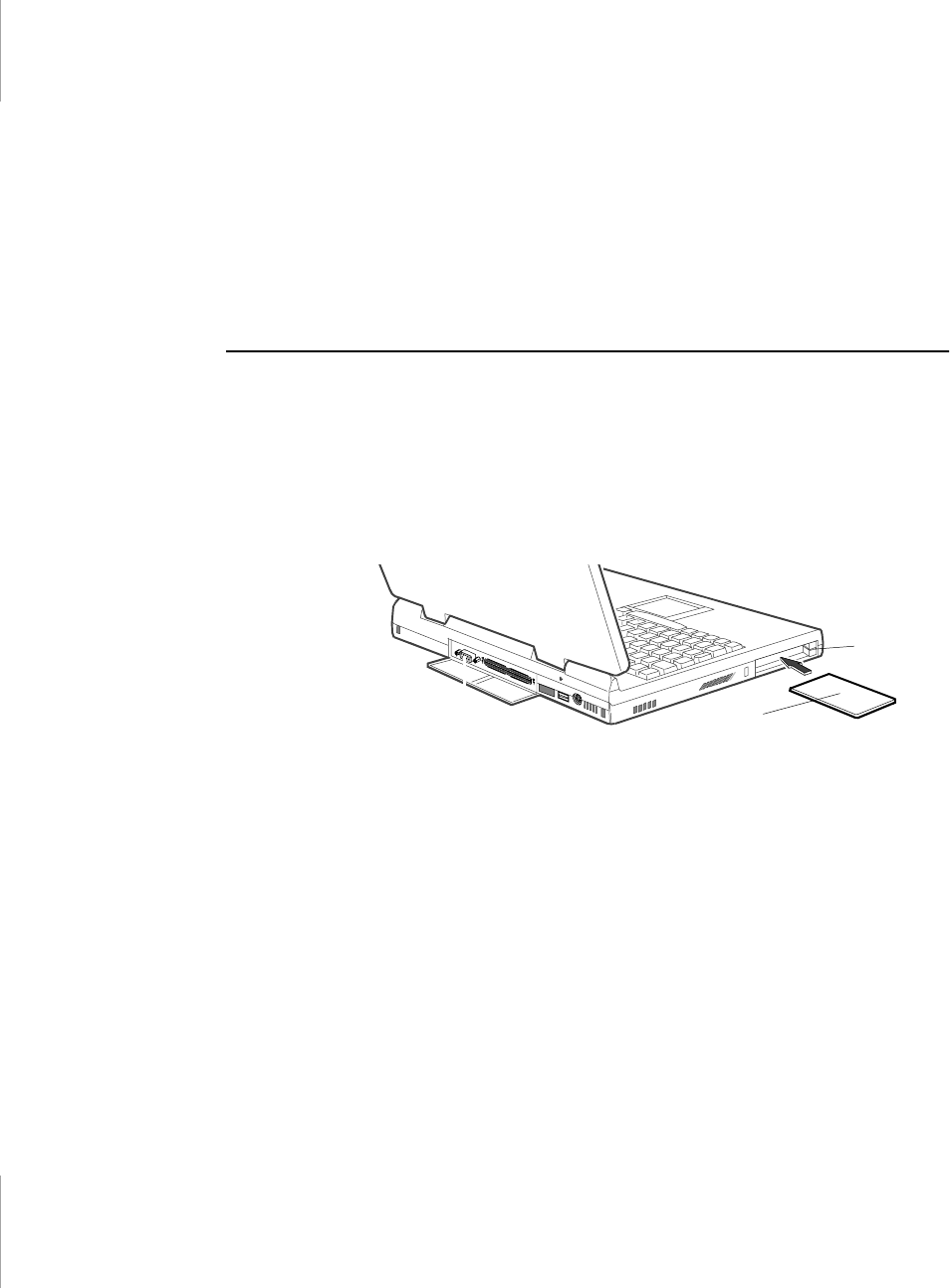
68 User’s Manual
•Do not drop, bend, flex, or crush cards when handling.
•Keep dust, magnets, and static electricity away from PC Cards.
•When a card is not in use, carry it in its protective carrying case.
•Some PC Cards include cables that extend from the back of the cards. Be
careful not to bend or put excessive strain on these cables.
Using PC Cards
You can install PC Cards while the computer is on.
To insert a PC Card into a slot:
1. Open the slot door.
2. Align the card with a slot and insert the card into the slot until it locks in place
(Figure 21).
Figure 21. Inserting a PC Card
To remove a PC Card from a slot:
1. Open the slot door.
2. Press the eject button once and it springs out.
3. Press the eject button again to eject the card, see Figure 22 on page 69
PC Card
Eject buttons
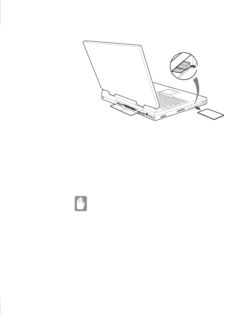
Working with PC Cards 69
Figure 22. Removing a PC Card
Windows 98
Windows 98 automatically assigns computer resources (such as communication
ports and memory addresses) to a PC Card installed in your computer. For further
information on configuring a PC Card in Windows 98, see the index entry PC
cards in the Windows Help. Windows 98 also handles power management for PC
Cards.
To remove a PC Card from your computer:
Use the following procedures to remove PC Cards, or you
may lose data that is being stored to a card.
1. Click the PC Card icon on the taskbar.
2. Click Stop for the card you want to remove. A message appears telling you it
is OK to remove the card.
3. Push the card eject button on the side of the PC Card slot.
4. Pull the card out of the PC Card slot.
PUSH

70 User’s Manual
Windows NT 4.0
Systemsoft Card Wizard is shipped with notebook computers that use Windows
NT as the operating system. When you install a PC Card, CardWizard attempts to
configure it automatically. If Card Wizard successfully assigns system resources
to your card, the computer beeps twice.
If CardWizard cannot automatically configure your PC Card, the computer beeps
once and a message appears telling you that the card has not been configured. Click
the Wizard button on the CardWizard window. CardWizard then analyzes why the
card was not configured and fixes the problem or gives you information to help fix
the problem.
CardWizard works with the PowerProfiler program to manage PC Cards when the
computer enters or resumes from rest mode. CardWizard gives you instructions to
prevent loss of data before the computer enters rest mode or may stop the computer
from entering rest mode. ATA and modem cards can enter rest mode.
Follow these guidelines when using PC Cards with CardWizard:
•LAN (local-area network) cards can be inserted while the computer is on but
should be removed only when the system is turned off.
•SCSI cards should be inserted at startup to enable Windows NT to find the
device attached to the SCSI card. SCSI cards can be removed when the
computer is turned off. If you restart your computer without the SCSI card
installed, a message may appear telling you that a service did not start. You
can ignore this message.
•Modem and ATA cards can be inserted and removed while the computer is
on.
Before you remove a modem or ATA card from your
computer, stop the card through the CardWizard program or
you may lose data.
To stop and remove a PC Card from your computer:
1. In the SystemSoft CardWizard screen, click with the right mouse button on the
name of the card you want to remove.
2. Click Stop in the Actions menu. A red stop sign appears on the main screen
when the card is stopped.
3. Click OK.
4. Push the card eject button on the side of the PC Card slot.

Working with PC Cards 71
5. Pull the card out of the slot compartment.
For more information on using the CardWizard program, see the CardWizard
Help.

72 User’s Manual
About Drivers and System Resources
This section gives you basic information about drivers and system IRQs.
Drivers
A driver is a program that enables the operating system to work with a hardware
device. Your computer includes drivers for the audio, video, touchpad, keyboard,
CD-ROM drive, hard drive, floppy drive, and PC Card controller. When you add
a device to your computer, such as a printer, you must install a driver for that
device.
Different drivers are used by different operating systems. If you need drivers for
an operating system other than Windows 98 or Windows NT, check the Drivers
directory in your Utility CD-ROM, drivers for some other operating systems are
included there.
IRQs
Most of the devices in your computer or connected to your computer need their
own IRQ. The IRQ is a hardware line that a device can use to send signals to the
microprocessor. When the device needs the microprocessor’s service, the device
sends an interrupt request signal to the microprocessor.
The number of IRQs available for any computer is limited by industry standards.
Because it ships with numerous features, the computer uses most of the available
IRQs. If you add another device to your computer, you may need to disable an
existing device to free up an IRQ for the new device. IRQ resources are of
particular concern when the computer is attached to a docking device.
The IRQs that are used by default on your computer are listed in Table 8.
Table 8. IRQs
IRQ Component (Windows 98) Component (Windows NT
0System timer System timer
1Keyboard Keyboard

About Drivers and System Resources 73
In Windows 98, you can configure a device so that the device is disabled when you
connect your computer to a docking station but enabled when the computer is not
connected to the docking station. With this configuration, an IRQ is available for
a peripheral device that you can connect the docking station.
Enabling the Infrared Port
If your computer’s operating system is Windows 98, you can enable and use the
infrared port. If your computer’s operating system is Windows NT 4.0 you will
need to purchase additional software to use the Infrared port.
If you are unable to transfer files with the infrared port, check the following:
•Make sure the Serial port B field in System Setup is set to 2F8, IRQ 3. The
field is in the Advanced Menu under I/O Device Configuration.
•The receiving device must be positioned properly. There must be no more
than three feet (or one meter) of distance between the computer’s infrared port
and the receiving infrared device.
2Internal Controller Internal Controller
3Infrared Port (COM 2) (available)
4Serial Port (COM 1) Serial Port (COM 1)
5Sound, USB Sound, USB
6Floppy controller Floppy controller
7ECP Printer Port (LPT1) ECP Printer Port (LPT1)
8System CMOS/ Real Time Clock System CMOS/ Real Time Clock
9(available) (available)
10 (available) (available)
11 CardBus PC Card Controller CardBus PC Card Controller
12 Touchpad, PS/2 mouse Touchpad, PS/2 mouse
13 Numeric data processor Numeric data processor
14 Primary IDE Controller (hard drive) Primary IDE Controller (hard drive)
15 Secondary IDE Controller (CD-ROM
drive)
Secondary IDE Controller (CD-ROM
drive)
IRQ Component (Windows 98) Component (Windows NT

74 User’s Manual
•The sending and receiving devices need to be on the same level vertically.
Place them on the same table if possible.
•Make sure the infrared ports on the sending and receiving devices face each
other, with no more than a 30 degree angle between the two infrared ports.
•Make sure that nothing is obstructing the file transfer path between the
computer’s infrared port and the receiving infrared device.
If you still cannot transfer a file, see the documentation for the infrared software.
Service Pack 3 for Windows NT 4.0
Microsoft® Service Pack 3 (SP3) is included with computers shipped from the
factory with Windows NT installed. Any time you change or add components to
your Windows NT system, you need to reinstall SP3.
The version of SP3 on your computer’s hard drive includes the correct video driver
for your system. If possible, always install this version on your computer.
To install SP3:
1. Run the executable file. On your computer’s hard drive this file is located at
C:\SP3\I386\update.
2. Follow the instructions on the screen with these exceptions:
a. When you are prompted to overwrite the uninstall directory, click the
Yes button.
a. When a prompt identifies your pcmcia.sys file as an OEM-installed file
and asks you to overwrite the version of the file on your system with
the service pack version, click the No button.
If you install any future service packs on your computer,
make sure that, when you are prompted, you do not
overwrite
the pcmcia.sys file, or you may be unable to use your
computer.
If you install SP3 from any source other than your computer’s hard drive, the video
driver that was installed on your computer at the factory is overwritten. After you
install the service pack, you must reinstall the video driver the first time you restart
your computer, see “Changing the Video Driver” on page 65 for more infomation.

Troubleshooting 75
Troubleshooting
If you ever have difficulty running your computer, follow these steps:
1. Consult the following sections for advice on how to handle system problems.
2. If steps 1 does not help you to resolve the problem, contact your reseller for
assistance.
Operating Problems
This section tells you what to do if you have problems running your computer. If
any problem persists after you take corrective action, contact your reseller for
assistance.
The computer does nothing when you turn it on.
Has the battery run down? Connect the AC adapter or auto adapter to get power
and recharge the battery. Try turning on the computer again.
The computer is not behaving as expected.
Operating your computer at high speed with the cache enabled may cause system
instability and incompatibility with some operating systems. If your computer is
not behaving as expected and no error messages appear, disable the Memory
Cache setting in the Memory Cache field of System Setup.
Nothing appears on the LCD panel when you turn on the computer.
Adjust the brightness on the LCD. Are you using an external monitor? If so, press
<Fn+F5> to return to the LCD panel.
Nothing appears on the external monitor when you switch the display to it.
Is the monitor properly connected to the computer? Is the monitor’s power cord
connected to an AC wall outlet? Check the brightness and contrast controls on the
monitor. Does the program appear on the LCD panel instead of the external
monitor? If so, press <Fn+F5> to switch to the monitor. Try turning the monitor
off and on again.
The external monitor displays flashes or waves.
Check the cables between the monitor and the computer. Are they properly
installed?

76 User’s Manual
Some of the letter keys type numbers instead of the indicated letters.
Is the Num Lock light on? If so, the numeric keypad on the keyboard is active. To
return the keypad keys to typing letters, press <Num Lock>.
Battery power seems to run out faster than expected.
If you are running the computer from the battery rather than the AC adapter, make
sure that you set the Battery Power Saving Mode field in System Setup to
Maximum Power Saving Mode. This setting enables the microprocessor and the
hard drive to slow down when the computer is idle.
You can also enable other power-saving options through System Setup. Set the
timeout times in the Standby Timeout and Rest Timeout fields to the shortest times
to ensure maximum power savings.
Certain software programs “hang” during operations when there is no
interaction with the keyboard or peripheral devices.
Your computer may be in standby or rest mode. Tap the touchpad to resume from
standby or press the power button to resume from rest.
A serial or parallel device attached to a serial or parallel port on the rear
panel of the system unit does not work properly.
Check the attached device. Is it turned on? Is the cable properly installed between
the device and the port? If you are using an operating system that is not plug and
play compliant, make sure the Installed O/S field in System Setup is set to other.
Check to make sure that the port is enabled in System Setup.
A PC Card does not work correctly.
Make sure that the PC Card is inserted right side up in the PC Card slot. Check
that the card is inserted fully into the slot. If you are using a PC Card modem,
check the modem cable connections. If you are using an operating system that is
not plug and play compliant, make sure the Installed O/S field in System Setup is
set to Other.
The System Setup settings are not retained when you turn off the computer.
The CMOS battery inside the computer may need to be replaced. The CMOS
battery provides power to save the system BIOS information when the computer
is turned off. Normally, the CMOS battery lasts for several years. Do not attempt
to open the chassis and replace this battery yourself or your warranty is void. Have
an authorized manufacturer’s service center replace the CMOS battery.

Using Options 77
Using Options
You can order the following options for your computer from your authorised
reseller:
•An extra AC adapter.
•An auto adapter that enables you to charge the computer’s battery and operate
the computer while in an automobile or an airplane.
•An extra battery pack.
•32, 64 and 128 MB memory modules that enable you to upgrade your
computer’s memory.
•An external numeric keypad.
•An external CD-ROM drive module.
•An external DVD-ROM drive module.
•Docking options that enable you to use your computer like a desktop
computer.
The options that are available may change periodically. Contact your reseller for
updated information on current and new options.
AC Adapter
The optional AC adapter operates in the same way as the adapter that came with
your computer does. See ”Attaching the AC Adapter” on page 5 for information
about the AC adapter.
Figure 23. AC Adapter

78 User’s Manual
Auto Adapter
The auto adapter enables you to power your computer and charge the computer
battery
•In an automobile, through the +12 volt cigarette lighter socket.
To use the adapter:
1. Plug the adapter cable into the AC adapter connector on the computer.
2. Connect the adapter to the cigarette lighter socket.
The light on the adapter is green when the adapter is working properly. The light
may be red for a few seconds when you first plug in the adapter or while you use
the adapter. This is normal. If the light remains red, check to make sure the adapter
is connected correctly.
If the adapter is plugged in and the adapter light does not turn on:
•Check the adapter connections.
•If you are in an automobile, turn on the automobile’s ignition to supply power
to the adapter. In some vehicles, power to the cigarette lighter socket is always
on and you do not need to turn on the ignition.
•If the previous procedures do not activate the adapter, you may need to change
the fuse in the adapter. To remove the fuse from the adapter, unscrew the
adapter cap with a pair of pliers and remove the cap. Replace the fuse with an
8 amp fuse. In an automobile, you may need to replace the fuse in the cigarette
lighter socket.
When you connect the adapter to the cigarette lighter, the battery starts charging
immediately.
To prevent loss of data and possible damage to the computer,
unplug the auto adapter when starting and stopping the
automobile engine.
Battery Pack
You can order another smart lithium-ion battery pack for your computer. See
”Using the Battery” on page 34 for information on the battery.
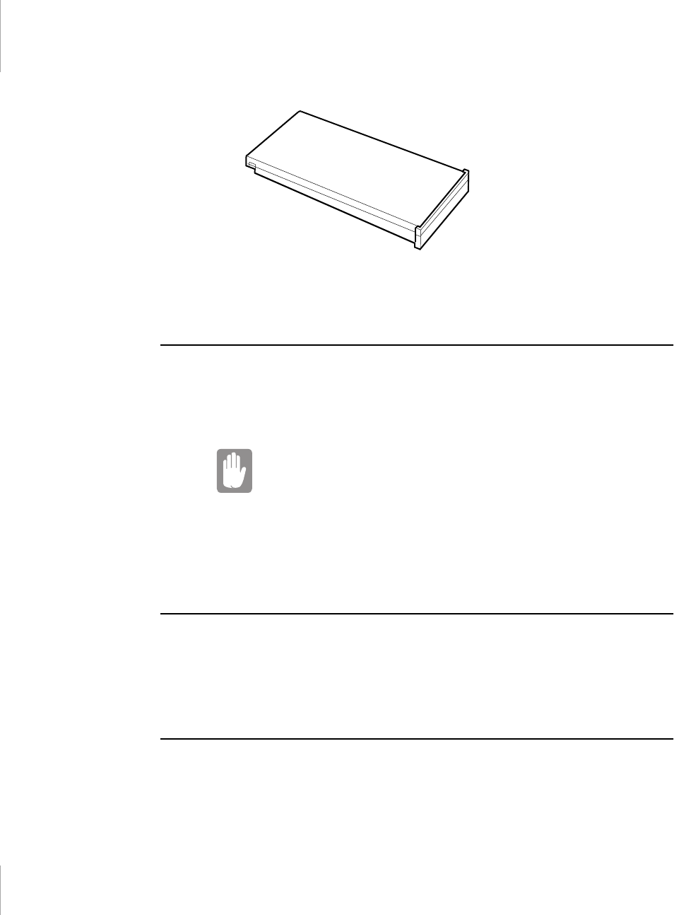
Using Options 79
Figure 24. Smart Lithium-ion Battery
Memory Modules
You can increase system memory by installing an optional memory module. You
computer comes with a non-removable 32 MB SDRAM SODIMM module and
can be upgraded by installing 32, 64 or 128 MB SDRAM SODIMM modules. The
maximum system memory is 160 MB.
Additional memory modules must only be installed by an
Authorised Reseller. To avoid possible system problems, use
only manufacturer-approved memory modules in your
computer.
Resellers, please refer to your Service Manual for memory installation
instructions.
External Numeric Keypad
The external numeric keypad has the same features as the integrated keypad. The
external keypad plugs into the PS/2 mouse and keyboard port. See ”Connecting
Peripheral Devices” on page 20
External CD-ROM Drive Module
The CD-ROM drive module can be connected to your computer using the external
module cable. See ”Connecting External Modules” on page 25 and see “Using the
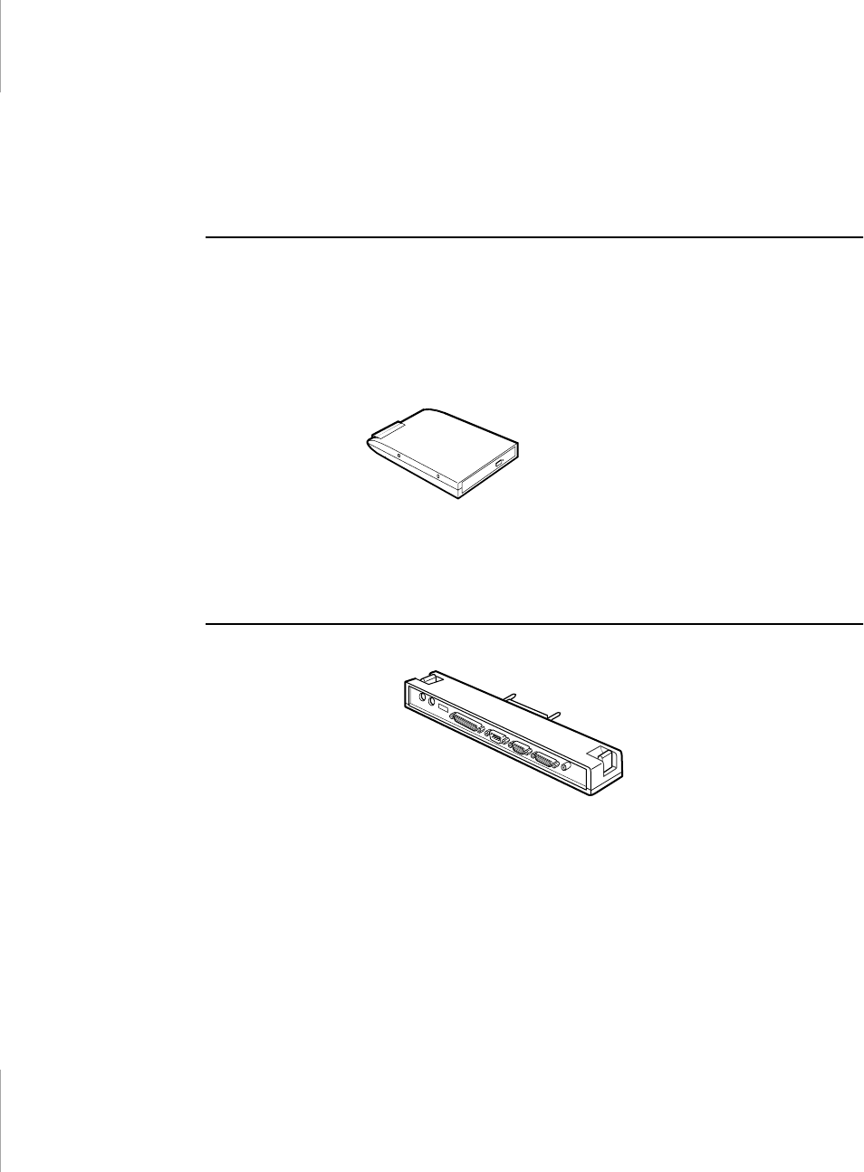
80 User’s Manual
CD-ROM Drive” on page 30 or directions on installing and using the CD-ROM
drive.
External DVD-ROM Drive Module
The external DVD-ROM drive module can be connected to your computer using
the external module cable. See ”Connecting External Modules” on page 25 and see
“Using the CD-ROM Drive” on page 30 or directions on installing and using the
DVD-ROM drive. There is MPEG2 software included with the drive that will
enable you to play DVD movies from the DVD-ROM drive.
Figure 25. External DVD-ROM Drive Module
Docking Options
You can order an additional Port Replicator.
Figure 26. Port Replicator
Contact your reseller for a list of other docking options available for your
computer. User’s manuals are included with the docking options.

Specifications 81
Specifications
Table 9 gives the specifications for your computer.
Table 9. System Specifications
Dimension
System with 12.1 TFT LCD
Width 11.7 in (297 mm)
Height 1.1 in (28 mm)
Depth 8.9 in (225 mm)
Weight (with battery installed) 4.2 lbs (1.9 kg)
LCD viewing area (12.1 TFT) 9.7 x 7.2 in (246 x 184.5 mm)
Environment
Ambient temperature, operating 41o–95o F (5o–35oC)
Ambient temperature, storage 14o–112o F (-10o–44o C)
Relative humidity (noncondensing),
operating
20–80%
Relative humidity (noncondensing),
storage
15–95%
Altitude, operating 0 to 8,000 ft (0 to 2,348 m)
Altitude, storage 0 to 40,000 ft (0 to 12,192 m)
Shock, operating 10 G for 11 ms half sine
Shock, nonoperating 60 G for 11 ms half sine

82 User’s Manual
Smart Lithium-Ion Battery
Weight 380g
Nominal open circuit voltage 10.8 Vcc
Capacity, typical 3200mAh
Charging time, approximate, with
computer turned off
2.5 hours
Charging time, approximate, with
computer turned on
4 hours
Average battery life, with power
management enabled
2.5 hours
AC Adapter
Width 2.05 in (5.2 cm)
Height 1 in (2.6 cm)
Length 4.33 in (11 cm)
Weight (0.21 kg)
Operating voltage 100-120 VAC/ 200-240 VAC
Line frequency 50/60 Hz
Input current 1.3 A 100 V - 0.7 A 240 V
Output current 2.63A
Output voltage 19V

Abbreviations 83
Abbreviations
Your documentation uses the following abbreviations:
A . . . . . . . . . Amperes
AC . . . . . . . . Alternating current
APM . . . . . . Advanced Power Management
ASK-IR . . . . Amplitude shift keyed infrared
ATA. . . . . . . AT attachment (refers to the hard-drive interface in an AT-
compatible computer)
BIOS . . . . . . Basic input/output system
C . . . . . . . . . Centigrade
CD . . . . . . . . Compact disc
CD-ROM . . Compact disc read-only memory
cm . . . . . . . . Centimeters
COM . . . . . . Communication (as in communication port)
CMOS . . . . . Complementary metal-oxide semiconductor
CMYK . . . . Cyan-Magenta-Yellow-blacK
DC . . . . . . . . Direct current
dBA . . . . . . . Decibels acoustic
DIN . . . . . . . Deutsche Industrie Normenuasschuss (German electrical standards
association)
DMA . . . . . . Direct memory access
DPMS . . . . . Display power-management signaling
DRAM. . . . . Dynamic random access memory
ECP . . . . . . . Extended capabilities port
EPP . . . . . . . Enhanced parallel port
F. . . . . . . . . . Fahrenheit
FIR . . . . . . . Fast infrared
ft . . . . . . . . . Feet
g. . . . . . . . . . gram
G . . . . . . . . . Gravity
GB . . . . . . . . Gigabytes

84 User’s Manual
hr. . . . . . . . . hour
Hz . . . . . . . . Hertz
IDE . . . . . . . Integrated drive electronics
in . . . . . . . . . Inches
I/O . . . . . . . . Input/Output
IrDA . . . . . . Infrared Data Association
IRQ . . . . . . . Interrupt request line
Kb/sec . . . . . Kilobits per second
KB . . . . . . . . Kilobytes
kg. . . . . . . . . Kilograms
LAN. . . . . . . Local-area network
lbs . . . . . . . . Pounds
LBA . . . . . . . Logical block addressing
LCD. . . . . . . Liquid-crystal display
m . . . . . . . . . Meters
mA. . . . . . . . Milliampere
mAhr . . . . . . Milliampere hour
MB. . . . . . . . Megabyte
Mb/sec. . . . . Megabits per second
MHz . . . . . . Megahertz
MIDI . . . . . . Musical instrument digital interface
mm . . . . . . . millimeter
MPU . . . . . . Microprocessor unit
ms . . . . . . . . Millisecond
PDF . . . . . . . Portable document format
PC . . . . . . . . Personal computer
PCI . . . . . . . Peripheral component interconnect
PCMCIA. . . Personal Computer Memory Card International Association
POST. . . . . . Power-on self-test
PS/2 . . . . . . . Personal System/2
RAM . . . . . . Random-access memory
RGB . . . . . . Red-Green-Blue
ROM . . . . . . Read-only memory

Abbreviations 85
SDRAM . . . Synchronous dynamic random-access memory
SMART. . . . Self-Monitoring, Analysis and Reporting Technology
SRAM . . . . . Static random-access memory
SVGA . . . . . Super video graphics array
TFT . . . . . . . Thin-film transistor
USB . . . . . . . Universal serial bus
V . . . . . . . . . Volt
VAC . . . . . . Voltage alternating current
VCC . . . . . . Voltage collector current
VDC . . . . . . Voltage direct current
VGA . . . . . . Video graphics array
whr . . . . . . . Watt hour
XGA . . . . . . Extended graphics array

86 User’s Manual
Glossary
AC adapter
The AC (or alternating current) adapter regulates current coming into your
computer from the wall outlet. The current at the wall outlet is alternating current
and needs to be changed by the adapter to DC (direct current) before your
computer can use it for power.
BIOS
BIOS stands for basic input/output system. The BIOS is software (often called
firmware) that is independent of any operating system. It enables the computer to
communicate with the screen, keyboard, and other peripheral devices without
using programs on the hard disk.
The BIOS on your computer is flash BIOS, which means that it has been recorded
on a flash memory chip that can be updated if needed.
Boot
To start your computer. A cold boot resets the entire computer and runs through
all computer self-tests. A warm boot clears out computer memory only.
Boot disk
A disk containing operating system programs required to start your computer. A
boot disk can be a floppy disk, hard drive, or compact disc.
Byte
The basic unit of measure for computer memory. A character—such as a letter of
the alphabet—uses one byte of memory. Computer memory is often measured in
kilobytes (1,024 bytes) or megabytes (1,048,576 bytes).
Each byte is made up of eight bits. For more information on bytes and bits, see an
introductory book on computers.
Cache memory
Cache is very fast, zero-wait-state memory located between the microprocessor
and main memory. Cache reduces the average time required for the
microprocessor to get the data it needs from the main memory by storing recently
accessed data in the cache.

Glossary 87
CardBus
CardBus technology enables the computer to use 32-bit PC Cards. Hardware in
the computer and the Windows 98 operating system provide support for the 32-
bit cards. The voltage of 32-bit cards (3.3 volts) is lower than that of 16-bit cards
(5 volts). The 32-bit cards can transmit more data at a time than the 16-bit cards,
thus increasing their speed.
CMOS memory
CMOS (complementary metal oxide semiconductor) memory is powered by the
CMOS battery. The System Setup settings and other parameters are maintained in
CMOS memory. Even when you turn your computer off, the information in
CMOS memory is saved.
COM port
COM stands for communication. COM ports are the serial ports in your computer.
Conventional memory
The first 640 KB of system memory. Operating systems and application programs
can directly access this memory without using memory-management software.
CMYK
A color model in which all colors are described as a mixture of four process colors
- Cyan, Magenta, Yellow and Black. CMYK is the standard color model used in
offset printing for full-color documents. Printed colors look the same as what
appears on the screen.
Disc
A compact disc (CD).
Disk
The device used by the computer to store and retrieve information. Disk can refer
to a floppy disk, hard disk, or RAM disk.
Disk cache
A software device that accumulates copies of recently used disk sectors in RAM.
The application program can then read these copies without accessing the disk.
This, in turn, speeds up the performance of the application.
A cache is a buffer for transferring disk sectors in and out of RAM. Data stored in
a disk cache is a copy of data already stored on the physical disk.

88 User’s Manual
DMA (direct memory access)
A method of transferring data from a device to memory without having the data
pass through the microprocessor. Using DMA can speed up system performance.
Floppy disk
A removable disk, also called floppy or diskette.
Hard drive
Also called fixed disk. A hard drive is connected to the computer and can be
installed or removed. Data written to a hard drive remains until it is overwritten
or corrupted.
The 2.5-inch hard drive in your computer was designed for use in a portable
computer. Because hard drives in portable computers are smaller than those in
desktop computers, their maximum storage capacity may be less than that of
desktop hard drives. However, because of their smaller size, the drives handle
shock and vibration better than larger drives, which is important for a portable
computer.
I/O
Input/output. Refers to peripheral devices, such as printers, that are addressed
through an I/O address.
I/O address
I/O stands for input/output. Peripheral devices, such as printers, are addressed
through the I/O port address.
IRQ (interrupt request line)
The IRQ is a hardware line that a device uses to signal the microprocessor when
the device needs the microprocessor’s services. The number of IRQs is limited by
industry standards.
LCD (liquid-crystal display)
The LCD screen on your computer differs from the display screen of a desktop
monitor. Most desktop monitors use CRT (cathode-ray tube) displays, which
work by moving an electron beam across phosphor dots on the back of the screen.
The phosphor dots light up to show the image. LCDs use a liquid-crystal solution
between two sheets of polarizing material. Electric current passing through the
liquid aligns the crystals so that light can or cannot pass through them, creating an
image.
MB
1,024 kilobytes.

Glossary 89
Megabit
1,048,576 bits or about 128 kilobytes.
Operating system
A program that supervises the computer's operation, including handling I/O.
Application programs and users can request operating-system services. A user
might request operation-system services to copy files or format a disk. An
application program might use the operating system to obtain keyboard input,
write data to a file, or write data to a screen.
PC Card
PC Card stands for personal computer card. The Personal Computer Memory
Card International Association (PCMCIA) defines the standards used to develop
all PC Cards. PC Card types include: modems, Ethernet adapters, SCSI adapters,
ATA cards, and memory cards.
PC slot
The PC slot is the hardware slot in the computer where the PC Card is placed.
Pixel
A pixel is an individual dot in a graphic displayed on your computer. The pixels
are so close together that they look as though they are connected. An LCD screen
displays thousands or millions of pixels.
Plug and Play
A plug and play operating system automatically configures computer components
to work with your system. With this type of operating system, you normally do
not need to set jumpers on devices or set memory addresses or IRQs.
POST
POST stands for power-on self-test. POST is a test performed by the computer
whenever you turn on the power. POST checks system integrity.
RAM (random access memory)
The computer's system memory, including conventional and extended memory.
You can write to and read from RAM. Information stored in RAM is temporary,
and is erased when the system is turned off.
Refresh rate
The refresh rate is the rate at which the image on the LCD screen is rewritten to
the screen. A fast refresh rate helps keep the image from flickering.

90 User’s Manual
Resolution
The resolution is the sharpness or clarity of the image on your LCD screen.
Resolution is measured by the number of pixels the computer’s screen can
display. For example, a resolution of 800x600 means that the screen can display
800 pixels in row and can display 600 rows. The more pixels displayed, the higher
the resolution and the better the image.
ROM (read-only memory)
Permanent computer memory dedicated to a particular function. For example, the
instructions for starting the computer when you first turn on power are contained
in ROM. You cannot write to ROM. (ROM is not the same as RAM).
Sector
Also known as disk sector. The portion of a track that is numbered and can hold
a specified number of characters (usually 512 KB).
Shadow RAM
A write-protected area of RAM that contains a copy of the BIOS. As the computer
boots, the BIOS is copied from its permanent location in ROM to RAM. The
BIOS can be executed much faster in RAM than in ROM. The BIOS remains in
shadow RAM until you turn off the computer.
RGB
A color model generally used by display devices. Colors are described as a
mixture of Red, Green and Blue.
TFT (thin film transistor) LCD
A TFT LCD uses a separate transistor circuit to control each pixel. This
technology provides the best resolution for an LCD screen. A TFT LCD is also
sometimes called an active matrix LCD.
Zoomed video
Zoomed video technology enables zoom video PC Card to transfer data directly
from the card to video and audio systems without going through the
microprocessor. This process improves video performance. Video conferencing
and real-time multimedia devices, such as video cameras, are supported by zoom
video.

Recording the Computer Hardware Configuration 91
Recording the Computer Hardware
Configuration
In the spaces provided, write the System Setup program settings. If your computer
ever loses configuration information, you can enter the information from this
section into System Setup to restore it.
MAIN MENU
Legacy Diskette A: Disabled 1.44 MB 3½
IDE ADAPTER1 SUBMENU
IDE Adapter1:
Type:___________ Cylinders:__________
Heads:__________ Sectors:____________
Multi-Sector Transfers:________
LBA Mode Control: Enabled Disabled
32 Bit I/O: Enabled Disabled
Transfer Mode: Standard
Fast PIO 1 Fast PIO 2
Fast PIO 3 Fast PIO 4
FPIO 3 / DMA 1 FPIO 4 / DMA 2
Ultra DMA: Mode 0 Mode 1
Mode 2 Disabled
IDE ADAPTER2 SUBMENU
IDE Adapter2:
Type:___________ Cylinders:__________
Heads:__________ Sectors:____________
Multi-Sector Transfers:________
LBA Mode Control: Enabled Disabled
32 Bit I/O: Enabled Disabled

92 User’s Manual
Transfer Mode: Standard
Fast PIO 1 Fast PIO 2
Fast PIO 3 Fast PIO 4
FPIO 3 / DMA 1 FPIO 4 / DMA 2
Ultra DMA: Mode 0 Mode 1
Mode 2 Disabled
MEMORY CACHE SUBMENU
Memory Cache: Enabled Disabled
Cache Extended Memory Area: Write Back Uncached
Write Through Write Protect
Cache D400 -D7FF Disabled Write Through
Write Protect Write Back
Cache D800 -DBFF Disabled Write Through
Write Protect Write Back
ADVANCED MENU
PS/2 MOUSE CONFIGURATION SUBMENU
Mouse Configuration: Enabled Disabled
Mouse Operation Mode: Single Mouse Dual Mouse
I/O DEVICE CONFIGURATION SUBMENU
Serial port A: Enabled Disabled Auto
Base I/O address: 3F8, IRQ 4 2F8, IRQ 3
3E8, IRQ 4 2E8, IRQ 3
Serial port B: Enabled Disabled
Base I/O address: 3F8, IRQ 4 2F8, IRQ 3
3E8, IRQ 4 2E8, IRQ 3
Mode: FIR Normal IrDA ASK-IR

Recording the Computer Hardware Configuration 93
DMA Channel: DMA 1 DMA 3
Parallel port: Enabled Disabled Auto
Mode: Bi-directional Output only
EPP ECP
Base I/O address: 378, IRQ 7 378, IRQ 5
278, IRQ 7 278, IRQ 5
3BC, IRQ 7 3BC, IRQ 5
DMA Channel: DMA 1 DMA 2 DMA 3
Floppy Disk Controller: Enabled Disabled Auto
Installed O/S: Win95/Win98 APM Other
Win98 ACPI/WinNT5.0
Boot-time Logo Screen: Enabled Disabled
QuickBoot Mode: Enabled Disabled
CPU BIOS Update: Enabled Disabled
USB Device: Enabled Disabled
Screen Expansion: Enabled Disabled
TV Standard: NTSC PAL PAL-M
PAL-60 NTSC-J SCART-PAL
Local Bus IDE adapter: Both Disabled
Primary Secondary
Large Disk Access Mode: DOS Other

94 User’s Manual
SECURITY MENU
Password on boot: Enabled Disabled
Fixed disk boot sector: Normal Write Protect
Diskette access: User Supervisor
Virus check reminder: Daily Weekly Monthly
Disabled
System backup reminder: Daily Weekly Monthly
Disabled
POWER MENU
Power Savings Mode: Max. Power Savings Max. Performance
Standby Timeout: Off Time_________________
Rest Mode: Power On Suspend Save To Disk
Rest Timeout: Off Time_________________
Resume On Time: On Off
Resume Time:________________________
BOOT MENU
Floppy Check: Enabled Disabled
Summary Screen: Enabled Disabled
BOOT DEVICE PRIORITY SUBMENU
Boot option 1:________________________
Boot option 2:________________________
Boot option 3:________________________