Samsung Electronics Co S820 Notebook Computer User Manual MANUAL
Samsung Electronics Co Ltd Notebook Computer MANUAL
UserManual.wiki
>
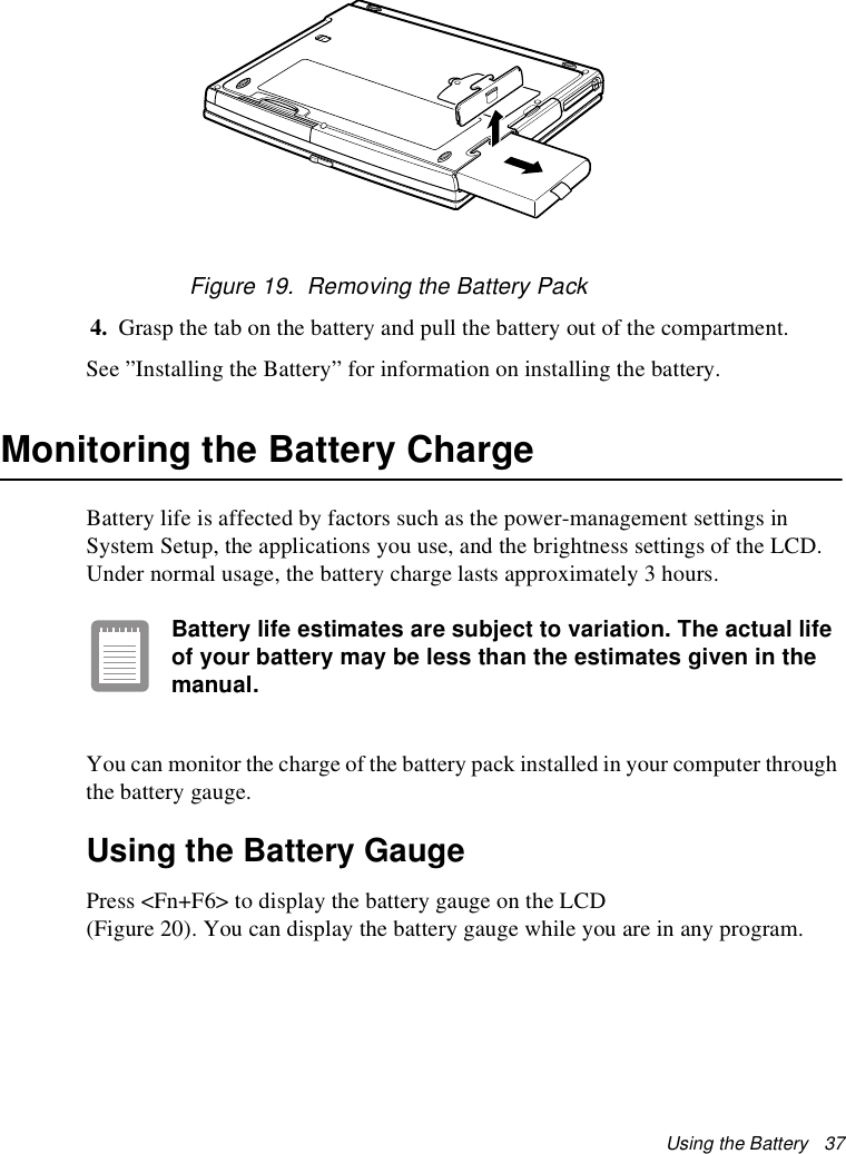
Samsung Electronics Co
>
S820 User Manual
MANUAL
Navigation menu
Upload a User Manual
Namespaces
Wiki Guide
HTML
PDF
Info
Views
User Manual
Discussion / Help
Navigation
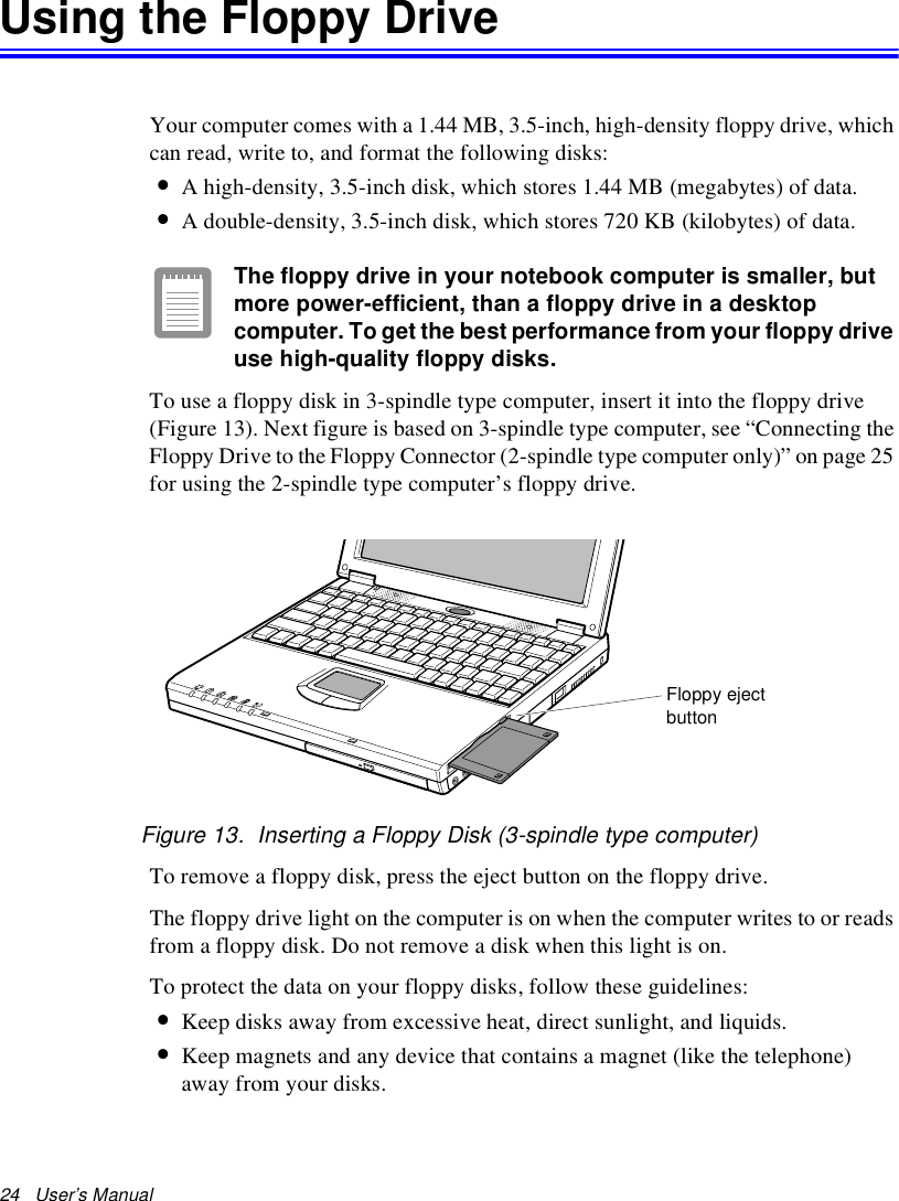
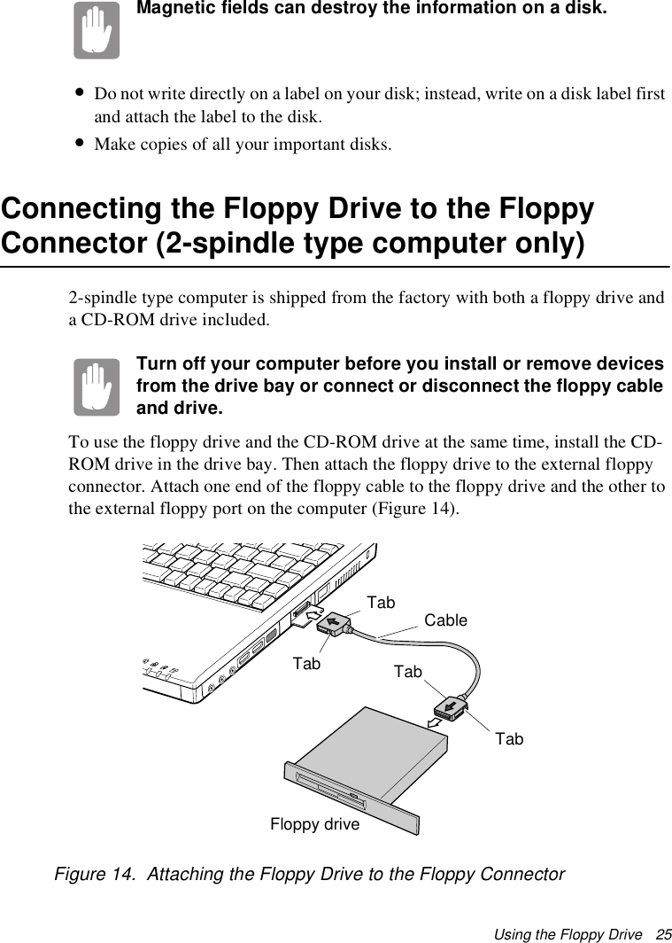
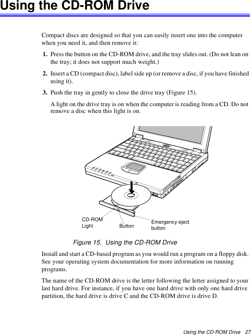
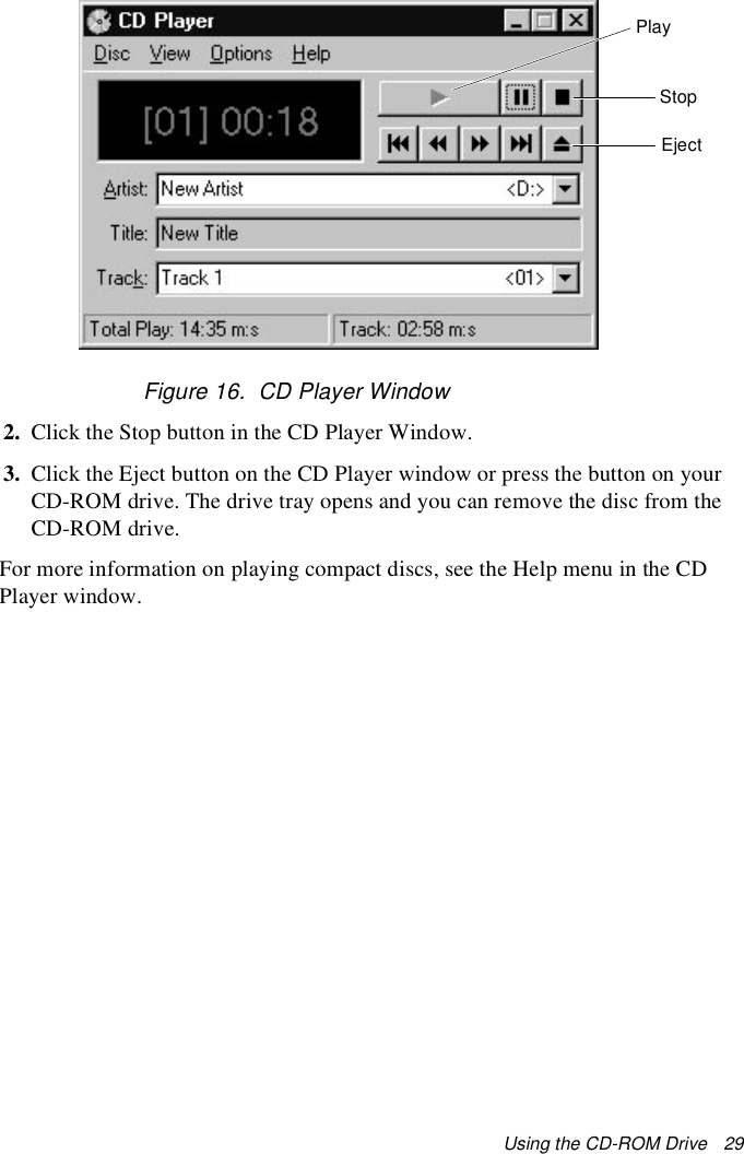
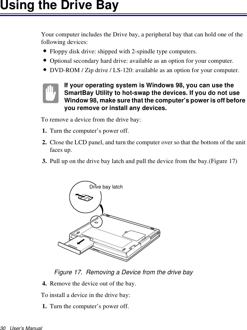
![68 User’s Manual 7. To change the resolution, click and drag the knob under the Screen area until you select the resolution you want.8. Click the OK button.9. Follow the prompts that appear on the screen.Changing the Video DriverIt is possible that you may want to update your video driver or that your installed video driver has become corrupt so that the display is unusable.In Windows 98:1. Click on the Start Button. The Start Menu appears.2. Select Settings and click on Control Panel, double click on Display. The Display Properties window appears.3. Click the Advanced button. The properties screen for your currently installed video driver appears4. Select the Adapter menu.5. Click the Change button. The Update Device Driver Wizard window appears.6. Click the Next button. 7. Select Display a list of all the drivers in a specific location, so you can select the driver you want. Click the Next button.8. Click the Have disk button. If the driver is on a floppy disk insert it into the floppy drive or if you want to use the origianl factory driver insert the Restore CD-ROM into the CD-ROM drive. Click the Browse button and locate driver you want to install. Click the OK button.9. Select the new driver in the Select Device screen and click the Ok button.10. Click the Next button to install the new driver and follow any directions on the screen to finish setting the display properties.In Windows NT 4.0:1. As the computer starts, select Windows NT Workstation Version 4.00 [VGA mode] as the operating system and press <Enter>.](https://usermanual.wiki/Samsung-Electronics-Co/S820/User-Guide-24010-Page-51.png)