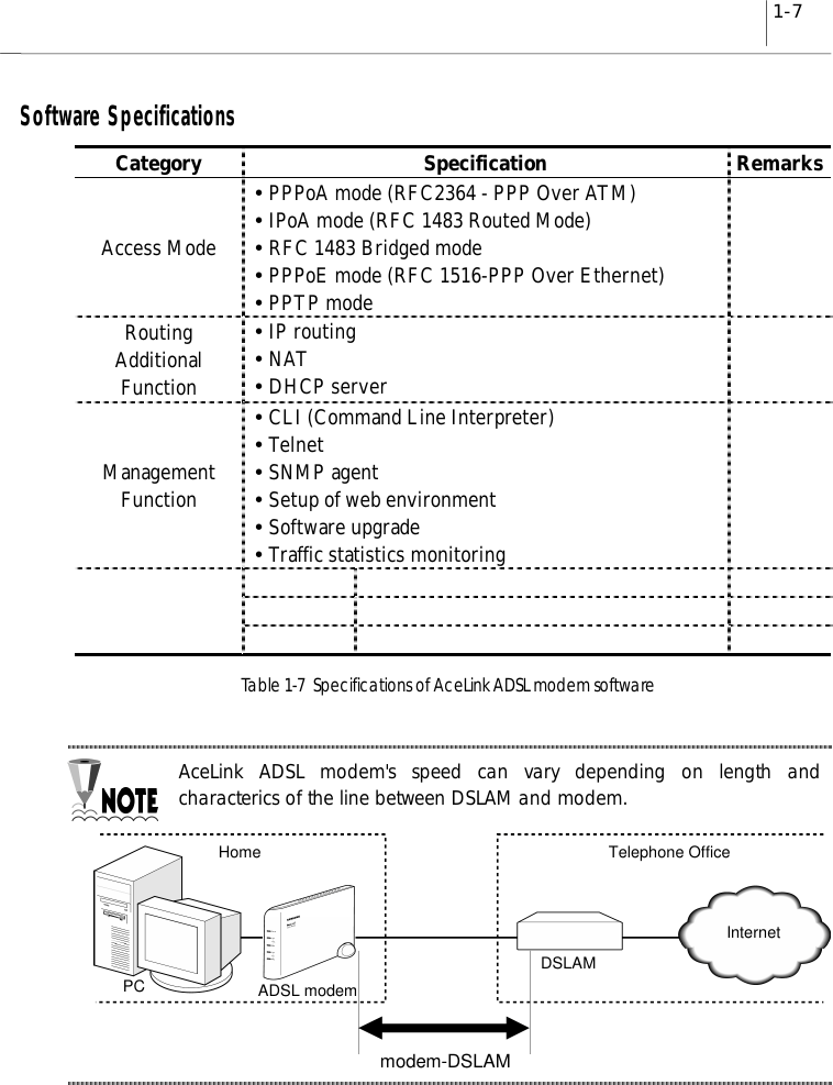
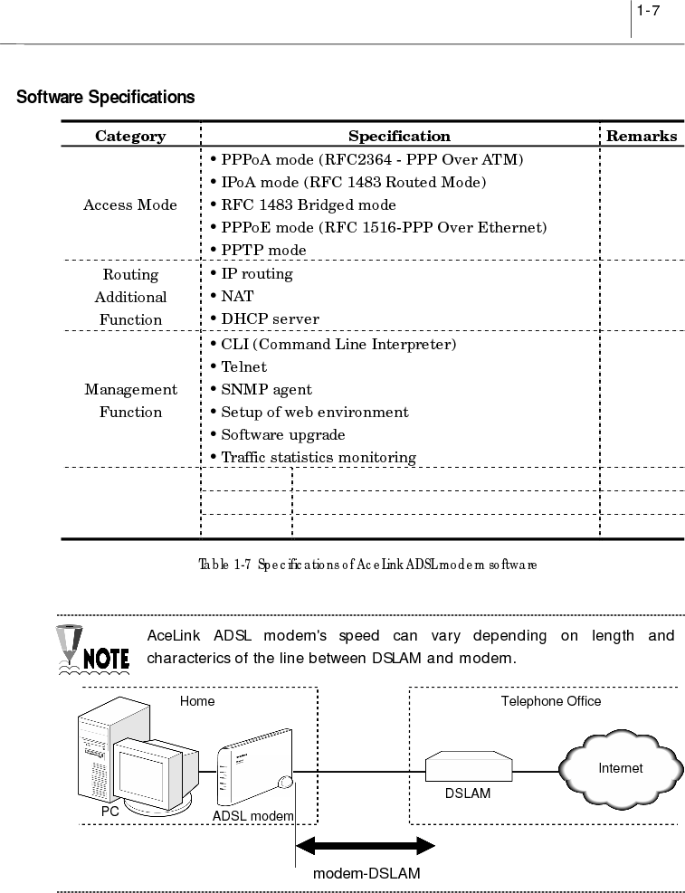
Samsung Electronics Co SAM335 ADSL Modem User Manual

Samsung Electronics Co Ltd ADSL Modem

User manual

English
iiiClass B Digital Device or PeripheralThis equipment has been tested and found to comply with the limits for a Class B digitaldevice, pursuant to Part 15 of the FCC Rules. These limits are designed to providereasonable protection against harmful interference in a residential installation. Thisequipment generates, uses and can radiate radio frequency energy and, if not installedand used in accordance with the instructions, may cause harmful interference to radiocommunications. However, there is no guarantee that interference will not occur in aparticular installation. If this equipment does cause harmful interference to radio ortelevision reception, which can be determined by turning the equipment off and on, theuser is encouraged to try to correct the interference by one or more of the followingmeasures:-Reorient or relocate the receiving antenna.-Increase the separation between the equipment and receiver.-Connect the equipment into an outlet on a circuit different from that to which thereceiver is connected.-Consult the dealer or experienced radio TV technician for help.Before StartingThis manual is for AceLink ADSL modem users. This book includes from theintroduction to installation, and problem solutions.We recommend that the user read this guide carefully before operation of equipment.If already familiar with the ADSL modem or similar systems, please read the notices inthe explanations for review.If you encounter any problems or have any questions, please contact the serviceprovider.CAUTION: Changes or modifications not expressly approved by the manufacturerresponsible for compliance could void the user's authority to operate the equipment
ivAbout ManualFollowing contents are described in each chapter of AceLink ADSL modem manual.Chapter 1 ‘Introduction’ describes the main functions of the AceLink ADSL modem,as well as its applications, hardware structure, and specificationsChapter 2 ‘AceLink ADSL Modem Setup’ examines what the user must knowbefore installation, and describes the AceLink ADSL modem settingenvironment and connection to network.Appendix A ‘Troubleshooting’ describes major problems in using the AceLink ADSLmodem, and solutions.Appendix B ‘Cable Specifications’ describes every sort of cable specification that isneeded for installation of AceLink ADSL modem.Appendix C ‘Description of Terms’ explains terminology that you need to knowduring the use of AceLink ADSL modem.
vContentsChapter 1 Introduction ...............................................1-1~1-7Introduction to AceLink ADSL modem ................................................1-2Name and Function of each part...........................................................1-3Front View................................................................................................. 1-3Rear View..................................................................................................1-4AceLink ADSL modem specifications...................................................1-5Software Specifications............................................................................... 1-7Chapter 2 AceLink ADSL Modem Setup.....................2-1~2-13Before Installation ................................................................................. 2-2Safety Check............................................................................................. 2-2Service Environment Check.................................................................... 2-3Preparing cables.....................................................................................2-4Modem Setting Environment................................................................... 2-6Checking the Contents...........................................................................2-7Modem Setup .........................................................................................2-81. Drawing the Network Configuration.................................................... 2-92. Power Disconnection.......................................................................... 2-103. Connecting Ethernet Cables.............................................................. 2-104. POTS Micro-filter Connection........................................................... 2-115. Power Connection............................................................................... 2-126. Checking all the Connections............................................................. 2-13Appendix A Troubleshooting.........................................A-1~A-3Points You Must Know before Inquiring at the Place WhereYou Purchased........................................................................................A-1Troubleshooting - Problems and Solution .............................................A-2Appendix B Cable Specifications...................................B-1~B-3Twisted pair Category-3,4,5 Straight-through Ethernet Cable...............B-1Telephone Cable (RJ-11)...........................................................................B-3Appendix C Description of Terms.................................. C-1~C-4
viFigure ContentsFigure 1-1  Front view of AceLink ADSL modem.............................................................. 1-3Figure 1-2  Rear view of AceLink ADSL modem................................................................ 1-4Figure 2-1  RJ-11 telephone cable........................................................................................ 2-5Figure 2-2  RJ-45 UTP Ethernet Cable ...............................................................................2-5Figure 2-3  AceLink modem package.................................................................................. 2-7Figure 2-4  Example of network configuration.................................................................... 2-9Figure 2-5  Ethernet Cable Connection............................................................................. 2-10Figure 2-6  POTS micro-filter connection.........................................................................2-11Figure 2-7  Power adapter connection...............................................................................2-12Figure B-1  Twisted pair Category-3,4,5 Straight-through cable.......................................B-1Figure B-2  Twisted pair Category-3,4,5 Straight-through cable connector signal...........B-2Figure B-3  Pin connection of Twisted pair Category-3,4,5 Straight-throughcable connector .................................................................................................B-2Figure B-4  RJ-11 telephone cable.......................................................................................B-3
viiTable ContentsTable 1-1  AceLink ADSL modem's LED functions............................................................ 1-3Table 1-2  AceLink ADSL modem's port functions............................................................. 1-4Table 1-3  Hardware specifications of AceLink ADSL modem ..........................................1-5Table 1-4  DMT specifications of AceLink ADSL modem..................................................1-6Table 1-5  Specifications of external connector of AceLink ADSL modem.......................1-6Table 1-6  Specifications of external connector of AceLink ADSL modem.......................1-6Table 1-7  Specifications of AceLink ADSL modem software............................................ 1-7Table B-1  Pin connection of RJ-11 telephone cable connector..........................................B-3
1-1Chapter 1IntroductionThis chapter describes the main functions of the AceLink ADSL modem, as well as itsapplications, hardware structure, and specifications.yIntroduction to the AceLink ADSL modemyName and function of each componentyAceLink ADSL modem specifications
1-2 Chapter 1IntroductionIntroduction to AceLink ADSL modemIt is possible to access the Internet and other multimedia service networks through anexisting telephone line (PSTN) using AceLink ADSL modem.Unlike previous dial-up modems, AceLink ADSL modems provide the fastest speedavailable as well as allow use of the telephone at the same time.Characteristics of AceLink ADSL modem;Various ApplicationsSome of the applications of AceLink ADSL modem include Internet access, chatting(real-time communication), file transfers, and data download/upload.Inexpensive PriceAceLink ADSL modem uses a pre-existing phone line (PSTN) instead of using aseparate cable, which needs a great amount of money and time to install.Reliable Network ConnectionAceLink ADSL modem operates in connection with the master system in the localtelephone office letting the telephone office manage all of the networking services.Easy InstallationAceLink ADSL modem is easy install so that a popular user can easily connect to ISPand receive the internet service.Web-based ManagementAceLink ADSL modem provides a web environment management function. Whereby,the user can monitor the modem’s state and change the settings easily.
1-3Name and Function of each partFront ViewFigure 1-1  Front view of AceLink ADSL modemNumber Label Color Function❶Power Green On, while AC power is provided.❷Link(ADSL) Green On, while connected to telephone office’s ADSL mastersystem.❸Data(ADSL) Green Flashing, when sending/receiving to/from telephoneoffice’s ADSL master system.❹Link(User) Green On, while connected to PC.❺Data(User) Green Flashing, when sending/receiving data through PC.Table 1-1  AceLink ADSL modem's LED functions
1-4 Chapter 1IntroductionRear ViewFigure 1-2  Rear view of AceLink ADSL modemNumber Label Port Function❶Off / On Power Switch A power switch of AceLink ADSL Modem.❷ADSL ADSL lineportConnect RJ-11 telephone line from the telephonesocket on the wall. This port is used to send/receiveADSL data.❸Phone Telephoneport Connected to ordinary telephone through micro-filter.❹DC 5V Power inputport A jack to connect Input power (AC 110V, DC 5Vadapter) to ADSL modem.❺Console Serial port(RS232C) Used for maintenance of ADSL by technician.❻Ethernet Ethernet port Connect to PC’s network adapter by using UTP.Category-3,4,5 Straight-through cable. Provide up to10Mbps speed.Table 1-2  AceLink ADSL modem's port functions
1-5AceLink ADSL modem specificationsHardware FeaturesCategory SpecificationPower Supplyof Main Boardy Input Power : DC 5V (5V/1.5A)y Voltage usable : 3.3V and 12Vy Power consumed : 4.5Watts (Max)Power SupplyAdaptery Rated Input : AC 110V, 60Hzy Rated Output : DC +5.0V 1.5AUser Interfacey ADSL Interface(RJ-11) : Telephone liney Telephone Interface(RJ-11) : Telephoney Ethernet Interface(RJ-45) : Connection to 10Mbps Ethernet Port(Straight-through)y Console Interface(DB-9:Female) : 19,600bps Null modem interfaceLEDy Power : A green light is on during normal operation of the modem.y Link (ADSL) : A green light is on when it is linked to ADSL homesystem network.y Data (ADSL) : A green light flickers during transmitting/receiving ofdata with ADSL home system network.y Link (User) : A green light is on when it is linked to Ethernet portof PC.y Data (User) : A green light is on during transmitting/receiving ofdata with PC.Packagey Package Material : Plasticy Dimension : 37(width) x 233(length) x 164.2(height) mmy Weight : 1 Kg (modem, power supply device and cables areincluded)y Installation : Vertical installation is available (an installation rack isprovided).Table 1-3  Hardware specifications of AceLink ADSL modem
1-6 Chapter 1IntroductionDMT SpecificationsCategory Down Stream Up stream RemarksMax Data Rate 8Mbps 640Kbps접속 DSLAM 및전송거리에 따라 차이가 있을수 있습니다.ADSL OverHead 96Kbps 32Kbps Frame Mode 3Bandwidth 0.11Mhz ~ 1.1Mhz 30Khz ~ 110KhzTX Power 20dBm 12dBmBin Width 4.3125Khz T1.413 standard(+/-50ppm)Max Sym/bin 16 BitLatency Fast channel : < 2ms, Interleaved < 20msApplied Standard ANSI/T1.413, ITU-T/G.992.1, ITU-T/G.992.2Table 1-4  DMT specifications of AceLink ADSL modemExternal Connector SpecificationsType Options RemarksRJ-45 Ethernet y Internet access available by connecting to externalPCRJ-11 TelephoneLiney Telephone access available through external micro-filterRJ-11 ADSL Line y Connected to external ADSL linePower Jack y AC/DC converter 5V adapterPower Switch y Power On/Off switchTable 1-5  Specifications of external connector of AceLink ADSL modemOther SpecificationsContent Item RemarksWorking Temp. 0 ~ 45℃Telephone Service Linked to telephone using external micro-filterForeign Standard Form approval(EMI CLASS B)U.S. FCC Part 15 & 68Table 1-6  Specifications of external connector of AceLink ADSL modem
1-7Software SpecificationsCategory Specification RemarksAccess Modey PPPoA mode (RFC2364 - PPP Over ATM)y IPoA mode (RFC 1483 Routed Mode)y RFC 1483 Bridged modey PPPoE mode (RFC 1516-PPP Over Ethernet)y PPTP modeRoutingAdditionalFunctiony IP routingy NATy DHCP serverManagementFunctiony CLI (Command Line Interpreter)y Telnety SNMP agenty Setup of web environmenty Software upgradey Traffic statistics monitoringTable 1-7  Specifications of AceLink ADSL modem softwareAceLink ADSL modem's speed can vary depending on length andcharacterics of the line between DSLAM and modem.Home Telephone OfficePC ADSL modemDSLAMInternetmodem-DSLAM
2-1Chapter 2AceLink ADSL Modem SetupThis chapter introduces the environment where AceLink ADSL modem can be installedand explains how to install this product and link it to a network.This chapter consists of the following contents.yBefore installationyChecking the ContentsyModem Setup
2-2 Chapter 2AceLink ADSL Modem SetupBefore InstallationThis chapter examines what the user must know before installation.Before installation of your ADSL modem follow the directions described in this chapter.Safety CheckBefore proceeding with the installation of the AceLink ADSL modem, user must checkthe following categories.Electricity Safety checkyThe user should not remove or open the product’s cover, it is especially dangerouswhen the power is on.yCheck and make sure if there are any flammable, electric conducting objects aroundthe modem. Make sure that there are no wet objects around. And check if the cable isnot worn out and other electrical devices around the modem are properly grounded.Location checkyElectrical products tend to generate heat during operation. It is possible that if theenvironment does not provide enough ventilation it would result in improper functionof the modem. Make sure that the modem is exposed to circulating air.yCheck if the power is properly provided. If it happens to cause sparks or noise, be sureto install a voltage regulator.
2-3Service Environment CheckCheck the followings before installing your AceLink ADSL modem.Telephone network serviceThe AceLink ADSL modem should be installed where telephone networkservice is available.If there is no telephone line available in your area, be sure to report to the localtelephone office to construct a telephone line.The telephone network service must support ADSL modem connection.Some of the telephone network services will support ADSL applications. Check withyour local telephone office for subscription of ADSL.PC Specification CheckIn order to use AceLink ADSL modem by connecting to a PC, a LAN card (10Base-T or10/100Base-T network adapter) must be installed in your PC. You can purchase the LANcard at any PC shop.Using the USB port on the SAM-335U model requires a higher versionoperating system than Windows 98 SE (Second Edition).
2-4 Chapter 2AceLink ADSL Modem SetupPreparing cablesYou must have all cables ready before connecting to the network. The following cablesare needed to connect the AceLink ADSL modem to the network.Port Required cableTelephone line port (PHONE) RJ-11 telephone cables.Ethernet port (10BASE-T) RJ-45 UTP Category-3,4,5 Straight-through cable.Table 2-1  Cables used by AceLink ADSL modemA console port connection cable is not provided with the product.
2-5RJ-11 telephone cableOne end of the RJ-11 telephone cable is connected to telephone line port (phone) in theback of the AceLink ADSL modem, and the other is connected to the POTS micro-filter(LINE) which is provided separately.Figure 2-1  RJ-11 telephone cableRJ-45 UTP Ethernet cableConnect one end of the RJ-45 UTP Ethernet cable to the Ethernet port (10BASE-T)which is at the rear plane of AceLink ADSL modem and connect the other end to theLAN card of the PC.Figure 2-2  RJ-45 UTP Ethernet CableCables may look alike, however they could be different, for example theycould have different inner pins. Therefore, in order not to use them withother cables, it is recommended to label each cable.
2-6 Chapter 2AceLink ADSL Modem SetupModem Setting EnvironmentFor safe installation, let’s examine the AceLink ADSL modem setting environment.The AceLink ADSL modem should be kept at moderate temperature and humidity.The recommended environment is as follows:y Temperature : 0 ~ 45℃y Relative humidity : 10 ~ 90% (uncondensed)y Power : 4.5 Watts (maximum)y Input power : AC 110V, DC 5Vy Frequency : 60HzThe voltage variation of the power input during operation should be within5 % of regulatory voltage. The electrical outlet should be grounded. Also,the AceLink ADSL modem's power connecter should not be used on thesame outlet where a hair dryer, iron or refrigerator is connected. Toprovide a stable power supply, an AVR (Automatic Voltage Regulator) isrecommended to be used.
2-7Checking the ContentsAfter purchasing your AceLink ADSL modem package, open the box and check if all thefollowing contents are included.Figure 2-3  AceLink modem packageA POTS micro-filter is needed to use the ordinary telephone service andADSL data service at the same time. You need to prepare a POTS micro-filter for each telephone used in your home. Ask your AceLink ADSLmodem provider about purchasing additional POTS micro-filters.AceLink ADSL ModemPOTS Micro-filter 그림도 한 개로수정User GuidePower AdapterRJ-45 UTP Ethernet CableRJ-11 Telephone Cabel 그림도 한 개로 수정Y Jack
2-8 Chapter 2AceLink ADSL Modem SetupModem SetupWe will go over how to configure your AceLink ADSL modem.Configuration procedures are as follows :1. Drawing the network configuration2. Power disconnection3. Ethernet Cable connection4. POTS micro-filter connection5. Power connection6. Checking all the connectionsEach step is described in detail below.
2-91. Drawing the Network ConfigurationFirst, it is better to draw a network configuration for the AceLink ADSL modem. Youmust consider the following matters when drawing a network configuration.yWhat will the AceLink ADSL modem are used for?yAre you going to use the AceLink ADSL modem and telephone at the same time?yHave you prepared all the necessary equipment such as PC, POTS micro-filter,telephone, and network cable?The diagram below is an example configuration of an AceLink modem to PC, POTSmicro-filter and telephone. Draw your own configuration in reference with this diagram.Figure 2-4  Example of network configurationInternetPSTNSubscriber's home telephone networkPC AC 110V Telephone #2POTS Micro-filter #1RouterSwitch SystemAceLink ADSL system(DSLAM)LINELINE10Base-TADSL modemTelephone #1
2-10 Chapter 2AceLink ADSL Modem Setup2. Power DisconnectionIf power is supplied to the AceLink ADSL modem, be sure to pull out the power cordfrom the electrical outlet before connecting the modem to any other device.3. Connecting Ethernet CablesConnect one side of the RJ-45 UTP Ethernet cable to the AceLink ADSL modem’sEthernet port (Label:10BASE-T) and connect the other side to the network adapterinstalled in the PC.Figure 2-5  Ethernet Cable ConnectionIn order to connect the AceLink ADSL modem to a PC, the PC must have a10Mbps or 10/100 Mbps speed network adapter. For network adapterinstallation, refer to the manual provided with the network adapter.
2-114. POTS Micro-filter ConnectionConnect your AceLink ADSL modem to a telephone using a micro-filter by following theprocedures below.❶Pull out the telephone line currently in use from your wall jack and connect it to theAceLink ADSL modem’s ADSL port.❷With the provided RJ-11 telephone cable, connect one side to the POTS micro-filterLINE port, the other side to the AceLink ADSL modem’s Phone port.❸Connect RJ-11 telephone cable attached to POTS micro-filter to Y-jack port.❹Connect RJ-11 telephone cable from Y-jack port to telephone.❺Reverse-wire remaining Y-jack port.Figure 2-6  POTS micro-filter connectionPHONE portPHONE portLINE portADSL portReverse Wiring
2-12 Chapter 2AceLink ADSL Modem SetupIf more than two telephones are used, more POTS micro-filters are needed.Ask your AceLink ADSL modem provider to purchase additional POTSmicro-filters.If the telephone, used with AceLink ADSL modem, is not connected througha POTS micro-filter, telephone conversation quality will go down.5. Power ConnectionConnect power adapter to AceLink ADSL modem’s power input port (DC 5V). And then,connect power adapter to electrical outlet.Figure 2-7  Power adapter connectionInstallation of the AceLink ADSL modem has now been completed.The power adapter used with your ADSL modem must be the adapterprovided with your ADSL modem package.
2-136. Checking all the ConnectionsUse the following method to check all the connections.Checking ADSL Line connectionIf the ADSL Link LED blinks and then is keeping up ON within seconds of powerconnection, the ADSL line is properly connected.Checking PC connectionIf network adapter’s LINK LED and AceLink ADSL modem’s User Link LED are green,connection between PC and AceLink ADSL modem is properly established.Checking telephone line connectionIf you hear a normal signal on your telephone, and have clear reception without ghostvoices, the telephone line is properly connected.The AceLink ADSL modem's power source does not affect the use oftelephone
A-1Appendix A TroubleshootingIn appendix A, major problems in using the AceLink ADSL modem, and solutionsthereof will be described. Appendix A covers the following:yPoints you must know before inquiring at the place where you purchasedyTroubleshooting - Problems and SolutionsPoints You Must Know before Inquiring at the Place WhereYou PurchasedWhen a problem, which you cannot solve, occurs during use of the system, you willinevitably inquire at the place where you purchased it and have them assist you.Before you inquire at the place where you purchased the system, prepare a noteincluding the following product information :yProduct model name (e.g.: External AceLink ADSL Modem - Model name : SAM-335)yProduct serial numberyDate when product was purchasedyMemo about the problemyMemo about what you have sequentially done to solve the problem by yourself
A-2Appendix ATroubleshootingTroubleshooting - Problems and SolutionMany types of problems are proposed, and problems of each type that may happen aredescribed in detail with solutions to the problems.Types of Problem That May HappenThe following types of problems may frequently occur when using the AceLink ADSLmodem.yProblems related to poweryProblems related to network connectionProblems Related to PowerThe following problems related to power may occur.9Even when the power supply adapter is connected to the system and the powersupply cable connected to the power supply adapter is coupled to an electrical plugsocket, the Power LED is not lit green.When this problem occurs, check the following :ÂCheck that the electrical plug socket is working.ÂRemove the jack from the power input port (DC 5V) on the back of the AceLinkADSL modem. After about 10 seconds, connect the jack to the port again andrestart the AceLink ADSL modem.If the problem is not solved with the above method, remove the jack from the power-input port of AceLink ADSL modem and inquire at the place you purchased the product.
A-3Problems Related to Network ConnectionThe following problems related to network connection might occur.9The modem is not connected to the Internet.9User Link LED or ADSL Link LED is not light.When this problem occurs, check the following :ÂCheck the connection state of the cables connecting the AceLink ADSL modem,POTS micro-filter and PC.ÂCheck the state of the network adapter installed in the PC.ÂCheck the operating state of the PC.ÂCheck whether an IP address is set to meet the connection service provided.If the problem is not solved with the above method, remove the jack from the power-input port of AceLink ADSL modem and inquire through ISP(Internet Service Provider)or at the place you purchased the product.
B-1Appendix B Cable SpecificationsAppendix B explains the specifications of the cables connected to each port of AceLinkADSL modem, every connector signal, and pin connection.yEthernet CableyTelephone (RJ-11) CableTwisted pair Category-3,4,5 Straight-through Ethernet CableTwisted pair Category-3,4,5 Straight-through Ethernet is needed for connecting AceLinkADSL modem to the LAN card of a PC.Make sure to use Category-5 cable in case of connection with devices using100Mbps Fast Ethernet.Cable DiagramFigure B-1  Twisted pair Category-3,4,5 Straight-through cable
B-2Appendix BCable SpecificationsConnector SignalADSL Modem PCFigure B-2  Twisted pair Category-3,4,5 Straight-through cable connector signalPin Connection< Pin constitution > < Actual pin connection >Figure B-3  Pin connection of Twisted pair Category-3,4,5 Straight-through cable connector
B-3Telephone Cable (RJ-11)We will examine the RJ-ll telephone cable connector that is used as a connector betweenAceLink ADSL modem and a telephone line.Connect one end (RJ-11 jack) of the telephone cable to the telephone port at the back ofthe modem and the other end (RJ-11 jack) to the RJ-11 connector of the POTS micro-filter.Cable DiagramFigure B-4  RJ-11 telephone cablePin ConnectionRJ11 RJ111NC1NC2 (A)Tip 2 (A)Tip3 (B)Ring 3 (B)Ring4NC4NCTable B-1  Pin connection of RJ-11 telephone cable connector
C-1Appendix C Description of Terms10BASE-TAn Ethernet interface having a bandwidth, which provides a transmission rate, that maygo up to 10 Mbps using a Category 5 cable.ATU-C (ADSL Transceiver-Central Office)A central unit managed by an ISP(Internet Service Provider) for connection of ADSLsubscriber lines.ATU-R (ADSL Transceiver -Remote Terminal)A subscriber terminal which is connected to ATU-C through a telephone line, whichprocesses ADSL service.ADSL (Asymmetric Digital Subscriber Line)A device providing a high-speed data interface to the Internet, and other services,through a telephone network. This does not influence existing telephone service. 데이터 전송속도는 전송거리 및 ATU-C 및 서비스 종류에 따라 차이가 있으며 다운로드 속도는 640Kbps 에서 8Mbps, 업로드 속도는 16Kbps 에서 800Kbps 입니다..ATM (Asynchronous Transfer Mode)One of the communications transfer modes. A control mode in which a series ofterminals can simultaneously send data while a terminal is sending data, therebyallowing a series of terminals to share a single transmission line for communication.BridgeA functional unit interconnecting two or more local area networks (LANs) that uses thesame link protocol. The bridge not only transmits but also filters packets. The bridgeusually operates on a Data Link Layer when it transmits packets.DMT (Discrete Multi-Tone)A modulation technique of segmenting and transmitting a large amount of data by way ofMulti-carrier, in which a carrier frequency band is multiplexed, thereby realizing optimalperformance on a Loop.
C-2Appendix CDescription of TermsEthernetA representative method of interconnecting LANs was using a transmission cable of10BASE standard. Three companies, i.e., Xerox, Intel and DEC develop this method, incooperation. Its transmission rate is about 10 Mbps, and employs a CSMA/CD accessmethod in which a node monitors signals over a transmission line and sends data afterconfirming that the other nodes do not send signals.HubA communications interface used for interconnecting a series of devices on a network.This retransmits a signal, which is received from a device, or segments a received signaland transmits the segmented signal.FTP (File Transfer Protocol)A protocol for transferring files from one host to another or from a host to a personalcomputer over a network.GopherAn interface that has been used as the easiest interface before the WWW service wasdeveloped. The gopher constructs a menu by classifying the contents of information bytopic or type, thereby allowing even people, whom is not familiar with the Internet, toeasily search information. In addition, other functions of the Internet such as remoteaccess, file transfer, news, etc. can be performed in the gopher menu. A series of gopherservers are interconnected so that a user can search for desired information movingfrom one gopher server to another.IP (Internet Protocol) AddressAn address of a host or a device on the Internet. It is composed of 4 bytes. Each byte isdivided by a period. An IP address is assigned by IANA (Internet Assigned NumbersAuthority) to avoid duplication.PPPoA (Point-to-Point Protocol)The standard protocol for providing the serial interface between nodes, e.g., between aPC and a RAS or between routers, on the Internet. PPPoA provides an Internet accessrate, and is widely used substituting for a SLIP (Serial Line Internet Protocol) which is apreviously used serial interface protocol. PPPoA is designed to transmit various networkprotocols including IPX. PPPoA performs various and useful functions includingnegotiation of a receiving maximum packet size over a serial line.
C-3POTS (Plane Old Telephone Service) Micro filterA POTS micro filter separate a voice signal from a data signals not to influence anexisting telephone service. By separating PSTN using a POTS micro filter, networkservice such as Internet and telephone service can be simultaneously used.SwitchA network device for filtering and transmitting frames based on the destination addressof a frame. A switch operates at the Data Link Layer of the OSI-RM.TCP/IP (Transmission Control Protocol/Internet Protocol)One of the network protocols that are frequently used in a LAN. When data istransferred through a network, data is segmented into a series of packets beforetransmission. IP moves a data packet from one place to another, and TCP manages theflow of data and checks whether data is correct.TelnetOne of the Internets services, which is used for connecting to another computer on theInternet. Telnet is used for remote control of a computer. When a user accesses anothercomputer, a user ID and a password are requested for using the computer. Telnet is usedfor connecting to domestic communications on the Internet. Accordingly, a user having adomestic communications ID can immediately connect to a domestic communicationsnetwork through ‘Telnet’.PSTN (Public Switched Telephone Network)A switching connection type provided by an ISP and a public communications networkpremising the use by many and unspecified persons. It was originally used for thetelephone, but it is also used for communication among facsimiles and computers asmore advanced communications equipment are developed. It is also referred to as POTS.POTS (Plain Old Telephone Service)A telephone network which does not provide additional services.RouterA hardware and software unit for allowing a user on one network to communicate withanother network by interconnecting two or more networks. A router transmits packets.In addition, a router converts an address between networks at the Network Layer ofOSI-RM, and also appropriately converts a protocol.
C-4Appendix CDescription of TermsWWW (World Wide Web)A latest multimedia service among many Internet services. Unlike Internet servicesperforming transmission based on letters, WWW enables photographs, graphics, voiceand motion diagrams to be transmitted and searched in a convenient hypertext format.With the advent of this convenient and easy service, WWW enables even elementaryschool students to easily access the Internet, which has been exclusively enjoyed byonly a few professionals. WWW is referred to as W3 or Web as an abbreviation.
NOTICEy Samsung Electronics Co., Ltd. reserves the copyrights of thisbook.y This book or portions thereof may not be reproduced ortransmitted by any means, electronic, mechanical, or recording,without the permission of the Samsung Electronics Co., Ltd.y The content of this book may be modified due to the improvementof functions of the product, etc.Copyrightⓒ SAMSUNG All rights Reserved                  is the registered trademark of Samsung.AceLink ADSL modem is the registered trademark of Samsung Electronics.The pertinent company reserves all the other registered trademarks that have beenmentioned in this book.

Navigation menu